EP2348972B1 - Blutdruckmessvorrichtung und verfahren zur blutdruckmessung eines lebewesens - Google Patents
Blutdruckmessvorrichtung und verfahren zur blutdruckmessung eines lebewesens Download PDFInfo
- Publication number
- EP2348972B1 EP2348972B1 EP10749607A EP10749607A EP2348972B1 EP 2348972 B1 EP2348972 B1 EP 2348972B1 EP 10749607 A EP10749607 A EP 10749607A EP 10749607 A EP10749607 A EP 10749607A EP 2348972 B1 EP2348972 B1 EP 2348972B1
- Authority
- EP
- European Patent Office
- Prior art keywords
- flexible element
- pressure
- body part
- blood pressure
- pressure sensor
- Prior art date
- Legal status (The legal status is an assumption and is not a legal conclusion. Google has not performed a legal analysis and makes no representation as to the accuracy of the status listed.)
- Active
Links
Images
Classifications
-
- A—HUMAN NECESSITIES
- A61—MEDICAL OR VETERINARY SCIENCE; HYGIENE
- A61B—DIAGNOSIS; SURGERY; IDENTIFICATION
- A61B5/00—Measuring for diagnostic purposes; Identification of persons
- A61B5/02—Detecting, measuring or recording for evaluating the cardiovascular system, e.g. pulse, heart rate, blood pressure or blood flow
- A61B5/021—Measuring pressure in heart or blood vessels
-
- A—HUMAN NECESSITIES
- A61—MEDICAL OR VETERINARY SCIENCE; HYGIENE
- A61B—DIAGNOSIS; SURGERY; IDENTIFICATION
- A61B5/00—Measuring for diagnostic purposes; Identification of persons
- A61B5/02—Detecting, measuring or recording for evaluating the cardiovascular system, e.g. pulse, heart rate, blood pressure or blood flow
- A61B5/02028—Determining haemodynamic parameters not otherwise provided for, e.g. cardiac contractility or left ventricular ejection fraction
-
- A—HUMAN NECESSITIES
- A61—MEDICAL OR VETERINARY SCIENCE; HYGIENE
- A61B—DIAGNOSIS; SURGERY; IDENTIFICATION
- A61B5/00—Measuring for diagnostic purposes; Identification of persons
- A61B5/02—Detecting, measuring or recording for evaluating the cardiovascular system, e.g. pulse, heart rate, blood pressure or blood flow
- A61B5/0205—Simultaneously evaluating both cardiovascular conditions and different types of body conditions, e.g. heart and respiratory condition
-
- A—HUMAN NECESSITIES
- A61—MEDICAL OR VETERINARY SCIENCE; HYGIENE
- A61B—DIAGNOSIS; SURGERY; IDENTIFICATION
- A61B5/00—Measuring for diagnostic purposes; Identification of persons
- A61B5/02—Detecting, measuring or recording for evaluating the cardiovascular system, e.g. pulse, heart rate, blood pressure or blood flow
- A61B5/021—Measuring pressure in heart or blood vessels
- A61B5/02108—Measuring pressure in heart or blood vessels from analysis of pulse wave characteristics
- A61B5/02116—Measuring pressure in heart or blood vessels from analysis of pulse wave characteristics of pulse wave amplitude
-
- A—HUMAN NECESSITIES
- A61—MEDICAL OR VETERINARY SCIENCE; HYGIENE
- A61B—DIAGNOSIS; SURGERY; IDENTIFICATION
- A61B5/00—Measuring for diagnostic purposes; Identification of persons
- A61B5/02—Detecting, measuring or recording for evaluating the cardiovascular system, e.g. pulse, heart rate, blood pressure or blood flow
- A61B5/021—Measuring pressure in heart or blood vessels
- A61B5/02108—Measuring pressure in heart or blood vessels from analysis of pulse wave characteristics
- A61B5/02125—Measuring pressure in heart or blood vessels from analysis of pulse wave characteristics of pulse wave propagation time
-
- A—HUMAN NECESSITIES
- A61—MEDICAL OR VETERINARY SCIENCE; HYGIENE
- A61B—DIAGNOSIS; SURGERY; IDENTIFICATION
- A61B5/00—Measuring for diagnostic purposes; Identification of persons
- A61B5/02—Detecting, measuring or recording for evaluating the cardiovascular system, e.g. pulse, heart rate, blood pressure or blood flow
- A61B5/021—Measuring pressure in heart or blood vessels
- A61B5/022—Measuring pressure in heart or blood vessels by applying pressure to close blood vessels, e.g. against the skin; Ophthalmodynamometers
- A61B5/02233—Occluders specially adapted therefor
-
- A—HUMAN NECESSITIES
- A61—MEDICAL OR VETERINARY SCIENCE; HYGIENE
- A61B—DIAGNOSIS; SURGERY; IDENTIFICATION
- A61B5/00—Measuring for diagnostic purposes; Identification of persons
- A61B5/02—Detecting, measuring or recording for evaluating the cardiovascular system, e.g. pulse, heart rate, blood pressure or blood flow
- A61B5/024—Measuring pulse rate or heart rate
- A61B5/02438—Measuring pulse rate or heart rate with portable devices, e.g. worn by the patient
-
- A—HUMAN NECESSITIES
- A61—MEDICAL OR VETERINARY SCIENCE; HYGIENE
- A61B—DIAGNOSIS; SURGERY; IDENTIFICATION
- A61B5/00—Measuring for diagnostic purposes; Identification of persons
- A61B5/68—Arrangements of detecting, measuring or recording means, e.g. sensors, in relation to patient
- A61B5/6801—Arrangements of detecting, measuring or recording means, e.g. sensors, in relation to patient specially adapted to be attached to or worn on the body surface
- A61B5/6802—Sensor mounted on worn items
- A61B5/681—Wristwatch-type devices
-
- A—HUMAN NECESSITIES
- A61—MEDICAL OR VETERINARY SCIENCE; HYGIENE
- A61B—DIAGNOSIS; SURGERY; IDENTIFICATION
- A61B5/00—Measuring for diagnostic purposes; Identification of persons
- A61B5/68—Arrangements of detecting, measuring or recording means, e.g. sensors, in relation to patient
- A61B5/6801—Arrangements of detecting, measuring or recording means, e.g. sensors, in relation to patient specially adapted to be attached to or worn on the body surface
- A61B5/6813—Specially adapted to be attached to a specific body part
- A61B5/6824—Arm or wrist
Definitions
- the invention relates to a device and a method for blood pressure measurement of a living being.
- the invention relates to an apparatus and a method for determining parameters of the heart-lung interaction of a living being.
- Non-invasive methods for measuring HLI parameters have so far not been very efficient due to the poorer signal quality.
- the pulsatile signals i. the pulse induced pressure changes in the arterial vessels are measured indirectly via the tissue with an external device. Damping effects, caused by attenuation in the tissue and in the measuring device, have a significantly negative effect on the signal-to-noise ratio. In practice, therefore, non-invasive methods fail.
- the US patent US 5 255 686 discloses a device for non-invasive, continuous blood pressure measurement.
- the measurement component is a conventional blood pressure cuff used to determine systolic, diastolic and mean blood pressure.
- the pressure drift WO 2008/121454 A1 discloses a conventional blood pressure cuff, the air-filled chamber can be stiffened by pumping by means of a pump, and thus the subject of the preamble of claim 1. Further, a pressure sensor is shown therein, which is coupled for hydraulic pressure transmission to a reaching into the cuff gel volume.
- the object of the present invention was to provide an apparatus and a method for measuring blood pressure, which improve the signal quality in non-invasive measurement of pulsatile signals compared to the prior art.
- the sphygmomanometer is a device with which pulsatile signals, i. Pressure oscillations in blood-carrying vessels of a living being, preferably a human, can be measured. It is intended for non-invasive use.
- the flexible element As a flexible element, it is preferable to use a cuff, preferably a coiled cuff or a closed tubular cuff.
- the flexible element has a compression element with which the flexible element is adaptable to a surface profile of a spatial object, preferably to a surface profile of a body part of a living being, particularly preferably to a surface profile of a body part of a human being.
- the profile of at least one interface of the fitted flexible element then substantially corresponds to the inverse image of the surface profile to which the flexible element has been adapted.
- the flexible element is preferably deformable.
- the flexible element is elastically or plastically deformable.
- the flexible element can be bent and / or impressed and / or twisted particularly preferably.
- the deformation of the flexible element it is possible to provide at least one surface of the flexible element by superposition of locally concave and / or convex profile structures with an arbitrary surface profile.
- the deformation of the flexible element is preferably passive, ie it is effected by one or more force acting on the flexible element or forces. It is preferably produced by pressing the flexible element against the surface profile. The pressing is preferably carried out manually or by a printing device, more preferably by a pneumatic pressure device.
- the flexible element encloses the body part partially, more preferably, the flexible element surrounds the body part completely.
- the flexible element can be placed flat around the upper or lower leg, around the wrist, a finger or the upper arm of a person, so that it adapts to the respective surface and partially or completely covers or encloses the respective body part.
- the dimensions of the flexible element are preferably adapted to the corresponding body part for which the blood pressure measuring device is provided.
- the flexible element preferably has the shape of a closed cylinder jacket.
- the flexible element has the shape of a mat with a preferably rectangular mat surface, which can be formed into a cylinder jacket.
- a pressure sensor element On the flexible element, a pressure sensor element is mounted. It can detect pressures and pressure fluctuations and convert them into electrical signals. These signals are transmitted by means of a sensor cable or preferably by radio for further processing.
- the attachment of the pressure sensor element is preferably such that the pressure sensor element rests on one of the surfaces of the flexible element.
- the pressure sensor element is fixed to one of the surfaces of the flexible element.
- the pressure sensor element is incorporated in one of the surfaces of the flexible element.
- the preferred surface for attachment is the inside of the flexible element. The inside is the side facing the body part.
- the attached pressure sensor element can be removed and attached again.
- the pressure sensor element preferably has a connecting element such as a hook-and-loop fastener, a suction cup, adhesive surfaces or pushbuttons. This connecting element is preferably arranged between the flexible element and the pressure sensor element.
- the connecting element is located on the surface of the pressure sensor element facing away from the body surface.
- the pressure sensor element In preferred attachment of the pressure sensor element on the inside of the flexible element, it is in direct contact with the respective body part. By pressing the flexible element against the body part, the pressure sensor element is pressed against the body part, thereby improving the signal-to-noise ratio when acquiring measured values.
- the blood pressure measuring device preferably has a plurality of pressure sensor elements.
- the pressure sensor elements lie on one or more axes with known distances from each other.
- the pulse wave velocity in an artery can be measured if at least two pressure sensor elements are mounted on the inside of the flexible member so as to be on an axis lie, which runs substantially parallel to an artery of the body part and in each case the distance from one pressure sensor element to the next pressure sensor element is known.
- the flexible element has a stiffening device. It is designed to stiffen the flexible element so that it is no longer malleable.
- the stiffening device is arranged to stiffen the flexible element so that it is no longer elastic or plastically deformable.
- the stiffening device is set up to stiffen the flexible element so that it can no longer bend and / or impress and / or twist.
- the flexible element is preferably incompressible.
- the shape of the flexible element is not substantially changed by the stiffening device during stiffening, so that the surface profile of the flexible element is substantially retained.
- the stiffening device is present substantially in the entire spatial extent of the flexible element.
- the stiffening device is substantially uniformly integrated in the flexible element, so that the stiffening device stiffen the flexible element substantially uniformly.
- multiple layers of paper or similar material sheets may constitute a stiffener alone.
- a stiffening of the leaves can be brought about by a curvature of the stack.
- the stack can not be pushed in anymore. This effect can be observed, for example, in a cylinder formed from several layers of paper.
- more preferably 50 ⁇ 10 sheets of paper preferably 80 g / m2
- such a stack of paper is wrapped around a limb, thereby becoming stiff.
- the stiffening device can preferably be activated via a control line, whereby the flexible element is stiffened.
- the stiffening device via a control line is also deactivated again, whereby the flexible element is deformed again.
- the blood pressure measuring device substantially prevents attenuation of the pulsatile signals by components of the device and / or by air outside the device. This achieves a high signal quality. This is possible by the hydraulically optimized coupling of the pressure sensor element to the body part relevant for the measurement.
- the hydraulically optimized coupling of the surface profile of the flexible element adapted to the body part improves the contact of the pressure sensor element with the body part.
- a blood pressure measuring device in which the pressure sensor element (40) is a pressure sensor (41) embedded in a gel pad (44).
- a gel pad preferably consists of a sealed shell, in the cavity of which a filling is provided.
- the filling is preferably a fluid having a viscosity between 0.1 mPa s and 10 7 mPa s, more preferably between 0.6 mPa s and 10 6 mPa s.
- the fluid is a silicone gel.
- the gel pad may preferably be adapted to the surface profile of a body part. This adaptation preferably takes place by merely pressing the gel pad against the surface of the body part. The profile of the interface of the fitted flexible element then substantially corresponds to the inverse image of the surface profile to which the flexible element has been adapted.
- the adaptation is possible because the gel pad is deformable. Preferably, the gel pad is elastically deformable. The gel pad can be bent and / or impressed and / or twisted with particular preference.
- the pressure sensor is a sensor that converts pressure oscillations in the gel pad into electrical signals.
- the pressure sensor is preferably located directly in the fluid. Preferably, the pressure sensor is located in the center of the gel pad.
- the gel pad is coupled over a large area by contact, preferably by skin contact, with the body part.
- pressure fluctuations that emanate from a blood vessel of the body part to which the gel pad is in contact are transmitted to the gel pad substantially unattenuated.
- the pressure fluctuations may then propagate unhindered due to the fluid in the pad and be measured by the sensor. Since the gel pad is a pressure sensor element attached to the flexible element, the pressure fluctuations are no longer transmitted to other components, as long as the flexible element is stiffened.
- the energy of the pressure waves does not pass into adjacent components of the sphygmomanometer or the air and is substantially completely available for measurement.
- more signal energy is preferably transmitted from the body part to the pressure sensor element. This improves the signal-to-noise ratio.
- the larger the contact area with the body part the larger the transmission area and thus also the signal energy available for the measurement.
- a blood pressure measuring device in which additional sensors are additionally provided, in particular a sensor device for measuring the impedance and / or electrodes.
- the further sensors are preferably provided at one or more arbitrary locations of the blood pressure measuring device, particularly preferably on the inside of the flexible element. Most preferably, the sensors are mounted directly on a gel pad in which a pressure sensor is embedded.
- the sensors are preferably electrodes for impedance and / or potential measurement and / or photoelectric detection or excitation elements and / or capacitive measuring sensors and / or acceleration sensors and / or strip electrodes. They are preferably set up to measure other biosignals.
- the pulsatile blood flow can be measured in general if at least two electrodes are used, one (at least temporarily) being used as the excitation electrode and the other (likewise at least temporarily) as the detection electrode.
- the detection electrode e.g., a metal strip or a strip of flexible conductor material
- four electrodes or strip electrodes eg, a metal strip or a strip of flexible conductor material
- the outer two electrodes are provided for injecting a current, preferably an alternating current up to preferably 100 mA.
- the inner electrodes are then provided for the high-impedance measurement of the impedance signal. Since the volume of the detected body part section changes as a result of pulsating inflow of the electrical conductor blood, a signal running in synchrony with the pulsatile arterial blood flow in the detected body section (measuring segment) can be detected so that blood flow is present. Pulsatile signals can be measured if a pressure below the diastolic blood pressure is applied to the outside of the body part (eg by a blood pressure cuff). Impact-like pulsatile but zero-back signals are measured at an external pressure between diastolic and systolic blood pressure.
- conductive gel is preferably provided between an electrode and the body part, which reduces the transition resistance to the body part.
- a sensor cable or, preferably, a radio device is preferably provided. If a sensor fulfills the function of pressure measurement, it may, but is not part of the subject of the present invention, also replace a pressure sensor element.
- a blood pressure measuring device in which an outer fixation (50) is provided, which is arranged at least partially around the flexible element (30) or can be arranged.
- the outer fixation is then preferably a pressure device or a compression device. Particularly preferred is provided as an external fixation a towing device.
- the outer fixation is a harness system with one or more buckles or Velcro straps, preferably a system of one or more locking strips or more preferably buckles (as used for example in ski boots).
- the outer fixation is very particularly preferably an elastic element, which preferably can be filled with material, preferably a fluid or gas, preferably via at least one connecting tube, preferably quickly filled, and emptied, and so preferably its volume is changeable.
- Such an elastic element is particularly preferably a conventional blood pressure cuff.
- the outer fixation is a combination of various of the mentioned embodiments.
- the outer fixation is preferably windable, particularly preferably cuff or stocking-like.
- the outer fixation has the shape of a closed cylinder jacket.
- the elastic element has the shape of a mat with a preferably rectangular mat surface, which can take the form of a cylinder jacket.
- the outer fixation is provided on the outside of the flexible element.
- the outer fixation at one or more points is at least temporarily firmly connected to the flexible element.
- the compound is preferably one or a combination of bonding options: adhesive, suturing, vulcanization, one or more snaps, one or more hook-and-loop fasteners.
- the outer fixation is connectable to the flexible element by a force generated by the outer fixation.
- the outer fixation is preferably provided on the flexible element at one or preferably a plurality of the boundaries of the flexible element, preferably overlapping, more preferably at one or more of the boundaries of the flexible element Element flush provided with the flexible element final.
- the outer fixation is provided on the flexible element only partially covering.
- the outer fixation and the flexible element is realized in one unit.
- This can preferably be designed to be reusable.
- the outer fixation preferably has the feature of exerting a force and thus a pressure on the flexible element, which preferably presses the flexible element against the body part.
- the flexible element is fixed to the body part by this force.
- the force preferably acts on the outside of the flexible element, ie on the surface of the flexible element facing away from the body part.
- the orientation of the force exerted by the outer fixation is preferably perpendicular to the surface, preferably perpendicular to the outer side of the flexible element, and acts in the direction of the body part.
- the outer fixation produces a surface force which preferably acts perpendicular to each point of the surface of the flexible element, preferably perpendicular to any point on the outside of the flexible element.
- the outer fixation pushes the flexible element onto the body part, preferably so that the flexible element is fixed to the body part by the pressure, more preferably so that the body part facing inside of the unstiffened flexible element conforms to the surface profile of the body part.
- the outer fixation presses the unstiffened flexible element onto the body part such that substantially no air pockets remain between the flexible element and the body part, more preferably substantially no air pockets between one or more of the pressure sensor elements attached to the inside of the flexible element.
- the pressure sensor element or the attached pressure sensor elements and preferably further sensors are pressed by the force of the outer fixation together with the flexible element to the body part.
- the degree of fixation is preferably controllable or automatically controllable.
- a control line is preferably provided.
- this control line is preferably a tube which directs air or a fluid into the preferred elastic element or the particularly preferred blood pressure cuff via preferably a pump.
- a pump can also serve a pressure tank, which has a sufficient capacity and is preferably applied in phases of non-measurement again with pressure either externally or by an internal pump.
- a pressure sensor element is preferably provided which preferably measures the contact pressure between the flexible element and the body part.
- This pressure sensor element is particularly preferably one or a group of several of the pressure sensor elements already provided for the measurement of the pulsatile signals.
- a blood pressure measuring device (20) wherein the pressure sensor element (40) is a sensor or a combination of sensors from the set of sensors: electrodes (42) for impedance and / or potential measurement, photoelectric sensors , capacitive sensors, acceleration sensors
- the combination of the sensors preferably has different, preferably only identical, sensors therein.
- a pressure sensor element preferably has any number of these sensors.
- the stiffening device (31) has at least one airtight sleeve (32) with at least one connecting hose (36) each.
- the air-tight envelope is then preferably made of a material that has flexibility as a property, preferably a high airtightness. Preferably, it encloses a cavity.
- the airtight envelope is preferably tubular or tubular. Particularly preferably, the airtight envelope is mat-like with preferably rectangular mat surface. Most preferably, the airtight envelope has approximately the shape of a torus surface. It is preferably a flat torus.
- the air-tight envelope is preferably deformable together with the flexible element.
- one or more of the hermetic sheaths are located within the flexible member. If multiple airtight sheaths are present, the airtight sheaths are preferably arranged in a uniform distribution.
- the airtight sheath is made of two plies of very stretch resistant material (e.g., rubberized fabric or a material similar to a car or bicycle tire) which are hermetically joined (e.g., welded or vulcanized) to each other.
- the compound limits at least one airtight, preferably elongated chamber.
- the thickness of the flexible element is preferably not greater than the two connected layers of material. The layers are preferably connected to one another in a pre-oriented manner so that when the at least one chamber is filled with compressed air, a shape of the flexible element adapted to the body part (for example arm) is produced.
- connection hose is preferably provided to pump or evacuate air or a special gas or liquid into the airtight envelope.
- the cavity shrinks when evacuating the shell or disappears completely.
- a gas-filled elastic element as an outer fixation and in particular when using a conventional blood pressure cuff as an outer fixation
- the control line of the outer fixation which is a tube in this case
- the connection tube of the airtight envelope connected or particularly preferably connectable designed so that air or the special gas between the outer fixation and the airtight envelope can be replaced.
- Preferably performs a venting of the flexible element for ventilation of the outer fixation and / or vice versa.
- at least a double design of the connection hoses is provided so that at least one hose is available for ventilation and aeration of the hermetic shell. This reduces the time required for the air exchange.
- connection hose preferably has at least one valve, by means of which material flows can preferably be limited in any direction or particularly preferably completely prevented.
- the airtight envelope (32) has substantially incompressible elements whose volume changes in a vacuum by less than 50% relative to the volume at atmospheric pressure.
- the volume of these elements then preferably changes by less than 25%, particularly preferably by less than 10%, very particularly preferably by less than 1%. Ideally, the change in volume in vacuum versus volume at atmospheric pressure approaches zero.
- a plurality of these substantially incompressible elements fill the airtight envelope.
- the shape of the elements is preferably spherical, angular, or a mixture of both. It is a variety of suitable elements conceivable.
- these elements are very small (e.g., ranging in size from elements of a powder to the size of chestnuts), and preferably, they can be arranged substantially randomly with each other. Upon compression of the composite of these elements, these elements preferably interlock, wed or compress, and the arrangement of elements solidifies, so to speak.
- the substantially incompressible elements are, for example, plastic granules, rice, bodies of polystyrene or similar plastic, scraps of paper, paper globules, paper sheets, styrofoam balls, sawdust, salt, any powder or similar elements.
- the substantially incompressible elements in the airtight envelope are preferably a mixture of different incompressible elements. Particularly preferred are as incompressible elements sheets of paper or other material, which are stacked into a stack, such as the previously described stack of paper as a realization of a stiffening device. The only difference is that the said stack of paper is in the airtight envelope.
- a magnetorheological fluid of suitable composition is possible as a filling of the airtight envelope.
- the incompressible elements are small, magnetically polarizable particles (eg iron powder), which float in a suspension.
- Magnetorheological fluids are known in the art.
- the airtight envelope described is not necessarily airtight, but only liquid-tight with respect to the magnetorheological fluid.
- the connection hose is preferably not present.
- a magnetic field eg turn on one of the surface of the stiffening device detecting electromagnet arrays or by wrapping the flexible element or the blood pressure measuring device with at least one electric and / or permanent magnet composite, which is realized for example mat-like, or even using a single magnet and / or electromagnet
- a magnetic field eg turn on one of the surface of the stiffening device detecting electromagnet arrays or by wrapping the flexible element or the blood pressure measuring device with at least one electric and / or permanent magnet composite, which is realized for example mat-like, or even using a single magnet and / or electromagnet
- a blood pressure measuring device (20) in which the airtight sheath (32) comprises cross-linked fibers.
- the fibers are preferably thin, preferably crimped, threads of a preferably arbitrary material.
- the crosslinking of the fibers preferably consists of a randomly crossed arrangement of the fibers, which thus preferably interlock with one another. Particularly preferred is the crosslinking by adhesive droplets at the crossing points of the fibers.
- Crosslinked fibers may include, for example, tissue, thin-layered cotton, fine layers of crepe paper, nonwoven paper, or the like. be.
- the fibers crosslinked with one another preferably form a fleece in which the other elements located in the airtight envelope preferably mix. Preferably, this mixture fills the cavity of the airtight envelope.
- the crosslinked fibers preferably form at least one layer within the airtight envelope.
- the substantially incompressible elements are arranged in at least one layer in the airtight envelope.
- a blood pressure measuring device (20) wherein the airtight envelope (32) comprises styrofoam balls (33) and crosslinked fibers (34).
- the styrofoam balls are preferably made of a material having a high surface friction coefficient, particularly preferably polystyrene. They have a radius R. The radius varies or is preferably between 0.01 mm to 10 mm, more preferably between 0.15 mm to 4 mm.
- the airtight sheath comprises crosslinked fibers.
- the styrofoam balls lay close together and become wedged by friction.
- the wedged composite of styrofoam balls and crosslinked fibers is preferably rigid, thus stiffening the flexible element.
- a flexible element comprising a stiffening device, an airtight sheath filled with styrofoam beads and preferably crosslinked fibers.
- the stiffener (31) comprises a stack of sheets of paper (311) or similar material.
- This stack of paper layers is preferably in the airtight envelope. Since the layers of paper lie on one another with virtually no gap (for example, stacked as described above), the airtight envelope is already very pressure-resistant without evacuation and offers good properties for measuring blood pressure. If the air-tight envelope is additionally evacuated, the layers of paper form a firm bond whose rigidity continues to increase. ( Fig.3 : Sample 3). This achieves a very favorable signal-to-noise ratio.
- a blood pressure measuring device (20) in which the flexible element (30) has at least one latching strip (51).
- the latching strip preferably has a preferably sawtooth-like surface profile on at least one side.
- the shegezahprofil is preferably designed such that two locking strips wedge in gegen Eisenem superimposing the locking strip into each other when they are moved in a direction transverse to the sawtooth until they can not be moved by the wedging. Preferably, however, they do not wedge when displaced in the opposite direction.
- the blood pressure measuring device preferably has an inner and an outer latching strip.
- This is a type of outer fixation, which may be provided in addition to or instead of an existing outer fixation.
- the inner latching strip is preferably mounted on the inside of the flexible element, so that the surface with the sawtooth profile faces the body part.
- the outer latching strip is preferably attached to the body-remote side of the flexible element on the outer fixation, so that the sawtooth profile is preferably facing away from the body.
- the inner latching strip preferably has an eyelet on which preferably a drawstring is provided for hanging, which can be carried out by a preferably attached to the outer locking strip tab.
- the inner locking strip can be performed directly through the tab on the outer locking strip.
- the locking tires are so fixed by train at the end of the inner locking strip against each other.
- the preferred combination of drawstring and locking strip allows the flexible element to be pressed against the body part.
- the locking strips act as an external fixation. Prefers After the flexible element has been stiffened the locking strips are immovable against each other.
- the latching strips can preferably also be provided as a replacement for the conventional blood pressure cuff, if they are to be dispensed with.
- a blood pressure measuring device (20) is provided in which a control device (60) for controlling the stiffening device (31) is provided.
- the control device preferably comprises a pump and preferably further elements, such as an electronic processing unit and / or controllable valves, to control the stiffening device manually or electronically.
- the control device is preferably connected via the existing control lines to the further elements and / or the components of the blood pressure measuring device.
- the control device is accommodated in a housing, which is preferably attached to the flexible element, particularly preferably to the outer fixation.
- the control device is preferably designed to regulate the stiffening device with respect to defined nominal values, for example with regard to the quality of the vacuum.
- the control device is preferably via a control device for controlling the outer fixation or preferably the blood pressure cuff with respect to defined set values - such as the degree of fixation - set up.
- a blood pressure measuring device (20) is provided in which an analysis device is provided for the analysis and / or display and / or storage of measurement data.
- the analysis device can preferably be accommodated together with the control device in a housing. It preferably has an arithmetic unit, which is preferred is provided to analyze the measured data with respect to measurement-relevant parameters, such as the pulse contour parameters stroke volume, maximum pressure rise rate and in particular HLI parameters (pulse pressure variation PPV, stroke volume variation SVV). For this purpose, it is particularly preferable to make use of the arithmetic unit of the control unit, so that then no separate arithmetic unit has to be provided for the analysis unit.
- a display such as a compact LCD or OLED, is provided. It preferably allows a visualization of preferably calculated parameters, particularly preferably of state variables, very particularly preferably of measured values.
- the data can preferably be stored in the analysis device and the course of the measurement preferably be logged.
- the analysis device is preferably provided so that later measurement-relevant information can be read out on a computer.
- the pulse contour parameters and the dynamic parameters of the heart-lung interaction (HLI) such as PPV, SVV, PEPV and other derived on the heart-lung interaction derived quantities can be determined without requiring a complicated cannulation of an arterial vessel would. This allows these parameters to be determined non-invasively.
- the precisely measured pulsatile signals correspond directly to the arterial pressure.
- the systolic and diastolic blood pressure is preferably determined at least once by an oscillometric or auscultatory method, and the systolic and diastolic values of the measured pulsatile signal are calibrated to the previously determined values.
- This method is preferably used in a ventilated patient, in particular in a controlled ventilated patient.
- these parameters can provide important information, as volume changes are created due to the pressure exerted on the lungs and indirectly on the patient's vessels and heart.
- the application of the flexible element is preferably carried out by manual pressing of the flexible element to the body part. Due to the deformability of the flexible element, this can preferably already be brought into a suitable form, particularly preferably the flexible element is already preformed.
- the flexible element conforms to the body part such that the surface of the flexible element becomes an inverse image of the surface profile of the body part. Preferably, no air gaps between the body part facing surface of the flexible member and the body part remain.
- This is preferred flexible element so that the pressure sensor element is located over an artery running in the body part. For example, when measuring on the brachial artery of the upper arm, the pressure sensor element would preferably rest on the inner side of the upper arm.
- the application is made such that the flexible element preferably at least partially covers the body part.
- the flexible element covers the body part with the total available area.
- the flexible element surrounds the body part.
- the flexible element is slipped over the body part.
- the flexible element is wound around the body part.
- the pressure with which the flexible element rests on the body part is preferably measured by a pressure sensor element, so that information about the degree of fixation is present.
- the pressure sensor element used for this purpose is already attached to the flexible element pressure sensor element.
- the application creates a pressure which does not exceed 10% of the diastolic blood pressure.
- the flexible element is applied to a body part of a living being, preferably a human.
- the upper arm particularly preferably the wrist of a human, is preferably suitable.
- the tail is preferably suitable.
- the stiffening takes place by activation of the stiffening device.
- stiffening the flexible element By stiffening the flexible element, this can no longer be deformed and solidifies in the body-adapted form.
- the flexible element preferably becomes both plastically and elastically non-deformable.
- the flexible element is incompressible by stiffening.
- the flexible element is no longer twistable or bendable by stiffening.
- the stiffening of the flexible element results in a rigid coupling of the attached to the flexible element Pressure sensor elements on the body part. By stiffening, a hydraulically optimized coupling of at least one sensor attached to the blood pressure measuring device to the body part is achieved.
- the measurement of pulsatile signals then takes place over time.
- the pressure fluctuations caused by the pulse are transmitted to the pressure sensor elements attached to the flexible element and can be tapped there.
- These signals are greatly attenuated over the blood pressure signals picked up during an invasive measurement of arterial blood pressure because they are measured indirectly across the tissue and the pressure sensing element.
- These signals are thus preferably tapped indirectly from the outside. This is preferably done over time so that there are a number of measured values at specific times.
- the coupling of the pressure sensor element is hydraulically more advantageous than in the flexible state, which is why the measurement preferably takes place while the flexible element is in its stiff state.
- the measurement of the pressure signal is preferably carried out over a certain period of time.
- the measuring period preferably comprises at least one respiratory cycle or breathing cycle, preferably several, particularly preferably three or more respiratory cycles. This can be realized, for example, in that the pressure exerted on the body part by the outer fixation, preferably by the stiffened flexible element, is maintained or slowed down within the pulsatile area over a relatively long period of time.
- the arterial pulsations preferred by previously known systolic and diastolic Calibrated values and then evaluated with accurate shape analysis itself are preferred in the HLI method according to the present invention.
- the respiratory cycle is preferably determined from the temporal course of the pulsatile fluctuations.
- the identification of a respiratory cycle can also be carried out via other measuring methods, for example from the thoracic electrical impedance signal which can be detected via ECG electrodes.
- Preferred further methods for determining the respiratory cycle are, for example, those in EP 01 813 187 described.
- further advantageous evaluation options for the blood pressure data obtained according to the invention are given, to which reference is hereby made. For example, it is preferable to suppress an indication of certain parameters when, for example, an arrhythmia or irregular breathing (not controlled ventilation) is present.
- the flexible element can be transferred from the stiff state back into the flexible state, the flexible element and also the entire blood pressure measuring device is preferably reusable.
- an outer fixation (50) may be applied over the flexible element (30).
- the attachment is preferably such that the outer fixation applies a force preferably evenly along the support surface of body part and flexible element to the flexible element, so that the flexible element is pressed against the body part and preferably the flexible element is fixed to the body part.
- the attached to the flexible element pressure sensor elements or other sensors are pressed by the outer fixation to the body part. So will the flexible element and the on the Body part facing the inside of the flexible element attached pressure sensor elements hydraulically coupled to the body tissue.
- the outer fixation is adjusted, preferably so that a predetermined degree of fixation arises.
- the degree of fixation is related to the force exerted by the outer fixation on the flexible element. It can be varied by adjusting the outer fixation. Thus, a secure but not too tight concern of the flexible element can be ensured.
- the pressure with which the flexible element rests on the body part is preferably measured by a pressure sensor element, so that information about the degree of fixation is present.
- the pressure sensor element used for this purpose is already attached to the flexible element pressure sensor element.
- the fixation is preferably carried out by a belt system.
- at least one belt is wound around the flexible element and the body part and preferably pulled and fixed by a buckle.
- the strap can also be fixed by a combination of an eyelet attached to the strap and a Velcro strap.
- the belt is on one side firmly connected to the flexible element.
- the fixation is carried out by at least one locking strip.
- the fixation is performed by an inner and an outer locking strip, which are mounted according to the device.
- the flexible element is applied to the body part in such a way that the inner detent strip comes to rest on the outer detent strip.
- the locking strips can be moved against each other, so that the fixation of the flexible element is stronger.
- the opposite displacement causes a wedging of the locking strip, so that this shift is possible only over the length of a maximum of a sawtooth.
- the sawtooth profile The locking strip prevents the fixation from loosening automatically.
- the displacement of the locking strip is preferably carried out by pulling on a drawstring, which connects the two ends of the locking strip together.
- the flexible element is first loosely closed with the tension band.
- the train on the drawstring for fixing the flexible element can preferably be done automatically, for example via a compressed air-operated bellows. But particularly preferably can also be dispensed with the drawstring and the inner locking strip are guided directly through the tab of the outer locking strip. Then it is possible to move the latching strip against each other by train at the already performed by the tab end of the inner detent strip.
- the outer fixation is carried out by an elastic element which is filled with liquid or gas.
- the elastic member is tightly fixed to the flexible member. Preferably, it is already fixed to the outside of the flexible element.
- the flexible member and the pressure sensor element are pressed tightly against the body part.
- the elastic element expands through the filling and thus presses the flexible element and attached pressure sensor elements on the body part.
- the filling of the elastic element is preferably carried out via one or more connection hoses.
- the flexible element (30) is stiffened incompressibly.
- the incompressible stiffening causes the flexible element can no longer be pressed, preferably in the areas in which a pressure sensor element is attached to the flexible element.
- the flexible element can not be pressed in a circular area around the body part, for example a limb, which is enclosed by the blood pressure measuring device.
- pressure oscillations acting on the flexible element can not be transferred into the material of the flexible element.
- a compressive vibration acting on the incompressibly stiffened member does not result in deformation of the flexible member and thus not in damping of the pressure vibration due to energy absorption in the flexible member by deformation.
- the flexible element (30) is stiffened by evacuating the air therein.
- the activation of the stiffening device is preferably carried out by pumping or evacuating the air in the stiffening device, if the stiffening device has an airtight envelope. It may also be preferred to apply a vacuum.
- the air within the hermetic envelope is sucked off via at least one connection hose. As long as air is sucked out of the airtight envelope, until a vacuum arises within the airtight envelope.
- the suction preferably takes place via a pump attached to the connection hose end.
- the airtight sheath is located within the flexible member so that the stiffener is generally activated by evacuating the air in the flexible member.
- the flexible element (30) is stiffened by filling with compressed air.
- the flexible element When using two layers of highly stretch-resistant material (eg rubberized fabric similar to a bicycle or racing tire), the flexible element is stiffened by filling with compressed air as an airtight shell. The shell gets hard immediately due to the stretch-resistant material.
- a pressure close to the mean arterial pressure For this purpose, at least one chamber of the airtight envelope is inflated.
- the pressure required to set the flexible element exceeds the systole pressure to the extent that it does not allow the systole pressure to deform the airtight sheath, and thus no disturbance or damping.
- the inner layer of the airtight sheath can be stretched slightly, thus increasing the pressure acting on the patient's arm.
- a conventional blood pressure cuff is used as the outer fixation (50).
- a conventional blood pressure cuff is well known in the art. It may be applied to a body part, preferably the upper arm or the wrist, the application preferably designating a wrapping around the cuff or slipping the cuff over the body part. It is then fixed in this position by means of attached Velcro and / or buckles to the body part. By filling the cuff with air or a liquid, your volume increases and it presses on the body part. By discharging filler material, the applied pressure can be lowered. Thus, it is preferably also possible to adjust not the volume but the pressure in the cuff so that an indirect coupling of the pressure sensor elements attached to the flexible element to the volume fluctuations of the arterial blood vessels takes place by a compression of the respective body part.
- Such a blood pressure cuff is preferably placed around the flexible element, particularly preferably placed over the flexible element. It then covers the flexible element at least partially.
- the blood pressure cuff exerts pressure on the flexible element, which then, together with the attached to it Pressure sensor elements is pressed against the body part and compresses the body part.
- the evacuated air is pumped into the outer blood pressure cuff.
- a pump is provided in addition to the connecting tube between the flexible member and the conventional blood pressure cuff. Air from the flexible element can now be pumped into the blood pressure cuff. Thus, the flexible element is deflated and thus stiff and at the same time the blood pressure cuff is filled with air and pushes the flexible element on the body part.
- both the flexible element and the outer fixation preferably the conventional blood pressure cuff
- the pumping of the flexible element thus takes place simultaneously with the inflation of the blood pressure cuff, so that the execution time of these two processes is minimized in total.
- the systolic, diastolic and mean blood pressures are measured by varying the pressure in the blood pressure cuff.
- the pressure that the blood pressure cuff exerts on the flexible element can be used to measure systolic, diastolic and mean blood pressure using a known oscillatory measuring principle.
- air or a liquid is pumped into the conventional blood pressure cuff or drained.
- the flexible element is not in its stiffened state.
- the pulsatile signals are preferably measured via one of the pressure sensor elements attached to the flexible element.
- the measurement is performed at intervals, each from the variation of the degree of fixation of the outer fixation, preferably the pressure in the conventional cuff, followed by stiffening of the flexible element followed by the measurement of pulsatile signals by one of the pressure sensor elements with final transfer of the flexible Elements back into its flexible state.
- the oscillometric blood pressure measurement of the prior art is fundamentally based on the fact that in the case of an externally applied pressure cuff, the arterial blood vessels have variations in caliber, as long as the cuff pressure is less than the systolic and greater than the diastolic blood pressure. These caliber fluctuations of the arterial blood vessels in turn lead to pulsatile pressure fluctuations in the blood pressure cuff. At a cuff pressure greater than the systolic blood pressure, the arterial blood vessels are fully compressed throughout the cardiac cycle and thus there are no vessel caliber fluctuations and no pulsatile pressure fluctuations in the cuff.
- the systolic, mean and diastolic blood pressure are determined.
- the flexible element (30) is stiffened at an arterial pressure between the medium pressure and the diastolic pressure.
- the pressure of the outer fixation is adjusted so that the outer fixation exerts a pressure between the systolic and the diastolic pressure in the pulsatile region, preferably a pressure in the pulsatile region, at which the greatest arterial oscillations occur.
- the amplitude of the pulsatile signals is highest and thus most clearly detectable.
- the pressure of the outer fixation on the flexible element and thus on the body part can preferably be increased from zero until the first pulsatile signals can be perceived - this then prevailing pressure roughly corresponds to the diastolic pressure. If the pressure continues to increase, then there is a second point in time at which no more pulsatile signals can be measured - this corresponds to the systolic pressure.
- These values can also be determined in the other direction, ie from an excessive pressure, it can be determined when a first pulsatile signal is received (systolic pressure) and when, with further pressure reduction, no signal is received (diastolic pressure).
- the maximum amplitudes of the pulsatile signals can be expected and thus the best signals to be evaluated.
- the largest amplitudes of the pulsatile signals are expected to occur.
- experience has shown that the greatest amplitudes occur close to below the mean blood pressure.
- the hydraulically optimized coupling of the pressure sensor elements attached to the flexible element takes place in an optimum range for measuring the pulsatile signals.
- the pulsatile signals are measured over time.
- the stiffening of the flexible element (30) is controlled and / or the degree of fixation (50) is controlled by a control device (60) and / or the sensor values are detected, in particular also analyzed and / or displayed and / or stored ,
- the stiffening of the flexible element is kept constant, preferably via a control by the control unit.
- the control of the stiffening can preferably take place with respect to the quality of the vacuum.
- the stiffening of the flexible element can be selectively varied and it can be changed continuously between the stiffened state and the flexible state. Preference will be with it fixed measuring sequences.
- This control is preferably carried out by the control unit and can in turn be regulated with respect to certain measured values, for example the quality of the vacuum.
- the degree of fixation which has the outer fixation constant, preferably via a control by the control unit.
- the degree of fixation is a function of the pressure exerted by the outer fixation on the body part via the flexible element.
- the degree of fixation is derived from this pressure, which is preferably measured by a pressure sensor element.
- This pressure sensor element is particularly preferably a pressure sensor element already attached to the flexible element.
- the regulation of the degree of fixation therefore preferably takes place with respect to the pressure exerted on the body part.
- the degree of fixation can be selectively varied. Preference is given to this so that predetermined measurement sequences are made possible.
- the degree of fixation control is preferably carried out by the control unit. It may also be preferred to regulate the degree of fixation with respect to certain measured values, for example with respect to the pressure exerted on the body part.
- the said controls and regulations can be independent of each other, preferably in a planned relationship to each other. Preferably, they take place at certain times of the process, more preferably during the entire process.
- the analysis preferably takes place continuously with newly incoming measurement data, particularly preferably at one or more points in time.
- the individual measured values are preferably combined into measured values which are to be assigned to a heartbeat.
- it can also be an assignment to a respiratory Cycle done.
- minimum and maximum of the individual blood pressure fluctuations per heartbeat can be determined and the fluctuations can be determined within at least one respiratory cycle (respiration cycle).
- the systolic and diastolic blood pressure values are determined beforehand as boundary values and moreover the variation of these values based on the respiratory HLI parameters.
- the HLI parameters include Stroke Volume Variation (SVV), Pulse Pressure Variation (PPV) and / or Prejection Phase Variation (PEPV).
- SVV Stroke Volume Variation
- PV Pulse Pressure Variation
- PEPV Prejection Phase Variation
- other HLI-derived derived quantities may also be calculated, such as e.g. the respiratory fluctuations of the pulse wave velocity or the respiratory variation width of the pressure increase rate.
- the respiratory variation range of the HLI is preferably determined.
- the maxima and the following minima are preferably determined - alternatively the minima and the subsequent maxima, ie the blood pressure amplitude is determined from the systolic and the preceding diastolic pressure. Subsequently, the amplitude variation over the respiratory cycle is determined as a measure of the pulse pressure variation.
- the pressure fluctuations measured on a non-invasive pressure sensor element which are caused by the pulsatile caliber fluctuations of the blood vessels, are considerably smaller than the pulsatile pressure fluctuations in the arterial blood vessel.
- HLI parameters like the PPV and SVV are, however, relative measures (usually expressed as%) and the relative percentage variation of the signal delivered into the cuff is closely related to the respiratory variation of the HLI in the arterial blood vessel.
- PEPV which, however, is the range of variation of a temporal dimension.
- an electrocardiogram can additionally be used for the time recording of the beginning of the cardiac electrical activity.
- the PEPV as HLI parameters can also be detected from the time difference between an electrocardiographic and a photoplethysmographic signal.
- the pulsatile signals it is also preferably possible to multiply the pulsatile signals by a factor or to use a correction function in order to compensate for the occurring attenuation of the arterial pressure signals.
- This factor can preferably be determined empirically by statistical survey on a larger group of patients.
- the factor of the damping can then be calculated back from a direct invasive and simultaneous non-invasive measurement of the pulsatile signals and the evaluation of these signals. This factor can then be used in the following noninvasive measurements to convert the measured pulsatile signals to the actual actual arterial values.
- the attenuation that occurs between the arterial "true pressure" signal and the pressure signal at the pressure sensing element is essentially a function of the compressibility of the tissue.
- This transfer function can be very easily compensated by a factor. Basically, it is a transfer function, for example, by an equivalent circuit consisting of rows and parallel circuits of resistors and capacitances can be represented, in the simplest case the parallel connection of a resistor and a capacitor.
- the numerical compensation of this transfer function is a deconvolution.
- the parameters for the transfer function for exact correction and recalculation to the "true intravascular pressure signal "Preferably, determine as follows: In a first step, the systolic and the diastolic or mean arterial pressure is determined by means of conventional oscillometric pressure measurement.
- the flexible element is preferably in its flexible state.
- the flexible element is then stiffened to ensure high signal quality.
- measured values and analyzed parameters are displayed.
- the display can preferably take place on a screen and / or by printing on a connected computer, particularly preferably on a display device attached to the blood pressure measuring device, for example an LCD.
- the display of measured values and analyzed parameters is continuously possible from the time of their availability, but preferably takes place only at a specific time, particularly preferably at several points in time.
- the data required for later processing, analysis, or archiving collected by the method is stored.
- the control unit preferably has at least one memory element which can be read out, for example, by a connected computer.
- the storage of these data is continuously possible from the time of their availability, but preferably takes place only at a certain point in time, particularly preferably at several points in time.
- the electrical impedance of the body part (10) is additionally measured.
- the electrical impedance of the body part is measured.
- at least one excitation electrode and at least one detection electrode are used.
- the electrodes are attached to the blood pressure measuring device. Preferably, they are attached to the flexible member so as to be in contact with the skin of the body part. This contact can preferably be improved by conductive gel.
- Excitation and detection electrode form by the resistance of the skin, subcutaneous tissue, muscle, fat, bone, blood, etc., a closed circuit in which a defined, harmless to the body current, preferably an alternating current flows.
- the ohmic resistance or alternating current resistance which is given by the body part, preferably by the limb cylinder, can thus be calculated. This varies with the arterial pulsations and correlates with the arterial blood flow in the body part, since the resistance cross sections and the amount of blood in change the veins with the pulsations.
- the impedance or its first derivative correlates with the pulsatile change in the cross section of the arteries, for example in the upper arm, especially of the brachial artery.
- the measurement of the impedance of the body part therefore provides further information about the pulsatile signals.
- This information is preferably combined with the measured data of the pressure sensor elements for a more accurate calculation of the HLI parameters.
- the information from the impedance measurement can particularly preferably be used to correctively modify the measurement data of the pressure sensor elements attached to the flexible element and / or vice versa.
- the measurement of the impedance is preferably carried out continuously, more preferably at one or more times, particularly preferably alternately for measuring the pulsatile signals by a pressure sensor element.
- the arterial waveform is determined during a measurement and / or thereafter from one or more of the measured pressure profiles.
- conventional signal transformations are preferably used.
- values for carrying out a pulse contour method are derived from the pulsatile signals.
- the absolute blood pressure values are needed. Due to the improved signal quality over the prior art oscillometric blood pressure cuffs, a kind of non-invasive, continuous blood pressure measurement is possible, including all other means of analysis, e.g. Pulse contour method.
- the stiffening of the flexible element (30) is reversed after a certain period of time.
- the reversal of the stiffening is done by deactivating the stiffening device, so that the flexible element is deformed again.
- the flexible element is again plastically or elastically deformable.
- connection hose is preferably a pump, more preferably a pressure vessel containing sufficient compressed air, connected, so that the venting of the airtight envelope takes place quickly.
- the outer fixation (50) is loosened after a certain period of time.
- the particular duration depends primarily on the type and purpose of the measurements, as well as the length of time during which the outer fixation may exert pressure on the flexible element and thus on the body part without damaging the body part. Excessive application of external fixation displaces fluid from the body tissue.
- the loosening of the outer fixation is done by loosening the drawstrings, if they are present, loosening eventually attached belt systems, and emptying of the elastic element, preferably emptying of the conventional blood pressure cuff, in each case if the corresponding fixation form is present.
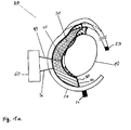
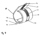
- FIG. 1a It shows a schematic cross section of a blood pressure measuring device 20. It comprises a flexible element 30 with stiffening device 31 and control line 36, a pressure sensor element 40 with sensor cable 43, a latching strip 51, an eyelet 53, a tab 54 and a control device 60.
- a body part 10 is shown as an ellipse.
- the flexible element 30 is bounded by an airtight envelope 32, which is represented by a thick black border. It contains a filling material consisting of polystyrene balls and cross-linked fibers. This filling material is characterized by a hatching (from top left, bottom right) and evenly distributed in the airtight envelope 32 and serves as a stiffening means 31.
- the shape variability is exemplified by the fact that the areas that after adaptation to the body part 10 their shape have changed, dashed lines are drawn.
- a connection hose 36 is attached to the airtight sheath 32 and the flexible member 30 as a control line for the flexible member 30. He is shown as a thick line.
- the pressure sensor element 40 is attached to the flexible element. It is attached to the surface of the flexible member 30 which faces the body part 10, that is, the inside. At the pressure sensor element, a sensor cable 43 is attached. It is marked as a thick line.
- the latching strip 51 is arranged around the flexible element 30. In the cross section shown, the latching strip 51 overlaps the flexible element 30 on two sides. The cross section shows a mounting variant of the locking strip on the flexible member 30.
- the locking strip has an eyelet 52 and a tab 53. These are shown as small black squares.
- the sensor cable 43 of the pressure sensor element and the connecting hose 36 for the flexible element 36 lead to a control device 60. The control device is shown as a large rectangle.
- the flexible member 30 When the flexible member 30 is applied to the body part 10, it is put into a shape conforming to the surface of the body part by placing the inside of the body part 10 and pressing on the body part 10.
- the inside of the flexible element 30, thereby obtains a surface profile, which is in direct contact with the body part 10 at preferably each point of the surface - except for the areas covered by a pressure sensor element.
- the pressure sensor element 40 is therefore also in direct contact with the body part 10. If the flexible element 30 is in the body part-adapted form, it is stiffened. For this purpose, air is sucked out of the flexible element 30, which here has an airtight envelope 32, via the connecting tube 36 and the filling of the airtight envelope 32 is compressed in itself.
- the composite of styrofoam balls and cross-linked fibers is wedged together so that it can no longer be changed in shape.
- the shape of the flexible element is no longer changeable. This effect is reversed by re-feeding air into the airtight envelope 32 (deactivating the stiffener).
- the ends of the latching strips 51 are moved against each other via a drawstring which connects the eyelet 52 with the tab 53, so that the flexible element 30 is placed closer to the body part 10 and presses on the body part 10. But it can also be worked without drawstring by the one end of the detent strip (which with the eyelet 53, which is then not needed) is guided directly through the tab 54 and then the ends of the detent strip are moved against each other by train at this end , The pressure on the body part 10 is regulated by tightening or loosening the locking strip.
- the pressure sensor element 40 is also pressed against the body part 10 by the flexible element 30 which is pressed against the body part 10 and a direct coupling of the pressure sensor element 40 to the body part 10 results. Therefore, pulsatile signals of the blood vessels located in the body part can be measured. The pressure sensor element 40 converts these signals into electrical signals. The electrical signals are then forwarded via the sensor cable 43.
- the control unit 60 controls the stiffening of the flexible element 30 and detects the measured values of the pressure sensor element 40.
- characteristic numbers are calculated on the basis of the available sensor values, such as HLI parameters, in particular HZV, SVV, PPV, PEPV.
- HLI parameters such as HZV, SVV, PPV, PEPV.
- the illustrated device allows pulsatile signals to be measured with a prior art increased signal-to-noise ratio. On the basis of these higher-quality signals, meaningful figures can be calculated.
- the higher signal-to-noise ratio is made possible by the optimized hydraulic coupling of one or more pressure sensor elements 40 to a body part 10.
- the hydraulic coupling is based on the possibility of being able to stiffen a flexible element 30 by a stiffening device 31.
- This flexible element is first adapted to the body part 10 and then stiffened.
- the adaptation to the body part 10 is assisted 51 by the pressure of the detent strip, so that the pressure sensor element 40 is pressed against the body part.
- pulsatile signals are no longer attenuated by absorption in flexible elements and are thus available to the pressure measurement substantially unattenuated.
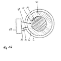
- FIG. 1b shows a schematic cross section of a blood pressure measuring device in an annular design and with a blood pressure cuff as an outer fixation.
- the body part 10 is shown hatched (from bottom left to top right). This is, for example, the human upper arm.
- the flexible member 30 has an annular shape and has an airtight shell. This is with Styrofoam balls and cross-linked fibers filled evenly. This stiffenable filling is abstracted as hatching (from top left to bottom right) and represents the stiffening device 31 of the flexible element 30.
- a pressure sensor element 40 is attached to the side of the flexible element facing the body part 10. In this schematic cross-section, the attachment of the pressure sensor element 40 to the flexible element is shown, through which the pressure sensor element is flush with one of the surfaces of the flexible element.
- a blood pressure cuff as an outer fixation 50 is shown here in an annular design.
- the diameter is larger than that of the flexible member 30, because it is attached to the outside. It has a connection hose 52 as a control line, through which air or a fluid is filled into the cuff and discharged from the cuff.
- the remaining subscribed components correspond to those from Fig. 1a ,
- the attachment of the flexible element 31 and the blood pressure cuff is carried out by slipping over the body part 10.
- the degree of external fixation ie the pressure exerted by the blood pressure cuff 50 on the body part 10, can be adjusted. Gas or liquid is introduced into the elastic element (pressure on the body part is increased) or released from the elastic element (pressure on the body part is reduced).
- the advantage of the annular embodiment is faster application of the sphygmomanometer to the body part.
- one is limited to body parts that allow slipping over the flexible element 30 here.
- the diameter of the hollow cylinder formed by the flexible element must be roughly matched to the body part.
- the use of the blood pressure cuff allows the pressure on the body part to be varied so that blood pressure can be easily measured.
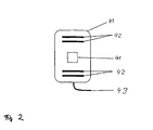
- FIG. 2 is a plan view of a pressure sensor element, which is designed as a gel pad.
- the gel pad 44 is shown as a rounded square.
- the gel pad is filled with a fluid.
- the supervision is based on the special case of a transparent gel pad filled with transparent fluid. Thus, elements within the gel pad are visible in the top view.
- the embedded in the gel pad 44 pressure sensor 41 is drawn as a rectangle in the middle of the gel pad.
- the pressure sensor is located in the center of the gel pad.
- other sensors 42 are shown. They are abstracted as dark bars.
- the other sensors are electrodes for impedance measurement.
- at least one electrode is provided as the excitation electrode and at least one electrode as the detection electrode.
- the electrical signals generated by the pressure sensor 41 and the other sensors 42 are forwarded via the sensor cable 43.
- the gel pad 44 with the integrated sensors 41, 42 constitutes a pressure sensor element, which is preferably attached to the inside of the flexible element 30. Therefore, it is pressed upon application of the flexible member 30 to the body part 10. The contact that results thereby hydraulically couples the pressure sensor located in the gel pad 44 to the body tissue. Pressure oscillations in a blood vessel present in the body part 10 are thus transferred to the pressure sensor 41 via the fluid in the gel pad 44. Due to the larger compared to the surface of the pressure sensor 41 contact surface of the gel pad 44 to the body part 10, the amplitudes of the oscillations measured at the pressure sensor 41 are higher than when directly resting the pressure sensor 41 on the body part.
- the other sensors 42 attached to the gel pad 44 are designed for an impedance measurement.
- the skin resistance and pulsatile signals can be measured, since the skin resistance changes with the changing of the A-section of the blood vessels.
- This measurement also takes place preferably on the gel pad 44, since on the one hand the direct pressure measurement by means of the pressure sensor 41 and the impedance measurement due to the local conformity can be better correlated with each other and on the other hand the gel pad 44 ensures good contact with the body part.
- a pressure sensor element as a sensor-equipped gel pad therefore offers a variety of measurement variants with simultaneous good contact with the body part.
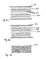
- FIG. 3a shows a schematic of a preferred embodiment of the stiffening device of the flexible element in the form of a filled with rice grains and fabric and wool fibers airtight envelope.
- a section of the airtight envelope 32 is indicated by a thick black boundary line respectively up and down.
- 32 elements of incompressible material ie substantially incompressible elements 331 are included in the filling of the airtight envelope. These are marked as circles or ellipses. These are rice grains.
- a thin dotted line represents a fabric 342 as another component of the filler. Wool fibers 341 are shown as black, curved, interlocked short lines. They too are part of the filling.
- the rice grains 331 are embedded in layers of wool fibers 341 and cloth fabric 342.
- By evacuating the in the air-tight envelope 32 compresses the compressible parts of the filling.
- the rice grains are not compressed but press against each other and wedged in the adjacent layers.
- the airtight envelope 32 is no longer depressible.
- FIG. 3b shows a schematic of a preferred embodiment of the stiffening device of the flexible element in the form of a filled with plastic granules, plastic nets and cotton fibers airtight envelope.
- the filling material now consists of substantially incompressible plastic granules 331, plastic nets 343 and cotton fibers 341.
- the layering of the fillers is done in a different order.
- plastic granules are a cost effective way of filling.
- size of the plastic granules can be adjusted to the dimensions of the body part to be adapted.
- Figure 3c shows a schematic of a preferred embodiment of the stiffening device of the flexible element in the form of a paper stack.
- the figure shows a stack of paper from several superimposed leaves 311.
- this stack When not bent, this stack is flexible. However, if it is placed inside a conventional blood pressure cuff and wrapped around, for example, the upper arm with the blood pressure cuff, the stack of paper has a stiffening effect. He can not be impressed by the pulse fluctuations of the arm. In practice, it is a blood pressure cuff provided with several layers of paper on the inside. A pressure element located between the arm and the stack of paper can thus measure signals of excellent signal quality. The paper stack can also be protected in a shell.
- the airtight envelope may be filled with multiple layers of paper or a similar material. Due to the fact that the layers of paper lie on each other with almost no gap, the cover is already very resistant to pressure even without an evacuation and offers good properties for a blood pressure measurement. If the air-tight envelope is additionally evacuated, the layers of paper form a firm bond whose rigidity continues to increase.
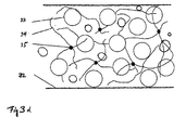
- 3d figure shows a schematic of a preferred embodiment of the stiffening means of the flexible element in the form of a styrofoam balls and fibers filled hermetic shell.
- a section of the airtight envelope 32 is indicated by a thick black boundary line respectively up and down.
- the styrofoam balls 33 are shown as circles bordered in black. They have different radii.
- the fibers 34 are drawn as partially ruffled lines.
- the arrangement of the fibers is a random networking.
- Adhesive droplets 35 are attached at some crosslinking points. These are marked as black circles.
- the mixture of components 33-35 is in the airtight envelope.
- the styrofoam balls 33 are evenly distributed in the flow-like crosslinking of the fibers 34 with the adhesive droplets 35. Air is between the individual elements of the mixture.
- the airtight sheath 32 is made of a material that is preferably flexible and impermeable to air. If there is air in the airtight envelope 32 and between the styrofoam balls 33, the airtight envelope 32 together with the mixture can be deformed.
- the airtight envelope 32 contracts and compresses the mixture in it.
- the styrofoam balls 33 and the fibers 34 lie close together and become wedged. Due to the high static friction between the individual elements caused by the mutual pressure, the mixture can no longer deform and becomes stiff. Therefore, the airtight sheath 32 also becomes stiff.
- the flexible member 30 is also stiffened because the airtight sheath 32 is the stiffener integrated into the flexible member 30.
- the airtight sheath 32 filled here with styrofoam balls 33 and preferably cross-linked by adhesive droplets 35 constitutes a stiffening device. It can be activated, for example, via a connection hose (evacuate the air in the airtight sheath) and also deactivate again (admission of air in the airtight shell). It is suitable for stiffening the flexible element 30 and returning it to a flexible state.
- FIG. 4 shows a three-dimensional drawing of a BEFORE th embodiment of the blood pressure measuring device according to the invention with blood pressure cuff, gel pad and locking strip.
- a gel pad 44 is attached to the flexible member 30 as a pressure sensor element.
- a sensor cable 43 and a control line for the flexible element 36 are led out of the device.
- a blood pressure cuff is attached as an outer fixation 50 about the flexible member 30, which allows fixation of the flexible member 30 to a body part.
- An inner or outer latching strip 51, with an eyelet 52 and a tab 53 are also attached to the flexible member 30 and to the outer fixation.
- the body part 10 When put on, the body part 10 is wrapped with the composite of flexible member 30, gel pad 44, blood pressure cuff 50, and detent tire 51 so that the flexible member 30 conforms to the body part 10, and it is fixed by the cuff 50 and / or the detent tabs 51.
- the pressure which the outer fixation 50 and / or the detent strips 51 exert on the body part is specifically varied, so that a wide variety of measurements of pulsatile signals can be carried out.
- the body part By stiffening the flexible member 30, the body part receives a rigid sheathing and the pressure sensor element 40 is rigidly coupled to the body part. This coupling is hydraulically very advantageous because energy of the pulsatile signals is not transmitted to the flexible element 30 in the stiffened state and thus is not lost for the measurement.
- FIG. 5 shows a schematic flow diagram described procedure.
- the diagram consists of labeled blocks and arrows.
- the blocks denote process steps.
- the temporal dependence of process steps relative to each other is, if relevant, indicated by arrows. It is a procedural step which is carried out according to another method step, connected by an arrow pointing to the later method step.
- Process steps without arrow connections have no compelling temporal dependence on other process steps.
- the drawn abscissa can accordingly be regarded as a time axis.
- Blocks having at least one common, vertical cutting axis can be executed in parallel in the overlapping region. If blocks are arranged exactly one below the other, the corresponding method steps can be carried out simultaneously or in any desired sequence relative to one another.
- the blocks are arranged so that a procedure is run from left to right.
- the method begins with the application of the flexible element 30 to the body part 10 intended for the measurement.
- the flexible element 30 is applied in such a way that it adapts to the body part 10. This is possible due to the deformability of the flexible element 30 that it has, as long as the stiffening device 31 of the flexible Elements 30 is not activated.
- the pressure sensor elements 40 attached to the side of the flexible element 30 facing the body part 10 are also adapted to the body part 10. This step is indicated by the block "Create 30".
- the second step of the method is then the activation of the stiffening device 31 or the stiffening of the flexible element 30.
- the flexible element 30 is then no longer deformable. It can not absorb or pass any pressure fluctuations. This step is indicated by the block "Activation of 31".
- the third step of the procedure is then to measure the pulsatile signals over a period of time.
- the pressure sensor elements 40 attached to the flexible element 30 are hydraulically optimally connected to the body part 10 because the flexible element 30 forms a rigid outer shell around the attached pressure sensor element 40 so that pressure fluctuations emanating from the body part 10 do not propagate into further components of the blood pressure measurement device and thus lose no energy that could then no longer be included in the measured by the respective pressure sensor element 40 signal.
- the measurement period includes e.g. three respiratory cycles.
- the pressure fluctuations are converted into electrical signals by the pressure sensor elements 40 attached to the flexible element 30.
- This process step is characterized by the block "measurement of pulsatile signals".
- the stiffening device 31 of the flexible element 30 is deactivated again.
- a filled with styrofoam balls 33 and crosslinked fibers 34 airtight envelope 32 the deactivation by venting the Airtight envelope 32.
- This process step is characterized by the block "Deactivation of 31".
- the method block "applying 50" indicates that a preferred further method additionally includes the step of applying an outer fixation 50 about the flexible member 30. This is preferably done after applying the flexible element 30 to the body part 10, as shown in the diagram.
- the degree of fixation of the outer fixation is also set in a targeted manner.
- the degree of fixation is adjusted so that the outer fixation 50 exerts a pressure on the body part 10 via the flexible element 30, which pressure is in the pulsatile range, ie between the systolic and the diastolic blood pressure.
- the flexible element in the pulsatile region is preferably stiffened by the subsequent method step.
- the process block "loosening of 50" indicates that when using an outer fixation 50, the outer fixation 50 is loosened again after the measurement. This prevents damage to the body part 10.
- the method block "measurement sys., Dias., Mean blood pressure” indicates that in a further preferred method systolic and / or diastolic and / or mean blood pressure is measured. This measurement takes place when the flexible element 30 is not yet in the stiffened state, as indicated in the diagram.
- the pressure acting on the body part 10 can be selectively varied, so that an oscillatory measurement of said pressures can take place.
- control / regulation indicates that in further preferred methods from the time at which the flexible element 30 is applied, a control and / or regulation of the stiffening device 31 and / or the Fix michsgrads the outer fixation 51 takes place at each subsequent time or only temporarily.
- the wide process block "impedance measurement” indicates that in another preferred method from the time the flexible element 30 is applied, measurement of the tissue resistance is provided.
- the measurement of the impedance is preferably carried out at one or more times, particularly preferably alternately for measuring the pulsatile signals by a pressure sensor element.
- blood flow is performed over an impedance measurement over three minutes. In this case, essentially no pressure is exerted on the body part by the blood pressure measuring device. The blood can flow essentially unhindered. Then pulsatile signals are measured over one minute via the pressure sensor. In this case, an interesting for the measurement pressure range is set by the outer fixation. The blood flow is interpolated. Subsequently, again, a measurement of the blood flow takes place via the impedance measurement, wherein the blood pressure measuring device in turn exerts essentially no pressure on the body part.
- the broad process block "analysis” indicates that in another preferred method from the time the flexible element 30 is applied, an analysis of the measured data is provided.
- the analysis is particularly preferably carried out at one or more points in time.
- stroke volume variation SVV
- PPV stroke volume
- HR heart rate
- HRV cardiac output
- dP / dtmax and other parameters can be calculated from the pressure measurement and pulse contour.
- the wide block "display / store” indicates that, in another preferred method, available signals and / or parameters are displayed and / or stored. This is continuous from the time of their availability possible, but preferably takes place only at a certain time, particularly preferably at several times.
- the procedures may also be repeated in parts. Thus, it is possible to continue after the disengagement of the stiffening device 31 and - if an outer fixation 50 is used - preferably after the loosening of the outer fixation 50 with the stiffening of the flexible element 30 or with the oscillatory blood pressure measurement.
- the dashed backward arrows indicate the preferred drainage paths.
- FIG. 6 shows the time course of selected state variables during an exemplary application of the blood pressure measuring device.
- the x-axis is the time t.
- the uppermost shows the course of the air pressure P Flex in the flexible element 30 relative to the atmospheric pressure P Atmo .
- the second diagram from above shows the pressure P Fix of the outer fixation 50 on the flexible element 30 and thus the body part 10 relative to the values of the systolic and diastolic blood pressures P Dias and P Sys, respectively.
- the third axis system from the top shows the course of
- the lowermost diagram shows the profile of a control signal S Flex for activating the stiffening device 31. A pump is controlled via this signal, for example.
- the value 0 means "off", the value 1 means "on”.
- the systolic, diastolic and mean blood pressures are determined.
- P Fix is increased.
- pulsatile signals are measured by the pressure sensor element, so that
- P Fix exceeds the value of systolic blood pressure and
- the systolic, diastolic and mean blood pressure can be determined. Thereafter, P Fix is increased from time t 7 to time t 8 , so that from t 8, the pressure P Fix is set to a value close to the mean blood pressure.
- the control signal S Flex is increased from 0 to 1, ie the flexible element 30 is stiffened. The transition to the stiffened state lasts from t 9 to t 10 . During this time, air is evacuated from the flexible element. The pressure in the flexible element P Flex drops below the ambient pressure P Atmo .
- the hydraulic coupling of the pressure sensing element 40 to the body part 10 is improved so that the signal quality increases - and thus also
- P Flex has reached a predetermined low value and the pump is turned off, ie S Flex is set from 1 to 0, and the flexible element is sealed by a valve.
- the pulsatile signals are then measured with very good signal quality.
- FIG. 7 shows the time course of the pressure curve measured by a pressure sensor during execution of the blood pressure measuring device with an outer fixation, which does not completely overlap the flexible element at all ends.
- the flexible element in this embodiment consists of an evacuable, airtight envelope filled with a paper stack of 40 sheets of 80 g / m 2 paper.
- This flexible element lies in a conventional blood pressure cuff and is wrapped around the upper arm.
- the blood pressure cuff does not overlap the flexible member in the longitudinal direction of the arm, but the flexible member protrudes from the blood pressure cuff.
- a YoYo pressure sensor (TM UP-Med) is located as a pressure sensor element between the flexible element and the skin.
- the lower graph describes the pressure curve with a ventilated airtight envelope measured with a high-fidelity electronic pressure sensor (in this case a yo-yo pressure sensor, TM from UP-Med) and the upper graph shows the pressure profile with the airtight envelope evacuated.
- a high-fidelity electronic pressure sensor in this case a yo-yo pressure sensor, TM from UP-Med
- the upper graph shows the pressure profile with the airtight envelope evacuated.
- FIG. 8 shows the time course of the pressure curve measured by a pressure sensor in execution of the blood pressure measuring device with an outer fixation, which completely overlaps the flexible element at all ends.
- the measured pressure signals for the case of an evacuated envelope (top) and a ventilated envelope (bottom) can be seen in two graphs. It is striking that with this embodiment, very high-quality signals are measured. The difference between the evacuated airtight shell and the ventilated is no longer very large. However, the secondary peaks in the upper graph (evacuated envelope) can be seen more clearly. The already very high signal quality with non-evacuated envelope communicates with the already in the non-evacuated state very pressure-resistant stack of paper in combination.
Landscapes
- Health & Medical Sciences (AREA)
- Life Sciences & Earth Sciences (AREA)
- Cardiology (AREA)
- Heart & Thoracic Surgery (AREA)
- Molecular Biology (AREA)
- Physiology (AREA)
- Biophysics (AREA)
- Pathology (AREA)
- Engineering & Computer Science (AREA)
- Biomedical Technology (AREA)
- Veterinary Medicine (AREA)
- Medical Informatics (AREA)
- Physics & Mathematics (AREA)
- Surgery (AREA)
- Animal Behavior & Ethology (AREA)
- General Health & Medical Sciences (AREA)
- Public Health (AREA)
- Vascular Medicine (AREA)
- Pulmonology (AREA)
- Dentistry (AREA)
- Ophthalmology & Optometry (AREA)
- Measuring Pulse, Heart Rate, Blood Pressure Or Blood Flow (AREA)
- Measuring And Recording Apparatus For Diagnosis (AREA)
Priority Applications (2)
| Application Number | Priority Date | Filing Date | Title |
|---|---|---|---|
| EP12006755.8A EP2572633A3 (de) | 2009-08-28 | 2010-08-20 | Blutdruckmessvorrichtung und Verfahren zur Blutdruckmessung eines Lebewesens |
| PL10749607T PL2348972T3 (pl) | 2009-08-28 | 2010-08-20 | Urządzenie do pomiaru ciśnienia krwi i sposób pomiaru ciśnienia krwi żywej istoty |
Applications Claiming Priority (2)
| Application Number | Priority Date | Filing Date | Title |
|---|---|---|---|
| DE102009039257A DE102009039257A1 (de) | 2009-08-28 | 2009-08-28 | Blutdruckmessvorrichtung und Verfahren zur Blutdruckmessung eines Lebewesens |
| PCT/EP2010/005138 WO2011023343A2 (de) | 2009-08-28 | 2010-08-20 | Blutdruckmessvorrichtung und verfahren zur blutdruckmessung eines lebewesens |
Related Child Applications (1)
| Application Number | Title | Priority Date | Filing Date |
|---|---|---|---|
| EP12006755.8 Division-Into | 2012-09-27 |
Publications (2)
| Publication Number | Publication Date |
|---|---|
| EP2348972A2 EP2348972A2 (de) | 2011-08-03 |
| EP2348972B1 true EP2348972B1 (de) | 2012-11-28 |
Family
ID=43217042
Family Applications (2)
| Application Number | Title | Priority Date | Filing Date |
|---|---|---|---|
| EP10749607A Active EP2348972B1 (de) | 2009-08-28 | 2010-08-20 | Blutdruckmessvorrichtung und verfahren zur blutdruckmessung eines lebewesens |
| EP12006755.8A Ceased EP2572633A3 (de) | 2009-08-28 | 2010-08-20 | Blutdruckmessvorrichtung und Verfahren zur Blutdruckmessung eines Lebewesens |
Family Applications After (1)
| Application Number | Title | Priority Date | Filing Date |
|---|---|---|---|
| EP12006755.8A Ceased EP2572633A3 (de) | 2009-08-28 | 2010-08-20 | Blutdruckmessvorrichtung und Verfahren zur Blutdruckmessung eines Lebewesens |
Country Status (8)
| Country | Link |
|---|---|
| EP (2) | EP2348972B1 (cg-RX-API-DMAC7.html) |
| JP (1) | JP2013502940A (cg-RX-API-DMAC7.html) |
| CN (1) | CN102481105A (cg-RX-API-DMAC7.html) |
| DE (1) | DE102009039257A1 (cg-RX-API-DMAC7.html) |
| ES (1) | ES2400443T3 (cg-RX-API-DMAC7.html) |
| IN (1) | IN2012DN01740A (cg-RX-API-DMAC7.html) |
| PL (1) | PL2348972T3 (cg-RX-API-DMAC7.html) |
| WO (1) | WO2011023343A2 (cg-RX-API-DMAC7.html) |
Cited By (1)
| Publication number | Priority date | Publication date | Assignee | Title |
|---|---|---|---|---|
| WO2025210637A1 (en) * | 2024-04-04 | 2025-10-09 | CardiacSense Ltd. | Wrist sensor for measuring physiological parameter |
Families Citing this family (21)
| Publication number | Priority date | Publication date | Assignee | Title |
|---|---|---|---|---|
| WO2013113333A1 (de) | 2012-02-03 | 2013-08-08 | Up-Med Gmbh | Versteifungsvorrichtung für eine blutdruckmessvorrichtung |
| WO2013113334A1 (de) | 2012-02-03 | 2013-08-08 | Up-Med Gmbh | Blutdruckmessvorrichtung, flexible manschette für eine blutdruckmessvorrichtung und verfahren zur blutdruckmessung |
| EP2953528B1 (en) | 2013-02-08 | 2018-09-19 | UP-MED GmbH | Blood pressure measuring system comprising a kinking-proof shell |
| WO2014121805A1 (en) * | 2013-02-08 | 2014-08-14 | Up-Med Gmbh | Blood pressure measuring system comprising a kinking-proof shell |
| WO2014125355A1 (en) * | 2013-02-13 | 2014-08-21 | Leman Micro Devices Sa | Non-invasive blood analysis |
| DE102013014982A1 (de) * | 2013-09-05 | 2015-03-05 | Seca Ag | Vorrichtung zur Messung von physiologischen Werten |
| CN104173036A (zh) * | 2014-09-11 | 2014-12-03 | 重庆大学 | 一种脉搏波采集装置、无创血压连续逐拍测量系统及方法 |
| JP6637701B2 (ja) * | 2015-09-04 | 2020-01-29 | 藤倉コンポジット株式会社 | 圧力計、圧力計測装置、及び血圧計 |
| US20180279889A1 (en) * | 2015-10-08 | 2018-10-04 | Charmcare Co., Ltd. | Wrist-worn blood pressure monitor |
| EP3369372B1 (en) * | 2015-11-30 | 2024-01-10 | Omron Healthcare Co., Ltd. | Soft gripper and blood pressure measuring cuff comprising same |
| CN105748056B (zh) * | 2016-04-01 | 2018-11-27 | 广州视源电子科技股份有限公司 | 血压检测系统 |
| US10722125B2 (en) * | 2016-10-31 | 2020-07-28 | Livemetric (Medical) S.A. | Blood pressure signal acquisition using a pressure sensor array |
| DE102017000940A1 (de) | 2017-02-02 | 2018-08-02 | Xenios Ag | Anordnung mit einer Blutpumpe, einer Steuereinheit und einem Gerät zur Übermittlung der Messwerte |
| JP6859154B2 (ja) * | 2017-03-29 | 2021-04-14 | 日本光電工業株式会社 | 血圧測定装置 |
| JP7150623B2 (ja) * | 2019-01-15 | 2022-10-11 | 信越ポリマー株式会社 | 家畜用センサモジュール取付具 |
| CN110301905A (zh) * | 2019-07-31 | 2019-10-08 | 安徽华米信息科技有限公司 | 生命体征检测装置及方法 |
| CN114615929A (zh) * | 2019-12-16 | 2022-06-10 | 爱德华兹生命科学公司 | 连续无创血压测量装置 |
| US12507901B2 (en) | 2020-07-14 | 2025-12-30 | Apple Inc. | Integrated flexible sensor for blood pressure measurements |
| US11744476B2 (en) | 2020-08-20 | 2023-09-05 | Apple Inc. | Blood pressure measurement using device with piezoelectric sensor |
| US12251204B2 (en) | 2021-02-03 | 2025-03-18 | Apple Inc. | Blood pressure monitoring system including a liquid filled sensor |
| WO2022249459A1 (ja) * | 2021-05-28 | 2022-12-01 | オムロンヘルスケア株式会社 | 生体情報測定装置 |
Family Cites Families (15)
| Publication number | Priority date | Publication date | Assignee | Title |
|---|---|---|---|---|
| AT381364B (de) | 1984-10-24 | 1986-10-10 | Voest Alpine Ag | Einrichtung zur zufuehrung von wasser unter druck zu austrittsduesen am umfang eines schraemwerkzeuges |
| JPH0624525B2 (ja) | 1991-07-04 | 1994-04-06 | 日本光電工業株式会社 | 連続型非観血血圧測定装置 |
| JPH08150127A (ja) * | 1994-11-29 | 1996-06-11 | Omron Corp | 血圧計用カフ |
| JPH10201723A (ja) * | 1997-01-20 | 1998-08-04 | Nippon Colin Co Ltd | 血圧測定用圧迫装置 |
| IL124787A0 (en) * | 1998-06-07 | 1999-01-26 | Itamar Medical C M 1997 Ltd | Pressure applicator devices particularly useful for non-invasive detection of medical conditions |
| US6224558B1 (en) * | 1999-03-12 | 2001-05-01 | Critikon Company, L.L.C. | Signal enhancing and artifact reducing blood pressure cuff |
| JP2001187029A (ja) * | 1999-12-28 | 2001-07-10 | Nippon Seimitsu Sokki Kk | 体脂肪率測定機能を備えた血圧計 |
| US6338719B1 (en) * | 2000-06-12 | 2002-01-15 | Rutgers, The State University Of New Jersey | Method and system for detecting vascular conditions using an occlusive arm cuff plethysmograph |
| US7011631B2 (en) * | 2003-01-21 | 2006-03-14 | Hemonix, Inc. | Noninvasive method of measuring blood density and hematocrit |
| US7422562B2 (en) | 2003-12-05 | 2008-09-09 | Edwards Lifesciences | Real-time measurement of ventricular stroke volume variations by continuous arterial pulse contour analysis |
| JP2006255097A (ja) * | 2005-03-16 | 2006-09-28 | Omron Healthcare Co Ltd | 血圧計用カフおよび血圧計 |
| DE102006004415A1 (de) | 2006-01-31 | 2007-08-09 | Up Management Gmbh & Co Med-Systems Kg | Vorrichtung zum Bewerten eines hämodynamischen Zustandes eines Patienten, wobei eine Herz-Lungen-Interaktion verwendet wird |
| JP4237193B2 (ja) * | 2006-03-29 | 2009-03-11 | シチズンホールディングス株式会社 | 血圧計用腕帯 |
| MX2009010337A (es) * | 2007-03-28 | 2009-10-19 | Kaz Inc | Monitor de presion sanguinea arterial con un brazalete lleno con liquido. |
| DE102008008840A1 (de) * | 2008-02-13 | 2009-09-24 | Up Management Gmbh | Verfahren und Vorrichtung zur nicht-invasiven Messung von dynamischen Herz-Lungen Interaktionsparametern |
-
2009
- 2009-08-28 DE DE102009039257A patent/DE102009039257A1/de not_active Ceased
-
2010
- 2010-08-20 WO PCT/EP2010/005138 patent/WO2011023343A2/de not_active Ceased
- 2010-08-20 CN CN2010800381997A patent/CN102481105A/zh active Pending
- 2010-08-20 ES ES10749607T patent/ES2400443T3/es active Active
- 2010-08-20 EP EP10749607A patent/EP2348972B1/de active Active
- 2010-08-20 PL PL10749607T patent/PL2348972T3/pl unknown
- 2010-08-20 IN IN1740DEN2012 patent/IN2012DN01740A/en unknown
- 2010-08-20 EP EP12006755.8A patent/EP2572633A3/de not_active Ceased
- 2010-08-20 JP JP2012525916A patent/JP2013502940A/ja active Pending
Cited By (1)
| Publication number | Priority date | Publication date | Assignee | Title |
|---|---|---|---|---|
| WO2025210637A1 (en) * | 2024-04-04 | 2025-10-09 | CardiacSense Ltd. | Wrist sensor for measuring physiological parameter |
Also Published As
| Publication number | Publication date |
|---|---|
| ES2400443T3 (es) | 2013-04-09 |
| WO2011023343A2 (de) | 2011-03-03 |
| JP2013502940A (ja) | 2013-01-31 |
| CN102481105A (zh) | 2012-05-30 |
| PL2348972T3 (pl) | 2013-04-30 |
| DE102009039257A1 (de) | 2011-03-10 |
| EP2572633A3 (de) | 2013-07-17 |
| EP2572633A2 (de) | 2013-03-27 |
| WO2011023343A3 (de) | 2011-04-28 |
| EP2348972A2 (de) | 2011-08-03 |
| IN2012DN01740A (cg-RX-API-DMAC7.html) | 2015-06-05 |
Similar Documents
| Publication | Publication Date | Title |
|---|---|---|
| EP2572633A2 (de) | Blutdruckmessvorrichtung und Verfahren zur Blutdruckmessung eines Lebewesens | |
| US8998817B2 (en) | Blood pressure measuring device and method for measuring the blood pressure of a living being | |
| DE102017110770B3 (de) | Verfahren zum nicht-invasiven Bestimmen von wenigstens einem Blutdruckwert, Messvorrichtung und System zur nicht-invasiven Blutdruckbestimmung | |
| DE112011100685B4 (de) | Blutdruckinformation-Messeinrichtung | |
| DE69114369T2 (de) | Gerät zur Kompression des Oberschenkels. | |
| EP2240072B1 (de) | Druckmesser, insbesondere blutdruckmesser, verfahren zur bestimmung von druckwerten, verfahren zum kalibrieren eines druckmessung und computerprogramm zur implementierung dieser verfahren | |
| EP0467853B1 (de) | Einrichtung und Verfahren zur Blutdruckmessung | |
| DE69821775T2 (de) | System und verfahren zur korrektur des gemessenen blutdrucks eines lebewesens | |
| EP2699308B1 (de) | Bandage und elektrodensystem | |
| DE3787725T2 (de) | Blutdruckregelungssystem. | |
| DE102007039936A1 (de) | Verfahren und System, die ein SpO2-Plethysmographsignal benutzen, um die Zeit zur nicht-invasiven Blutdruck(NIBP)-Bestimmung zu verringern | |
| DE102008008840A1 (de) | Verfahren und Vorrichtung zur nicht-invasiven Messung von dynamischen Herz-Lungen Interaktionsparametern | |
| EP3125743B1 (de) | Verfahren zur bestimmung des blutdrucks in einem blutgefäss sowie vorrichtung zur durchführung desselben | |
| WO2019106535A1 (de) | Druckmessvorrichtung zur druckmessung und/oder elastizitätsmessung einer vene oder eines organs und zur kombination mit einer ultraschallmesseinheit, druckmesssystem und verfahren | |
| EP2323545A2 (de) | Piezoelektrischer sensor zur druckfluktuationsmessung | |
| DE102007042298A1 (de) | Verfahren und System zum qualitativen Einschätzen von NIBP-Pulsen unter Verwendung eines SpO2-Lethysmographischen Signals | |
| WO2013113334A1 (de) | Blutdruckmessvorrichtung, flexible manschette für eine blutdruckmessvorrichtung und verfahren zur blutdruckmessung | |
| DE112011104312B4 (de) | Blutdruckinformation-Messeinrichtung und Verfahren für das Berechnen des Indexes des Grades der Arteriosklerose mit dieser Einrichtung | |
| DE69216066T2 (de) | Hämostatischer Druckgürtel | |
| DE102004009879A1 (de) | Verfahren und System zum Modifizieren des Manschettendrucks | |
| DE60033592T2 (de) | Blutdruckmessmanschette, welche das Signal verbessert und die parasitären Signale vermindert | |
| DE102009026012A1 (de) | Blutdruckmanschettenvorrichtung und -system | |
| DE60031681T2 (de) | Verfahren und Vorrichtung zum Messen des Blutdrucks | |
| DE102017002334A1 (de) | Zeitaufgelöste Messung von Kenngrößen der Herzfunktion durch autonom verstellbare Meßbereiche, wie z.B. Herzzeitvolumen, Blutdruck, Herzpuls, Pulswellenlaufzeit, Pulswellenvariabilität, Atmungsfrequenz ... | |
| EP3151740B1 (de) | Vorrichtung zur nicht invasiven messung des blutflusses |
Legal Events
| Date | Code | Title | Description |
|---|---|---|---|
| PUAI | Public reference made under article 153(3) epc to a published international application that has entered the european phase |
Free format text: ORIGINAL CODE: 0009012 |
|
| AK | Designated contracting states |
Kind code of ref document: A2 Designated state(s): AL AT BE BG CH CY CZ DE DK EE ES FI FR GB GR HR HU IE IS IT LI LT LU LV MC MK MT NL NO PL PT RO SE SI SK SM TR |
|
| 17P | Request for examination filed |
Effective date: 20110401 |
|
| GRAP | Despatch of communication of intention to grant a patent |
Free format text: ORIGINAL CODE: EPIDOSNIGR1 |
|
| DAX | Request for extension of the european patent (deleted) | ||
| GRAS | Grant fee paid |
Free format text: ORIGINAL CODE: EPIDOSNIGR3 |
|
| GRAA | (expected) grant |
Free format text: ORIGINAL CODE: 0009210 |
|
| AK | Designated contracting states |
Kind code of ref document: B1 Designated state(s): AL AT BE BG CH CY CZ DE DK EE ES FI FR GB GR HR HU IE IS IT LI LT LU LV MC MK MT NL NO PL PT RO SE SI SK SM TR |
|
| REG | Reference to a national code |
Ref country code: GB Ref legal event code: FG4D Free format text: NOT ENGLISH |
|
| REG | Reference to a national code |
Ref country code: CH Ref legal event code: EP |
|
| REG | Reference to a national code |
Ref country code: AT Ref legal event code: REF Ref document number: 585729 Country of ref document: AT Kind code of ref document: T Effective date: 20121215 |
|
| REG | Reference to a national code |
Ref country code: IE Ref legal event code: FG4D Free format text: LANGUAGE OF EP DOCUMENT: GERMAN |
|
| REG | Reference to a national code |
Ref country code: CH Ref legal event code: NV Representative=s name: RIEDERER HASLER AND PARTNER PATENTANWAELTE AG, LI |
|
| REG | Reference to a national code |
Ref country code: DE Ref legal event code: R096 Ref document number: 502010001771 Country of ref document: DE Effective date: 20130124 |
|
| REG | Reference to a national code |
Ref country code: SE Ref legal event code: TRGR |
|
| REG | Reference to a national code |
Ref country code: NL Ref legal event code: T3 |
|
| REG | Reference to a national code |
Ref country code: ES Ref legal event code: FG2A Ref document number: 2400443 Country of ref document: ES Kind code of ref document: T3 Effective date: 20130409 |
|
| REG | Reference to a national code |
Ref country code: LT Ref legal event code: MG4D |
|
| PG25 | Lapsed in a contracting state [announced via postgrant information from national office to epo] |
Ref country code: LT Free format text: LAPSE BECAUSE OF FAILURE TO SUBMIT A TRANSLATION OF THE DESCRIPTION OR TO PAY THE FEE WITHIN THE PRESCRIBED TIME-LIMIT Effective date: 20121128 Ref country code: FI Free format text: LAPSE BECAUSE OF FAILURE TO SUBMIT A TRANSLATION OF THE DESCRIPTION OR TO PAY THE FEE WITHIN THE PRESCRIBED TIME-LIMIT Effective date: 20121128 Ref country code: NO Free format text: LAPSE BECAUSE OF FAILURE TO SUBMIT A TRANSLATION OF THE DESCRIPTION OR TO PAY THE FEE WITHIN THE PRESCRIBED TIME-LIMIT Effective date: 20130228 |
|
| REG | Reference to a national code |
Ref country code: PL Ref legal event code: T3 |
|
| PG25 | Lapsed in a contracting state [announced via postgrant information from national office to epo] |
Ref country code: PT Free format text: LAPSE BECAUSE OF FAILURE TO SUBMIT A TRANSLATION OF THE DESCRIPTION OR TO PAY THE FEE WITHIN THE PRESCRIBED TIME-LIMIT Effective date: 20130328 Ref country code: GR Free format text: LAPSE BECAUSE OF FAILURE TO SUBMIT A TRANSLATION OF THE DESCRIPTION OR TO PAY THE FEE WITHIN THE PRESCRIBED TIME-LIMIT Effective date: 20130301 Ref country code: SI Free format text: LAPSE BECAUSE OF FAILURE TO SUBMIT A TRANSLATION OF THE DESCRIPTION OR TO PAY THE FEE WITHIN THE PRESCRIBED TIME-LIMIT Effective date: 20121128 Ref country code: LV Free format text: LAPSE BECAUSE OF FAILURE TO SUBMIT A TRANSLATION OF THE DESCRIPTION OR TO PAY THE FEE WITHIN THE PRESCRIBED TIME-LIMIT Effective date: 20121128 |
|
| PG25 | Lapsed in a contracting state [announced via postgrant information from national office to epo] |
Ref country code: CZ Free format text: LAPSE BECAUSE OF FAILURE TO SUBMIT A TRANSLATION OF THE DESCRIPTION OR TO PAY THE FEE WITHIN THE PRESCRIBED TIME-LIMIT Effective date: 20121128 Ref country code: BG Free format text: LAPSE BECAUSE OF FAILURE TO SUBMIT A TRANSLATION OF THE DESCRIPTION OR TO PAY THE FEE WITHIN THE PRESCRIBED TIME-LIMIT Effective date: 20130228 Ref country code: EE Free format text: LAPSE BECAUSE OF FAILURE TO SUBMIT A TRANSLATION OF THE DESCRIPTION OR TO PAY THE FEE WITHIN THE PRESCRIBED TIME-LIMIT Effective date: 20121128 Ref country code: DK Free format text: LAPSE BECAUSE OF FAILURE TO SUBMIT A TRANSLATION OF THE DESCRIPTION OR TO PAY THE FEE WITHIN THE PRESCRIBED TIME-LIMIT Effective date: 20121128 Ref country code: SK Free format text: LAPSE BECAUSE OF FAILURE TO SUBMIT A TRANSLATION OF THE DESCRIPTION OR TO PAY THE FEE WITHIN THE PRESCRIBED TIME-LIMIT Effective date: 20121128 |
|
| PG25 | Lapsed in a contracting state [announced via postgrant information from national office to epo] |
Ref country code: RO Free format text: LAPSE BECAUSE OF FAILURE TO SUBMIT A TRANSLATION OF THE DESCRIPTION OR TO PAY THE FEE WITHIN THE PRESCRIBED TIME-LIMIT Effective date: 20121128 |
|
| PLBE | No opposition filed within time limit |
Free format text: ORIGINAL CODE: 0009261 |
|
| STAA | Information on the status of an ep patent application or granted ep patent |
Free format text: STATUS: NO OPPOSITION FILED WITHIN TIME LIMIT |
|
| PGFP | Annual fee paid to national office [announced via postgrant information from national office to epo] |
Ref country code: NL Payment date: 20130822 Year of fee payment: 4 Ref country code: SE Payment date: 20130822 Year of fee payment: 4 Ref country code: ES Payment date: 20130828 Year of fee payment: 4 |
|
| 26N | No opposition filed |
Effective date: 20130829 |
|
| PG25 | Lapsed in a contracting state [announced via postgrant information from national office to epo] |
Ref country code: CY Free format text: LAPSE BECAUSE OF FAILURE TO SUBMIT A TRANSLATION OF THE DESCRIPTION OR TO PAY THE FEE WITHIN THE PRESCRIBED TIME-LIMIT Effective date: 20121128 Ref country code: HR Free format text: LAPSE BECAUSE OF FAILURE TO SUBMIT A TRANSLATION OF THE DESCRIPTION OR TO PAY THE FEE WITHIN THE PRESCRIBED TIME-LIMIT Effective date: 20121128 |
|
| PGFP | Annual fee paid to national office [announced via postgrant information from national office to epo] |
Ref country code: PL Payment date: 20130808 Year of fee payment: 4 |
|
| REG | Reference to a national code |
Ref country code: DE Ref legal event code: R097 Ref document number: 502010001771 Country of ref document: DE Effective date: 20130829 |
|
| PGFP | Annual fee paid to national office [announced via postgrant information from national office to epo] |
Ref country code: IT Payment date: 20130831 Year of fee payment: 4 |
|
| BERE | Be: lapsed |
Owner name: UP-MED G.M.B.H. Effective date: 20130831 |
|
| PG25 | Lapsed in a contracting state [announced via postgrant information from national office to epo] |
Ref country code: MC Free format text: LAPSE BECAUSE OF FAILURE TO SUBMIT A TRANSLATION OF THE DESCRIPTION OR TO PAY THE FEE WITHIN THE PRESCRIBED TIME-LIMIT Effective date: 20121128 |
|
| REG | Reference to a national code |
Ref country code: IE Ref legal event code: MM4A |
|
| PG25 | Lapsed in a contracting state [announced via postgrant information from national office to epo] |
Ref country code: BE Free format text: LAPSE BECAUSE OF NON-PAYMENT OF DUE FEES Effective date: 20130831 |
|
| REG | Reference to a national code |
Ref country code: DE Ref legal event code: R082 Ref document number: 502010001771 Country of ref document: DE Representative=s name: TER MEER STEINMEISTER & PARTNER PATENTANWAELTE, DE Ref country code: DE Ref legal event code: R082 Ref document number: 502010001771 Country of ref document: DE Representative=s name: V. FUENER EBBINGHAUS FINCK HANO, DE Ref country code: DE Ref legal event code: R082 Ref document number: 502010001771 Country of ref document: DE Representative=s name: PATENTANWAELTE LAMBSDORFF & LANGE, DE |
|
| PG25 | Lapsed in a contracting state [announced via postgrant information from national office to epo] |
Ref country code: IE Free format text: LAPSE BECAUSE OF NON-PAYMENT OF DUE FEES Effective date: 20130820 |
|
| REG | Reference to a national code |
Ref country code: DE Ref legal event code: R082 Ref document number: 502010001771 Country of ref document: DE Representative=s name: TER MEER STEINMEISTER & PARTNER PATENTANWAELTE, DE Ref country code: DE Ref legal event code: R082 Ref document number: 502010001771 Country of ref document: DE Ref country code: DE Ref legal event code: R082 Ref document number: 502010001771 Country of ref document: DE Representative=s name: V. FUENER EBBINGHAUS FINCK HANO, DE |
|
| REG | Reference to a national code |
Ref country code: NL Ref legal event code: V1 Effective date: 20150301 |
|
| REG | Reference to a national code |
Ref country code: SE Ref legal event code: EUG Ref country code: CH Ref legal event code: PL |
|
| GBPC | Gb: european patent ceased through non-payment of renewal fee |
Effective date: 20140820 |
|
| PG25 | Lapsed in a contracting state [announced via postgrant information from national office to epo] |
Ref country code: CH Free format text: LAPSE BECAUSE OF NON-PAYMENT OF DUE FEES Effective date: 20140831 Ref country code: NL Free format text: LAPSE BECAUSE OF NON-PAYMENT OF DUE FEES Effective date: 20150301 Ref country code: LI Free format text: LAPSE BECAUSE OF NON-PAYMENT OF DUE FEES Effective date: 20140831 Ref country code: IT Free format text: LAPSE BECAUSE OF NON-PAYMENT OF DUE FEES Effective date: 20140820 |
|
| PG25 | Lapsed in a contracting state [announced via postgrant information from national office to epo] |
Ref country code: SM Free format text: LAPSE BECAUSE OF FAILURE TO SUBMIT A TRANSLATION OF THE DESCRIPTION OR TO PAY THE FEE WITHIN THE PRESCRIBED TIME-LIMIT Effective date: 20121128 Ref country code: SE Free format text: LAPSE BECAUSE OF NON-PAYMENT OF DUE FEES Effective date: 20140821 |
|
| PG25 | Lapsed in a contracting state [announced via postgrant information from national office to epo] |
Ref country code: TR Free format text: LAPSE BECAUSE OF FAILURE TO SUBMIT A TRANSLATION OF THE DESCRIPTION OR TO PAY THE FEE WITHIN THE PRESCRIBED TIME-LIMIT Effective date: 20121128 Ref country code: MT Free format text: LAPSE BECAUSE OF FAILURE TO SUBMIT A TRANSLATION OF THE DESCRIPTION OR TO PAY THE FEE WITHIN THE PRESCRIBED TIME-LIMIT Effective date: 20121128 |
|
| PG25 | Lapsed in a contracting state [announced via postgrant information from national office to epo] |
Ref country code: MK Free format text: LAPSE BECAUSE OF FAILURE TO SUBMIT A TRANSLATION OF THE DESCRIPTION OR TO PAY THE FEE WITHIN THE PRESCRIBED TIME-LIMIT Effective date: 20121128 Ref country code: LU Free format text: LAPSE BECAUSE OF NON-PAYMENT OF DUE FEES Effective date: 20130820 Ref country code: GB Free format text: LAPSE BECAUSE OF NON-PAYMENT OF DUE FEES Effective date: 20140820 Ref country code: HU Free format text: LAPSE BECAUSE OF FAILURE TO SUBMIT A TRANSLATION OF THE DESCRIPTION OR TO PAY THE FEE WITHIN THE PRESCRIBED TIME-LIMIT; INVALID AB INITIO Effective date: 20100820 |
|
| REG | Reference to a national code |
Ref country code: FR Ref legal event code: PLFP Year of fee payment: 6 |
|
| REG | Reference to a national code |
Ref country code: ES Ref legal event code: FD2A Effective date: 20150925 |
|
| PG25 | Lapsed in a contracting state [announced via postgrant information from national office to epo] |
Ref country code: ES Free format text: LAPSE BECAUSE OF NON-PAYMENT OF DUE FEES Effective date: 20140821 |
|
| PG25 | Lapsed in a contracting state [announced via postgrant information from national office to epo] |
Ref country code: PL Free format text: LAPSE BECAUSE OF NON-PAYMENT OF DUE FEES Effective date: 20140820 |
|
| REG | Reference to a national code |
Ref country code: PL Ref legal event code: LAPE |
|
| REG | Reference to a national code |
Ref country code: DE Ref legal event code: R082 Ref document number: 502010001771 Country of ref document: DE Ref country code: DE Ref legal event code: R082 Ref document number: 502010001771 Country of ref document: DE Representative=s name: TER MEER STEINMEISTER & PARTNER PATENTANWAELTE, DE |
|
| PG25 | Lapsed in a contracting state [announced via postgrant information from national office to epo] |
Ref country code: IS Free format text: LAPSE BECAUSE OF FAILURE TO SUBMIT A TRANSLATION OF THE DESCRIPTION OR TO PAY THE FEE WITHIN THE PRESCRIBED TIME-LIMIT Effective date: 20121128 |
|
| REG | Reference to a national code |
Ref country code: DE Ref legal event code: R082 Ref document number: 502010001771 Country of ref document: DE |
|
| REG | Reference to a national code |
Ref country code: FR Ref legal event code: PLFP Year of fee payment: 7 |
|
| REG | Reference to a national code |
Ref country code: AT Ref legal event code: MM01 Ref document number: 585729 Country of ref document: AT Kind code of ref document: T Effective date: 20150820 |
|
| PG25 | Lapsed in a contracting state [announced via postgrant information from national office to epo] |
Ref country code: AT Free format text: LAPSE BECAUSE OF NON-PAYMENT OF DUE FEES Effective date: 20150820 |
|
| REG | Reference to a national code |
Ref country code: FR Ref legal event code: PLFP Year of fee payment: 8 |
|
| REG | Reference to a national code |
Ref country code: FR Ref legal event code: PLFP Year of fee payment: 9 |
|
| PG25 | Lapsed in a contracting state [announced via postgrant information from national office to epo] |
Ref country code: AL Free format text: LAPSE BECAUSE OF FAILURE TO SUBMIT A TRANSLATION OF THE DESCRIPTION OR TO PAY THE FEE WITHIN THE PRESCRIBED TIME-LIMIT Effective date: 20121128 |
|
| REG | Reference to a national code |
Ref country code: DE Ref legal event code: R082 Ref document number: 502010001771 Country of ref document: DE Ref country code: DE Ref legal event code: R081 Ref document number: 502010001771 Country of ref document: DE Owner name: PHILIPS MEDIZIN SYSTEME BOEBLINGEN GMBH, DE Free format text: FORMER OWNER: UP-MED GMBH, 81673 MUENCHEN, DE |
|
| PGFP | Annual fee paid to national office [announced via postgrant information from national office to epo] |
Ref country code: DE Payment date: 20250827 Year of fee payment: 16 |
|
| PGFP | Annual fee paid to national office [announced via postgrant information from national office to epo] |
Ref country code: FR Payment date: 20250825 Year of fee payment: 16 |