EP2348522B1 - Bouton ou interrupteur d'installation doté d'une bascule ayant une sortie de lumière pour un éclairage - Google Patents
Bouton ou interrupteur d'installation doté d'une bascule ayant une sortie de lumière pour un éclairage Download PDFInfo
- Publication number
- EP2348522B1 EP2348522B1 EP10014722.2A EP10014722A EP2348522B1 EP 2348522 B1 EP2348522 B1 EP 2348522B1 EP 10014722 A EP10014722 A EP 10014722A EP 2348522 B1 EP2348522 B1 EP 2348522B1
- Authority
- EP
- European Patent Office
- Prior art keywords
- contact
- button
- rocker
- installation switch
- switch
- Prior art date
- Legal status (The legal status is an assumption and is not a legal conclusion. Google has not performed a legal analysis and makes no representation as to the accuracy of the status listed.)
- Not-in-force
Links
Images

Classifications
-
- H—ELECTRICITY
- H01—ELECTRIC ELEMENTS
- H01H—ELECTRIC SWITCHES; RELAYS; SELECTORS; EMERGENCY PROTECTIVE DEVICES
- H01H23/00—Tumbler or rocker switches, i.e. switches characterised by being operated by rocking an operating member in the form of a rocker button
- H01H23/02—Details
- H01H23/025—Light-emitting indicators
-
- H—ELECTRICITY
- H01—ELECTRIC ELEMENTS
- H01H—ELECTRIC SWITCHES; RELAYS; SELECTORS; EMERGENCY PROTECTIVE DEVICES
- H01H9/00—Details of switching devices, not covered by groups H01H1/00 - H01H7/00
- H01H9/16—Indicators for switching condition, e.g. "on" or "off"
- H01H9/161—Indicators for switching condition, e.g. "on" or "off" comprising light emitting elements
- H01H2009/164—Indicators for switching condition, e.g. "on" or "off" comprising light emitting elements the light emitting elements being incorporated in and movable with the operating part
Definitions
- the invention relates to an electrical installation switch or button with device base / switch insert with terminals for phase, neutral and switched outputs and a rocker with a light outlet for lighting in a side edge for installation in a standard flush-mounted box (especially according to DIN 49073 ).
- From the DE 10 2007 045 578 B3 is a formed of a top and a base part first housing existing electrical switch with a rocker switch known whose translucent areas are illuminated.
- the luminaire device having at least one luminous means is provided with a second housing to be fixed to the first housing.
- the luminaire device is provided with spring-loaded contact elements, which are on the one hand connected to the lamp in conjunction and on the other hand coming into contact with arranged in the first housing fixed contact parts contact. For this purpose, corresponding openings for the spring-loaded contact elements of the lighting device are present in the first housing.
- an electrical / electronic installation device is known that consists of a base part, a support part fixed to the base part, a cover frame and a lighting device.
- the lighting device has an at least equipped with a light emitting diode and other electronic components electrical circuit board. In operative connection with the light-emitting diode, at least one first light-conducting element is provided. At least a second light guide element is fixed to the top of the support ring. With its Lichteinkoppel Anlagen the second light guide element is directly associated with the first light guide element and with its Lichtauskoppel Scheme directly present on the cover light emission window.
- an installation switch or button with device base, rocker and lighting wherein a light guide is arranged on the back of the rocker and wherein in the device base a lamp holder is arranged with a lamp whose light radiates into a light entry surface of the light guide.
- the rocker has a light outlet opening on its installation edge mounted on the installation switch or button, preferably in the direction of the floor, which receives a light outlet surface of the light guide, so that the located below the installed installation switch or button floor is illuminated.
- the installation switch or button can also be mounted rotated by 180 °, so that the light outlet opening radiates towards the ceiling, resulting in a very bright, preferably white ceiling for the reflection of the radiated light, whereby the desired floor lighting is realized.
- From the DE 203 13 428 U1 is known from a mounting plate, a light-emitting diodes and possibly other electronic components printed circuit board with power supply lines, a light distribution panel and a frame with a light outlet opening existing light known.
- the power supply lines are led to a connection box arranged essentially behind the luminaire, in which a transformer which can be connected to the power network is arranged.
- the connection cables of several luminaires behind a wall covering can be routed to a central connection point where a low-voltage source (transformer) is installed.
- the invention has for its object to provide an optimized in terms of energy efficiency and light intensity electrical installation switch or button with device base / switch insert with a rocker with a light outlet for lighting.
- the advantages which can be achieved with the invention are, in particular, that the direct use of the LED illuminant in the rocker achieves a significantly higher light intensity compared to the known state of the art, while at the same time substantially increasing the efficiency.
- the way to the switch is illuminated so that z. B. lying on the floor objects are very well recognized, which a risk of tripping is significantly reduced.
- common device base / switch inserts can be used, which a converter is attached to the bottom side. Only the rocker is a newly to be developed, to be manufactured and to be provided component.
- the electrical contact between the LED bulb in the rocker and the converter is carried out in the device base / switch insert contacting, which disassembly of the rocker (including LED bulbs) allow from the device base / switch insert, without that would be previously to solve electrical lines.
- a retrofit of the installation switch or pushbutton from a device without lighting or a device with orientation lighting to the proposed device with lighting at a later date is always easily and inexpensively possible, it is only to replace the existing rocker against the proposed rocker with lighting, is also place the converter on the bottom side of the device base / switch insert.
- the device base / switch insert without plugged converter corresponds exactly to the device base / switch insert, as it is also used for a conventional installation switch or push button.
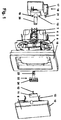
- the device base / switch insert 4 of course has a support ring 6 and spring struts 7 for mounting in the flush-mounted box.
- the rocker 9 has a light outlet 10, preferably including optical lens, at its mounted on the installation switch or switch preferably in the direction of the floor side edge, so that the floor located below the mounted installation switch or button is illuminated.
- a light outlet 10 preferably including optical lens
- serving converter 18 is plugged (mounted) on the bottom side of the device base / switch insert 4 and has a cuboid housing laterally lifted cover portion 17 which is provided in the direction of the bottom side of the device base / switch insert 4 with at least one pin 21.
- the converter 18 is provided centrally with a sleeve 20 directed towards the bottom side of the appliance base / switch insert 4. This sleeve 20 immersed in plugged converter 18 in a central bore of the device base / switching insert. 4
- two contacts 19 are arranged for the primary connection of the converter 18 in the region of the housing bottom. These two contacts 19 in the assembled state preferably contact two contacts in the bottom of the device base / switch insert 4 which are electrically connected to the two terminals 5 for the neutral conductor N and for a covered by the cover 17 second switched output.
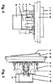
- FIG. 2 3rd are two side views of an electrical installation switch or - button shown (against each other rotated by 90 °), wherein in both representations of the electrical installation switch or button 1 each of the converter 18 is plugged (mounted) on the bottom side of the device socket / switch insert 4.
- the support ring 6 There are each of the support ring 6, the position of the terminals 5 including Klemmfederlösetasten, the spring struts 7, the cover 16 and the rocker 9 including light outlet 10 can be seen.
- the support ring 6 the position of the terminals 5 including Klemmfederlösetasten, the spring struts 7, the cover 16 and the rocker 9 including light outlet 10 can be seen.
- cover 17 which covers one of the two arranged on the bottom side of the device base / switch insert 4 switched outputs and engages with bolts 21 in the insertion openings for the lead wire, which is for the rotationally secure locking of the converter 18 on the device base / switching insert. 4 contributes.
- Fig. 4 is a view of the underside of an electrical installation switch or button shown. It can be seen that in spite of the mounted on the bottom side of the device base / switch insert 4 (mounted) converter 18 is given the free access to three of the four terminals 5, namely the terminal for the phase L, the terminal for the neutral conductor N and Terminal for a first switched output. The terminal for a second switched output is covered by the cover portion 17. Furthermore, the support ring 6 and the spring struts 7 of the device base / switch insert 4 and the over the support ring 6 cross-edge portion of the cover 16 of the electrical installation switch or button 1 are shown.
- Fig. 5 a lateral section through an electrical installation switch or push button is shown.
- an LED light-emitting means 13 is arranged.
- the LED illuminant 13 is electrically connected to the circuit board 11.
- the heat generated by the LED bulb 13 during operation heat dissipated to the outside atmosphere.
- Fig. 5 shows in particular the central bore of the device base / switching insert 4, in which both the sleeve 20 and the cylindrical portion of the contact part 22 dive. Furthermore, the support ring 6, the terminals 5 including clamping spring release buttons and the cover 16 of the installation switch or button can be seen.
- the LED illuminant 13 itself can consist of one LED or also of several LEDs, depending on which light intensity is desired.
- the installation switch or button can also be mounted rotated by 180 °, so that the light outlet 10 radiates towards the ceiling, resulting in a very bright, preferably white ceiling for reflection, whereby a desired floor lighting is realized.
- the invention can be used universally for arrangements in switch-off, changeover, cross-circuiting and key switches.
Landscapes
- Switch Cases, Indication, And Locking (AREA)
- Arrangement Of Elements, Cooling, Sealing, Or The Like Of Lighting Devices (AREA)
- Tumbler Switches (AREA)
- Push-Button Switches (AREA)
- Connector Housings Or Holding Contact Members (AREA)
- Details Of Connecting Devices For Male And Female Coupling (AREA)
Claims (8)
- Commutateur ou bouton d'installation électrique (1) comportant une douille d'appareil/un insert de commutation (4) ayant des bornes de connexion (5) destinées à la phase, au conducteur neutre et aux sorties connectées et un commutateur à bascule (9) comportant une sortie de lumière (10) destinée à un éclairage dans un bord latéral,- dans lequel un bloc d'alimentation est monté sur la face inférieure de la douille d'appareil/de l'insert de commutation (4),- dans lequel le bloc d'alimentation met respectivement en contact, côté primaire, par l'intermédiaire de contacts (19), deux bornes de connexion (5) avec des composants électriquement connectés auxdites bornes de connexion (5),caractérisé- en ce qu'un moyen d'éclairage à LED (13) est monté dans le commutateur à bascule (9) et- en ce que le bloc d'alimentation, côté secondaire, vient au contact du moyen d'éclairage à LED (13) par l'intermédiaire d'une pièce de contact (22) insérée entre le bloc d'alimentation et le commutateur à bascule, dans lequel la pièce de contact (22) comporte des éléments de mise en contact (23) qui viennent électriquement au contact de la connexion secondaire du convertisseur (18), et- la pièce de contact (22) comporte d'autres surfaces de contact (24) qui entrent électriquement en contact avec des tiges de contact élastiques (12) correspondantes d'une carte de circuit imprimé (11), dans lequel la carte de circuit imprimé (11) est montée sur la face arrière du commutateur à bascule (9).
- Commutateur ou bouton d'installation électrique (1) selon la revendication 1, caractérisé en ce que la mise en contact du moyen d'éclairage à LED (13) s'effectue par l'intermédiaire de tiges de contact élastiques (12) coopérant avec des surfaces de contact (24).
- Commutateur ou bouton d'installation électrique (1) selon la revendication 2, caractérisé en ce que les tiges de contact élastiques (12) sont réalisées sous la forme de composants d'une carte de circuit imprimé (11) qui est montée sur la face arrière du commutateur à bascule (9).
- Commutateur ou bouton d'installation électrique (1) selon la revendication 2, caractérisé en ce que les tiges de contact élastiques (12) sont réalisées sous la forme de composants d'une carte de circuit imprimé (11) qui est montée sur la face avant de la douille d'appareil/de l'insert de commutation (4).
- Commutateur ou bouton d'installation électrique (1) selon l'une quelconque des revendications précédentes, caractérisé en ce que la pièce de contact (22) comporte une section cylindrique ayant des éléments de mise en contact (23), qui s'engage en établissant un contact électrique dans un manchon (20) du bloc d'alimentation.
- Commutateur ou bouton d'installation électrique (1) selon l'une quelconque des revendications précédentes, caractérisé en ce que le bloc d'alimentation comporte une section formant capot (17) qui d'une part recouvre l'une de deux bornes de connexion (5) disposées sur la partie inférieure de la douille d'appareil/de l'insert de commutation (4) de deux sorties connectées et qui d'autre part vient électriquement au contact de ladite sortie recouverte.
- Commutateur ou bouton d'installation électrique (1) selon la revendication 6, caractérisé en ce que la section formant capot (17) comporte au moins un boulon (21) qui s'engage en se bloquant dans les bornes de connexion recouvertes (5).
- Commutateur ou bouton d'installation électrique (1) selon l'une quelconque des revendications précédentes, caractérisé en ce que le commutateur à bascule (9) comporte un corps de refroidissement (14) destiné à évacuer la chaleur dégagée par le moyen d'éclairage à LED (13).
Applications Claiming Priority (1)
| Application Number | Priority Date | Filing Date | Title |
|---|---|---|---|
| DE102010005507A DE102010005507B4 (de) | 2010-01-23 | 2010-01-23 | Installationsschalter oder -taster mit einer Wippe mit einem Lichtauslass für eine Beleuchtung |
Publications (3)
| Publication Number | Publication Date |
|---|---|
| EP2348522A2 EP2348522A2 (fr) | 2011-07-27 |
| EP2348522A3 EP2348522A3 (fr) | 2012-03-28 |
| EP2348522B1 true EP2348522B1 (fr) | 2016-08-17 |
Family
ID=43899578
Family Applications (1)
| Application Number | Title | Priority Date | Filing Date |
|---|---|---|---|
| EP10014722.2A Not-in-force EP2348522B1 (fr) | 2010-01-23 | 2010-11-18 | Bouton ou interrupteur d'installation doté d'une bascule ayant une sortie de lumière pour un éclairage |
Country Status (7)
| Country | Link |
|---|---|
| EP (1) | EP2348522B1 (fr) |
| CN (1) | CN102136379B (fr) |
| DE (1) | DE102010005507B4 (fr) |
| DK (1) | DK2348522T3 (fr) |
| ES (1) | ES2603980T3 (fr) |
| PL (1) | PL2348522T3 (fr) |
| PT (1) | PT2348522T (fr) |
Cited By (1)
| Publication number | Priority date | Publication date | Assignee | Title |
|---|---|---|---|---|
| CN106229203A (zh) * | 2016-08-31 | 2016-12-14 | 乐清市鸿基贸易有限公司 | 一种调光装置 |
Families Citing this family (7)
| Publication number | Priority date | Publication date | Assignee | Title |
|---|---|---|---|---|
| ES2614503T3 (es) * | 2012-04-20 | 2017-05-31 | Schneider Electric Industries Sas | Interruptor con medio de iluminación y módulo electrónico adaptable |
| CN104867759A (zh) * | 2015-04-27 | 2015-08-26 | 苏州贝腾特电子科技有限公司 | 用于配电柜双电源转换开关的远程电动操作机构 |
| CN106876181A (zh) * | 2015-04-27 | 2017-06-20 | 赵牧青 | 具有切换操作机构的电力开关 |
| CN104867723A (zh) * | 2015-04-27 | 2015-08-26 | 苏州君丰辰电子科技有限公司 | 智能家居电力开关 |
| CN104851699A (zh) * | 2015-04-27 | 2015-08-19 | 苏州君丰辰电子科技有限公司 | 手电动一体化切换操作机构 |
| CN104851704A (zh) * | 2015-04-27 | 2015-08-19 | 苏州君丰辰电子科技有限公司 | 用于输配电双电源开关的切换操作机构 |
| CN104867721A (zh) * | 2015-04-27 | 2015-08-26 | 苏州君丰辰电子科技有限公司 | 一种用于输配电双电源开关的切换操作机构 |
Family Cites Families (7)
| Publication number | Priority date | Publication date | Assignee | Title |
|---|---|---|---|---|
| DE20313428U1 (de) | 2003-08-29 | 2003-11-27 | Hoffmeister Leuchten Gmbh | Elektrische Leuchte |
| DE102005008755B3 (de) * | 2005-02-25 | 2006-05-24 | Siemens Ag | Elektrischer Installationsschalter in Modularbauweise mit austauschbarer Beleuchtungseinheit |
| DE102006017915B3 (de) * | 2006-04-18 | 2007-08-02 | Albrecht Jung Gmbh & Co. Kg | Elektrisches/elektronisches Installationsgerät |
| DE102007001850B3 (de) | 2007-01-12 | 2008-02-14 | Abb Patent Gmbh | Installationsschalter oder -taster mit Beleuchtung und Baukastensystem zur Bildung eines Installationsschalters oder -tasters mit Beleuchtung |
| DE102007018177B3 (de) * | 2007-04-18 | 2008-08-14 | Abb Ag | Steckdose mit Orientierungsbeleuchtung |
| DE102007045578B3 (de) * | 2007-09-24 | 2008-10-02 | Berker Gmbh & Co. Kg | Elektrischer Schalter |
| DE102008017653B4 (de) * | 2008-04-04 | 2010-02-25 | EVN Elektro-Vertrieb-Nürnberg GmbH | Leuchtvorrichtung |
-
2010
- 2010-01-23 DE DE102010005507A patent/DE102010005507B4/de not_active Expired - Fee Related
- 2010-11-18 ES ES10014722.2T patent/ES2603980T3/es active Active
- 2010-11-18 PT PT100147222T patent/PT2348522T/pt unknown
- 2010-11-18 DK DK10014722.2T patent/DK2348522T3/en active
- 2010-11-18 PL PL10014722T patent/PL2348522T3/pl unknown
- 2010-11-18 EP EP10014722.2A patent/EP2348522B1/fr not_active Not-in-force
-
2011
- 2011-01-14 CN CN201110022307.8A patent/CN102136379B/zh not_active Expired - Fee Related
Cited By (1)
| Publication number | Priority date | Publication date | Assignee | Title |
|---|---|---|---|---|
| CN106229203A (zh) * | 2016-08-31 | 2016-12-14 | 乐清市鸿基贸易有限公司 | 一种调光装置 |
Also Published As
| Publication number | Publication date |
|---|---|
| CN102136379B (zh) | 2015-04-01 |
| DE102010005507A1 (de) | 2011-07-28 |
| DK2348522T3 (en) | 2016-12-12 |
| DE102010005507B4 (de) | 2011-10-27 |
| PL2348522T3 (pl) | 2017-03-31 |
| ES2603980T3 (es) | 2017-03-02 |
| PT2348522T (pt) | 2016-11-24 |
| EP2348522A3 (fr) | 2012-03-28 |
| CN102136379A (zh) | 2011-07-27 |
| EP2348522A2 (fr) | 2011-07-27 |
Similar Documents
| Publication | Publication Date | Title |
|---|---|---|
| EP2348522B1 (fr) | Bouton ou interrupteur d'installation doté d'une bascule ayant une sortie de lumière pour un éclairage | |
| DE102009016778B4 (de) | Unterputz-LED-Leuchte | |
| EP2151899B1 (fr) | Système de bande lumineuse | |
| EP1610422B1 (fr) | Dispositif de connexion électrique | |
| EP1983620B1 (fr) | Prise électrique dotée d'un éclairage d'orientation | |
| DE102007001850B3 (de) | Installationsschalter oder -taster mit Beleuchtung und Baukastensystem zur Bildung eines Installationsschalters oder -tasters mit Beleuchtung | |
| EP2850705B1 (fr) | Rail de support destiné à fixer et alimenter en électricité plusieurs modules d'éclairage, ainsi que système de bande lumineuse pourvu d'un tel rail de support | |
| EP2348792B1 (fr) | Lampe à DEL encastrée | |
| EP2348249B1 (fr) | Lampe à DEL encastrée | |
| EP2429044B1 (fr) | Appareil d'installation électrique | |
| DE10113240A1 (de) | Multifunktionsleuchte | |
| EP2363634A2 (fr) | Lampe à DEL encastrée, notamment plafonnière | |
| EP2187485B1 (fr) | Prise électrique | |
| DE102011008507B3 (de) | Unterputz-LED-Leuchte | |
| DE102009031588B4 (de) | Elektrische Steckvorrichtung | |
| DE20101295U1 (de) | Beleuchtungseinrichtung zum Betrieb an einem Wechselstromnetz | |
| DE102018103379B3 (de) | Elektrische Leuchte | |
| DE102010005505B4 (de) | Unterputz-LED-Leuchte mit Tragplatte | |
| DE102007018178B4 (de) | Unterputz-Steckdose mit Leuchtmittelmodul | |
| DE20104726U1 (de) | Multifunktionsleuchte | |
| EP3680550B1 (fr) | Agencement d'éclairage pour un luminaire long | |
| DE102018103375B3 (de) | Elektrische Leuchte | |
| DE102018103381B3 (de) | Elektrische Leuchte | |
| DE102006007019A1 (de) | Inspektionsleuchte | |
| DE102012103042B4 (de) | Beleuchtungsanordnung |
Legal Events
| Date | Code | Title | Description |
|---|---|---|---|
| PUAI | Public reference made under article 153(3) epc to a published international application that has entered the european phase |
Free format text: ORIGINAL CODE: 0009012 |
|
| AK | Designated contracting states |
Kind code of ref document: A2 Designated state(s): AL AT BE BG CH CY CZ DE DK EE ES FI FR GB GR HR HU IE IS IT LI LT LU LV MC MK MT NL NO PL PT RO RS SE SI SK SM TR |
|
| AX | Request for extension of the european patent |
Extension state: BA ME |
|
| PUAL | Search report despatched |
Free format text: ORIGINAL CODE: 0009013 |
|
| AK | Designated contracting states |
Kind code of ref document: A3 Designated state(s): AL AT BE BG CH CY CZ DE DK EE ES FI FR GB GR HR HU IE IS IT LI LT LU LV MC MK MT NL NO PL PT RO RS SE SI SK SM TR |
|
| AX | Request for extension of the european patent |
Extension state: BA ME |
|
| RIC1 | Information provided on ipc code assigned before grant |
Ipc: H01H 23/02 20060101AFI20120217BHEP |
|
| 17P | Request for examination filed |
Effective date: 20120512 |
|
| 17Q | First examination report despatched |
Effective date: 20141215 |
|
| GRAP | Despatch of communication of intention to grant a patent |
Free format text: ORIGINAL CODE: EPIDOSNIGR1 |
|
| INTG | Intention to grant announced |
Effective date: 20160510 |
|
| GRAS | Grant fee paid |
Free format text: ORIGINAL CODE: EPIDOSNIGR3 |
|
| GRAA | (expected) grant |
Free format text: ORIGINAL CODE: 0009210 |
|
| AK | Designated contracting states |
Kind code of ref document: B1 Designated state(s): AL AT BE BG CH CY CZ DE DK EE ES FI FR GB GR HR HU IE IS IT LI LT LU LV MC MK MT NL NO PL PT RO RS SE SI SK SM TR |
|
| REG | Reference to a national code |
Ref country code: GB Ref legal event code: FG4D Free format text: NOT ENGLISH |
|
| REG | Reference to a national code |
Ref country code: CH Ref legal event code: EP |
|
| REG | Reference to a national code |
Ref country code: IE Ref legal event code: FG4D Free format text: LANGUAGE OF EP DOCUMENT: GERMAN |
|
| REG | Reference to a national code |
Ref country code: AT Ref legal event code: REF Ref document number: 821777 Country of ref document: AT Kind code of ref document: T Effective date: 20160915 |
|
| REG | Reference to a national code |
Ref country code: DE Ref legal event code: R096 Ref document number: 502010012197 Country of ref document: DE |
|
| REG | Reference to a national code |
Ref country code: FR Ref legal event code: PLFP Year of fee payment: 7 |
|
| REG | Reference to a national code |
Ref country code: NL Ref legal event code: FP |
|
| REG | Reference to a national code |
Ref country code: PT Ref legal event code: SC4A Ref document number: 2348522 Country of ref document: PT Date of ref document: 20161124 Kind code of ref document: T Free format text: AVAILABILITY OF NATIONAL TRANSLATION Effective date: 20161117 |
|
| REG | Reference to a national code |
Ref country code: SE Ref legal event code: TRGR |
|
| REG | Reference to a national code |
Ref country code: DK Ref legal event code: T3 Effective date: 20161208 |
|
| REG | Reference to a national code |
Ref country code: LT Ref legal event code: MG4D |
|
| REG | Reference to a national code |
Ref country code: NO Ref legal event code: T2 Effective date: 20160817 |
|
| PG25 | Lapsed in a contracting state [announced via postgrant information from national office to epo] |
Ref country code: RS Free format text: LAPSE BECAUSE OF FAILURE TO SUBMIT A TRANSLATION OF THE DESCRIPTION OR TO PAY THE FEE WITHIN THE PRESCRIBED TIME-LIMIT Effective date: 20160817 Ref country code: HR Free format text: LAPSE BECAUSE OF FAILURE TO SUBMIT A TRANSLATION OF THE DESCRIPTION OR TO PAY THE FEE WITHIN THE PRESCRIBED TIME-LIMIT Effective date: 20160817 Ref country code: LT Free format text: LAPSE BECAUSE OF FAILURE TO SUBMIT A TRANSLATION OF THE DESCRIPTION OR TO PAY THE FEE WITHIN THE PRESCRIBED TIME-LIMIT Effective date: 20160817 |
|
| PGFP | Annual fee paid to national office [announced via postgrant information from national office to epo] |
Ref country code: GB Payment date: 20161122 Year of fee payment: 7 Ref country code: LU Payment date: 20161121 Year of fee payment: 7 Ref country code: MC Payment date: 20161115 Year of fee payment: 7 Ref country code: CH Payment date: 20161121 Year of fee payment: 7 Ref country code: FR Payment date: 20161118 Year of fee payment: 7 Ref country code: IE Payment date: 20161122 Year of fee payment: 7 Ref country code: DE Payment date: 20161121 Year of fee payment: 7 Ref country code: IS Payment date: 20161019 Year of fee payment: 7 |
|
| PG25 | Lapsed in a contracting state [announced via postgrant information from national office to epo] |
Ref country code: LV Free format text: LAPSE BECAUSE OF FAILURE TO SUBMIT A TRANSLATION OF THE DESCRIPTION OR TO PAY THE FEE WITHIN THE PRESCRIBED TIME-LIMIT Effective date: 20160817 |
|
| PGFP | Annual fee paid to national office [announced via postgrant information from national office to epo] |
Ref country code: BE Payment date: 20161118 Year of fee payment: 7 Ref country code: PT Payment date: 20161123 Year of fee payment: 7 Ref country code: GR Payment date: 20161130 Year of fee payment: 7 Ref country code: IT Payment date: 20161129 Year of fee payment: 7 |
|
| REG | Reference to a national code |
Ref country code: GR Ref legal event code: EP Ref document number: 20160402870 Country of ref document: GR Effective date: 20170222 |
|
| PG25 | Lapsed in a contracting state [announced via postgrant information from national office to epo] |
Ref country code: RO Free format text: LAPSE BECAUSE OF FAILURE TO SUBMIT A TRANSLATION OF THE DESCRIPTION OR TO PAY THE FEE WITHIN THE PRESCRIBED TIME-LIMIT Effective date: 20160817 Ref country code: EE Free format text: LAPSE BECAUSE OF FAILURE TO SUBMIT A TRANSLATION OF THE DESCRIPTION OR TO PAY THE FEE WITHIN THE PRESCRIBED TIME-LIMIT Effective date: 20160817 |
|
| REG | Reference to a national code |
Ref country code: DE Ref legal event code: R097 Ref document number: 502010012197 Country of ref document: DE |
|
| PG25 | Lapsed in a contracting state [announced via postgrant information from national office to epo] |
Ref country code: SM Free format text: LAPSE BECAUSE OF FAILURE TO SUBMIT A TRANSLATION OF THE DESCRIPTION OR TO PAY THE FEE WITHIN THE PRESCRIBED TIME-LIMIT Effective date: 20160817 Ref country code: BG Free format text: LAPSE BECAUSE OF FAILURE TO SUBMIT A TRANSLATION OF THE DESCRIPTION OR TO PAY THE FEE WITHIN THE PRESCRIBED TIME-LIMIT Effective date: 20161117 Ref country code: SK Free format text: LAPSE BECAUSE OF FAILURE TO SUBMIT A TRANSLATION OF THE DESCRIPTION OR TO PAY THE FEE WITHIN THE PRESCRIBED TIME-LIMIT Effective date: 20160817 |
|
| PLBE | No opposition filed within time limit |
Free format text: ORIGINAL CODE: 0009261 |
|
| STAA | Information on the status of an ep patent application or granted ep patent |
Free format text: STATUS: NO OPPOSITION FILED WITHIN TIME LIMIT |
|
| 26N | No opposition filed |
Effective date: 20170518 |
|
| PG25 | Lapsed in a contracting state [announced via postgrant information from national office to epo] |
Ref country code: SI Free format text: LAPSE BECAUSE OF FAILURE TO SUBMIT A TRANSLATION OF THE DESCRIPTION OR TO PAY THE FEE WITHIN THE PRESCRIBED TIME-LIMIT Effective date: 20160817 |
|
| PG25 | Lapsed in a contracting state [announced via postgrant information from national office to epo] |
Ref country code: HU Free format text: LAPSE BECAUSE OF FAILURE TO SUBMIT A TRANSLATION OF THE DESCRIPTION OR TO PAY THE FEE WITHIN THE PRESCRIBED TIME-LIMIT; INVALID AB INITIO Effective date: 20101118 Ref country code: CY Free format text: LAPSE BECAUSE OF FAILURE TO SUBMIT A TRANSLATION OF THE DESCRIPTION OR TO PAY THE FEE WITHIN THE PRESCRIBED TIME-LIMIT Effective date: 20160817 |
|
| REG | Reference to a national code |
Ref country code: DE Ref legal event code: R119 Ref document number: 502010012197 Country of ref document: DE |
|
| PG25 | Lapsed in a contracting state [announced via postgrant information from national office to epo] |
Ref country code: MC Free format text: LAPSE BECAUSE OF NON-PAYMENT OF DUE FEES Effective date: 20171130 Ref country code: MK Free format text: LAPSE BECAUSE OF FAILURE TO SUBMIT A TRANSLATION OF THE DESCRIPTION OR TO PAY THE FEE WITHIN THE PRESCRIBED TIME-LIMIT Effective date: 20160817 Ref country code: TR Free format text: LAPSE BECAUSE OF FAILURE TO SUBMIT A TRANSLATION OF THE DESCRIPTION OR TO PAY THE FEE WITHIN THE PRESCRIBED TIME-LIMIT Effective date: 20160817 |
|
| GBPC | Gb: european patent ceased through non-payment of renewal fee |
Effective date: 20171118 |
|
| PG25 | Lapsed in a contracting state [announced via postgrant information from national office to epo] |
Ref country code: LI Free format text: LAPSE BECAUSE OF NON-PAYMENT OF DUE FEES Effective date: 20171130 Ref country code: CH Free format text: LAPSE BECAUSE OF NON-PAYMENT OF DUE FEES Effective date: 20171130 Ref country code: PT Free format text: LAPSE BECAUSE OF NON-PAYMENT OF DUE FEES Effective date: 20180518 |
|
| PG25 | Lapsed in a contracting state [announced via postgrant information from national office to epo] |
Ref country code: LU Free format text: LAPSE BECAUSE OF NON-PAYMENT OF DUE FEES Effective date: 20171118 Ref country code: GR Free format text: LAPSE BECAUSE OF NON-PAYMENT OF DUE FEES Effective date: 20180604 |
|
| REG | Reference to a national code |
Ref country code: FR Ref legal event code: ST Effective date: 20180731 Ref country code: BE Ref legal event code: MM Effective date: 20171130 |
|
| REG | Reference to a national code |
Ref country code: IE Ref legal event code: MM4A |
|
| PG25 | Lapsed in a contracting state [announced via postgrant information from national office to epo] |
Ref country code: MT Free format text: LAPSE BECAUSE OF FAILURE TO SUBMIT A TRANSLATION OF THE DESCRIPTION OR TO PAY THE FEE WITHIN THE PRESCRIBED TIME-LIMIT Effective date: 20160817 |
|
| PG25 | Lapsed in a contracting state [announced via postgrant information from national office to epo] |
Ref country code: FR Free format text: LAPSE BECAUSE OF NON-PAYMENT OF DUE FEES Effective date: 20171130 Ref country code: DE Free format text: LAPSE BECAUSE OF NON-PAYMENT OF DUE FEES Effective date: 20180602 Ref country code: IE Free format text: LAPSE BECAUSE OF NON-PAYMENT OF DUE FEES Effective date: 20171118 Ref country code: IT Free format text: LAPSE BECAUSE OF NON-PAYMENT OF DUE FEES Effective date: 20171118 Ref country code: AL Free format text: LAPSE BECAUSE OF FAILURE TO SUBMIT A TRANSLATION OF THE DESCRIPTION OR TO PAY THE FEE WITHIN THE PRESCRIBED TIME-LIMIT Effective date: 20160817 |
|
| PG25 | Lapsed in a contracting state [announced via postgrant information from national office to epo] |
Ref country code: GB Free format text: LAPSE BECAUSE OF NON-PAYMENT OF DUE FEES Effective date: 20171118 Ref country code: BE Free format text: LAPSE BECAUSE OF NON-PAYMENT OF DUE FEES Effective date: 20171130 |
|
| PGFP | Annual fee paid to national office [announced via postgrant information from national office to epo] |
Ref country code: NL Payment date: 20181120 Year of fee payment: 9 |
|
| PGFP | Annual fee paid to national office [announced via postgrant information from national office to epo] |
Ref country code: PL Payment date: 20181107 Year of fee payment: 9 Ref country code: NO Payment date: 20181126 Year of fee payment: 9 Ref country code: AT Payment date: 20181121 Year of fee payment: 9 Ref country code: CZ Payment date: 20181116 Year of fee payment: 9 Ref country code: DK Payment date: 20181122 Year of fee payment: 9 Ref country code: FI Payment date: 20181121 Year of fee payment: 9 Ref country code: SE Payment date: 20181120 Year of fee payment: 9 |
|
| PGFP | Annual fee paid to national office [announced via postgrant information from national office to epo] |
Ref country code: ES Payment date: 20181218 Year of fee payment: 9 |
|
| REG | Reference to a national code |
Ref country code: ES Ref legal event code: PC2A Owner name: ABB SCHWEIZ AG Effective date: 20190529 |
|
| REG | Reference to a national code |
Ref country code: NO Ref legal event code: CHAD Owner name: ABB SCHWEIZ AG, CH |
|
| REG | Reference to a national code |
Ref country code: NL Ref legal event code: PD Owner name: ABB SCHWEIZ AG; CH Free format text: DETAILS ASSIGNMENT: CHANGE OF OWNER(S), ASSIGNMENT; FORMER OWNER NAME: ABB AG Effective date: 20190926 |
|
| REG | Reference to a national code |
Ref country code: AT Ref legal event code: PC Ref document number: 821777 Country of ref document: AT Kind code of ref document: T Owner name: ABB SCHWEIZ AG, CH Effective date: 20190829 |
|
| REG | Reference to a national code |
Ref country code: FI Ref legal event code: MAE |
|
| REG | Reference to a national code |
Ref country code: DK Ref legal event code: EBP Effective date: 20191130 Ref country code: NO Ref legal event code: MMEP |
|
| REG | Reference to a national code |
Ref country code: SE Ref legal event code: EUG |
|
| REG | Reference to a national code |
Ref country code: NL Ref legal event code: MM Effective date: 20191201 |
|
| PG25 | Lapsed in a contracting state [announced via postgrant information from national office to epo] |
Ref country code: CZ Free format text: LAPSE BECAUSE OF NON-PAYMENT OF DUE FEES Effective date: 20191118 Ref country code: NO Free format text: LAPSE BECAUSE OF NON-PAYMENT OF DUE FEES Effective date: 20191130 Ref country code: FI Free format text: LAPSE BECAUSE OF NON-PAYMENT OF DUE FEES Effective date: 20191118 Ref country code: IS Free format text: LAPSE BECAUSE OF FAILURE TO SUBMIT A TRANSLATION OF THE DESCRIPTION OR TO PAY THE FEE WITHIN THE PRESCRIBED TIME-LIMIT Effective date: 20161217 |
|
| REG | Reference to a national code |
Ref country code: AT Ref legal event code: MM01 Ref document number: 821777 Country of ref document: AT Kind code of ref document: T Effective date: 20191118 |
|
| PG25 | Lapsed in a contracting state [announced via postgrant information from national office to epo] |
Ref country code: SE Free format text: LAPSE BECAUSE OF NON-PAYMENT OF DUE FEES Effective date: 20191119 |
|
| PG25 | Lapsed in a contracting state [announced via postgrant information from national office to epo] |
Ref country code: NL Free format text: LAPSE BECAUSE OF NON-PAYMENT OF DUE FEES Effective date: 20191201 |
|
| PG25 | Lapsed in a contracting state [announced via postgrant information from national office to epo] |
Ref country code: DK Free format text: LAPSE BECAUSE OF NON-PAYMENT OF DUE FEES Effective date: 20191130 |
|
| PG25 | Lapsed in a contracting state [announced via postgrant information from national office to epo] |
Ref country code: AT Free format text: LAPSE BECAUSE OF NON-PAYMENT OF DUE FEES Effective date: 20191118 |
|
| REG | Reference to a national code |
Ref country code: ES Ref legal event code: FD2A Effective date: 20210531 |
|
| PG25 | Lapsed in a contracting state [announced via postgrant information from national office to epo] |
Ref country code: ES Free format text: LAPSE BECAUSE OF NON-PAYMENT OF DUE FEES Effective date: 20191119 |
|
| PG25 | Lapsed in a contracting state [announced via postgrant information from national office to epo] |
Ref country code: PL Free format text: LAPSE BECAUSE OF NON-PAYMENT OF DUE FEES Effective date: 20191118 |