EP2348522B1 - Installation switch or button with a rocker with a light outlet for a lighting device - Google Patents
Installation switch or button with a rocker with a light outlet for a lighting device Download PDFInfo
- Publication number
- EP2348522B1 EP2348522B1 EP10014722.2A EP10014722A EP2348522B1 EP 2348522 B1 EP2348522 B1 EP 2348522B1 EP 10014722 A EP10014722 A EP 10014722A EP 2348522 B1 EP2348522 B1 EP 2348522B1
- Authority
- EP
- European Patent Office
- Prior art keywords
- contact
- button
- rocker
- installation switch
- switch
- Prior art date
- Legal status (The legal status is an assumption and is not a legal conclusion. Google has not performed a legal analysis and makes no representation as to the accuracy of the status listed.)
- Not-in-force
Links
Images

Classifications
-
- H—ELECTRICITY
- H01—ELECTRIC ELEMENTS
- H01H—ELECTRIC SWITCHES; RELAYS; SELECTORS; EMERGENCY PROTECTIVE DEVICES
- H01H23/00—Tumbler or rocker switches, i.e. switches characterised by being operated by rocking an operating member in the form of a rocker button
- H01H23/02—Details
- H01H23/025—Light-emitting indicators
-
- H—ELECTRICITY
- H01—ELECTRIC ELEMENTS
- H01H—ELECTRIC SWITCHES; RELAYS; SELECTORS; EMERGENCY PROTECTIVE DEVICES
- H01H9/00—Details of switching devices, not covered by groups H01H1/00 - H01H7/00
- H01H9/16—Indicators for switching condition, e.g. "on" or "off"
- H01H9/161—Indicators for switching condition, e.g. "on" or "off" comprising light emitting elements
- H01H2009/164—Indicators for switching condition, e.g. "on" or "off" comprising light emitting elements the light emitting elements being incorporated in and movable with the operating part
Definitions
- the invention relates to an electrical installation switch or button with device base / switch insert with terminals for phase, neutral and switched outputs and a rocker with a light outlet for lighting in a side edge for installation in a standard flush-mounted box (especially according to DIN 49073 ).
- From the DE 10 2007 045 578 B3 is a formed of a top and a base part first housing existing electrical switch with a rocker switch known whose translucent areas are illuminated.
- the luminaire device having at least one luminous means is provided with a second housing to be fixed to the first housing.
- the luminaire device is provided with spring-loaded contact elements, which are on the one hand connected to the lamp in conjunction and on the other hand coming into contact with arranged in the first housing fixed contact parts contact. For this purpose, corresponding openings for the spring-loaded contact elements of the lighting device are present in the first housing.
- an electrical / electronic installation device is known that consists of a base part, a support part fixed to the base part, a cover frame and a lighting device.
- the lighting device has an at least equipped with a light emitting diode and other electronic components electrical circuit board. In operative connection with the light-emitting diode, at least one first light-conducting element is provided. At least a second light guide element is fixed to the top of the support ring. With its Lichteinkoppel Anlagen the second light guide element is directly associated with the first light guide element and with its Lichtauskoppel Scheme directly present on the cover light emission window.
- an installation switch or button with device base, rocker and lighting wherein a light guide is arranged on the back of the rocker and wherein in the device base a lamp holder is arranged with a lamp whose light radiates into a light entry surface of the light guide.
- the rocker has a light outlet opening on its installation edge mounted on the installation switch or button, preferably in the direction of the floor, which receives a light outlet surface of the light guide, so that the located below the installed installation switch or button floor is illuminated.
- the installation switch or button can also be mounted rotated by 180 °, so that the light outlet opening radiates towards the ceiling, resulting in a very bright, preferably white ceiling for the reflection of the radiated light, whereby the desired floor lighting is realized.
- From the DE 203 13 428 U1 is known from a mounting plate, a light-emitting diodes and possibly other electronic components printed circuit board with power supply lines, a light distribution panel and a frame with a light outlet opening existing light known.
- the power supply lines are led to a connection box arranged essentially behind the luminaire, in which a transformer which can be connected to the power network is arranged.
- the connection cables of several luminaires behind a wall covering can be routed to a central connection point where a low-voltage source (transformer) is installed.
- the invention has for its object to provide an optimized in terms of energy efficiency and light intensity electrical installation switch or button with device base / switch insert with a rocker with a light outlet for lighting.
- the advantages which can be achieved with the invention are, in particular, that the direct use of the LED illuminant in the rocker achieves a significantly higher light intensity compared to the known state of the art, while at the same time substantially increasing the efficiency.
- the way to the switch is illuminated so that z. B. lying on the floor objects are very well recognized, which a risk of tripping is significantly reduced.
- common device base / switch inserts can be used, which a converter is attached to the bottom side. Only the rocker is a newly to be developed, to be manufactured and to be provided component.
- the electrical contact between the LED bulb in the rocker and the converter is carried out in the device base / switch insert contacting, which disassembly of the rocker (including LED bulbs) allow from the device base / switch insert, without that would be previously to solve electrical lines.
- a retrofit of the installation switch or pushbutton from a device without lighting or a device with orientation lighting to the proposed device with lighting at a later date is always easily and inexpensively possible, it is only to replace the existing rocker against the proposed rocker with lighting, is also place the converter on the bottom side of the device base / switch insert.
- the device base / switch insert without plugged converter corresponds exactly to the device base / switch insert, as it is also used for a conventional installation switch or push button.
- the device base / switch insert 4 of course has a support ring 6 and spring struts 7 for mounting in the flush-mounted box.
- the rocker 9 has a light outlet 10, preferably including optical lens, at its mounted on the installation switch or switch preferably in the direction of the floor side edge, so that the floor located below the mounted installation switch or button is illuminated.
- a light outlet 10 preferably including optical lens
- serving converter 18 is plugged (mounted) on the bottom side of the device base / switch insert 4 and has a cuboid housing laterally lifted cover portion 17 which is provided in the direction of the bottom side of the device base / switch insert 4 with at least one pin 21.
- the converter 18 is provided centrally with a sleeve 20 directed towards the bottom side of the appliance base / switch insert 4. This sleeve 20 immersed in plugged converter 18 in a central bore of the device base / switching insert. 4
- two contacts 19 are arranged for the primary connection of the converter 18 in the region of the housing bottom. These two contacts 19 in the assembled state preferably contact two contacts in the bottom of the device base / switch insert 4 which are electrically connected to the two terminals 5 for the neutral conductor N and for a covered by the cover 17 second switched output.
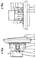
- FIG. 2 3rd are two side views of an electrical installation switch or - button shown (against each other rotated by 90 °), wherein in both representations of the electrical installation switch or button 1 each of the converter 18 is plugged (mounted) on the bottom side of the device socket / switch insert 4.
- the support ring 6 There are each of the support ring 6, the position of the terminals 5 including Klemmfederlösetasten, the spring struts 7, the cover 16 and the rocker 9 including light outlet 10 can be seen.
- the support ring 6 the position of the terminals 5 including Klemmfederlösetasten, the spring struts 7, the cover 16 and the rocker 9 including light outlet 10 can be seen.
- cover 17 which covers one of the two arranged on the bottom side of the device base / switch insert 4 switched outputs and engages with bolts 21 in the insertion openings for the lead wire, which is for the rotationally secure locking of the converter 18 on the device base / switching insert. 4 contributes.
- Fig. 4 is a view of the underside of an electrical installation switch or button shown. It can be seen that in spite of the mounted on the bottom side of the device base / switch insert 4 (mounted) converter 18 is given the free access to three of the four terminals 5, namely the terminal for the phase L, the terminal for the neutral conductor N and Terminal for a first switched output. The terminal for a second switched output is covered by the cover portion 17. Furthermore, the support ring 6 and the spring struts 7 of the device base / switch insert 4 and the over the support ring 6 cross-edge portion of the cover 16 of the electrical installation switch or button 1 are shown.
- Fig. 5 a lateral section through an electrical installation switch or push button is shown.
- an LED light-emitting means 13 is arranged.
- the LED illuminant 13 is electrically connected to the circuit board 11.
- the heat generated by the LED bulb 13 during operation heat dissipated to the outside atmosphere.
- Fig. 5 shows in particular the central bore of the device base / switching insert 4, in which both the sleeve 20 and the cylindrical portion of the contact part 22 dive. Furthermore, the support ring 6, the terminals 5 including clamping spring release buttons and the cover 16 of the installation switch or button can be seen.
- the LED illuminant 13 itself can consist of one LED or also of several LEDs, depending on which light intensity is desired.
- the installation switch or button can also be mounted rotated by 180 °, so that the light outlet 10 radiates towards the ceiling, resulting in a very bright, preferably white ceiling for reflection, whereby a desired floor lighting is realized.
- the invention can be used universally for arrangements in switch-off, changeover, cross-circuiting and key switches.
Description
Die Erfindung bezieht sich auf einen elektrischen Installationsschalter oder -taster mit Gerätesockel/Schalteinsatz mit Anschlussklemmen für Phase, Nulleiter und geschaltete Ausgänge sowie einer Wippe mit einem Lichtauslass für eine Beleuchtung in einer Seitenkante für den Einbau in eine handelsübliche UP-Gerätedose (insbesondere nach DIN 49073).The invention relates to an electrical installation switch or button with device base / switch insert with terminals for phase, neutral and switched outputs and a rocker with a light outlet for lighting in a side edge for installation in a standard flush-mounted box (especially according to DIN 49073 ).
Aus der
Aus der
Aus der
Der Erfindung liegt die Aufgabe zugrunde, einen hinsichtlich Energieeffizient und Lichtintensität optimierten elektrischen Installationsschalter oder -taster mit Gerätesockel / Schalteinsatz mit einer Wippe mit einem Lichtauslass für eine Beleuchtung anzugeben.The invention has for its object to provide an optimized in terms of energy efficiency and light intensity electrical installation switch or button with device base / switch insert with a rocker with a light outlet for lighting.
Diese Aufgabe wird in Verbindung mit den Merkmalen des Oberbegriffes des Anspruchs 1 erfindungsgemäß dadurch gelöst,
- dass ein Konverter an der Bodenseite des Gerätesockels / Schalteinsatzes montiert ist,
- dass der Konverter primärseitig zwei Anschlussklemmen respektive mit diesen Anschlussklemmen elektrisch verbundene Komponenten kontaktiert,
- dass ein LED-Leuchtmittel in der Wippe montiert ist und
- dass der Konverter sekundärseitig das LED-Leuchtmittel über ein Kontaktteil kontaktiert.
- that a converter is mounted on the bottom side of the device base / switch insert,
- that the converter contacts on the primary side two connection terminals or components which are electrically connected to these connection terminals,
- that an LED bulb is mounted in the rocker and
- the converter contacts the LED illuminant on the secondary side via a contact part.
Die mit der Erfindung erzielbaren Vorteile bestehen insbesondere darin, dass durch den direkten Einsatz des LED-Leuchtmittels in der Wippe eine im Vergleich zum bekannten Stand der Technik wesentlich höhere Lichtintensität bei gleichzeitig wesentlich erhöhtem Wirkungsgrad erzielbar ist. Der Weg zum Schalter ist derartig erhellt, dass z. B. auf dem Fußboden liegende Gegenstände sehr gut erkannt werden, wodurch eine Stolpergefahr wesentlich vermindert wird. Dabei können allgemein übliche Gerätesockel/Schalteinsätze verwendet werden, denen ein Konverter bodenseitig aufgesteckt wird. Lediglich die Wippe stellt ein neu zu entwickelndes, zu fertigendes und bereitzustellendes Bauteil dar. Die elektrische Kontaktierung zwischen dem LED-Leuchtmittel in der Wippe und dem Konverter erfolgt durch im Gerätesockel / Schalteinsatz geführte Kontaktierungsmittel, welche eine Demontage der Wippe (inklusive LED-Leuchtmittel) vom Gerätesockel / Schalteinsatz ermöglichen, ohne dass dabei vorher elektrische Leitungen zu lösen wären.The advantages which can be achieved with the invention are, in particular, that the direct use of the LED illuminant in the rocker achieves a significantly higher light intensity compared to the known state of the art, while at the same time substantially increasing the efficiency. The way to the switch is illuminated so that z. B. lying on the floor objects are very well recognized, which a risk of tripping is significantly reduced. In this case, common device base / switch inserts can be used, which a converter is attached to the bottom side. Only the rocker is a newly to be developed, to be manufactured and to be provided component. The electrical contact between the LED bulb in the rocker and the converter is carried out in the device base / switch insert contacting, which disassembly of the rocker (including LED bulbs) allow from the device base / switch insert, without that would be previously to solve electrical lines.
Eine Nachrüstung des Installationsschalters oder-tasters von einem Gerät ohne Beleuchtung oder von einem Gerät mit Orientierungsbeleuchtung zum vorgeschlagenen Gerät mit Beleuchtung zu einem späteren Zeitpunkt ist jederzeit problemlos und kostengünstig möglich, es ist lediglich die vorhandene Wippe gegen die vorgeschlagene Wippe mit Beleuchtung auszutauschen, ferner ist der Konverter auf die Bodenseite des Gerätesockels / Schalteinsatzes aufzustecken. Der Gerätesockel / Schalteinsatz ohne aufgesteckten Konverter entspricht exakt demjenigen Gerätesockel / Schalteinsatz, wie er für einen konventionellen Installationsschalter oder -taster auch verwendet wird.A retrofit of the installation switch or pushbutton from a device without lighting or a device with orientation lighting to the proposed device with lighting at a later date is always easily and inexpensively possible, it is only to replace the existing rocker against the proposed rocker with lighting, is also place the converter on the bottom side of the device base / switch insert. The device base / switch insert without plugged converter corresponds exactly to the device base / switch insert, as it is also used for a conventional installation switch or push button.
Dabei erfolgt durch entsprechende elektrische Verschaltung eine alternative Aktivierung des schalterinternen LED-Leuchtmittels und der vom Installationsschalter oder - taster geschalteten externen Beleuchtung, so dass bei ausgeschalteter externer Beleuchtung das schalterinterne LED-Leuchtmittel leuchtet und bei eingeschalteter externer Beleuchtung das schalterinterne LED-Leuchtmittel ausgeschaltet ist.This is done by appropriate electrical wiring, an alternative activation of the switch-internal LED bulb and switched from the installation switch or - external lighting, so that when the external lighting switched off, the switch's internal LED illuminator lights and switched on external lighting, the switch's internal LED light is off.
Beim Installationsschalter oder -taster ist durch gewünschte Auswahl der Wippe und des Abdeckrahmens eine formschöne Einbindung / Integration in ein Installationsgeräte -Programm respektive Schalter- und Steckdosenprogramm sowie eine Kombination mit weiteren Geräten, beispielsweise Schaltern / Tastern / Dimmern / Steckdosen dieses Schalter- und Steckdosenprogramms möglich.When installation switch or button is a desired integration of the rocker and the cover frame a beautiful integration / integration in an installation equipment program respectively switch and socket program and a combination with other devices, such as switches / buttons / dimmers / sockets this switch and socket program possible ,
Vorteilhafte Ausgestaltungen der Erfindung sind in den Unteransprüchen gekennzeichnet.Advantageous embodiments of the invention are characterized in the subclaims.
Die Erfindung wird nachstehend an Hand der in der Zeichnung dargestellten Ausführungsbeispiele erläutert. Es zeigen:
- Fig. 1
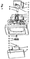
- eine perspektivische Sicht auf einen elektrischen Installationsschalter oder -taster in Form einer "Explosionszeichnung",
- Fig. 2, 3
- zwei Seitenansichten eines elektrischen Installationsschalters oder - tasters,
- Fig. 4
- eine Sicht auf die Unterseite eines elektrischen Installationsschalters oder -tasters,
- Fig. 5
- einen seitlichen Schnitt durch einen elektrischen Installationsschalter oder -taster.
- Fig. 1
- a perspective view of an electrical installation switch or button in the form of an "exploded view",
- Fig. 2, 3rd
- two side views of an electrical installation switch or button,
- Fig. 4
- a view of the underside of an electrical installation switch or pushbutton,
- Fig. 5
- a lateral section through an electrical installation switch or button.
In
- ein Gerätesockel /
Schalteinsatz 4, - eine
Wippe 9, - ein
Abdeckrahmen 16 und - ein Konverter 18 (Netzteil, LED-Treiber) inklusive Steuer- und Regeleinrichtung.
- a device base /
switch insert 4, - a
rocker 9, - a
cover frame 16 and - a converter 18 (power supply, LED driver) including control and regulating device.
Der für die Montage in eine handelsübliche UP-Gerätedose ausgebildete Gerätesockel / Schalteinsatz 4 weist wie allgemein üblich vier Anschlussklemmen 5 inklusive Klemmfederlösetasten auf, und zwar eine Anschlussklemme für die 230V-Phase L, eine Anschlussklemme für den Nulleiter N, eine Anschlussklemme für einen ersten geschalteten Ausgang und eine Anschlussklemme für einen zweiten geschalteten Ausgang, wobei wie allgemein üblich
- bei Spannungsbeaufschlagung (mit der Phase L) des ersten geschalteten Ausgangs am zweiten geschalteten Ausgang keine Spannung anliegt,
- bei Spannungsbeaufschlagung (mit der Phase L) des zweiten geschalteten Ausgangs am ersten geschalteten Ausgang keine Spannung anliegt.
- when voltage is applied (with the phase L) of the first switched output at the second switched output no voltage,
- voltage is applied to the first switched output when the voltage is applied (with the phase L) of the second switched output.
Des Weiteren besitzt der Gerätesockel / Schalteinsatz 4 selbstredend einen Tragring 6 und Federspreizen 7 zur Montage in der UP-Gerätedose.Furthermore, the device base /
Die Wippe 9 weist an ihrer bei montiertem Installationsschalter oder -taster vorzugsweise in Richtung Fußboden weisenden Seitenkante einen Lichtauslass 10, vorzugsweise inklusive optischer Linse auf, so dass der unterhalb des montierten Installationsschalters oder -tasters befindliche Fußboden erhellt wird. Für die Befestigung der Wippe 9 am Tragring 6 dienen Halteelemente 15.The
Der zur Versorgung eines nachfolgend näher beschriebenen LED-Leuchtmittels 13 (siehe hierzu
Beidseitig dieser Hülse 20 sind im Bereich des Gehäusebodens zwei Kontakte 19 für den Primäranschluss des Konverters 18 angeordnet. Diese beiden Kontakte 19 kontaktieren im montierten Zustand vorzugsweise zwei Kontakte im Boden des Gerätesockels / Schalteinsatzes 4 welche elektrisch mit den beiden Anschlussklemmen 5 für den Nulleiter N und für einen vom Abdeckabschnitt 17 abgedeckten zweiten geschalteten Ausgang verbunden sind.On both sides of this
Über den Innenraum der Hülse 20 erfolgt der Sekundäranschluss des Konverters 18 in Form eines zwischen Konverter 18 und Wippe 9 eingefügten Kontaktteils 22, welches
- einen zum Einführen in
die Hülse 20 geeigneten zylinderförmigen Abschnitt mit endseitigen Kontaktierungselementen 23 aufweist, welche den Sekundäranschluss des Konverters 18 elektrisch kontaktieren, - einen plattenförmigen
Abschnitt mit Kontaktflächen 24 aufweist, die mit korrespondierenden federnden Kontaktstiften 12einer Leiterplatte 11 elektrisch in Kontakt treten, welche an der Rückseite der Wippe 9 montiert ist.
- has a cylindrical portion suitable for insertion into the
sleeve 20 with end-side contacting elements 23, which electrically contact the secondary terminal of theconverter 18, - a plate-shaped portion having contact surfaces 24 which come into contact with corresponding resilient contact pins 12 of a printed
circuit board 11, which is mounted on the back of therocker 9.
In
In
In
Von Wichtigkeit ist die Stromführung von der Leiterplatte 11 über die federnden Kontaktstifte 12 und die Kontaktflächen 24 des Kontaktteils 22 mit seinen Kontaktierungselementen 23, welche mit hierzu korrespondierenden Kontakten der Hülse 20 des Konverters 18 in Kontakt treten. Der Konverter 18 wiederum wandelt die über seine Kontakte 19 vom Gerätesockel / Schalteinsatz 4 abgegriffene Netzwechselspannung in einen Konstant-Gleichstrom von z. B. 350 mA für die Speisung des LED-Leuchtmittels 13 um.Of importance is the current conduction from the printed
Das LED-Leuchtmittel 13 selbst kann aus einer LED oder auch aus mehreren LEDs bestehen, abhängig davon, welche Lichtintensität gewünscht wird.The
Selbstverständlich sind weitere Ausführungsvarianten mit alternativer Anordnung des LED-Leuchtmittels 13 innerhalb der Wippe 9 realisierbar. Wesentliches Kriterium bei allen Ausführungsvarianten ist die unmittelbare Integration des LED-Leuchtmittels 13 in der Wippe 9 selbst inklusive der zur Versorgung des LED-Leuchtmittels 13 erforderlichen Stromzuführung mit Kontaktteil 22, welches eine problemlose Demontage der Wippe 9 vom montierten Gerätesockel / Schalteinsatz 4 ermöglicht.Of course, further embodiments with alternative arrangement of the
Vorstehend ist die Rede davon, dass der Lichtauslass 10 vorzugsweise in Richtung Fußboden strahlt. Alternativ kann der Installationsschalter oder -taster auch um 180° gedreht montiert werden, so dass der Lichtauslass 10 in Richtung Decke strahlt, was bei einer sehr hellen, vorzugsweise weißen Decke zur Reflexion führt, wodurch eine gewünschte Fußbodenbeleuchtung realisiert wird.Above, there is talk of the
Selbstredend ist die Erfindung universell für Anordnungen in Ausschaltung, Wechselschaltung, Kreuzschaltung und bei Tastschaltern einsetzbar.Needless to say, the invention can be used universally for arrangements in switch-off, changeover, cross-circuiting and key switches.
- 11
- elektrischer Installationsschalter oder -tasterelectrical installation switch or button
- 22
- --
- 33
- --
- 44
- Gerätesockel / Schalteinsatz mit ZentralbohrungDevice base / switch insert with central bore
- 55
- Anschlussklemmen für 230V-Netzleitungen (L = Phase, N = Nulleiter, erster und zweiter geschalteter Ausgang) inklusive KlemmfederlösetastenTerminals for 230V power lines (L = phase, N = neutral, first and second switched output) including spring release buttons
- 66
- Tragringsupport ring
- 77
- FederspreizenFederspreizen
- 88th
- --
- 99
- Wippeseesaw
- 1010
- Lichtauslass inklusive optische LinseLight outlet including optical lens
- 1111
- Leiterplattecircuit board
- 1212
-
federnde Kontaktstifte zur Kontaktierung mit Kontaktflächen 24resilient contact pins for contacting with
contact surfaces 24 - 1313
- LED-Leuchtmittel (schalterintern)LED bulbs (internal switch)
- 1414
- Kühlkörper (Kühlblech)Heat sink (heat sink)
- 1515
- Halteelementretaining element
- 1616
- AbdeckrahmenCover
- 1717
- Abdeckabschnittcover
- 1818
- Konverter (Netzteil, LED-Treiber) inklusive Steuer-/RegeleinrichtungConverter (power supply, LED driver) including control unit
- 1919
- Kontakte für 230V-AnschlussContacts for 230V connection
- 2020
- Hülse zur Aufnahme der Leuchten-KontaktierungSleeve for holding the luminaire contacting
- 2121
-
Bolzen des Abdeckabschnitts 17Bolt of
cover 17 - 2222
- Kontaktteil mit zylinderförmigem AbschnittContact part with cylindrical section
- 2323
-
Kontaktierungselemente für Hülse 20 des Netzteils/Konverters 18Contacting elements for
sleeve 20 of the power supply /converter 18 - 2424
- Kontaktflächen für federnde Kontaktstifte 12Contact surfaces for resilient contact pins 12
Claims (8)
- Electrical installation switch or button (1) comprising a device base/switching insert (4) with connection terminals (5) for phase conductors, neutral conductors and switched outputs and also a rocker (9) with a light outlet (10) for illuminating a side edge,- wherein a power supply unit is mounted on the bottom side of the device base/switching insert (4),- wherein the power supply unit makes contact on the primary side with two connection terminals (5), or components which are electrically connected to the said connection terminals (5), by means of contacts (19),characterized- in that an LED lighting means (13) is mounted in the rocker (9), and- in that the power supply unit makes contact on the secondary side with the LED lighting means (13) by means of a contact part (22) which is inserted between the power supply unit and the rocker, wherein the contact part (22) has contact-making elements (23) which make electrical contact with the secondary connection of the converter (18), and- the contact part (22) has further contact areas (24) which come into electrical contact with corresponding spring-action contact pins (12) of a printed circuit board (11), wherein the printed circuit board (11) is mounted on the rear side of the rocker (9).
- Electrical installation switch or button (1) according to Claim 1, characterized in that contact is made with the LED lighting means (13) by means of spring-action contact pins (12) which interact with contact areas (24).
- Electrical installation switch or button (1) according to Claim 2, characterized in that the spring-action contact pins (12) are in the form of components of a printed circuit board (11) which is mounted on the rear side of the rocker (9).
- Electrical installation switch or button (1) according to Claim 2, characterized in that the spring-action contact pins (12) are in the form of components of a printed circuit board (11) which is mounted on the front side of the device base/switching insert (4).
- Electrical installation switch or button (1) according to one of the preceding claims, characterized in that the contact part (22) has a cylindrical section with contact-making elements (23), which cylindrical section engages into a sleeve (20) of the power supply unit in an electrically contact-making manner.
- Electrical installation switch or button (1) according to one of the preceding claims, characterized in that the power supply unit has a covering section (17) which firstly covers one of two connection terminals (5), which are arranged on the bottom of the device base/switching insert (4), of two switched outputs and which secondly makes electrical contact with this covered output.
- Electrical installation switch or button (1) according to Claim 6, characterized in that the covering section (17) has at least one bolt (21) which engages into the covered connection terminal (5) in a locking manner.
- Electrical installation switch or button (1) according to one of the preceding claims, characterized in that the rocker (9) has a heat sink (14) for dissipating the heat which is generated by the LED lighting means (13).
Applications Claiming Priority (1)
| Application Number | Priority Date | Filing Date | Title |
|---|---|---|---|
| DE102010005507A DE102010005507B4 (en) | 2010-01-23 | 2010-01-23 | Installation switch or push-button with a rocker with a light outlet for lighting |
Publications (3)
| Publication Number | Publication Date |
|---|---|
| EP2348522A2 EP2348522A2 (en) | 2011-07-27 |
| EP2348522A3 EP2348522A3 (en) | 2012-03-28 |
| EP2348522B1 true EP2348522B1 (en) | 2016-08-17 |
Family
ID=43899578
Family Applications (1)
| Application Number | Title | Priority Date | Filing Date |
|---|---|---|---|
| EP10014722.2A Not-in-force EP2348522B1 (en) | 2010-01-23 | 2010-11-18 | Installation switch or button with a rocker with a light outlet for a lighting device |
Country Status (7)
| Country | Link |
|---|---|
| EP (1) | EP2348522B1 (en) |
| CN (1) | CN102136379B (en) |
| DE (1) | DE102010005507B4 (en) |
| DK (1) | DK2348522T3 (en) |
| ES (1) | ES2603980T3 (en) |
| PL (1) | PL2348522T3 (en) |
| PT (1) | PT2348522T (en) |
Cited By (1)
| Publication number | Priority date | Publication date | Assignee | Title |
|---|---|---|---|---|
| CN106229203A (en) * | 2016-08-31 | 2016-12-14 | 乐清市鸿基贸易有限公司 | A kind of light modulating device |
Families Citing this family (7)
| Publication number | Priority date | Publication date | Assignee | Title |
|---|---|---|---|---|
| EP2654058B1 (en) * | 2012-04-20 | 2016-12-14 | Schneider Electric Industries SAS | Switch with lighting means and retrofittable electronic module |
| CN104867759A (en) * | 2015-04-27 | 2015-08-26 | 苏州贝腾特电子科技有限公司 | Remote electric operating mechanism for dual-power change-over switch of power distribution cabinet |
| CN104851704A (en) * | 2015-04-27 | 2015-08-19 | 苏州君丰辰电子科技有限公司 | Switching operation mechanism for dual-power switch of power transmission and distribution |
| CN104851634B (en) * | 2015-04-27 | 2017-08-25 | 吉林瑞科汉斯电气股份有限公司 | A kind of power switch |
| CN104851699A (en) * | 2015-04-27 | 2015-08-19 | 苏州君丰辰电子科技有限公司 | Integrated manual and electric switching operation mechanism |
| CN104867721A (en) * | 2015-04-27 | 2015-08-26 | 苏州君丰辰电子科技有限公司 | Switching operation mechanism for power transmission and distribution dual-power switch |
| CN104867723A (en) * | 2015-04-27 | 2015-08-26 | 苏州君丰辰电子科技有限公司 | Intelligent home power switch |
Family Cites Families (7)
| Publication number | Priority date | Publication date | Assignee | Title |
|---|---|---|---|---|
| DE20313428U1 (en) | 2003-08-29 | 2003-11-27 | Hoffmeister Leuchten Gmbh | Light, especially wall light, comprises mounting plate, circuit board with light diodes, light distribution panel and frame |
| DE102005008755B3 (en) * | 2005-02-25 | 2006-05-24 | Siemens Ag | Modular electrical installation switch with replaceable illumination unit has base module with recess on switch rocker side for accommodation of illumination unit as insert into recess |
| DE102006017915B3 (en) * | 2006-04-18 | 2007-08-02 | Albrecht Jung Gmbh & Co. Kg | Electric or electronic installation device for use in building system engineering, has covering frame and base fixed at supporting ring, illuminating device is fixed on base, and has printed circuit board with light emitting diode |
| DE102007001850B3 (en) | 2007-01-12 | 2008-02-14 | Abb Patent Gmbh | Illuminated installation switch for visibility in dark has rocker with light outlet aperture in side facing floor |
| DE102007018177B3 (en) * | 2007-04-18 | 2008-08-14 | Abb Ag | Plug socket with orientation lighting, particularly flush mounted-electric contact plug socket, has plate with plug socket pot and front side of central overlapping has assigned cover frame around predetermined dimension |
| DE102007045578B3 (en) * | 2007-09-24 | 2008-10-02 | Berker Gmbh & Co. Kg | Electrical switch has housing with fixed and movable contact parts that consists of upper part and base part and switching piece that is movably supported in housing |
| DE102008017653B4 (en) * | 2008-04-04 | 2010-02-25 | EVN Elektro-Vertrieb-Nürnberg GmbH | lighting device |
-
2010
- 2010-01-23 DE DE102010005507A patent/DE102010005507B4/en not_active Expired - Fee Related
- 2010-11-18 EP EP10014722.2A patent/EP2348522B1/en not_active Not-in-force
- 2010-11-18 PT PT100147222T patent/PT2348522T/en unknown
- 2010-11-18 ES ES10014722.2T patent/ES2603980T3/en active Active
- 2010-11-18 PL PL10014722T patent/PL2348522T3/en unknown
- 2010-11-18 DK DK10014722.2T patent/DK2348522T3/en active
-
2011
- 2011-01-14 CN CN201110022307.8A patent/CN102136379B/en not_active Expired - Fee Related
Cited By (1)
| Publication number | Priority date | Publication date | Assignee | Title |
|---|---|---|---|---|
| CN106229203A (en) * | 2016-08-31 | 2016-12-14 | 乐清市鸿基贸易有限公司 | A kind of light modulating device |
Also Published As
| Publication number | Publication date |
|---|---|
| PL2348522T3 (en) | 2017-03-31 |
| ES2603980T3 (en) | 2017-03-02 |
| DE102010005507B4 (en) | 2011-10-27 |
| PT2348522T (en) | 2016-11-24 |
| CN102136379B (en) | 2015-04-01 |
| EP2348522A2 (en) | 2011-07-27 |
| CN102136379A (en) | 2011-07-27 |
| DK2348522T3 (en) | 2016-12-12 |
| EP2348522A3 (en) | 2012-03-28 |
| DE102010005507A1 (en) | 2011-07-28 |
Similar Documents
| Publication | Publication Date | Title |
|---|---|---|
| EP2348522B1 (en) | Installation switch or button with a rocker with a light outlet for a lighting device | |
| DE102009016778B4 (en) | Concealed LED light | |
| EP2151899B1 (en) | Light strip system | |
| EP1610422B1 (en) | Electrical connecting device | |
| EP1983620B1 (en) | Socket with orientation lighting | |
| EP2850705B1 (en) | Support rail for holding and supplying power to a plurality of lighting modules, and light strip system with such a support rail | |
| EP2348792B1 (en) | Built-in LED lamp | |
| DE102009031586B3 (en) | Electrical installation equipment for building system engineering, has design cover and socket at which lighting device is connected, where lighting device has lamp and socket is provided with supporting ring | |
| EP2348249B1 (en) | Built-in LED | |
| EP2363634A2 (en) | Built-in LED light, in particular ceiling light | |
| DE10113240A1 (en) | Multipurpose elongate lighting unit has a modular structure, with its functional modules with standardized lateral dimensions not dependent on their length housed in elongate main and side profiles | |
| DE102011008507B3 (en) | Concealed LED light | |
| EP3527886A1 (en) | Electric light | |
| EP2187485B1 (en) | Electric socket | |
| DE102009031588B4 (en) | Electrical plug device | |
| DE102007024419A1 (en) | Lighting device with a rail device attachable to a surface of an object | |
| DE102018103379B3 (en) | Electric light | |
| DE102010005505B4 (en) | Flush-mounted LED light with support plate | |
| DE102007018178B4 (en) | Flush-mounted socket with illuminant module | |
| EP3680550B1 (en) | Light arrangement for an elongated lamp | |
| DE102018103375B3 (en) | Electric light | |
| DE102018103381B3 (en) | Electric light | |
| DE202016103954U1 (en) | Luminaire with two housing parts | |
| DE102006007019A1 (en) | Inspection light for visual inspection of e.g. difficult accessible part of e.g. vehicle, has cold cathode fluorescent lamp with diameter less than seven millimeter utilized as illuminant, where illuminant is arranged in protective tube | |
| DE102012103042B4 (en) | lighting arrangement |
Legal Events
| Date | Code | Title | Description |
|---|---|---|---|
| PUAI | Public reference made under article 153(3) epc to a published international application that has entered the european phase |
Free format text: ORIGINAL CODE: 0009012 |
|
| AK | Designated contracting states |
Kind code of ref document: A2 Designated state(s): AL AT BE BG CH CY CZ DE DK EE ES FI FR GB GR HR HU IE IS IT LI LT LU LV MC MK MT NL NO PL PT RO RS SE SI SK SM TR |
|
| AX | Request for extension of the european patent |
Extension state: BA ME |
|
| PUAL | Search report despatched |
Free format text: ORIGINAL CODE: 0009013 |
|
| AK | Designated contracting states |
Kind code of ref document: A3 Designated state(s): AL AT BE BG CH CY CZ DE DK EE ES FI FR GB GR HR HU IE IS IT LI LT LU LV MC MK MT NL NO PL PT RO RS SE SI SK SM TR |
|
| AX | Request for extension of the european patent |
Extension state: BA ME |
|
| RIC1 | Information provided on ipc code assigned before grant |
Ipc: H01H 23/02 20060101AFI20120217BHEP |
|
| 17P | Request for examination filed |
Effective date: 20120512 |
|
| 17Q | First examination report despatched |
Effective date: 20141215 |
|
| GRAP | Despatch of communication of intention to grant a patent |
Free format text: ORIGINAL CODE: EPIDOSNIGR1 |
|
| INTG | Intention to grant announced |
Effective date: 20160510 |
|
| GRAS | Grant fee paid |
Free format text: ORIGINAL CODE: EPIDOSNIGR3 |
|
| GRAA | (expected) grant |
Free format text: ORIGINAL CODE: 0009210 |
|
| AK | Designated contracting states |
Kind code of ref document: B1 Designated state(s): AL AT BE BG CH CY CZ DE DK EE ES FI FR GB GR HR HU IE IS IT LI LT LU LV MC MK MT NL NO PL PT RO RS SE SI SK SM TR |
|
| REG | Reference to a national code |
Ref country code: GB Ref legal event code: FG4D Free format text: NOT ENGLISH |
|
| REG | Reference to a national code |
Ref country code: CH Ref legal event code: EP |
|
| REG | Reference to a national code |
Ref country code: IE Ref legal event code: FG4D Free format text: LANGUAGE OF EP DOCUMENT: GERMAN |
|
| REG | Reference to a national code |
Ref country code: AT Ref legal event code: REF Ref document number: 821777 Country of ref document: AT Kind code of ref document: T Effective date: 20160915 |
|
| REG | Reference to a national code |
Ref country code: DE Ref legal event code: R096 Ref document number: 502010012197 Country of ref document: DE |
|
| REG | Reference to a national code |
Ref country code: FR Ref legal event code: PLFP Year of fee payment: 7 |
|
| REG | Reference to a national code |
Ref country code: NL Ref legal event code: FP |
|
| REG | Reference to a national code |
Ref country code: PT Ref legal event code: SC4A Ref document number: 2348522 Country of ref document: PT Date of ref document: 20161124 Kind code of ref document: T Free format text: AVAILABILITY OF NATIONAL TRANSLATION Effective date: 20161117 |
|
| REG | Reference to a national code |
Ref country code: SE Ref legal event code: TRGR |
|
| REG | Reference to a national code |
Ref country code: DK Ref legal event code: T3 Effective date: 20161208 |
|
| REG | Reference to a national code |
Ref country code: LT Ref legal event code: MG4D |
|
| REG | Reference to a national code |
Ref country code: NO Ref legal event code: T2 Effective date: 20160817 |
|
| PG25 | Lapsed in a contracting state [announced via postgrant information from national office to epo] |
Ref country code: RS Free format text: LAPSE BECAUSE OF FAILURE TO SUBMIT A TRANSLATION OF THE DESCRIPTION OR TO PAY THE FEE WITHIN THE PRESCRIBED TIME-LIMIT Effective date: 20160817 Ref country code: HR Free format text: LAPSE BECAUSE OF FAILURE TO SUBMIT A TRANSLATION OF THE DESCRIPTION OR TO PAY THE FEE WITHIN THE PRESCRIBED TIME-LIMIT Effective date: 20160817 Ref country code: LT Free format text: LAPSE BECAUSE OF FAILURE TO SUBMIT A TRANSLATION OF THE DESCRIPTION OR TO PAY THE FEE WITHIN THE PRESCRIBED TIME-LIMIT Effective date: 20160817 |
|
| PGFP | Annual fee paid to national office [announced via postgrant information from national office to epo] |
Ref country code: GB Payment date: 20161122 Year of fee payment: 7 Ref country code: LU Payment date: 20161121 Year of fee payment: 7 Ref country code: MC Payment date: 20161115 Year of fee payment: 7 Ref country code: CH Payment date: 20161121 Year of fee payment: 7 Ref country code: FR Payment date: 20161118 Year of fee payment: 7 Ref country code: IE Payment date: 20161122 Year of fee payment: 7 Ref country code: DE Payment date: 20161121 Year of fee payment: 7 Ref country code: IS Payment date: 20161019 Year of fee payment: 7 |
|
| PG25 | Lapsed in a contracting state [announced via postgrant information from national office to epo] |
Ref country code: LV Free format text: LAPSE BECAUSE OF FAILURE TO SUBMIT A TRANSLATION OF THE DESCRIPTION OR TO PAY THE FEE WITHIN THE PRESCRIBED TIME-LIMIT Effective date: 20160817 |
|
| PGFP | Annual fee paid to national office [announced via postgrant information from national office to epo] |
Ref country code: BE Payment date: 20161118 Year of fee payment: 7 Ref country code: PT Payment date: 20161123 Year of fee payment: 7 Ref country code: GR Payment date: 20161130 Year of fee payment: 7 Ref country code: IT Payment date: 20161129 Year of fee payment: 7 |
|
| REG | Reference to a national code |
Ref country code: GR Ref legal event code: EP Ref document number: 20160402870 Country of ref document: GR Effective date: 20170222 |
|
| PG25 | Lapsed in a contracting state [announced via postgrant information from national office to epo] |
Ref country code: RO Free format text: LAPSE BECAUSE OF FAILURE TO SUBMIT A TRANSLATION OF THE DESCRIPTION OR TO PAY THE FEE WITHIN THE PRESCRIBED TIME-LIMIT Effective date: 20160817 Ref country code: EE Free format text: LAPSE BECAUSE OF FAILURE TO SUBMIT A TRANSLATION OF THE DESCRIPTION OR TO PAY THE FEE WITHIN THE PRESCRIBED TIME-LIMIT Effective date: 20160817 |
|
| REG | Reference to a national code |
Ref country code: DE Ref legal event code: R097 Ref document number: 502010012197 Country of ref document: DE |
|
| PG25 | Lapsed in a contracting state [announced via postgrant information from national office to epo] |
Ref country code: SM Free format text: LAPSE BECAUSE OF FAILURE TO SUBMIT A TRANSLATION OF THE DESCRIPTION OR TO PAY THE FEE WITHIN THE PRESCRIBED TIME-LIMIT Effective date: 20160817 Ref country code: BG Free format text: LAPSE BECAUSE OF FAILURE TO SUBMIT A TRANSLATION OF THE DESCRIPTION OR TO PAY THE FEE WITHIN THE PRESCRIBED TIME-LIMIT Effective date: 20161117 Ref country code: SK Free format text: LAPSE BECAUSE OF FAILURE TO SUBMIT A TRANSLATION OF THE DESCRIPTION OR TO PAY THE FEE WITHIN THE PRESCRIBED TIME-LIMIT Effective date: 20160817 |
|
| PLBE | No opposition filed within time limit |
Free format text: ORIGINAL CODE: 0009261 |
|
| STAA | Information on the status of an ep patent application or granted ep patent |
Free format text: STATUS: NO OPPOSITION FILED WITHIN TIME LIMIT |
|
| 26N | No opposition filed |
Effective date: 20170518 |
|
| PG25 | Lapsed in a contracting state [announced via postgrant information from national office to epo] |
Ref country code: SI Free format text: LAPSE BECAUSE OF FAILURE TO SUBMIT A TRANSLATION OF THE DESCRIPTION OR TO PAY THE FEE WITHIN THE PRESCRIBED TIME-LIMIT Effective date: 20160817 |
|
| PG25 | Lapsed in a contracting state [announced via postgrant information from national office to epo] |
Ref country code: HU Free format text: LAPSE BECAUSE OF FAILURE TO SUBMIT A TRANSLATION OF THE DESCRIPTION OR TO PAY THE FEE WITHIN THE PRESCRIBED TIME-LIMIT; INVALID AB INITIO Effective date: 20101118 Ref country code: CY Free format text: LAPSE BECAUSE OF FAILURE TO SUBMIT A TRANSLATION OF THE DESCRIPTION OR TO PAY THE FEE WITHIN THE PRESCRIBED TIME-LIMIT Effective date: 20160817 |
|
| REG | Reference to a national code |
Ref country code: DE Ref legal event code: R119 Ref document number: 502010012197 Country of ref document: DE |
|
| PG25 | Lapsed in a contracting state [announced via postgrant information from national office to epo] |
Ref country code: MC Free format text: LAPSE BECAUSE OF NON-PAYMENT OF DUE FEES Effective date: 20171130 Ref country code: MK Free format text: LAPSE BECAUSE OF FAILURE TO SUBMIT A TRANSLATION OF THE DESCRIPTION OR TO PAY THE FEE WITHIN THE PRESCRIBED TIME-LIMIT Effective date: 20160817 Ref country code: TR Free format text: LAPSE BECAUSE OF FAILURE TO SUBMIT A TRANSLATION OF THE DESCRIPTION OR TO PAY THE FEE WITHIN THE PRESCRIBED TIME-LIMIT Effective date: 20160817 |
|
| GBPC | Gb: european patent ceased through non-payment of renewal fee |
Effective date: 20171118 |
|
| PG25 | Lapsed in a contracting state [announced via postgrant information from national office to epo] |
Ref country code: LI Free format text: LAPSE BECAUSE OF NON-PAYMENT OF DUE FEES Effective date: 20171130 Ref country code: CH Free format text: LAPSE BECAUSE OF NON-PAYMENT OF DUE FEES Effective date: 20171130 Ref country code: PT Free format text: LAPSE BECAUSE OF NON-PAYMENT OF DUE FEES Effective date: 20180518 |
|
| PG25 | Lapsed in a contracting state [announced via postgrant information from national office to epo] |
Ref country code: LU Free format text: LAPSE BECAUSE OF NON-PAYMENT OF DUE FEES Effective date: 20171118 Ref country code: GR Free format text: LAPSE BECAUSE OF NON-PAYMENT OF DUE FEES Effective date: 20180604 |
|
| REG | Reference to a national code |
Ref country code: FR Ref legal event code: ST Effective date: 20180731 Ref country code: BE Ref legal event code: MM Effective date: 20171130 |
|
| REG | Reference to a national code |
Ref country code: IE Ref legal event code: MM4A |
|
| PG25 | Lapsed in a contracting state [announced via postgrant information from national office to epo] |
Ref country code: MT Free format text: LAPSE BECAUSE OF FAILURE TO SUBMIT A TRANSLATION OF THE DESCRIPTION OR TO PAY THE FEE WITHIN THE PRESCRIBED TIME-LIMIT Effective date: 20160817 |
|
| PG25 | Lapsed in a contracting state [announced via postgrant information from national office to epo] |
Ref country code: FR Free format text: LAPSE BECAUSE OF NON-PAYMENT OF DUE FEES Effective date: 20171130 Ref country code: DE Free format text: LAPSE BECAUSE OF NON-PAYMENT OF DUE FEES Effective date: 20180602 Ref country code: IE Free format text: LAPSE BECAUSE OF NON-PAYMENT OF DUE FEES Effective date: 20171118 Ref country code: IT Free format text: LAPSE BECAUSE OF NON-PAYMENT OF DUE FEES Effective date: 20171118 Ref country code: AL Free format text: LAPSE BECAUSE OF FAILURE TO SUBMIT A TRANSLATION OF THE DESCRIPTION OR TO PAY THE FEE WITHIN THE PRESCRIBED TIME-LIMIT Effective date: 20160817 |
|
| PG25 | Lapsed in a contracting state [announced via postgrant information from national office to epo] |
Ref country code: GB Free format text: LAPSE BECAUSE OF NON-PAYMENT OF DUE FEES Effective date: 20171118 Ref country code: BE Free format text: LAPSE BECAUSE OF NON-PAYMENT OF DUE FEES Effective date: 20171130 |
|
| PGFP | Annual fee paid to national office [announced via postgrant information from national office to epo] |
Ref country code: NL Payment date: 20181120 Year of fee payment: 9 |
|
| PGFP | Annual fee paid to national office [announced via postgrant information from national office to epo] |
Ref country code: PL Payment date: 20181107 Year of fee payment: 9 Ref country code: NO Payment date: 20181126 Year of fee payment: 9 Ref country code: AT Payment date: 20181121 Year of fee payment: 9 Ref country code: CZ Payment date: 20181116 Year of fee payment: 9 Ref country code: DK Payment date: 20181122 Year of fee payment: 9 Ref country code: FI Payment date: 20181121 Year of fee payment: 9 Ref country code: SE Payment date: 20181120 Year of fee payment: 9 |
|
| PGFP | Annual fee paid to national office [announced via postgrant information from national office to epo] |
Ref country code: ES Payment date: 20181218 Year of fee payment: 9 |
|
| REG | Reference to a national code |
Ref country code: ES Ref legal event code: PC2A Owner name: ABB SCHWEIZ AG Effective date: 20190529 |
|
| REG | Reference to a national code |
Ref country code: NO Ref legal event code: CHAD Owner name: ABB SCHWEIZ AG, CH |
|
| REG | Reference to a national code |
Ref country code: NL Ref legal event code: PD Owner name: ABB SCHWEIZ AG; CH Free format text: DETAILS ASSIGNMENT: CHANGE OF OWNER(S), ASSIGNMENT; FORMER OWNER NAME: ABB AG Effective date: 20190926 |
|
| REG | Reference to a national code |
Ref country code: AT Ref legal event code: PC Ref document number: 821777 Country of ref document: AT Kind code of ref document: T Owner name: ABB SCHWEIZ AG, CH Effective date: 20190829 |
|
| REG | Reference to a national code |
Ref country code: FI Ref legal event code: MAE |
|
| REG | Reference to a national code |
Ref country code: DK Ref legal event code: EBP Effective date: 20191130 Ref country code: NO Ref legal event code: MMEP |
|
| REG | Reference to a national code |
Ref country code: SE Ref legal event code: EUG |
|
| REG | Reference to a national code |
Ref country code: NL Ref legal event code: MM Effective date: 20191201 |
|
| PG25 | Lapsed in a contracting state [announced via postgrant information from national office to epo] |
Ref country code: CZ Free format text: LAPSE BECAUSE OF NON-PAYMENT OF DUE FEES Effective date: 20191118 Ref country code: NO Free format text: LAPSE BECAUSE OF NON-PAYMENT OF DUE FEES Effective date: 20191130 Ref country code: FI Free format text: LAPSE BECAUSE OF NON-PAYMENT OF DUE FEES Effective date: 20191118 Ref country code: IS Free format text: LAPSE BECAUSE OF FAILURE TO SUBMIT A TRANSLATION OF THE DESCRIPTION OR TO PAY THE FEE WITHIN THE PRESCRIBED TIME-LIMIT Effective date: 20161217 |
|
| REG | Reference to a national code |
Ref country code: AT Ref legal event code: MM01 Ref document number: 821777 Country of ref document: AT Kind code of ref document: T Effective date: 20191118 |
|
| PG25 | Lapsed in a contracting state [announced via postgrant information from national office to epo] |
Ref country code: SE Free format text: LAPSE BECAUSE OF NON-PAYMENT OF DUE FEES Effective date: 20191119 |
|
| PG25 | Lapsed in a contracting state [announced via postgrant information from national office to epo] |
Ref country code: NL Free format text: LAPSE BECAUSE OF NON-PAYMENT OF DUE FEES Effective date: 20191201 |
|
| PG25 | Lapsed in a contracting state [announced via postgrant information from national office to epo] |
Ref country code: DK Free format text: LAPSE BECAUSE OF NON-PAYMENT OF DUE FEES Effective date: 20191130 |
|
| PG25 | Lapsed in a contracting state [announced via postgrant information from national office to epo] |
Ref country code: AT Free format text: LAPSE BECAUSE OF NON-PAYMENT OF DUE FEES Effective date: 20191118 |
|
| REG | Reference to a national code |
Ref country code: ES Ref legal event code: FD2A Effective date: 20210531 |
|
| PG25 | Lapsed in a contracting state [announced via postgrant information from national office to epo] |
Ref country code: ES Free format text: LAPSE BECAUSE OF NON-PAYMENT OF DUE FEES Effective date: 20191119 |
|
| PG25 | Lapsed in a contracting state [announced via postgrant information from national office to epo] |
Ref country code: PL Free format text: LAPSE BECAUSE OF NON-PAYMENT OF DUE FEES Effective date: 20191118 |