EP2187485B1 - Electric socket - Google Patents
Electric socket Download PDFInfo
- Publication number
- EP2187485B1 EP2187485B1 EP09014079.9A EP09014079A EP2187485B1 EP 2187485 B1 EP2187485 B1 EP 2187485B1 EP 09014079 A EP09014079 A EP 09014079A EP 2187485 B1 EP2187485 B1 EP 2187485B1
- Authority
- EP
- European Patent Office
- Prior art keywords
- light
- accordance
- electric socket
- central insert
- lighting element
- Prior art date
- Legal status (The legal status is an assumption and is not a legal conclusion. Google has not performed a legal analysis and makes no representation as to the accuracy of the status listed.)
- Active
Links
- 230000000295 complement effect Effects 0.000 claims description 4
- 230000001419 dependent effect Effects 0.000 claims description 4
- 229920003229 poly(methyl methacrylate) Polymers 0.000 claims description 2
- 239000004926 polymethyl methacrylate Substances 0.000 claims description 2
- 230000002093 peripheral effect Effects 0.000 description 9
- 238000009434 installation Methods 0.000 description 7
- 238000003780 insertion Methods 0.000 description 5
- 230000037431 insertion Effects 0.000 description 5
- 238000005286 illumination Methods 0.000 description 4
- 230000003287 optical effect Effects 0.000 description 4
- 230000000694 effects Effects 0.000 description 3
- 239000003550 marker Substances 0.000 description 3
- 230000011664 signaling Effects 0.000 description 3
- 230000000712 assembly Effects 0.000 description 2
- 238000000429 assembly Methods 0.000 description 2
- 238000009826 distribution Methods 0.000 description 2
- 230000001795 light effect Effects 0.000 description 2
- 230000005855 radiation Effects 0.000 description 2
- 230000004308 accommodation Effects 0.000 description 1
- 230000004913 activation Effects 0.000 description 1
- 230000006978 adaptation Effects 0.000 description 1
- 239000000853 adhesive Substances 0.000 description 1
- 230000001070 adhesive effect Effects 0.000 description 1
- 230000009286 beneficial effect Effects 0.000 description 1
- 238000000576 coating method Methods 0.000 description 1
- 238000005516 engineering process Methods 0.000 description 1
- 230000004313 glare Effects 0.000 description 1
- 230000010354 integration Effects 0.000 description 1
Images


Classifications
-
- H—ELECTRICITY
- H01—ELECTRIC ELEMENTS
- H01R—ELECTRICALLY-CONDUCTIVE CONNECTIONS; STRUCTURAL ASSOCIATIONS OF A PLURALITY OF MUTUALLY-INSULATED ELECTRICAL CONNECTING ELEMENTS; COUPLING DEVICES; CURRENT COLLECTORS
- H01R13/00—Details of coupling devices of the kinds covered by groups H01R12/70 or H01R24/00 - H01R33/00
- H01R13/66—Structural association with built-in electrical component
- H01R13/717—Structural association with built-in electrical component with built-in light source
-
- H—ELECTRICITY
- H01—ELECTRIC ELEMENTS
- H01R—ELECTRICALLY-CONDUCTIVE CONNECTIONS; STRUCTURAL ASSOCIATIONS OF A PLURALITY OF MUTUALLY-INSULATED ELECTRICAL CONNECTING ELEMENTS; COUPLING DEVICES; CURRENT COLLECTORS
- H01R24/00—Two-part coupling devices, or either of their cooperating parts, characterised by their overall structure
- H01R24/76—Two-part coupling devices, or either of their cooperating parts, characterised by their overall structure with sockets, clips or analogous contacts and secured to apparatus or structure, e.g. to a wall
-
- H—ELECTRICITY
- H01—ELECTRIC ELEMENTS
- H01R—ELECTRICALLY-CONDUCTIVE CONNECTIONS; STRUCTURAL ASSOCIATIONS OF A PLURALITY OF MUTUALLY-INSULATED ELECTRICAL CONNECTING ELEMENTS; COUPLING DEVICES; CURRENT COLLECTORS
- H01R2103/00—Two poles
Definitions
- the invention relates to an electrical socket according to the preamble of claim 1 (see. DE 10026256 A1 ).
- sockets are used to connect electrical consumers via a device connector releasably connected to a mains voltage.
- a socket is usually arranged stationary and includes a device base, the outside surrounds a support frame, which allows attachment in an installation housing.
- Front side, a front element is attached, which may be formed one or more parts depending on the embodiment.
- sockets can have optical signaling devices that can be integrated into the front element in various ways.
- a socket side of the device base on a signaling device with a glow lamp which emits light on the user side via a front-side window in a front element of the socket. Furthermore, a socket with lighting is disclosed, are arranged in the light-emitting diodes in the two contact holes for the pins of a device plug.
- bulbs which can be plugged as a compact body directly into a socket and on the side facing away from the electrical connections have light sources that illuminate as a marker light a room at least partially or used as an orientation light in a room.
- the object of the present invention is to provide an electrical socket, which has the lighting functions of external devices and which is formed at the same time compact and visually good.
- the invention according to claim 1 has the advantage that the integration of a lighting element in a socket no external devices for orientation in the room or to find the outlet are needed and thus the previous functionality of a socket is significantly improved.
- the insertion of a plug in unfavorable lighting conditions is facilitated and it is also the orientation in the room allows.
- the socket comprises a device base and a superior user-visible front element, wherein the front element has at least one pot-shaped central insert for receiving a device plug.
- at least one lighting element is arranged on or in the side wall of the cup-shaped central insert and radiates light into the central insert.
- the expense of creating Lichtaus- or - passages can be avoided in the often elaborately designed front elements and it can be a uninterrupted surface and compared to standard equipment especially the same appearance are maintained. This is desirable on the user side, especially for high-quality or sophisticated surfaces.
- the lighting elements can be integrated almost invisibly into the central insert and are located in a protected position, so that damage or tampering is not possible.
- the lighting element can radiate the light through a recess or a translucent area in the central insert.
- the light outlet or passage near a peripheral edge or near the upper edge of the central insert may be formed so that the emitted light remains visible even when the plug is plugged and continues to mark and orientation or illuminates the plug.
- the light can escape through the annular gap between the plug and the central insert which is still present when the plug is plugged in
- the light can be radiated radially into the central insert to allow uniform illumination and at the same time to clearly mark the receiving area for a device plug.
- the radiated light of the lighting element is directed against the bottom of the cup-shaped central insert, which serves as a reflection surface in this case, so that a concentration of the light rays takes place and at the same time any glare effects are avoided over a user.
- additional reflection means may be provided or formed on the central insert and / or on the lighting element in order to be able to direct the light emitted by the lighting element to defined locations of the central insert.
- the arrangement, number, shape, color and / or control of the lighting elements can be different light effects and / or distributions form, for example, figures, patterns, letters and / or characters.
- a marker or orientation light can be designed and in addition, an additional Information to be presented.
- the lighting element is understood as the element that radiates light into the central insert.
- the lighting element can be configured on the one hand as a light source or on the other hand as a light-conducting body.
- the lighting element and / or its support may be releasably attached to the central insert to allow replacement, if necessary.
- positive-locking receptacles can be provided in which optional complementary locking means provide additional fixation.
- non-detachable connections are possible, which can be made adhesive.
- the light can be generated by one or more light sources. If the light source is not itself the lighting element, it can be arranged interchangeably on the device base and on a support, such as a board, a socket or a housing, are.
- Light sources LEDs, OLEDs
- laser diodes laser diodes
- glow lamps cold cathode lamps
- incandescent lamps incandescent lamps
- EL film electroluminescent lamps
- the lighting element may be formed as a light-conducting body, in which the light is irradiated by a light source.
- the light-guiding body has the advantage that light-emitting surfaces can be arranged at positions which are unsuitable for the arrangement of a light source, for example.
- the light-conducting body allows a larger radiation area and an attractive design with respect to a light source. As the radiation an identical amount of light over a large area less glaring and dazzling, the use of a light-conducting body may be beneficial.
- the design of the emission area different light effects and / or distributions can be defined and chamfered and / or graduated emission areas can be provided.
- a plurality of light sources can illuminate a uniform optical waveguide extending around the socket.
- a further embodiment of the invention provides that only one light source illuminates a correspondingly graduated light guide ring.
- the light-conducting body can contain acrylic glass, whereby a predominantly reflective effect can be achieved by polished surfaces and a predominantly emitting effect by roughened surfaces.
- modular assemblies can be formed, for example, an electrical module with the power supply and an optical module with all lighting-relevant components or a light-generating module including power supply and light source and a lichtver tinydes module with the photoconductive and lichtabstrahlenden elements.
- one module can be arranged in the area of the device base and another module on the central insert.
- the modules can form self-contained assemblies, so that neither the device base nor the front element for their adaptation changes are necessary.
- the modules may preferably be releasably secured, but also permanent connections may be required. If a change in the number, location or type of light sources or other technical elements is necessary, this is made possible by the simple replacement of modules.
- the lighting elements can be controlled user, consumption, time, program or event-dependent, with a corresponding wireless or wired (bus) signal can intervene in the power supply of the light source.
- a manually operated command generator, z. As a switch and / or a button to be present at the socket.
- a twilight switch can be provided which activates the lighting of the socket only in insufficient light conditions.
- a motion detector can be provided which activates the lighting of the socket only in the presence of a person.
- activation of the lighting by further internal and / or external signal generator, for. B. by means of transponders.
- the lighting needs no energy to be supplied when the lighting is superfluous due to sufficient lighting conditions or non-use of rooms.
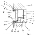
- the electrical socket 1 is mounted in an installation housing 2, which is fixed in a stationary building wall 3.
- the electrical socket 1 has a device base 4, which is fastened by means of a support frame 5 in the installation housing, which surrounds the device base 4 on the outside and which allows the attachment of the socket 1 in the installation housing 2.
- Front side is a function-specific front element 6 is attached, which may be one or more parts depending on the application.
- the front element 6 is provided with a cup-shaped central insert 7 for receiving a device plug, not shown, which has a perpendicular to the insertion bottom, at the right angles to the bottom circumferentially surrounding side wall 19 connects.
- terminals 8 and associated metallic contact elements are arranged, in the front side plug pins of the device plug can be inserted.
- a wall-side laid supply line 9 supplies the socket 1, for example, with a mains voltage, with individual lines are releasably fixed in the terminals 8.
- Fig. 1 and Fig. 2 Various electrical and / or optical components for realizing a lighting of the socket 1 in modules 10 and 11 are arranged.
- the two modules 10 and 11 communicate via interfaces 12 and 13 (FIG. Fig. 1 ), at which signals are transmitted from the first module 10 to the second module 11.
- the interfaces 12 and 13 are integrated into the housing body of the modules 10 and 11 and due to complementary shapes easily and unmistakably plugged into each other.
- plug contacts 16 interlock. Preferably, their connection is maintained under resilient force.
- the first module 10 is arranged at the front in a receiving space 17 of the device base 4.
- a removable cover (not shown) closes this receiving space 17, into which the module 10 designed to be complementary to the receiving space 17 can be inserted and locked in place.
- terminal contacts 18 are touch-protected out of the module 10, which are electrically contacted with the terminals 8 in the device base 4.
- the interface 12 On the upper side of the module 10 is the interface 12 in order to be able to conduct signals to the front element 6.
- the incoming electrical signals are converted into light signals.
- the module 11 comprises a carrier 24, for example a circuit board, with electrical components not shown in detail, and surrounds the central insert 7 both on the bottom side and in the region of the peripheral side wall 19.
- the module 11 is preferably made flat and on the central insert 7 form-fitting or lockable fixable.
- the interface 13 is guided in contact-protected manner with the plug contacts 16 out of the module 11, which is electrically contactable with the interface 12 of the first module 10 in the device base 4.
- At peripheral edges 20 of the second module 11 are lighting elements in the form of light sources 14, z.
- light-emitting diodes provided that dip after installation of the module 11 in the insertion direction radially extending recesses 21 of the side wall 19 of the central insert 7 and the user side preferably as orientation light or marker light serve.
- reflection means 25 in the form of reflective coatings, are applied in the recesses 21. Since the recesses 21 are formed in the region of the outer peripheral edge of the pot of the central insert 7 in the side wall 19, the light generated by the light sources 14 is visible through the annular gap between the plug and the central insert 7 even when plugged in the plug and continues to serve as lighting.
- a light source 22 preferably a light emitting diode, generates light.
- the light is radiated into an illumination element in the form of a light-conducting body 15 surrounding the central insert 7.
- Peripheral edges 23 of the light-conducting body 15 are angled at 90 ° perpendicular to the insertion direction and terminate in a radially surrounding the central insert 7 recess 21.
- the peripheral edges 23 are chamfered at their ends so that their end face extends at about 45 ° to the insertion direction to the To direct radiated light against the bottom of the central insert 7.
- a light source 22 in the form of a light emitting diode.
- the generated light is radiated into an illumination element 15 in the form of a light-conducting body 15 surrounding the central insert 7.
- the peripheral edges 23 of the light guide 15 are as in the embodiment of Fig. 2 angled and chamfered and end in a central insert 7 surrounding recess 21st
- the design of the light-conducting body 15 is not limited to a ring shape and may have any other shape, in particular to to produce a point or from points resulting illumination of the central insert 7.
- a programmable switching element 26 is arranged in the module 10, by which the lighting element 14 is controllable.
- the light source 22 is dependent on program data, eg. B. switching times, lighting conditions, supplied with power to illuminate the socket 1.
Description
Die Erfindung betrifft eine elektrische Steckdose nach dem Oberbegriff des Patentanspruches 1 (vgl.
Im Rahmen der Gebäudeinstallationstechnik werden elektrische Steckdosen dazu verwendet, elektrische Verbraucher über einen Gerätestecker lösbar an eine Netzspannung anzuschließen. Eine solche Steckdose ist dabei üblicherweise ortsfest angeordnet und umfasst einen Gerätesockel, den außenseitig ein Tragrahmen umgibt, der die Befestigung in einem Installationsgehäuse ermöglicht. Frontseitig ist ein Frontelement befestigt, das abhängig von der Ausführungsform ein- oder mehrteilig ausgebildet sein kann. Für besondere Anwendungen, beispielsweise um spezielle Funktionszustände anzuzeigen, können Steckdosen optische Signaleinrichtungen aufweisen, die in verschiedener Art und Weise in das Frontelement integriert sein können.As part of the building installation technology electrical sockets are used to connect electrical consumers via a device connector releasably connected to a mains voltage. Such a socket is usually arranged stationary and includes a device base, the outside surrounds a support frame, which allows attachment in an installation housing. Front side, a front element is attached, which may be formed one or more parts depending on the embodiment. For special applications, for example, to indicate special functional states, sockets can have optical signaling devices that can be integrated into the front element in various ways.
Bei einer bekannten Ausführungsform weist eine Steckdose seitlich des Gerätesockels eine Signaleinrichtung mit einer Glimmlampe auf, die über ein frontseitiges Fenster in einem Frontelement der Steckdose Licht nutzerseitig abstrahlt. Des Weiteren ist eine Steckdose mit Beleuchtung offenbart, bei der Leuchtdioden in den beiden Kontaktlöchem für die Kontaktstifte eines Gerätesteckers angeordnet sind.In a known embodiment, a socket side of the device base on a signaling device with a glow lamp, which emits light on the user side via a front-side window in a front element of the socket. Furthermore, a socket with lighting is disclosed, are arranged in the light-emitting diodes in the two contact holes for the pins of a device plug.
Darüber hinaus sind Leuchtmittel bekannt, die als kompakter Körper direkt in eine Steckdose eingesteckt werden können und die auf der den elektrischen Anschlüssen abgewandten Seite Lichtquellen aufweisen, die als Markierungsleuchte einen Raum zumindest teilweise beleuchten bzw. als Orientierungslicht in einem Raum verwendet werden.In addition, bulbs are known which can be plugged as a compact body directly into a socket and on the side facing away from the electrical connections have light sources that illuminate as a marker light a room at least partially or used as an orientation light in a room.
Die Aufgabe der vorliegenden Erfindung besteht darin, eine elektrische Steckdose zu schaffen, welche die Beleuchtungsfunktionen externer Geräte aufweist und die gleichzeitig kompakt und optisch gut wahrnehmbar ausgebildet ist.The object of the present invention is to provide an electrical socket, which has the lighting functions of external devices and which is formed at the same time compact and visually good.
Gelöst wird diese Aufgabe durch die im Patentanspruch 1 angegebenen Merkmale. Vorteilhafte Ausgestaltungen ergeben sich aus der Beschreibung, den Zeichnungen und den Unteransprüchen.This problem is solved by the features specified in
Die Erfindung gemäß Patentanspruch 1 weist den Vorteil auf, dass durch die Integration eines Beleuchtungselementes in eine Steckdose keine externen Geräte zur Orientierung im Raum oder zum Auffinden der Steckdose benötigt werden und somit die bisherige Funktionalität einer Steckdose deutlich verbessert wird. Das Einstecken eines Steckers bei ungünstigen Lichtverhältnissen wird erleichtert und es wird gleichzeitig die Orientierung im Raum ermöglicht.The invention according to
Die Steckdose umfasst einen Gerätesockel und ein vorgesetztes nutzerseitig sichtbares Frontelement, wobei das Frontelement zumindest einen topfförmigen Zentraleinsatz für die Aufnahme eines Gerätesteckers aufweist. Erfindungsgemäß ist mindestens ein Beleuchtungselement an oder in der Seitenwand des topfförmigen Zentraleinsatzes angeordnet und strahlt Licht in den Zentraleinsatz ein.The socket comprises a device base and a superior user-visible front element, wherein the front element has at least one pot-shaped central insert for receiving a device plug. According to the invention, at least one lighting element is arranged on or in the side wall of the cup-shaped central insert and radiates light into the central insert.
Erfindungsgemäß kann der Aufwand zur Erstellung von Lichtaus- oder - durchlässen bei den oft aufwendig gestalteten Frontelementen vermieden werden und es kann eine ununterbrochene Oberfläche und gegenüber Standardausstattungen insbesondere das gleiche Erscheinungsbild gewahrt werden. Gerade bei hochwertigen oder anspruchvoll gestalteten Oberflächen ist dies nutzerseitig erwünscht. Die Beleuchtungselemente können nahezu unsichtbar in den Zentraleinsatz integriert werden und befinden sich in einer geschützten Position, so dass Beschädigungen oder Manipulationen nicht möglich sind.According to the invention, the expense of creating Lichtaus- or - passages can be avoided in the often elaborately designed front elements and it can be a uninterrupted surface and compared to standard equipment especially the same appearance are maintained. This is desirable on the user side, especially for high-quality or sophisticated surfaces. The lighting elements can be integrated almost invisibly into the central insert and are located in a protected position, so that damage or tampering is not possible.
Das Beleuchtungselement kann das Licht durch eine Ausnehmung oder einen lichtdurchlässigen Bereich in den Zentraleinsatz einstrahlen. Dabei kann der Lichtaus- bzw. -durchlass nahe einer Randkante oder nahe der Oberkante des Zentraleinsatzes so ausgebildet sein, dass das abgestrahlte Licht auch bei gestecktem Stecker sichtbar bleibt und weiterhin der Markierung und Orientierung dient bzw. den Stecker beleuchtet. Hierbei kann das Licht durch den auch bei gestecktem Stecker noch vorhandenen Ringspalt zwischen Stecker und Zentraleinsatz austretenThe lighting element can radiate the light through a recess or a translucent area in the central insert. In this case, the light outlet or passage near a peripheral edge or near the upper edge of the central insert may be formed so that the emitted light remains visible even when the plug is plugged and continues to mark and orientation or illuminates the plug. Hereby, the light can escape through the annular gap between the plug and the central insert which is still present when the plug is plugged in
Das Licht kann radial in den Zentraleinsatz eingestrahlt werden, um eine gleichmäßige Ausleuchtung zu ermöglichen und gleichzeitig den Aufnahmebereich für einen Gerätestecker deutlich zu markieren. In einer vorteilhaften Ausgestaltung ist das abgestrahlte Licht des Beleuchtungselementes gegen den Boden des topfförmigen Zentraleinsatzes gerichtet, der in diesem Fall als Reflexionsfläche dient, so dass eine Konzentration der Lichtstrahlen erfolgt und gleichzeitig jegliche Blendeffekte gegenüber einem Nutzer vermieden werden. Vorteilhaft können jedoch auch andere Einstrahlgeometrien sein. Darüber hinaus können an dem Zentraleinsatz und/oder an dem Beleuchtungselement zusätzliche Reflexionseinrichtungen vorgesehen oder ausgebildet sein, um das von dem Beleuchtungselement abgestrahlte Licht an definierte Stellen des Zentraleinsatzes lenken zu können.The light can be radiated radially into the central insert to allow uniform illumination and at the same time to clearly mark the receiving area for a device plug. In an advantageous embodiment, the radiated light of the lighting element is directed against the bottom of the cup-shaped central insert, which serves as a reflection surface in this case, so that a concentration of the light rays takes place and at the same time any glare effects are avoided over a user. However, other Einstrahlgeometrien can be advantageous. In addition, additional reflection means may be provided or formed on the central insert and / or on the lighting element in order to be able to direct the light emitted by the lighting element to defined locations of the central insert.
Insbesondere durch die Anordnung, Anzahl, Form, Farbe und/oder Ansteuerung der Beleuchtungselemente lassen sich unterschiedliche Lichteffekte und/oder -verteilungen bilden, beispielsweise Figuren, Muster, Buchstaben und/oder Schriftzeichen. Einerseits kann so ein Markierungs- bzw. Orientierungslicht gestaltet werden und darüber hinaus kann eine zusätzliche Information dargestellt werden. Hierdurch lassen sich neben der reinen Beleuchtungsfunktion auch Anwendungen im Bereich der Darstellung von Information oder der bisher an anderer Stelle angeordneten Signalisierung von Zuständen, z. B. Alarme oder Überbelastungen, realisieren.In particular, by the arrangement, number, shape, color and / or control of the lighting elements can be different light effects and / or distributions form, for example, figures, patterns, letters and / or characters. On the one hand, such a marker or orientation light can be designed and in addition, an additional Information to be presented. In this way, in addition to the pure lighting function, applications in the area of the representation of information or the previously arranged elsewhere signaling of states, eg. As alarms or overloads realize.
Im Rahmen der Erfindung wird das Beleuchtungselement als das Element verstanden, das Licht in den Zentraleinsatz einstrahlt. Je nach Ausführung kann das Beleuchtungselement einerseits als Lichtquelle oder andererseits als lichtleitender Körper ausgestaltet sein. Das Beleuchtungselement und/oder dessen Träger kann lösbar an dem Zentraleinsatz befestigt sein, um im Bedarfsfall einen Austausch zu ermöglichen. Hierzu können formschlüssige Aufnahmen vorgesehen werden, in denen optional komplementäre Rastmittel eine zusätzliche Fixierung schaffen. In einer weiteren Ausführung sind jedoch auch unlösbare Verbindungen möglich, die klebend erfolgen können.In the context of the invention, the lighting element is understood as the element that radiates light into the central insert. Depending on the design, the lighting element can be configured on the one hand as a light source or on the other hand as a light-conducting body. The lighting element and / or its support may be releasably attached to the central insert to allow replacement, if necessary. For this purpose, positive-locking receptacles can be provided in which optional complementary locking means provide additional fixation. In a further embodiment, however, non-detachable connections are possible, which can be made adhesive.
Das Licht kann von einer oder von mehreren Lichtquellen erzeugt werden. Sofern die Lichtquelle nicht selbst das Beleuchtungselement ist, kann sie austauschbar am Gerätesockel angeordnet sein und sich auf einem Träger, beispielsweise einer Platine, einem Sockel oder einem Gehäuse, befinden. Als Lichtquellen können Leuchtdioden (LED's, OLED's), Laserdioden, Glimmlampen, Kaltkathodenlampen, Glühlampen und/oder elektrolumineszierende Lampen (EL-Folie) verwendet werden.The light can be generated by one or more light sources. If the light source is not itself the lighting element, it can be arranged interchangeably on the device base and on a support, such as a board, a socket or a housing, are. Light sources (LEDs, OLEDs), laser diodes, glow lamps, cold cathode lamps, incandescent lamps and / or electroluminescent lamps (EL film) can be used as light sources.
In einer vorteilhaften Ausgestaltung kann das Beleuchtungselement als lichtleitender Körper ausgebildet sein, in den das Licht von einer Lichtquelle eingestrahlt wird. Der lichtleitende Körper hat den Vorteil, dass Licht abstrahlende Flächen an Positionen angeordnet werden können, die beispielsweise für die Anordnung einer Lichtquelle ungeeignet sind. Darüber hinaus ermöglicht der lichtleitende Körper gegenüber einer Lichtquelle einen größeren Abstrahlbereich und ein ansprechendes Design. Da die Abstrahlung einer identischen Lichtmenge über eine große Fläche weniger grell und blendend empfunden wird, kann die Verwendung eines lichtleitenden Körpers von Vorteil sein. Insbesondere durch die Gestaltung des Abstrahlbereiches lassen sich unterschiedliche Lichteffekte und/oder - verteilungen definieren und es können angefaste und/oder abgestufte Abstrahlbereiche vorgesehen werden.In an advantageous embodiment, the lighting element may be formed as a light-conducting body, in which the light is irradiated by a light source. The light-guiding body has the advantage that light-emitting surfaces can be arranged at positions which are unsuitable for the arrangement of a light source, for example. In addition, the light-conducting body allows a larger radiation area and an attractive design with respect to a light source. As the radiation an identical amount of light over a large area less glaring and dazzling, the use of a light-conducting body may be beneficial. In particular, by the design of the emission area, different light effects and / or distributions can be defined and chamfered and / or graduated emission areas can be provided.
In einer weiteren Ausführung können mehrere Lichtquellen einen gleichmäßigen ringförmig um die Steckdose verlaufenden Lichtleiter ausleuchten. Eine weitere Ausgestaltung der Erfindung sieht vor, dass nur eine Lichtquelle einen entsprechend abgestuften Lichtleiterring ausleuchtet.In a further embodiment, a plurality of light sources can illuminate a uniform optical waveguide extending around the socket. A further embodiment of the invention provides that only one light source illuminates a correspondingly graduated light guide ring.
Der lichtleitende Körper kann Acrylglas enthalten, wobei durch polierte Flächen eine vorwiegend reflektierende Wirkung und durch angeraute Flächen eine vorwiegend emittierende Wirkung erzielt werden kann.The light-conducting body can contain acrylic glass, whereby a predominantly reflective effect can be achieved by polished surfaces and a predominantly emitting effect by roughened surfaces.
In einer vorteilhaften Ausgestaltung können modulare Baugruppen gebildet werden, beispielsweise ein elektrisches Modul mit der Spannungsversorgung und ein optisches Modul mit allen beleuchtungsrelevanten Bauelementen oder ein lichterzeugendes Modul einschließlich Spannungsversorgung und Lichtquelle und ein lichtverteilendes Modul mit den lichtleitenden und lichtabstrahlenden Elementen. In diesen Fällen kann ein Modul im Bereich des Gerätesockels und ein weiteres Modul an dem Zentraleinsatz angeordnet sein. Die Module können in sich geschlossene Baugruppen bilden, so dass weder am Gerätesockel noch an dem Frontelement für deren Adaption Veränderungen notwendig sind. Die Module können vorzugsweise lösbar befestigt werden, wobei jedoch auch unlösbare Verbindungen erforderlich sein können. Sofern eine Änderung in der Anzahl, dem Ort oder der Art der Lichtquellen oder sonstiger technischer Elemente notwendig ist, wird dies durch den einfachen Austausch von Modulen möglich.In an advantageous embodiment, modular assemblies can be formed, for example, an electrical module with the power supply and an optical module with all lighting-relevant components or a light-generating module including power supply and light source and a lichtverteilendes module with the photoconductive and lichtabstrahlenden elements. In these cases, one module can be arranged in the area of the device base and another module on the central insert. The modules can form self-contained assemblies, so that neither the device base nor the front element for their adaptation changes are necessary. The modules may preferably be releasably secured, but also permanent connections may be required. If a change in the number, location or type of light sources or other technical elements is necessary, this is made possible by the simple replacement of modules.
Vorteilhafterweise können die Beleuchtungselemente nutzer-, verbrauchs-, zeit-, programm- oder ereignisabhängig angesteuert werden sein, wobei ein entsprechendes drahtloses oder drahtgebundenes (Bus-)Signal in die Stromversorgung der Lichtquelle eingreifen kann. Dabei kann im einfachsten Fall ein manuell zu bedienender Befehlgeber, z. B. ein Schalter und/oder ein Taster, an der Steckdose vorhanden sein. In einer weiteren Ausführungsform kann ein Dämmerungsschalter vorgesehen sein, der die Beleuchtung der Steckdose erst bei unzureichenden Lichtverhältnissen aktiviert. In einer weiteren Ausführungsform kann ein Bewegungsmelder vorgesehen sein, der die Beleuchtung der Steckdose erst bei Anwesenheit einer Person aktiviert. Des Weiteren kann eine Aktivierung der Beleuchtung durch weitere interne und/oder externe Signalgeber, z. B. mittels Transponder, erfolgen. So braucht der Beleuchtung keine Energie zugeführt werden, wenn die Beleuchtung aufgrund ausreichender Lichtverhältnisse oder Nichtnutzung von Räumen überflüssig ist.Advantageously, the lighting elements can be controlled user, consumption, time, program or event-dependent, with a corresponding wireless or wired (bus) signal can intervene in the power supply of the light source. In the simplest case, a manually operated command generator, z. As a switch and / or a button to be present at the socket. In a further embodiment, a twilight switch can be provided which activates the lighting of the socket only in insufficient light conditions. In a further embodiment, a motion detector can be provided which activates the lighting of the socket only in the presence of a person. Furthermore, activation of the lighting by further internal and / or external signal generator, for. B. by means of transponders. Thus, the lighting needs no energy to be supplied when the lighting is superfluous due to sufficient lighting conditions or non-use of rooms.
Weitere Einzelheiten, Merkmale und Vorteile der Erfindung ergeben sich aus nachfolgender Beschreibung eines bevorzugten Ausführungsbeispieles anhand der Zeichnungen.Further details, features and advantages of the invention will become apparent from the following description of a preferred embodiment with reference to the drawings.
Es zeigen:
- Fig. 1
- eine schematische Darstellung eines Ausführungsbeispiels einer Steckdose;
- Fig. 2
- ein weiteres Ausführungsbeispiel; und
- Fig. 3
- ein weiteres Ausführungsbeispiel.
- Fig. 1
- a schematic representation of an embodiment of a socket;
- Fig. 2
- another embodiment; and
- Fig. 3
- another embodiment.
Gleiche oder gleichwirkende Bauteile sind in der nachfolgenden Beschreibung mit gleichen Bezugszeichen versehen.The same or equivalent components are provided in the following description with the same reference numerals.
Nachfolgend wird der Aufbau und die Funktionsweise einer erfindungsgemäßen elektrischen Steckdose 1 schematisch anhand von alternativen Ausführungsbeispielen näher beschrieben.Hereinafter, the structure and operation of an
Die elektrische Steckdose 1 ist in einem Installationsgehäuse 2 befestigt, welches ortsfest in einer Gebäudewand 3 fixiert ist. Die elektrische Steckdose 1 weist einen Gerätesockel 4 auf, der mittels eines Tragrahmens 5 in dem Installationsgehäuse befestigbar ist, der den Gerätesockel 4 außenseitig umgibt und der die Befestigung der Steckdose 1 in dem Installationsgehäuse 2 ermöglicht. Frontseitig ist ein funktionsspezifisches Frontelement 6 befestigt, das je nach Anwendung ein- oder mehrteilig sein kann. Das Frontelement 6 ist mit einem topfförmigen Zentraleinsatz 7 zur Aufnahme eines nicht dargestellten Gerätesteckers versehen, der einen senkrecht zur Einsteckrichtung verlaufenden Boden aufweist, an den sich rechtwinklig eine den Boden umfangsseitig umgebende Seitenwand 19 anschließt. In dem Gerätesockel 4 sind Anschlussklemmen 8 und damit verbundene metallische Kontaktelemente angeordnet, in die frontseitig Steckerstifte des Gerätesteckers gesteckt werden können. Eine wandseitig verlegte Versorgungsleitung 9 versorgt die Steckdose 1 beispielsweise mit einer Netzspannung, wobei einzelne Leitungen lösbar in den Anschlussklemmen 8 fixiert sind.The
Gemäß der
Das erste Modul 10 ist frontseitig in einem Aufnahmeraum 17 des Gerätesockels 4 angeordnet. Im unbestückten Zustand verschließt eine entfernbare Abdeckung (nicht dargestellt) diesen Aufnahmeraum 17, in den das komplementär zum Aufnahmeraum 17 ausgebildete Modul 10 einsetzbar und rastend fixierbar ist. Bodenseitig sind Anschlusskontakte 18 berührungsgeschützt aus dem Modul 10 geführt, die mit den Anschlussklemmen 8 in dem Gerätesockel 4 elektrisch kontaktierbar sind. Oberseitig des Moduls 10 befindet sich die Schnittstelle 12, um Signale an das Frontelement 6 leiten zu können.The
Gemäß
An Umfangsrändern 20 des zweiten Moduls 11 sind Beleuchtungselemente in Form von Lichtquellen 14, z. B. Leuchtdioden, vorgesehen, die nach der Montage des Moduls 11 in sich zur Einsteckrichtung radial erstreckenden Ausnehmungen 21 der Seitenwand 19 des Zentraleinsatzes 7 eintauchen und nutzerseitig vorzugsweise als Orientierungslicht bzw. Markierungslicht dienen. Um eine einwärts gerichtete und blendfreie Lichtfläche zu erhalten sind in den Ausnehmungen 21 Reflexionseinrichtungen 25, in Form von reflektierenden Beschichtungen, aufgebracht. Da die Ausnehmungen 21 im Bereich der äußeren Randkante des Topfes des Zentraleinsatzes 7 in der Seitenwand 19 ausgebildet sind, ist auch bei eingestecktem Stecker das durch die Lichtquellen 14 erzeugte Licht durch den Ringspalt zwischen Stecker und Zentraleinsatz 7 sichtbar und dient weiterhin als Beleuchtung.At
In dem Ausführungsbeispiel gemäß
In dem Ausführungsbeispiel gemäß
Die Ausgestaltung des lichtleitenden Körpers 15 ist nicht auf eine Ringform begrenzt und kann jede andere Form aufweisen, insbesondere um eine punktuelle bzw. aus Punkten sich ergebende Ausleuchtung des Zentraleinsatzes 7 zu erzeugen.The design of the light-conducting
Darüber hinaus ist in dem Modul 10 ein programmierbares Schaltelement 26 angeordnet, durch welches das Beleuchtungselement 14 ansteuerbar ist. Die Lichtquelle 22 wird in Abhängigkeit von Programmdaten, z. B. Schaltzeiten, Lichtverhältnissen, mit Spannung versorgt, um die Steckdose 1 zu beleuchten.In addition, a
- 11
- Steckdosesocket
- 22
- Installationsgehäuseinstallation Enclosures
- 33
- Gebäudewandbuilding wall
- 44
- Gerätesockeldevice base
- 55
- Tragrahmensupporting frame
- 66
- Frontelementfront element
- 77
- Zentraleinsatzcentral insert
- 88th
- Anschlussklemmenterminals
- 99
- Versorgungsleitungsupply line
- 1010
- Modulmodule
- 1111
- Modulmodule
- 1212
- Schnittstelleinterface
- 1313
- Schnittstelleinterface
- 1414
- Lichtquellelight source
- 1515
- Lichtleitender KörperLight-guiding body
- 1616
- Steckkontakteplug contacts
- 1717
- Aufnahmeraumaccommodation space
- 1818
- Anschlusskontakteterminals
- 1919
- SeitenwandSide wall
- 2020
- Umfangsrand (Modul)Peripheral edge (module)
- 2121
- Ausnehmungrecess
- 2222
- Lichtquellelight source
- 2323
- Umfangsrand LichtleiterPeripheral edge light guide
- 2424
- Trägercarrier
- 2525
- Reflexionseinrichtungreflection means
- 2626
- Schaltelementswitching element
Claims (15)
- An electric socket (1) for establishing a releasable connection to a plug, comprising a device base (4) and a front element (6) which is fastened at the front side and which has a cup-shaped central insert (7) having a surrounding wall (19), and having at least one lighting element (14, 15) from which light is irradiated into the central insert (7), characterized in that the lighting element (14, 15) is arranged at or in the side wall (19) of the central insert (7).
- An electric socket in accordance with claim 1, characterized in that the lighting element (14, 15) is arranged surrounding the central insert (7).
- An electric socket in accordance with one of the preceding claims, characterized in that the side wall (19) has at least one cut-out (21) and/or at least one light-permeable region.
- An electric socket in accordance with claim 3, characterized in that the cut-out (21) and/or the light-permeable region is formed proximal to the margin in the side wall (19) and is in particular formed close to a marginal edge of the central insert (7) such that the irradiated light also remains visible with a plugged-in plug and serves for the marking and orientation and illuminates the plug.
- An electric socket in accordance with any one of the preceding claims, characterized in that the lighting element (14, 15) and/or the central insert (7) has/have at least one reflection device (25).
- An electric socket in accordance with any one of the preceding claims, characterized in that the lighting element is designed as a light source (14, 22) or as a light-conducting body (15).
- An electric socket in accordance with claim 6, characterized in that the light-conducting body (15) contains acrylic glass.
- An electric socket in accordance with any one of the preceding claims, characterized in that the lighting element (14, 15) is releasably or non-releasably fastened to the central insert (7).
- An electric socket in accordance with any one of the preceding claims 6 to 8, characterized in that a light source (22) is arranged at the device base (4) and a light-conducting body (15) is arranged at the central insert (7).
- An electric socket in accordance with any one of the preceding claims, characterized in that the side wall (19) is surrounded in ring shape by a light-conducting body (15).
- An electric socket in accordance with any one of the preceding claims 6 to 10, characterized in that the light-conducting body (15) is configured as stepped.
- An electric socket in accordance with any one of the preceding claims, characterized in that the lighting element (14, 15) is controllable dependent on the user, the consumption, the time, the program and/or the event.
- An electric socket in accordance with any one of the preceding claims, characterized in that the lighting element (14, 15) is arranged in at least one module (10, 11).
- An electric socket in accordance with claim 13, characterized in that one module (10) is arranged at the device base (4) and one module (11) is arranged at the central insert (7).
- An electric socket in accordance with one of the preceding claims 13 or 14, characterized in that a plurality of modules (10, 11) are mechanically, electrically and/or optically connectable via complementary interfaces (12, 13).
Applications Claiming Priority (1)
| Application Number | Priority Date | Filing Date | Title |
|---|---|---|---|
| DE200810057204 DE102008057204A1 (en) | 2008-11-13 | 2008-11-13 | Electrical outlet |
Publications (3)
| Publication Number | Publication Date |
|---|---|
| EP2187485A2 EP2187485A2 (en) | 2010-05-19 |
| EP2187485A3 EP2187485A3 (en) | 2011-03-30 |
| EP2187485B1 true EP2187485B1 (en) | 2016-05-25 |
Family
ID=41491444
Family Applications (1)
| Application Number | Title | Priority Date | Filing Date |
|---|---|---|---|
| EP09014079.9A Active EP2187485B1 (en) | 2008-11-13 | 2009-11-10 | Electric socket |
Country Status (2)
| Country | Link |
|---|---|
| EP (1) | EP2187485B1 (en) |
| DE (1) | DE102008057204A1 (en) |
Cited By (1)
| Publication number | Priority date | Publication date | Assignee | Title |
|---|---|---|---|---|
| CN106329243A (en) * | 2016-11-07 | 2017-01-11 | 温州国好机电科技有限公司 | Built-in self-bouncing safety socket |
Families Citing this family (2)
| Publication number | Priority date | Publication date | Assignee | Title |
|---|---|---|---|---|
| CN106025731B (en) * | 2016-07-07 | 2018-01-23 | 温州国好机电科技有限公司 | A kind of built-in safety socket |
| CN105932497B (en) * | 2016-07-07 | 2018-01-19 | 温州国好机电科技有限公司 | A kind of bright ring safety socket and plug-assembly |
Family Cites Families (6)
| Publication number | Priority date | Publication date | Assignee | Title |
|---|---|---|---|---|
| DE19525843C1 (en) * | 1995-07-15 | 1996-07-11 | Telefunken Microelectron | Illuminated socket outlet e.g. for automobile cigarette lighter |
| DE19835297C1 (en) * | 1998-08-05 | 2000-05-25 | Gerhard Koehlke | Motor vehicle extension socket; has lighting arrangement in socket cover with light dispersion plate to illuminate interior of socket and plug to be inserted |
| DE10026256B4 (en) * | 2000-05-26 | 2007-03-08 | Osram Opto Semiconductors Gmbh | socket |
| DE202006006105U1 (en) * | 2006-04-15 | 2006-08-10 | Gira Giersiepen Gmbh & Co. Kg | Electric-installation device e.g. socket outlet for buildings, has central covering with integrated lighting device |
| DE202006006354U1 (en) * | 2006-04-20 | 2007-08-30 | Merten Gmbh & Co. Kg | Electrical installation device |
| DE102007018177B3 (en) * | 2007-04-18 | 2008-08-14 | Abb Ag | Plug socket with orientation lighting, particularly flush mounted-electric contact plug socket, has plate with plug socket pot and front side of central overlapping has assigned cover frame around predetermined dimension |
-
2008
- 2008-11-13 DE DE200810057204 patent/DE102008057204A1/en not_active Withdrawn
-
2009
- 2009-11-10 EP EP09014079.9A patent/EP2187485B1/en active Active
Cited By (2)
| Publication number | Priority date | Publication date | Assignee | Title |
|---|---|---|---|---|
| CN106329243A (en) * | 2016-11-07 | 2017-01-11 | 温州国好机电科技有限公司 | Built-in self-bouncing safety socket |
| CN106329243B (en) * | 2016-11-07 | 2018-07-31 | 温州国好机电科技有限公司 | Built-in eject safety socket |
Also Published As
| Publication number | Publication date |
|---|---|
| DE102008057204A1 (en) | 2010-05-20 |
| EP2187485A2 (en) | 2010-05-19 |
| EP2187485A3 (en) | 2011-03-30 |
Similar Documents
| Publication | Publication Date | Title |
|---|---|---|
| EP2361452B1 (en) | Electric installation appliance | |
| EP2151899B1 (en) | Light strip system | |
| EP1610422B1 (en) | Electrical connecting device | |
| EP1983620B1 (en) | Socket with orientation lighting | |
| EP2348522B1 (en) | Installation switch or button with a rocker with a light outlet for a lighting device | |
| EP2364520B1 (en) | Electric installation device | |
| EP2187485B1 (en) | Electric socket | |
| DE102007046818B4 (en) | Electrical outlet | |
| DE202017103604U1 (en) | lighting device | |
| EP2579398B1 (en) | Electric safety plug | |
| DE102008017541B4 (en) | Electrical installation device for flush mounting | |
| EP2202856B1 (en) | Electric installation device | |
| EP2518848B1 (en) | Frame for electrical installation device | |
| DE10234560B3 (en) | Cold light lamp partially embedded in light guide body and providing useful light component and decorative light component | |
| DE102009031588B4 (en) | Electrical plug device | |
| DE202008004681U1 (en) | Electrical installation device for flush mounting | |
| DE19908574B4 (en) | Functional element with a light-emitting diode that can be snapped into a command or signaling device | |
| DE102018103375B3 (en) | Electric light | |
| DE102018103381B3 (en) | Electric light | |
| DE202015004723U1 (en) | Illuminable display device | |
| DE202015106015U1 (en) | Light-emitting diode module and luminaire with at least one light-emitting diode module | |
| DE202020101397U1 (en) | lamp | |
| EP2910843A1 (en) | Lighting device | |
| EP2910846B1 (en) | Illumination unit and support structure for the same | |
| EP2511589A2 (en) | Lighting device, lighting body holder and lighting body for same |
Legal Events
| Date | Code | Title | Description |
|---|---|---|---|
| PUAI | Public reference made under article 153(3) epc to a published international application that has entered the european phase |
Free format text: ORIGINAL CODE: 0009012 |
|
| AK | Designated contracting states |
Kind code of ref document: A2 Designated state(s): AT BE BG CH CY CZ DE DK EE ES FI FR GB GR HR HU IE IS IT LI LT LU LV MC MK MT NL NO PL PT RO SE SI SK SM TR |
|
| AX | Request for extension of the european patent |
Extension state: AL BA RS |
|
| RIN1 | Information on inventor provided before grant (corrected) |
Inventor name: VICKTORIUS, RICHARD |
|
| PUAL | Search report despatched |
Free format text: ORIGINAL CODE: 0009013 |
|
| AK | Designated contracting states |
Kind code of ref document: A3 Designated state(s): AT BE BG CH CY CZ DE DK EE ES FI FR GB GR HR HU IE IS IT LI LT LU LV MC MK MT NL NO PL PT RO SE SI SK SM TR |
|
| AX | Request for extension of the european patent |
Extension state: AL BA RS |
|
| 17P | Request for examination filed |
Effective date: 20110930 |
|
| REG | Reference to a national code |
Ref country code: DE Ref legal event code: R079 Ref document number: 502009012613 Country of ref document: DE Free format text: PREVIOUS MAIN CLASS: H01R0024160000 Ipc: H01R0024760000 |
|
| RIC1 | Information provided on ipc code assigned before grant |
Ipc: H01R 24/76 20110101AFI20151016BHEP Ipc: H01R 13/717 20060101ALI20151016BHEP |
|
| GRAP | Despatch of communication of intention to grant a patent |
Free format text: ORIGINAL CODE: EPIDOSNIGR1 |
|
| INTG | Intention to grant announced |
Effective date: 20151204 |
|
| GRAS | Grant fee paid |
Free format text: ORIGINAL CODE: EPIDOSNIGR3 |
|
| GRAA | (expected) grant |
Free format text: ORIGINAL CODE: 0009210 |
|
| AK | Designated contracting states |
Kind code of ref document: B1 Designated state(s): AT BE BG CH CY CZ DE DK EE ES FI FR GB GR HR HU IE IS IT LI LT LU LV MC MK MT NL NO PL PT RO SE SI SK SM TR |
|
| REG | Reference to a national code |
Ref country code: GB Ref legal event code: FG4D Free format text: NOT ENGLISH |
|
| REG | Reference to a national code |
Ref country code: CH Ref legal event code: EP |
|
| REG | Reference to a national code |
Ref country code: IE Ref legal event code: FG4D Free format text: LANGUAGE OF EP DOCUMENT: GERMAN Ref country code: AT Ref legal event code: REF Ref document number: 803024 Country of ref document: AT Kind code of ref document: T Effective date: 20160615 |
|
| REG | Reference to a national code |
Ref country code: DE Ref legal event code: R096 Ref document number: 502009012613 Country of ref document: DE |
|
| RAP2 | Party data changed (patent owner data changed or rights of a patent transferred) |
Owner name: SCHNEIDER ELECTRIC INDUSTRIES SAS |
|
| REG | Reference to a national code |
Ref country code: SE Ref legal event code: TRGR |
|
| REG | Reference to a national code |
Ref country code: LT Ref legal event code: MG4D |
|
| REG | Reference to a national code |
Ref country code: NL Ref legal event code: MP Effective date: 20160525 |
|
| REG | Reference to a national code |
Ref country code: FR Ref legal event code: PLFP Year of fee payment: 8 |
|
| PG25 | Lapsed in a contracting state [announced via postgrant information from national office to epo] |
Ref country code: NL Free format text: LAPSE BECAUSE OF FAILURE TO SUBMIT A TRANSLATION OF THE DESCRIPTION OR TO PAY THE FEE WITHIN THE PRESCRIBED TIME-LIMIT Effective date: 20160525 Ref country code: FI Free format text: LAPSE BECAUSE OF FAILURE TO SUBMIT A TRANSLATION OF THE DESCRIPTION OR TO PAY THE FEE WITHIN THE PRESCRIBED TIME-LIMIT Effective date: 20160525 Ref country code: NO Free format text: LAPSE BECAUSE OF FAILURE TO SUBMIT A TRANSLATION OF THE DESCRIPTION OR TO PAY THE FEE WITHIN THE PRESCRIBED TIME-LIMIT Effective date: 20160825 Ref country code: LT Free format text: LAPSE BECAUSE OF FAILURE TO SUBMIT A TRANSLATION OF THE DESCRIPTION OR TO PAY THE FEE WITHIN THE PRESCRIBED TIME-LIMIT Effective date: 20160525 |
|
| PG25 | Lapsed in a contracting state [announced via postgrant information from national office to epo] |
Ref country code: HR Free format text: LAPSE BECAUSE OF FAILURE TO SUBMIT A TRANSLATION OF THE DESCRIPTION OR TO PAY THE FEE WITHIN THE PRESCRIBED TIME-LIMIT Effective date: 20160525 Ref country code: LV Free format text: LAPSE BECAUSE OF FAILURE TO SUBMIT A TRANSLATION OF THE DESCRIPTION OR TO PAY THE FEE WITHIN THE PRESCRIBED TIME-LIMIT Effective date: 20160525 Ref country code: ES Free format text: LAPSE BECAUSE OF FAILURE TO SUBMIT A TRANSLATION OF THE DESCRIPTION OR TO PAY THE FEE WITHIN THE PRESCRIBED TIME-LIMIT Effective date: 20160525 Ref country code: GR Free format text: LAPSE BECAUSE OF FAILURE TO SUBMIT A TRANSLATION OF THE DESCRIPTION OR TO PAY THE FEE WITHIN THE PRESCRIBED TIME-LIMIT Effective date: 20160826 Ref country code: PT Free format text: LAPSE BECAUSE OF FAILURE TO SUBMIT A TRANSLATION OF THE DESCRIPTION OR TO PAY THE FEE WITHIN THE PRESCRIBED TIME-LIMIT Effective date: 20160926 |
|
| PG25 | Lapsed in a contracting state [announced via postgrant information from national office to epo] |
Ref country code: IT Free format text: LAPSE BECAUSE OF FAILURE TO SUBMIT A TRANSLATION OF THE DESCRIPTION OR TO PAY THE FEE WITHIN THE PRESCRIBED TIME-LIMIT Effective date: 20160525 |
|
| PG25 | Lapsed in a contracting state [announced via postgrant information from national office to epo] |
Ref country code: RO Free format text: LAPSE BECAUSE OF FAILURE TO SUBMIT A TRANSLATION OF THE DESCRIPTION OR TO PAY THE FEE WITHIN THE PRESCRIBED TIME-LIMIT Effective date: 20160525 Ref country code: EE Free format text: LAPSE BECAUSE OF FAILURE TO SUBMIT A TRANSLATION OF THE DESCRIPTION OR TO PAY THE FEE WITHIN THE PRESCRIBED TIME-LIMIT Effective date: 20160525 Ref country code: DK Free format text: LAPSE BECAUSE OF FAILURE TO SUBMIT A TRANSLATION OF THE DESCRIPTION OR TO PAY THE FEE WITHIN THE PRESCRIBED TIME-LIMIT Effective date: 20160525 Ref country code: SK Free format text: LAPSE BECAUSE OF FAILURE TO SUBMIT A TRANSLATION OF THE DESCRIPTION OR TO PAY THE FEE WITHIN THE PRESCRIBED TIME-LIMIT Effective date: 20160525 Ref country code: CZ Free format text: LAPSE BECAUSE OF FAILURE TO SUBMIT A TRANSLATION OF THE DESCRIPTION OR TO PAY THE FEE WITHIN THE PRESCRIBED TIME-LIMIT Effective date: 20160525 |
|
| PG25 | Lapsed in a contracting state [announced via postgrant information from national office to epo] |
Ref country code: SM Free format text: LAPSE BECAUSE OF FAILURE TO SUBMIT A TRANSLATION OF THE DESCRIPTION OR TO PAY THE FEE WITHIN THE PRESCRIBED TIME-LIMIT Effective date: 20160525 Ref country code: PL Free format text: LAPSE BECAUSE OF FAILURE TO SUBMIT A TRANSLATION OF THE DESCRIPTION OR TO PAY THE FEE WITHIN THE PRESCRIBED TIME-LIMIT Effective date: 20160525 Ref country code: BE Free format text: LAPSE BECAUSE OF NON-PAYMENT OF DUE FEES Effective date: 20161130 |
|
| REG | Reference to a national code |
Ref country code: DE Ref legal event code: R097 Ref document number: 502009012613 Country of ref document: DE |
|
| PLBE | No opposition filed within time limit |
Free format text: ORIGINAL CODE: 0009261 |
|
| STAA | Information on the status of an ep patent application or granted ep patent |
Free format text: STATUS: NO OPPOSITION FILED WITHIN TIME LIMIT |
|
| 26N | No opposition filed |
Effective date: 20170228 |
|
| PG25 | Lapsed in a contracting state [announced via postgrant information from national office to epo] |
Ref country code: SI Free format text: LAPSE BECAUSE OF FAILURE TO SUBMIT A TRANSLATION OF THE DESCRIPTION OR TO PAY THE FEE WITHIN THE PRESCRIBED TIME-LIMIT Effective date: 20160525 |
|
| REG | Reference to a national code |
Ref country code: CH Ref legal event code: PL |
|
| GBPC | Gb: european patent ceased through non-payment of renewal fee |
Effective date: 20161110 |
|
| PG25 | Lapsed in a contracting state [announced via postgrant information from national office to epo] |
Ref country code: LI Free format text: LAPSE BECAUSE OF NON-PAYMENT OF DUE FEES Effective date: 20161130 Ref country code: CH Free format text: LAPSE BECAUSE OF NON-PAYMENT OF DUE FEES Effective date: 20161130 |
|
| REG | Reference to a national code |
Ref country code: IE Ref legal event code: MM4A |
|
| PG25 | Lapsed in a contracting state [announced via postgrant information from national office to epo] |
Ref country code: LU Free format text: LAPSE BECAUSE OF NON-PAYMENT OF DUE FEES Effective date: 20161130 |
|
| REG | Reference to a national code |
Ref country code: FR Ref legal event code: PLFP Year of fee payment: 9 |
|
| PG25 | Lapsed in a contracting state [announced via postgrant information from national office to epo] |
Ref country code: IE Free format text: LAPSE BECAUSE OF NON-PAYMENT OF DUE FEES Effective date: 20161110 Ref country code: GB Free format text: LAPSE BECAUSE OF NON-PAYMENT OF DUE FEES Effective date: 20161110 |
|
| REG | Reference to a national code |
Ref country code: AT Ref legal event code: MM01 Ref document number: 803024 Country of ref document: AT Kind code of ref document: T Effective date: 20161110 |
|
| PG25 | Lapsed in a contracting state [announced via postgrant information from national office to epo] |
Ref country code: AT Free format text: LAPSE BECAUSE OF NON-PAYMENT OF DUE FEES Effective date: 20161110 |
|
| REG | Reference to a national code |
Ref country code: BE Ref legal event code: MM Effective date: 20161130 |
|
| PG25 | Lapsed in a contracting state [announced via postgrant information from national office to epo] |
Ref country code: HU Free format text: LAPSE BECAUSE OF FAILURE TO SUBMIT A TRANSLATION OF THE DESCRIPTION OR TO PAY THE FEE WITHIN THE PRESCRIBED TIME-LIMIT; INVALID AB INITIO Effective date: 20091110 Ref country code: CY Free format text: LAPSE BECAUSE OF FAILURE TO SUBMIT A TRANSLATION OF THE DESCRIPTION OR TO PAY THE FEE WITHIN THE PRESCRIBED TIME-LIMIT Effective date: 20160525 |
|
| PG25 | Lapsed in a contracting state [announced via postgrant information from national office to epo] |
Ref country code: TR Free format text: LAPSE BECAUSE OF FAILURE TO SUBMIT A TRANSLATION OF THE DESCRIPTION OR TO PAY THE FEE WITHIN THE PRESCRIBED TIME-LIMIT Effective date: 20160525 Ref country code: MC Free format text: LAPSE BECAUSE OF FAILURE TO SUBMIT A TRANSLATION OF THE DESCRIPTION OR TO PAY THE FEE WITHIN THE PRESCRIBED TIME-LIMIT Effective date: 20160525 Ref country code: MK Free format text: LAPSE BECAUSE OF FAILURE TO SUBMIT A TRANSLATION OF THE DESCRIPTION OR TO PAY THE FEE WITHIN THE PRESCRIBED TIME-LIMIT Effective date: 20160525 Ref country code: IS Free format text: LAPSE BECAUSE OF FAILURE TO SUBMIT A TRANSLATION OF THE DESCRIPTION OR TO PAY THE FEE WITHIN THE PRESCRIBED TIME-LIMIT Effective date: 20160525 |
|
| PG25 | Lapsed in a contracting state [announced via postgrant information from national office to epo] |
Ref country code: BG Free format text: LAPSE BECAUSE OF FAILURE TO SUBMIT A TRANSLATION OF THE DESCRIPTION OR TO PAY THE FEE WITHIN THE PRESCRIBED TIME-LIMIT Effective date: 20160525 |
|
| PG25 | Lapsed in a contracting state [announced via postgrant information from national office to epo] |
Ref country code: MT Free format text: LAPSE BECAUSE OF FAILURE TO SUBMIT A TRANSLATION OF THE DESCRIPTION OR TO PAY THE FEE WITHIN THE PRESCRIBED TIME-LIMIT Effective date: 20160525 |
|
| REG | Reference to a national code |
Ref country code: FR Ref legal event code: PLFP Year of fee payment: 10 |
|
| PGFP | Annual fee paid to national office [announced via postgrant information from national office to epo] |
Ref country code: FR Payment date: 20230929 Year of fee payment: 15 |
|
| PGFP | Annual fee paid to national office [announced via postgrant information from national office to epo] |
Ref country code: SE Payment date: 20231002 Year of fee payment: 15 Ref country code: DE Payment date: 20230929 Year of fee payment: 15 |