EP2187485B1 - Prise électrique - Google Patents
Prise électrique Download PDFInfo
- Publication number
- EP2187485B1 EP2187485B1 EP09014079.9A EP09014079A EP2187485B1 EP 2187485 B1 EP2187485 B1 EP 2187485B1 EP 09014079 A EP09014079 A EP 09014079A EP 2187485 B1 EP2187485 B1 EP 2187485B1
- Authority
- EP
- European Patent Office
- Prior art keywords
- light
- accordance
- electric socket
- central insert
- lighting element
- Prior art date
- Legal status (The legal status is an assumption and is not a legal conclusion. Google has not performed a legal analysis and makes no representation as to the accuracy of the status listed.)
- Active
Links
- 230000000295 complement effect Effects 0.000 claims description 4
- 230000001419 dependent effect Effects 0.000 claims description 4
- 229920003229 poly(methyl methacrylate) Polymers 0.000 claims description 2
- 239000004926 polymethyl methacrylate Substances 0.000 claims description 2
- 230000002093 peripheral effect Effects 0.000 description 9
- 238000009434 installation Methods 0.000 description 7
- 238000003780 insertion Methods 0.000 description 5
- 230000037431 insertion Effects 0.000 description 5
- 238000005286 illumination Methods 0.000 description 4
- 230000003287 optical effect Effects 0.000 description 4
- 230000000694 effects Effects 0.000 description 3
- 239000003550 marker Substances 0.000 description 3
- 230000011664 signaling Effects 0.000 description 3
- 230000000712 assembly Effects 0.000 description 2
- 238000000429 assembly Methods 0.000 description 2
- 238000009826 distribution Methods 0.000 description 2
- 230000001795 light effect Effects 0.000 description 2
- 230000005855 radiation Effects 0.000 description 2
- 230000004308 accommodation Effects 0.000 description 1
- 230000004913 activation Effects 0.000 description 1
- 230000006978 adaptation Effects 0.000 description 1
- 239000000853 adhesive Substances 0.000 description 1
- 230000001070 adhesive effect Effects 0.000 description 1
- 230000009286 beneficial effect Effects 0.000 description 1
- 238000000576 coating method Methods 0.000 description 1
- 238000005516 engineering process Methods 0.000 description 1
- 230000004313 glare Effects 0.000 description 1
- 230000010354 integration Effects 0.000 description 1
Images


Classifications
-
- H—ELECTRICITY
- H01—ELECTRIC ELEMENTS
- H01R—ELECTRICALLY-CONDUCTIVE CONNECTIONS; STRUCTURAL ASSOCIATIONS OF A PLURALITY OF MUTUALLY-INSULATED ELECTRICAL CONNECTING ELEMENTS; COUPLING DEVICES; CURRENT COLLECTORS
- H01R13/00—Details of coupling devices of the kinds covered by groups H01R12/70 or H01R24/00 - H01R33/00
- H01R13/66—Structural association with built-in electrical component
- H01R13/717—Structural association with built-in electrical component with built-in light source
-
- H—ELECTRICITY
- H01—ELECTRIC ELEMENTS
- H01R—ELECTRICALLY-CONDUCTIVE CONNECTIONS; STRUCTURAL ASSOCIATIONS OF A PLURALITY OF MUTUALLY-INSULATED ELECTRICAL CONNECTING ELEMENTS; COUPLING DEVICES; CURRENT COLLECTORS
- H01R24/00—Two-part coupling devices, or either of their cooperating parts, characterised by their overall structure
- H01R24/76—Two-part coupling devices, or either of their cooperating parts, characterised by their overall structure with sockets, clips or analogous contacts and secured to apparatus or structure, e.g. to a wall
-
- H—ELECTRICITY
- H01—ELECTRIC ELEMENTS
- H01R—ELECTRICALLY-CONDUCTIVE CONNECTIONS; STRUCTURAL ASSOCIATIONS OF A PLURALITY OF MUTUALLY-INSULATED ELECTRICAL CONNECTING ELEMENTS; COUPLING DEVICES; CURRENT COLLECTORS
- H01R2103/00—Two poles
Definitions
- the invention relates to an electrical socket according to the preamble of claim 1 (see. DE 10026256 A1 ).
- sockets are used to connect electrical consumers via a device connector releasably connected to a mains voltage.
- a socket is usually arranged stationary and includes a device base, the outside surrounds a support frame, which allows attachment in an installation housing.
- Front side, a front element is attached, which may be formed one or more parts depending on the embodiment.
- sockets can have optical signaling devices that can be integrated into the front element in various ways.
- a socket side of the device base on a signaling device with a glow lamp which emits light on the user side via a front-side window in a front element of the socket. Furthermore, a socket with lighting is disclosed, are arranged in the light-emitting diodes in the two contact holes for the pins of a device plug.
- bulbs which can be plugged as a compact body directly into a socket and on the side facing away from the electrical connections have light sources that illuminate as a marker light a room at least partially or used as an orientation light in a room.
- the object of the present invention is to provide an electrical socket, which has the lighting functions of external devices and which is formed at the same time compact and visually good.
- the invention according to claim 1 has the advantage that the integration of a lighting element in a socket no external devices for orientation in the room or to find the outlet are needed and thus the previous functionality of a socket is significantly improved.
- the insertion of a plug in unfavorable lighting conditions is facilitated and it is also the orientation in the room allows.
- the socket comprises a device base and a superior user-visible front element, wherein the front element has at least one pot-shaped central insert for receiving a device plug.
- at least one lighting element is arranged on or in the side wall of the cup-shaped central insert and radiates light into the central insert.
- the expense of creating Lichtaus- or - passages can be avoided in the often elaborately designed front elements and it can be a uninterrupted surface and compared to standard equipment especially the same appearance are maintained. This is desirable on the user side, especially for high-quality or sophisticated surfaces.
- the lighting elements can be integrated almost invisibly into the central insert and are located in a protected position, so that damage or tampering is not possible.
- the lighting element can radiate the light through a recess or a translucent area in the central insert.
- the light outlet or passage near a peripheral edge or near the upper edge of the central insert may be formed so that the emitted light remains visible even when the plug is plugged and continues to mark and orientation or illuminates the plug.
- the light can escape through the annular gap between the plug and the central insert which is still present when the plug is plugged in
- the light can be radiated radially into the central insert to allow uniform illumination and at the same time to clearly mark the receiving area for a device plug.
- the radiated light of the lighting element is directed against the bottom of the cup-shaped central insert, which serves as a reflection surface in this case, so that a concentration of the light rays takes place and at the same time any glare effects are avoided over a user.
- additional reflection means may be provided or formed on the central insert and / or on the lighting element in order to be able to direct the light emitted by the lighting element to defined locations of the central insert.
- the arrangement, number, shape, color and / or control of the lighting elements can be different light effects and / or distributions form, for example, figures, patterns, letters and / or characters.
- a marker or orientation light can be designed and in addition, an additional Information to be presented.
- the lighting element is understood as the element that radiates light into the central insert.
- the lighting element can be configured on the one hand as a light source or on the other hand as a light-conducting body.
- the lighting element and / or its support may be releasably attached to the central insert to allow replacement, if necessary.
- positive-locking receptacles can be provided in which optional complementary locking means provide additional fixation.
- non-detachable connections are possible, which can be made adhesive.
- the light can be generated by one or more light sources. If the light source is not itself the lighting element, it can be arranged interchangeably on the device base and on a support, such as a board, a socket or a housing, are.
- Light sources LEDs, OLEDs
- laser diodes laser diodes
- glow lamps cold cathode lamps
- incandescent lamps incandescent lamps
- EL film electroluminescent lamps
- the lighting element may be formed as a light-conducting body, in which the light is irradiated by a light source.
- the light-guiding body has the advantage that light-emitting surfaces can be arranged at positions which are unsuitable for the arrangement of a light source, for example.
- the light-conducting body allows a larger radiation area and an attractive design with respect to a light source. As the radiation an identical amount of light over a large area less glaring and dazzling, the use of a light-conducting body may be beneficial.
- the design of the emission area different light effects and / or distributions can be defined and chamfered and / or graduated emission areas can be provided.
- a plurality of light sources can illuminate a uniform optical waveguide extending around the socket.
- a further embodiment of the invention provides that only one light source illuminates a correspondingly graduated light guide ring.
- the light-conducting body can contain acrylic glass, whereby a predominantly reflective effect can be achieved by polished surfaces and a predominantly emitting effect by roughened surfaces.
- modular assemblies can be formed, for example, an electrical module with the power supply and an optical module with all lighting-relevant components or a light-generating module including power supply and light source and a lichtver tinydes module with the photoconductive and lichtabstrahlenden elements.
- one module can be arranged in the area of the device base and another module on the central insert.
- the modules can form self-contained assemblies, so that neither the device base nor the front element for their adaptation changes are necessary.
- the modules may preferably be releasably secured, but also permanent connections may be required. If a change in the number, location or type of light sources or other technical elements is necessary, this is made possible by the simple replacement of modules.
- the lighting elements can be controlled user, consumption, time, program or event-dependent, with a corresponding wireless or wired (bus) signal can intervene in the power supply of the light source.
- a manually operated command generator, z. As a switch and / or a button to be present at the socket.
- a twilight switch can be provided which activates the lighting of the socket only in insufficient light conditions.
- a motion detector can be provided which activates the lighting of the socket only in the presence of a person.
- activation of the lighting by further internal and / or external signal generator, for. B. by means of transponders.
- the lighting needs no energy to be supplied when the lighting is superfluous due to sufficient lighting conditions or non-use of rooms.
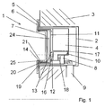
- the electrical socket 1 is mounted in an installation housing 2, which is fixed in a stationary building wall 3.
- the electrical socket 1 has a device base 4, which is fastened by means of a support frame 5 in the installation housing, which surrounds the device base 4 on the outside and which allows the attachment of the socket 1 in the installation housing 2.
- Front side is a function-specific front element 6 is attached, which may be one or more parts depending on the application.
- the front element 6 is provided with a cup-shaped central insert 7 for receiving a device plug, not shown, which has a perpendicular to the insertion bottom, at the right angles to the bottom circumferentially surrounding side wall 19 connects.
- terminals 8 and associated metallic contact elements are arranged, in the front side plug pins of the device plug can be inserted.
- a wall-side laid supply line 9 supplies the socket 1, for example, with a mains voltage, with individual lines are releasably fixed in the terminals 8.
- Fig. 1 and Fig. 2 Various electrical and / or optical components for realizing a lighting of the socket 1 in modules 10 and 11 are arranged.
- the two modules 10 and 11 communicate via interfaces 12 and 13 (FIG. Fig. 1 ), at which signals are transmitted from the first module 10 to the second module 11.
- the interfaces 12 and 13 are integrated into the housing body of the modules 10 and 11 and due to complementary shapes easily and unmistakably plugged into each other.
- plug contacts 16 interlock. Preferably, their connection is maintained under resilient force.
- the first module 10 is arranged at the front in a receiving space 17 of the device base 4.
- a removable cover (not shown) closes this receiving space 17, into which the module 10 designed to be complementary to the receiving space 17 can be inserted and locked in place.
- terminal contacts 18 are touch-protected out of the module 10, which are electrically contacted with the terminals 8 in the device base 4.
- the interface 12 On the upper side of the module 10 is the interface 12 in order to be able to conduct signals to the front element 6.
- the incoming electrical signals are converted into light signals.
- the module 11 comprises a carrier 24, for example a circuit board, with electrical components not shown in detail, and surrounds the central insert 7 both on the bottom side and in the region of the peripheral side wall 19.
- the module 11 is preferably made flat and on the central insert 7 form-fitting or lockable fixable.
- the interface 13 is guided in contact-protected manner with the plug contacts 16 out of the module 11, which is electrically contactable with the interface 12 of the first module 10 in the device base 4.
- At peripheral edges 20 of the second module 11 are lighting elements in the form of light sources 14, z.
- light-emitting diodes provided that dip after installation of the module 11 in the insertion direction radially extending recesses 21 of the side wall 19 of the central insert 7 and the user side preferably as orientation light or marker light serve.
- reflection means 25 in the form of reflective coatings, are applied in the recesses 21. Since the recesses 21 are formed in the region of the outer peripheral edge of the pot of the central insert 7 in the side wall 19, the light generated by the light sources 14 is visible through the annular gap between the plug and the central insert 7 even when plugged in the plug and continues to serve as lighting.
- a light source 22 preferably a light emitting diode, generates light.
- the light is radiated into an illumination element in the form of a light-conducting body 15 surrounding the central insert 7.
- Peripheral edges 23 of the light-conducting body 15 are angled at 90 ° perpendicular to the insertion direction and terminate in a radially surrounding the central insert 7 recess 21.
- the peripheral edges 23 are chamfered at their ends so that their end face extends at about 45 ° to the insertion direction to the To direct radiated light against the bottom of the central insert 7.
- a light source 22 in the form of a light emitting diode.
- the generated light is radiated into an illumination element 15 in the form of a light-conducting body 15 surrounding the central insert 7.
- the peripheral edges 23 of the light guide 15 are as in the embodiment of Fig. 2 angled and chamfered and end in a central insert 7 surrounding recess 21st
- the design of the light-conducting body 15 is not limited to a ring shape and may have any other shape, in particular to to produce a point or from points resulting illumination of the central insert 7.
- a programmable switching element 26 is arranged in the module 10, by which the lighting element 14 is controllable.
- the light source 22 is dependent on program data, eg. B. switching times, lighting conditions, supplied with power to illuminate the socket 1.
Claims (15)
- Prise électrique femelle (1) pour établir une liaison détachable avec une prise mâle, incluant un socle (4) et un élément frontal (6) fixé du côté frontal et qui comprend un insert central (7) en forme de godet et avec une paroi latérale qui l'entoure, comprenant au moins un élément d'éclairage (14, 15) depuis lequel de la lumière est envoyée jusque dans l'insert central (7),
caractérisée en ce que l'élément d'éclairage (14, 15) est agencé sur ou dans la paroi latérale (19) de l'insert central (7). - Prise électrique femelle selon la revendication 1, caractérisée en ce que l'élément d'éclairage (14, 15) est agencé de manière à entourer l'insert central (7).
- Prise électrique femelle selon l'une des revendications précédentes, caractérisée en ce que la paroi latérale (19) comporte au moins un évidement (21) et/ou au moins une zone laissant passer la lumière.
- Prise électrique femelle selon la revendication 3, caractérisée en ce que l'évidement (21) et/ou la zone laissant passer la lumière est réalisé dans la paroi latérale (19) à proximité de la bordure, et en particulier à proximité d'une arête de bordure de l'insert central (7) de telle façon que la lumière émise reste visible également lorsque la prise mâle est enfichée, et sert au marquage et à l'orientation, et éclaire la prise mâle.
- Prise électrique femelle selon l'une des revendications précédentes, caractérisée en ce que l'élément d'éclairage (14, 15) et/ou l'insert central (7) comporte au moins un moyen de réflexion (25).
- Prise électrique femelle selon l'une des revendications précédentes, caractérisée en ce que l'élément d'éclairage est conçu sous forme de source de lumière (14, 22) ou sous forme de corps conduisant la lumière (15).
- Prise électrique femelle selon la revendication 6, caractérisée en ce que le corps conduisant la lumière (15) contient du verre acrylique.
- Prise électrique femelle selon l'une des revendications précédentes, caractérisée en ce que l'élément d'éclairage (14, 15) est fixé sur l'insert central (7) de manière détachable ou indétachable.
- Prise électrique femelle selon l'une des revendications précédentes 6 à 8, caractérisée en ce qu'une source de lumière (22) est agencée sur le socle (4), et un corps conduisant la lumière (15) est agencé sur l'insert central (7).
- Prise électrique femelle selon l'une des revendications précédentes, caractérisée en ce que la paroi latérale (19) est entourée à la manière d'un anneau par un corps conduisant la lumière (15).
- Prise électrique femelle selon l'une des revendications précédentes 6 à 10, caractérisée en ce que le corps conduisant la lumière (15) est réalisé en gradins.
- Prise électrique femelle selon l'une des revendications précédentes, caractérisée en ce que l'élément d'éclairage (14, 15) est susceptible d'être commandé par un utilisateur, en fonction de la consommation, du temps, d'une programmation et/ou en fonction d'événements.
- Prise électrique femelle selon l'une des revendications précédentes, caractérisée en ce que l'élément d'éclairage (14, 15) est agencé dans au moins un module (10, 11).
- Prise électrique femelle selon la revendication 13, caractérisée en ce qu'un module (10) est agencé sur le socle (14) et un module (11) est agencé sur l'insert central (7).
- Prise électrique femelle selon l'une des revendications précédentes 13 ou 14, caractérisée en ce que plusieurs modules (10, 11) sont susceptibles d'être reliés sur le plan mécanique, électrique et/ou optique via des interfaces complémentaires (12, 13).
Applications Claiming Priority (1)
| Application Number | Priority Date | Filing Date | Title |
|---|---|---|---|
| DE200810057204 DE102008057204A1 (de) | 2008-11-13 | 2008-11-13 | Elektrische Steckdose |
Publications (3)
| Publication Number | Publication Date |
|---|---|
| EP2187485A2 EP2187485A2 (fr) | 2010-05-19 |
| EP2187485A3 EP2187485A3 (fr) | 2011-03-30 |
| EP2187485B1 true EP2187485B1 (fr) | 2016-05-25 |
Family
ID=41491444
Family Applications (1)
| Application Number | Title | Priority Date | Filing Date |
|---|---|---|---|
| EP09014079.9A Active EP2187485B1 (fr) | 2008-11-13 | 2009-11-10 | Prise électrique |
Country Status (2)
| Country | Link |
|---|---|
| EP (1) | EP2187485B1 (fr) |
| DE (1) | DE102008057204A1 (fr) |
Cited By (1)
| Publication number | Priority date | Publication date | Assignee | Title |
|---|---|---|---|---|
| CN106329243A (zh) * | 2016-11-07 | 2017-01-11 | 温州国好机电科技有限公司 | 内置自弹式安全插座 |
Families Citing this family (2)
| Publication number | Priority date | Publication date | Assignee | Title |
|---|---|---|---|---|
| CN106025731B (zh) * | 2016-07-07 | 2018-01-23 | 温州国好机电科技有限公司 | 一种内置式安全插座 |
| CN105932497B (zh) * | 2016-07-07 | 2018-01-19 | 温州国好机电科技有限公司 | 一种亮环安全插座和插头组件 |
Family Cites Families (6)
| Publication number | Priority date | Publication date | Assignee | Title |
|---|---|---|---|---|
| DE19525843C1 (de) * | 1995-07-15 | 1996-07-11 | Telefunken Microelectron | Steckdose mit Beleuchtung |
| DE19835297C1 (de) * | 1998-08-05 | 2000-05-25 | Gerhard Koehlke | KFZ-Anbausteckdose mit Beleuchtungsmittel im Deckel |
| DE10026256B4 (de) * | 2000-05-26 | 2007-03-08 | Osram Opto Semiconductors Gmbh | Steckdose |
| DE202006006105U1 (de) * | 2006-04-15 | 2006-08-10 | Gira Giersiepen Gmbh & Co. Kg | Elektro-Installationsgerät sowie zugehörige Zentralabdeckung |
| DE202006006354U1 (de) * | 2006-04-20 | 2007-08-30 | Merten Gmbh & Co. Kg | Elektrisches Installationsgerät |
| DE102007018177B3 (de) * | 2007-04-18 | 2008-08-14 | Abb Ag | Steckdose mit Orientierungsbeleuchtung |
-
2008
- 2008-11-13 DE DE200810057204 patent/DE102008057204A1/de not_active Withdrawn
-
2009
- 2009-11-10 EP EP09014079.9A patent/EP2187485B1/fr active Active
Cited By (2)
| Publication number | Priority date | Publication date | Assignee | Title |
|---|---|---|---|---|
| CN106329243A (zh) * | 2016-11-07 | 2017-01-11 | 温州国好机电科技有限公司 | 内置自弹式安全插座 |
| CN106329243B (zh) * | 2016-11-07 | 2018-07-31 | 温州国好机电科技有限公司 | 内置自弹式安全插座 |
Also Published As
| Publication number | Publication date |
|---|---|
| DE102008057204A1 (de) | 2010-05-20 |
| EP2187485A3 (fr) | 2011-03-30 |
| EP2187485A2 (fr) | 2010-05-19 |
Similar Documents
| Publication | Publication Date | Title |
|---|---|---|
| EP2361452B1 (fr) | Equipement d'installation electrique | |
| EP2151899B1 (fr) | Système de bande lumineuse | |
| EP1610422B1 (fr) | Dispositif de connexion électrique | |
| EP1983620B1 (fr) | Prise électrique dotée d'un éclairage d'orientation | |
| EP2348522B1 (fr) | Bouton ou interrupteur d'installation doté d'une bascule ayant une sortie de lumière pour un éclairage | |
| EP2364520B1 (fr) | Appareil d'installation électrique | |
| EP2187485B1 (fr) | Prise électrique | |
| DE102007046818B4 (de) | Elektrische Steckdose | |
| DE202017103604U1 (de) | Beleuchtungseinrichtung | |
| EP2579398B1 (fr) | Prise électrique à contact protégé | |
| DE102008017541B4 (de) | Elektrisches Installationsgerät für die Unterputzmontage | |
| EP2202856B1 (fr) | Appareil d'installation électrique | |
| EP2518848B1 (fr) | Cadre pour un appareil d'installation électrique | |
| DE10234560B3 (de) | Kaltlicht-Leuchte | |
| EP3527886A1 (fr) | Lampe électrique | |
| DE102009031588B4 (de) | Elektrische Steckvorrichtung | |
| DE202008004681U1 (de) | Elektrisches Installationsgerät für die Unterputzmontage | |
| DE19908574B4 (de) | In ein Befehls- oder Meldegerät einrastbares Funktionselement mit einer Leuchtdiode | |
| DE102018103375B3 (de) | Elektrische Leuchte | |
| DE102018103381B3 (de) | Elektrische Leuchte | |
| DE202015004723U1 (de) | Illuminierbare Anzeigevorrichtung | |
| DE202015106015U1 (de) | Leuchtdiodenmodul und Leuchte mit mindestens einem Leuchtdiodenmodul | |
| DE202020101397U1 (de) | Leuchte | |
| EP2910843A1 (fr) | Lampe | |
| EP2511589A2 (fr) | Dispositif d'éclairage, support de corps d'éclairage et corps d'éclairage associé |
Legal Events
| Date | Code | Title | Description |
|---|---|---|---|
| PUAI | Public reference made under article 153(3) epc to a published international application that has entered the european phase |
Free format text: ORIGINAL CODE: 0009012 |
|
| AK | Designated contracting states |
Kind code of ref document: A2 Designated state(s): AT BE BG CH CY CZ DE DK EE ES FI FR GB GR HR HU IE IS IT LI LT LU LV MC MK MT NL NO PL PT RO SE SI SK SM TR |
|
| AX | Request for extension of the european patent |
Extension state: AL BA RS |
|
| RIN1 | Information on inventor provided before grant (corrected) |
Inventor name: VICKTORIUS, RICHARD |
|
| PUAL | Search report despatched |
Free format text: ORIGINAL CODE: 0009013 |
|
| AK | Designated contracting states |
Kind code of ref document: A3 Designated state(s): AT BE BG CH CY CZ DE DK EE ES FI FR GB GR HR HU IE IS IT LI LT LU LV MC MK MT NL NO PL PT RO SE SI SK SM TR |
|
| AX | Request for extension of the european patent |
Extension state: AL BA RS |
|
| 17P | Request for examination filed |
Effective date: 20110930 |
|
| REG | Reference to a national code |
Ref country code: DE Ref legal event code: R079 Ref document number: 502009012613 Country of ref document: DE Free format text: PREVIOUS MAIN CLASS: H01R0024160000 Ipc: H01R0024760000 |
|
| RIC1 | Information provided on ipc code assigned before grant |
Ipc: H01R 24/76 20110101AFI20151016BHEP Ipc: H01R 13/717 20060101ALI20151016BHEP |
|
| GRAP | Despatch of communication of intention to grant a patent |
Free format text: ORIGINAL CODE: EPIDOSNIGR1 |
|
| INTG | Intention to grant announced |
Effective date: 20151204 |
|
| GRAS | Grant fee paid |
Free format text: ORIGINAL CODE: EPIDOSNIGR3 |
|
| GRAA | (expected) grant |
Free format text: ORIGINAL CODE: 0009210 |
|
| AK | Designated contracting states |
Kind code of ref document: B1 Designated state(s): AT BE BG CH CY CZ DE DK EE ES FI FR GB GR HR HU IE IS IT LI LT LU LV MC MK MT NL NO PL PT RO SE SI SK SM TR |
|
| REG | Reference to a national code |
Ref country code: GB Ref legal event code: FG4D Free format text: NOT ENGLISH |
|
| REG | Reference to a national code |
Ref country code: CH Ref legal event code: EP |
|
| REG | Reference to a national code |
Ref country code: IE Ref legal event code: FG4D Free format text: LANGUAGE OF EP DOCUMENT: GERMAN Ref country code: AT Ref legal event code: REF Ref document number: 803024 Country of ref document: AT Kind code of ref document: T Effective date: 20160615 |
|
| REG | Reference to a national code |
Ref country code: DE Ref legal event code: R096 Ref document number: 502009012613 Country of ref document: DE |
|
| RAP2 | Party data changed (patent owner data changed or rights of a patent transferred) |
Owner name: SCHNEIDER ELECTRIC INDUSTRIES SAS |
|
| REG | Reference to a national code |
Ref country code: SE Ref legal event code: TRGR |
|
| REG | Reference to a national code |
Ref country code: LT Ref legal event code: MG4D |
|
| REG | Reference to a national code |
Ref country code: NL Ref legal event code: MP Effective date: 20160525 |
|
| REG | Reference to a national code |
Ref country code: FR Ref legal event code: PLFP Year of fee payment: 8 |
|
| PG25 | Lapsed in a contracting state [announced via postgrant information from national office to epo] |
Ref country code: NL Free format text: LAPSE BECAUSE OF FAILURE TO SUBMIT A TRANSLATION OF THE DESCRIPTION OR TO PAY THE FEE WITHIN THE PRESCRIBED TIME-LIMIT Effective date: 20160525 Ref country code: FI Free format text: LAPSE BECAUSE OF FAILURE TO SUBMIT A TRANSLATION OF THE DESCRIPTION OR TO PAY THE FEE WITHIN THE PRESCRIBED TIME-LIMIT Effective date: 20160525 Ref country code: NO Free format text: LAPSE BECAUSE OF FAILURE TO SUBMIT A TRANSLATION OF THE DESCRIPTION OR TO PAY THE FEE WITHIN THE PRESCRIBED TIME-LIMIT Effective date: 20160825 Ref country code: LT Free format text: LAPSE BECAUSE OF FAILURE TO SUBMIT A TRANSLATION OF THE DESCRIPTION OR TO PAY THE FEE WITHIN THE PRESCRIBED TIME-LIMIT Effective date: 20160525 |
|
| PG25 | Lapsed in a contracting state [announced via postgrant information from national office to epo] |
Ref country code: HR Free format text: LAPSE BECAUSE OF FAILURE TO SUBMIT A TRANSLATION OF THE DESCRIPTION OR TO PAY THE FEE WITHIN THE PRESCRIBED TIME-LIMIT Effective date: 20160525 Ref country code: LV Free format text: LAPSE BECAUSE OF FAILURE TO SUBMIT A TRANSLATION OF THE DESCRIPTION OR TO PAY THE FEE WITHIN THE PRESCRIBED TIME-LIMIT Effective date: 20160525 Ref country code: ES Free format text: LAPSE BECAUSE OF FAILURE TO SUBMIT A TRANSLATION OF THE DESCRIPTION OR TO PAY THE FEE WITHIN THE PRESCRIBED TIME-LIMIT Effective date: 20160525 Ref country code: GR Free format text: LAPSE BECAUSE OF FAILURE TO SUBMIT A TRANSLATION OF THE DESCRIPTION OR TO PAY THE FEE WITHIN THE PRESCRIBED TIME-LIMIT Effective date: 20160826 Ref country code: PT Free format text: LAPSE BECAUSE OF FAILURE TO SUBMIT A TRANSLATION OF THE DESCRIPTION OR TO PAY THE FEE WITHIN THE PRESCRIBED TIME-LIMIT Effective date: 20160926 |
|
| PG25 | Lapsed in a contracting state [announced via postgrant information from national office to epo] |
Ref country code: IT Free format text: LAPSE BECAUSE OF FAILURE TO SUBMIT A TRANSLATION OF THE DESCRIPTION OR TO PAY THE FEE WITHIN THE PRESCRIBED TIME-LIMIT Effective date: 20160525 |
|
| PG25 | Lapsed in a contracting state [announced via postgrant information from national office to epo] |
Ref country code: RO Free format text: LAPSE BECAUSE OF FAILURE TO SUBMIT A TRANSLATION OF THE DESCRIPTION OR TO PAY THE FEE WITHIN THE PRESCRIBED TIME-LIMIT Effective date: 20160525 Ref country code: EE Free format text: LAPSE BECAUSE OF FAILURE TO SUBMIT A TRANSLATION OF THE DESCRIPTION OR TO PAY THE FEE WITHIN THE PRESCRIBED TIME-LIMIT Effective date: 20160525 Ref country code: DK Free format text: LAPSE BECAUSE OF FAILURE TO SUBMIT A TRANSLATION OF THE DESCRIPTION OR TO PAY THE FEE WITHIN THE PRESCRIBED TIME-LIMIT Effective date: 20160525 Ref country code: SK Free format text: LAPSE BECAUSE OF FAILURE TO SUBMIT A TRANSLATION OF THE DESCRIPTION OR TO PAY THE FEE WITHIN THE PRESCRIBED TIME-LIMIT Effective date: 20160525 Ref country code: CZ Free format text: LAPSE BECAUSE OF FAILURE TO SUBMIT A TRANSLATION OF THE DESCRIPTION OR TO PAY THE FEE WITHIN THE PRESCRIBED TIME-LIMIT Effective date: 20160525 |
|
| PG25 | Lapsed in a contracting state [announced via postgrant information from national office to epo] |
Ref country code: SM Free format text: LAPSE BECAUSE OF FAILURE TO SUBMIT A TRANSLATION OF THE DESCRIPTION OR TO PAY THE FEE WITHIN THE PRESCRIBED TIME-LIMIT Effective date: 20160525 Ref country code: PL Free format text: LAPSE BECAUSE OF FAILURE TO SUBMIT A TRANSLATION OF THE DESCRIPTION OR TO PAY THE FEE WITHIN THE PRESCRIBED TIME-LIMIT Effective date: 20160525 Ref country code: BE Free format text: LAPSE BECAUSE OF NON-PAYMENT OF DUE FEES Effective date: 20161130 |
|
| REG | Reference to a national code |
Ref country code: DE Ref legal event code: R097 Ref document number: 502009012613 Country of ref document: DE |
|
| PLBE | No opposition filed within time limit |
Free format text: ORIGINAL CODE: 0009261 |
|
| STAA | Information on the status of an ep patent application or granted ep patent |
Free format text: STATUS: NO OPPOSITION FILED WITHIN TIME LIMIT |
|
| 26N | No opposition filed |
Effective date: 20170228 |
|
| PG25 | Lapsed in a contracting state [announced via postgrant information from national office to epo] |
Ref country code: SI Free format text: LAPSE BECAUSE OF FAILURE TO SUBMIT A TRANSLATION OF THE DESCRIPTION OR TO PAY THE FEE WITHIN THE PRESCRIBED TIME-LIMIT Effective date: 20160525 |
|
| REG | Reference to a national code |
Ref country code: CH Ref legal event code: PL |
|
| GBPC | Gb: european patent ceased through non-payment of renewal fee |
Effective date: 20161110 |
|
| PG25 | Lapsed in a contracting state [announced via postgrant information from national office to epo] |
Ref country code: LI Free format text: LAPSE BECAUSE OF NON-PAYMENT OF DUE FEES Effective date: 20161130 Ref country code: CH Free format text: LAPSE BECAUSE OF NON-PAYMENT OF DUE FEES Effective date: 20161130 |
|
| REG | Reference to a national code |
Ref country code: IE Ref legal event code: MM4A |
|
| PG25 | Lapsed in a contracting state [announced via postgrant information from national office to epo] |
Ref country code: LU Free format text: LAPSE BECAUSE OF NON-PAYMENT OF DUE FEES Effective date: 20161130 |
|
| REG | Reference to a national code |
Ref country code: FR Ref legal event code: PLFP Year of fee payment: 9 |
|
| PG25 | Lapsed in a contracting state [announced via postgrant information from national office to epo] |
Ref country code: IE Free format text: LAPSE BECAUSE OF NON-PAYMENT OF DUE FEES Effective date: 20161110 Ref country code: GB Free format text: LAPSE BECAUSE OF NON-PAYMENT OF DUE FEES Effective date: 20161110 |
|
| REG | Reference to a national code |
Ref country code: AT Ref legal event code: MM01 Ref document number: 803024 Country of ref document: AT Kind code of ref document: T Effective date: 20161110 |
|
| PG25 | Lapsed in a contracting state [announced via postgrant information from national office to epo] |
Ref country code: AT Free format text: LAPSE BECAUSE OF NON-PAYMENT OF DUE FEES Effective date: 20161110 |
|
| REG | Reference to a national code |
Ref country code: BE Ref legal event code: MM Effective date: 20161130 |
|
| PG25 | Lapsed in a contracting state [announced via postgrant information from national office to epo] |
Ref country code: HU Free format text: LAPSE BECAUSE OF FAILURE TO SUBMIT A TRANSLATION OF THE DESCRIPTION OR TO PAY THE FEE WITHIN THE PRESCRIBED TIME-LIMIT; INVALID AB INITIO Effective date: 20091110 Ref country code: CY Free format text: LAPSE BECAUSE OF FAILURE TO SUBMIT A TRANSLATION OF THE DESCRIPTION OR TO PAY THE FEE WITHIN THE PRESCRIBED TIME-LIMIT Effective date: 20160525 |
|
| PG25 | Lapsed in a contracting state [announced via postgrant information from national office to epo] |
Ref country code: TR Free format text: LAPSE BECAUSE OF FAILURE TO SUBMIT A TRANSLATION OF THE DESCRIPTION OR TO PAY THE FEE WITHIN THE PRESCRIBED TIME-LIMIT Effective date: 20160525 Ref country code: MC Free format text: LAPSE BECAUSE OF FAILURE TO SUBMIT A TRANSLATION OF THE DESCRIPTION OR TO PAY THE FEE WITHIN THE PRESCRIBED TIME-LIMIT Effective date: 20160525 Ref country code: MK Free format text: LAPSE BECAUSE OF FAILURE TO SUBMIT A TRANSLATION OF THE DESCRIPTION OR TO PAY THE FEE WITHIN THE PRESCRIBED TIME-LIMIT Effective date: 20160525 Ref country code: IS Free format text: LAPSE BECAUSE OF FAILURE TO SUBMIT A TRANSLATION OF THE DESCRIPTION OR TO PAY THE FEE WITHIN THE PRESCRIBED TIME-LIMIT Effective date: 20160525 |
|
| PG25 | Lapsed in a contracting state [announced via postgrant information from national office to epo] |
Ref country code: BG Free format text: LAPSE BECAUSE OF FAILURE TO SUBMIT A TRANSLATION OF THE DESCRIPTION OR TO PAY THE FEE WITHIN THE PRESCRIBED TIME-LIMIT Effective date: 20160525 |
|
| PG25 | Lapsed in a contracting state [announced via postgrant information from national office to epo] |
Ref country code: MT Free format text: LAPSE BECAUSE OF FAILURE TO SUBMIT A TRANSLATION OF THE DESCRIPTION OR TO PAY THE FEE WITHIN THE PRESCRIBED TIME-LIMIT Effective date: 20160525 |
|
| REG | Reference to a national code |
Ref country code: FR Ref legal event code: PLFP Year of fee payment: 10 |
|
| PGFP | Annual fee paid to national office [announced via postgrant information from national office to epo] |
Ref country code: FR Payment date: 20230929 Year of fee payment: 15 |
|
| PGFP | Annual fee paid to national office [announced via postgrant information from national office to epo] |
Ref country code: SE Payment date: 20231002 Year of fee payment: 15 Ref country code: DE Payment date: 20230929 Year of fee payment: 15 |