EP2347899A1 - Falzwerk - Google Patents
Falzwerk Download PDFInfo
- Publication number
- EP2347899A1 EP2347899A1 EP11000340A EP11000340A EP2347899A1 EP 2347899 A1 EP2347899 A1 EP 2347899A1 EP 11000340 A EP11000340 A EP 11000340A EP 11000340 A EP11000340 A EP 11000340A EP 2347899 A1 EP2347899 A1 EP 2347899A1
- Authority
- EP
- European Patent Office
- Prior art keywords
- cutting device
- folding
- cylinder
- cutting
- further cutting
- Prior art date
- Legal status (The legal status is an assumption and is not a legal conclusion. Google has not performed a legal analysis and makes no representation as to the accuracy of the status listed.)
- Granted
Links
- 238000005520 cutting process Methods 0.000 claims abstract description 55
- 238000004519 manufacturing process Methods 0.000 claims abstract description 5
- 239000000463 material Substances 0.000 claims abstract description 5
- 230000008901 benefit Effects 0.000 claims description 10
- 238000007599 discharging Methods 0.000 claims 1
- 230000002093 peripheral effect Effects 0.000 claims 1
- 238000009966 trimming Methods 0.000 claims 1
- 230000032258 transport Effects 0.000 abstract description 2
- 238000000034 method Methods 0.000 abstract 1
- 238000000926 separation method Methods 0.000 abstract 1
- 239000000047 product Substances 0.000 description 27
- 230000001419 dependent effect Effects 0.000 description 1
- 230000003993 interaction Effects 0.000 description 1
- 239000000758 substrate Substances 0.000 description 1
- 239000006228 supernatant Substances 0.000 description 1
- 239000002699 waste material Substances 0.000 description 1
Images

Classifications
-
- B—PERFORMING OPERATIONS; TRANSPORTING
- B41—PRINTING; LINING MACHINES; TYPEWRITERS; STAMPS
- B41F—PRINTING MACHINES OR PRESSES
- B41F13/00—Common details of rotary presses or machines
- B41F13/54—Auxiliary folding, cutting, collecting or depositing of sheets or webs
- B41F13/56—Folding or cutting
- B41F13/60—Folding or cutting crosswise
-
- B—PERFORMING OPERATIONS; TRANSPORTING
- B41—PRINTING; LINING MACHINES; TYPEWRITERS; STAMPS
- B41F—PRINTING MACHINES OR PRESSES
- B41F13/00—Common details of rotary presses or machines
- B41F13/54—Auxiliary folding, cutting, collecting or depositing of sheets or webs
- B41F13/64—Collecting
- B41F13/66—Collecting and stapling
-
- B—PERFORMING OPERATIONS; TRANSPORTING
- B65—CONVEYING; PACKING; STORING; HANDLING THIN OR FILAMENTARY MATERIAL
- B65H—HANDLING THIN OR FILAMENTARY MATERIAL, e.g. SHEETS, WEBS, CABLES
- B65H45/00—Folding thin material
- B65H45/12—Folding articles or webs with application of pressure to define or form crease lines
- B65H45/28—Folding in combination with cutting
Definitions
- the invention relates to a folding unit and a method for producing a printed product according to the features of patent claims 1 and 9.
- the length of the manufacturable benefits is determined by the scope of the printing cylinder.
- Such systems are limited to the production of printed products, the format either fill the entire circumferential length of the printing cylinder or can be arranged two or more times on an associated printing plate in a row.
- cutting devices are arranged on folders of commercial printing presses in the production flow after folding, which trim the folded products with a knife / counter blade arrangement.
- Such cutting devices for so-called paper cuts perform clean cuts, as required in particular for high-quality printed products.
- the object of the invention is to provide a folding unit with which a first section length of printed products can be shortened.
- a folding unit By means of a folding unit according to the invention, it is advantageously possible to shorten the section length of a printed product which is fixed invariably by the cylinder circumference of a printing press, ie printed products with a shorter length than the one produce predetermined section length, this section length does not have to be an integer multiple of the printing cylinder circumference or the associated pressure plate.
- the inventive design of the further cutting device it is advantageously possible to cut off a larger number of paper layers.
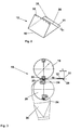
- FIG. 1 can be seen how one or more in a non-illustrated web-fed rotary printing machine printed substrate webs are guided over formers 5 and provided with Leksfalzen. The resulting longitudinally folded printing material webs are then combined to form a total strand 13, from which individual benefits are separated in a cutting device 11.
- the cutting device 11 is formed by a cutting cylinder 9, which preferably carries at its periphery two cutting blades and cooperates with counter cutting strips, which are arranged on the folding blade 14.
- the separated benefits are held by holding devices, such as point needles, on the lateral surface of the folding blade 14 and further conveyed in the direction of the arrow.
- the jaw cylinder 15 promotes the Quergefalzten printed products that are held in the jaw in the direction of arrow and passes it to a Conveyor 17.
- the conveyor 17 is preferably designed as a ribbon cable.
- the conveyor 17 transports the printed products, preferably newspapers, with their transverse fold directed forward to a further cutting device 18.
- This further cutting device 18 consists of a cutting cylinder 19 and a cutting bar cylinder 20, which act on the trailing edge of the printed product and there a portion of the printed product split off.
- the printing length of the web-fed rotary printing press corresponding section length is shortened on the printed product 12.
- a stapler 8 is preferably arranged in the remaining free area of the lateral surface of the folding blade cylinder 14 namely after the cutting cylinder 9, a stapler 8 is preferably arranged. With this stapler 8, the benefits separated from the total strand 13 can be stapled together. Due to the otherwise unobstructed space in this area of the folding blade 14, the stapler 8 is easily accessible. That means he is easy to build or maintain and maintain.
- a folding apparatus according to the invention can be designed both with and without a stapling apparatus.
- FIG. 3 the further cutting device 18 is illustrated enlarged enlarged.
- the cutting cylinder 19 is provided with two cutter bars 22, which cooperate with a cutter bar 23 of the cutter bar cylinder 20, respectively.
- a portion 31 is separated.
- This section 31 is held by puncturing needles 24, which are preferably arranged on the cutting bar 23, and transported in the indicated direction of rotation of the cutting bar cylinder 20 to the suction device 30.
- the suction device 30 sucks the section 31 off the puncturing needles 24.
- the puncturing needles 24 can be moved back in a controlled manner, thereby stripping the portion 31 of the puncturing needles 24.
- the further cutting device 18 is preferably driven by a drive independent of the folding unit 10, which can be controlled so that the cutting device 18 can be operated at different speeds during one revolution, while operating at about the speed of movement of the printed product / useful 12 during the cutting process becomes. Thereby, the length L of the section 31 can be changed.
- the transverse fold 16 is preferably arranged asymmetrically and the portion 31 to be separated is placed in the longer leg. That is, the printed image with the shorter section length compared to the length prescribed by the printing cylinder must be arranged on the printing plate accordingly.
- FIG. 3 As can be seen, the printed product 12 on an asymmetrical transverse fold 16, so that only the lower half of the paper layers must be separated.
- the illustrated printed product 12 is located in FIG. 3 on its title page which is obviously longer than the shorter pages behind it. In this case, one usually speaks of a so-called pre-fold. In the opposite case - that is, if the pages behind are longer - one speaks of a Nachfalz.
- the printed product 12 is shown schematically. At one edge, the puncture stitches 32 of the holding devices of the folding blade cylinder 14 can be seen, and at the other edge, the cutting line 35 can be seen, through which the printed product 12 has been separated from the total strand 13 by the cutting device 11. Furthermore, the cutting line 36 is shown, through which the further cutting device 18 shortens the format length / section length of the printed product.
- the printed product 12 may in its simplest variant in transverse folded form comprise four paper layers. The circumference of the paper layers increases according to the number of paper layers which are fed via the former 5 (FIG. FIG. 1 be folded along.
- the section 31 is preferably disposed of as waste. However, it is also conceivable to print the section 31 and to use it as a benefit.
Landscapes
- Engineering & Computer Science (AREA)
- Mechanical Engineering (AREA)
- Folding Of Thin Sheet-Like Materials, Special Discharging Devices, And Others (AREA)
Abstract
Description
- Die Erfindung betrifft ein Falzwerk und ein Verfahren zum Herstellen eines Druckprodukts gemäß den Merkmalen der Patentansprüche 1 und 9.
- Bei Rotationsdruckmaschinen ist die Länge der herstellbaren Nutzen durch den Umfang der Druckwerkszylinder festgelegt. Solche Anlagen sind auf die Herstellung von Druckprodukten eingeschränkt, deren Format entweder die gesamte Umfangslänge der Druckzylinder ausfüllen oder die zwei- oder mehrfach auf einer zugehörigen Druckplatte hintereinander angeordnet werden können. Druckprodukte mit Formaten ― insbesondere mit Abschnittslängen bei Rollenrotationsdruckmaschinen ― die nur geringfügig kürzer sind, also keinem ganzzahligen Vielfachem der Druckplattenlänge entsprechen, können nicht hergestellt werden.
- Beim Illustrations- bzw. beim Akzidenzdruck ist es allgemein bekannt, insbesondere an hochwertigeren Druckprodukten nach dem Bedrucken und Falzen einen Randbereich abzuschneiden, um etwaige Spuren von Halteeinrichtungen, wie Einstiche von Punkturnadeln oder Abdrücke von Greifern, oder auch Druckkontrollstreifen, die zur Überprüfung der Druckqualität erforderlich waren, zu beseitigen.
- Hierzu sind an Falzwerken von Illustrationsdruckmaschinen im Produktionsfluss nach dem Falzen Schneideinrichtungen angeordnet, welche die gefalzten Produkte mit einer Messer/Gegenmesser-Anordnung beschneiden. Solche Schneideinrichtungen für sogenannte Scherenschnitte führen saubere Schnitte durch, wie sie insbesondere bei hochwertigen Druckprodukten erforderlich sind.
- Es ist jedoch sehr aufwendig entsprechende Schneideinrichtungen bezüglich des Zusammenwirkens der Schneiden aufeinander einzustellen und solche Schneideinrichtungen können nur eine begrenzte Anzahl von Lagen zertrennen.
- Die Aufgabe der Erfindung ist es, ein Falzwerk zu schaffen, mit welchem eine erste Abschnittslänge von Druckprodukten verkürzt werden kann.
- Diese Aufgabe wird erfindungsgemäß durch die Merkmale der Patentansprüche 1 und 9 gelöst.
- Durch ein erfindungsgemäßes Falzwerk ist es vorteilhaft möglich, die durch den Zylinderumfang einer Druckmaschine unveränderlich festgelegte Abschnittslänge eines Druckprodukts zu verkürzen, d.h. Druckprodukte mit einer kürzeren als der vorgegebenen Abschnittslänge herzustellen, wobei diese Abschnittslänge kein ganzzahliges Vielfaches des Druckzylinderumfangs bzw. der zugehörigen Druckplatte betragen muss.
- Durch die erfindungsgemäße Ausführung der weiteren Schneideinrichtung ist es vorteilhaft möglich, eine größere Anzahl von Papierlagen abzuschneiden.
- Weiterhin ist es bei einem erfindungsgemäßen Falzapparat vorteilhaft möglich, im freibleibenden Bereich der Mantelfläche des Falzmesserzylinders, einen Heftapparat anzuordnen, der besonders vorteilhaft leicht zugänglich ist.
- Weitere Merkmale und Vorteile ergeben sich aus den Unteransprüchen in Verbindung mit der Beschreibung.
- Die Erfindung wird nachfolgend anhand der zugehörigen schematischen Zeichnungen näher erläutert. Die
- Fig. 1
- zeigt ein erfindungsgemäßes Falzwerk,
- Fig. 2
- stellt ein mit dem erfindungsgemäßen Falzwerk herstellbares Druckprodukt dar und
- Fig. 3
- ist eine vergrößerte Darstellung der weiteren Schneideinrichtung 18 aus
Fig. 1 . - In
Figur 1 ist ersichtlich wie eine oder mehrere in einer nicht dargestellten Rollenrotationsdruckmaschine bedruckte Bedruckstoffbahnen über Falztrichter 5 geführt und mit Längsfalzen versehen werden. Die dadurch entstandenen längsgefalzten Bedruckstoffbahnen werden danach zu einem Gesamtstrang 13 zusammengeführt, von dem in einer Schneideinrichtung 11 einzelne Nutzen abgetrennt werden. - Die Schneideinrichtung 11 wird von einem Schneidzylinder 9 gebildet, der an seinem Umfang vorzugsweise zwei Schneidmesser trägt und mit Gegenschneidleisten zusammenwirkt, die am Falzmesserzylinder 14 angeordnet sind.
- Die abgetrennten Nutzen werden durch Halteeinrichtungen, wie beispielsweise Punkturnadeln, an der Mantelfläche des Falzmesserzylinders 14 gehalten und in Pfeilrichtung weitergefördert. Sobald sich die Nutzen oder Druckprodukte im Bereich eines Falzklappenzylinders 15 befinden erhalten sie einen Querfalz, indem ein Falzmesser des Falzmesserzylinders 14 ausfährt und die Druckprodukte in eine Falzklappe des Falzklappenzylinders 15 einschiebt.
- Der Falzklappenzylinder 15 fördert die quergefalzten Druckprodukte, die in der Falzklappe festgehalten werden, in Pfeilrichtung weiter und übergibt sie an eine Fördereinrichtung 17. Die Fördereinrichtung 17 ist vorzugsweise als Bandleitung ausgeführt.
- Die Fördereinrichtung 17 transportiert die Druckprodukte, vorzugsweise Zeitungen, mit ihrem Querfalz nach vorn gerichtet zu einer weiteren Schneideinrichtung 18. Diese weitere Schneideinrichtung 18 besteht aus einem Schneidzylinder 19 und einem Schneidleistenzylinder 20, die auf die nacheilende Kante des Druckprodukts wirken und dort einen Abschnitt vom Druckprodukt abtrennen. Damit wird die der Drucklänge der Rollenrotationsdruckmaschine entsprechende Abschnittslänge am Druckprodukt 12 verkürzt.
- Im freibleibenden Bereich der Mantelfläche des Falzmesserzylinders 14 nämlich nach dem Schneidzylinder 9 ist vorzugsweise ein Heftapparat 8 angeordnet. Mit diesem Heftapparat 8 können die vom Gesamtstrang 13 abgetrennten Nutzen zusammengeheftet werden. Aufgrund des ansonsten unverbauten Bauraumes in diesem Bereich des Falzmesserzylinders 14, ist der Heftapparat 8 leicht zugänglich. Das heißt er ist einfach ein- oder aus zu bauen und gewartet werden.
- Ein erfindungsgemäßer Falzapparat kann sowohl mit, als auch ohne Heftapparat ausgeführt sein.
- In
Figur 3 ist die weitere Schneideinrichtung 18 vergrößert schematisch abgebildet. Der Schneidzylinder 19 ist mit zwei Messerbalken 22 versehen, die jeweils mit einer Schneidleiste 23 des Schneidleistenzylinders 20 zusammenwirken. Die vom Gesamtstrang 13 (Fig. 1 ) abgetrennten Druckprodukte 12 werden - mit ihrem Querfalz 16 voraus― zwischen dem Schneidzylinder 19 und dem Schneidleistenzylinder 20 hindurchgeführt, wobei ein Abschnitt 31 abgetrennt wird. Dieser Abschnitt 31 wird von Punkturnadeln 24, die vorzugsweise an der Schneidleiste 23 angeordnet sind, gehalten und in der eingezeichneten Drehrichtung des Schneidleistenzylinders 20 zur Absaugeinrichtung 30 transportiert. Die Absaugeinrichtung 30 saugt den Abschnitt 31 von den Punkturnadeln 24 ab. Damit sich der Abschnitt 31 leichter von den Punkturnadeln 24 ablöst, können die Punkturnadeln 24 gesteuert zurückbewegt werden, wodurch der Abschnitt 31 von den Punkturnadeln 24 abgestreift wird. - Die weitere Schneideinrichtung 18 wird vorzugsweise von einem vom Falzwerk 10 unabhängigen Antrieb angetrieben, der so gesteuert werden kann, dass die Schneideinrichtung 18 während einer Umdrehung mit unterschiedlichen Geschwindigkeiten betrieben werden kann, wobei sie während des Scheidvorganges etwa mit der Bewegungsgeschwindigkeit des Druckprodukts/Nutzens 12 betrieben wird. Dadurch kann die Länge L des Abschnitts 31 verändert werden.
- Damit vorteilhafterweise nur die Hälfte der Papierlagen von der weiteren Schneideinrichtung 18 abgeschnitten werden müssen, wird der Querfalz 16 vorzugsweise asymmetrisch angeordnet und der abzutrennende Abschnitt 31 wird in den längeren Schenkel gelegt. Das heißt das Druckbild mit der kürzeren Abschnittslänge gegenüber der vom Druckzylinder vorgegebenen Länge muss auf der Druckplatte entsprechend angeordnet werden.
- Wie aus
Figur 3 hervorgeht weist das Druckprodukt 12 einen asymmetrischen Querfalz 16 auf, so dass nur die untere Hälfte der Papierlagen abgetrennt werden müssen. Das dargestellte Druckprodukt 12 liegt inFigur 3 auf seiner Titelseite die ersichtlich länger ist als die dahinterliegenden kürzeren Seiten. In diesem Fall wird üblicherweise von einem sogenannten Vorfalz gesprochen. Im umgekehrten Fall ― also wenn die dahinter liegenden Seiten länger sind ― spricht man von einem Nachfalz. - Um mit dem Falzwerk 10 einen asymmetrischen Querfalz zu erzeugen, muss lediglich - in allgemein bekannter Weise - der Abstand der Falzmesser relativ zu den Halteeinrichtungen, d.h. der Kante des Druckprodukts verstellt werden.
- Im beschriebenen Beispiel gemäß
Figur 3 soll auch nach Abtrennen des Abschnitts 31 ein kleiner Überstand ― ein Vorfalz 28 ― am verkürzten Druckprodukt verbleiben. - In
Figur 2 ist das Druckprodukt 12 schematisch dargestellt. An der einen Kante sind die Punkturstiche 32 der Halteeinrichtungen des Falzmesserzylinders 14 ersichtlich und an der anderen Kante ist die Schnittlinie 35 erkennbar, durch welche das Druckprodukt 12 durch die Schneideinrichtung 11 vom Gesamtstrang 13 abgetrennt wurde. Weiterhin ist die Schnittlinie 36 eingezeichnet, durch welche die weitere Schneideinrichtung 18 die Formatlänge / Abschnittslänge des Druckprodukts verkürzt. Das Druckprodukt 12 kann in seiner einfachsten Variante in quergefalzter Form vier Papierlagen umfassen. Der Umfang der Papierlagen nimmt entsprechend der Anzahl der Papierlagen, die über die Falztrichter 5 (Figur 1 längsgefalzt werden zu. - Der Abschnitt 31 wird vorzugsweise als Abfall entsorgt. Es ist jedoch auch denkbar, den Abschnitt 31 zu bedrucken und als Nutzen zu verwerten.
-
- 5
- Falztrichter
- 8
- Heftapparat
- 9
- Schneidzylinder
- 10
- Falzwerk
- 11
- Schneideinrichtung
- 12
- Nutzen/Druckprodukt
- 13
- Gesamtstrang
- 14
- Falzmesserzylinder
- 15
- Falzklappenzylinder
- 16
- Querfalz
- 17
- Fördereinrichtung
- 18
- Schneideinrichtung
- 19
- Schneidzylinder
- 20
- Schneidleistenzylinder
- 21
- Fördereinrichtung
- 22
- Messerbalken
- 23
- Schneidleiste
- 24
- Punkturnadel
- 25
- Schaufelrad
- 26
- Schaufelrad
- 27
- Auslage
- 28
- Vorfalz
- 30
- Absaugeinrichtung
- 31
- Abschnitt
- 32
- Punkturstich
- 35
- Schnittlinie
- 36
- Schnittlinie
- L
- Länge des Abschnitts 31
Claims (6)
- Falzwerk (10) mit einer Scheideinrichtung (11) zum Abtrennen einzelner Nutzen (12) von einer Bedruckstoffbahn (13), mit einem Falzmesserzylinder (14) und einem Falzklappenzylinder (15), zur Anbringung eines Querfalzes an einem Nutzen (12), mit einer Fördereinrichtung (17) zum Transport von quergefalzten Nutzen (12) zu einer weiteren Schneideinrichtung (18), dadurch gekennzeichnet, dass die weitere Schneideinrichtung (18) aus einem Schneidzylinder (19) mit mindestens einem Messerbalken (22) und einem Schneidleistenzylinder (20) mit mindestens einer Schneidleiste (23) besteht.
- Falzwerk nach Anspruch 1, dadurch gekennzeichnet, dass die weitere Schneideinrichtung (18) einen vom Falzwerk (10) unabhängigen eigenen Antrieb aufweist.
- Falzwerk nach Anspruch 2, dadurch gekennzeichnet, dass die weitere Schneideinrichtung (18) während einer Umdrehung mit unterschiedlichen Umfangsgeschwindigkeiten betreibbar ist, wobei sie während eines Schneidvorgangs etwa mit der Bewegungsgeschwindigkeit des Nutzens (12) betreibbar ist.
- Falzwerk nach einem der vorangehenden Ansprüche, dadurch gekennzeichnet, dass an der weiteren Schneideinrichtung eine Absaugvorrichtung zur Abführung von Abschnitten angeordnet ist.
- Falzwerk nach einem der vorangehenden Ansprüche, dadurch gekennzeichnet, dass der Falzmesserzylinder (14) und der Falzklappenzylinder (15) so einstellbar sind, dass der Querfalz (16) am Nutzen (12) asymmetrisch anbringbar ist, wodurch ein Vorfalz oder ein Nachfalz entsteht und durch die weitere Schneideinrichtung (18) der Vorfalz bzw. der Nachfalz abschneidbar ist.
- Verfahren zum Herstellen eines Druckprodukts (12), insbesondere einer Zeitung, wobei eine Bedruckstoffbahn (13) in einer Rollenrotationsdruckmaschine zunächst bedruckt, dann durch eine Längsfalzeinrichtung (5) längsgefalzt wird und danach mit einer Schneideinrichtung (11) eines Falzwerks (10) einzelne Nutzen/Druckprodukte (12) von der längsgefalzten Bedruckstoffbahn (13) abgetrennt sowie quergefalzt werden und danach zu einer weiteren Schneideinrichtung (18) gefördert werden, wo ein weiterer Beschnitt der Druckprodukte (12) erfolgt, um die Abschnittslänge der Druckprodukte (12) zu verkürzen.
Applications Claiming Priority (1)
| Application Number | Priority Date | Filing Date | Title |
|---|---|---|---|
| DE102010005378A DE102010005378A1 (de) | 2010-01-22 | 2010-01-22 | Falzwerk |
Publications (2)
| Publication Number | Publication Date |
|---|---|
| EP2347899A1 true EP2347899A1 (de) | 2011-07-27 |
| EP2347899B1 EP2347899B1 (de) | 2018-04-18 |
Family
ID=43898560
Family Applications (1)
| Application Number | Title | Priority Date | Filing Date |
|---|---|---|---|
| EP11000340.7A Not-in-force EP2347899B1 (de) | 2010-01-22 | 2011-01-18 | Falzwerk |
Country Status (2)
| Country | Link |
|---|---|
| EP (1) | EP2347899B1 (de) |
| DE (1) | DE102010005378A1 (de) |
Cited By (1)
| Publication number | Priority date | Publication date | Assignee | Title |
|---|---|---|---|---|
| CN106626728A (zh) * | 2016-12-21 | 2017-05-10 | 安徽庆丰余防伪科技有限公司 | 一种自动剪裁切边印刷装置 |
Families Citing this family (1)
| Publication number | Priority date | Publication date | Assignee | Title |
|---|---|---|---|---|
| DE102019133111A1 (de) * | 2019-12-05 | 2021-06-10 | Manroland Goss Web Systems Gmbh | Rollendruckmaschine mit Querschneideinrichtung |
Citations (5)
| Publication number | Priority date | Publication date | Assignee | Title |
|---|---|---|---|---|
| EP0302489A2 (de) * | 1987-08-07 | 1989-02-08 | Albert-Frankenthal AG | Falzapparat |
| EP1688381A1 (de) * | 2005-01-20 | 2006-08-09 | MAN Roland Druckmaschinen AG | Falzapparat für eine Rollenrotationsdruckmaschine |
| DE102006057469A1 (de) * | 2006-08-11 | 2008-02-14 | Koenig & Bauer Aktiengesellschaft | Falzapparat und eine Druckanlage |
| DE102007025797A1 (de) * | 2007-06-02 | 2008-12-04 | Koenig & Bauer Aktiengesellschaft | Falzapparat |
| WO2010061695A1 (ja) * | 2008-11-27 | 2010-06-03 | 三菱重工業株式会社 | 折機、印刷機、印刷方法、新聞の作成方法 |
Family Cites Families (6)
| Publication number | Priority date | Publication date | Assignee | Title |
|---|---|---|---|---|
| DE1611283C2 (de) * | 1967-08-09 | 1975-11-27 | Koenig & Bauer Ag, 8700 Wuerzburg | Schneid- und Falzapparat an Rollenrotationsmaschinen |
| DE3030705A1 (de) * | 1980-08-14 | 1982-02-18 | Albert-Frankenthal Ag, 6710 Frankenthal | Vorrichtung zur herstellung von zumindest einmal quergefalzten, parallel zum querfalz beschnittenen produkten |
| DE3030775C2 (de) * | 1980-08-14 | 1993-04-15 | Albert-Frankenthal Ag, 6710 Frankenthal | Falzapparat |
| DE3124639C2 (de) * | 1981-06-23 | 1985-01-17 | Albert-Frankenthal Ag, 6710 Frankenthal | Vorrichtung zum Ausheben von Falzprodukten aus einem Falzklappenzylinder |
| DE4327466A1 (de) * | 1993-08-16 | 1995-02-23 | Roland Man Druckmasch | Vorrichtung zum Querperforieren |
| DE102008045352B4 (de) * | 2008-09-02 | 2011-07-14 | Prinovis Ltd. & Co. KG, 90471 | Verfahren zur Herstellung eines Druckproduktes |
-
2010
- 2010-01-22 DE DE102010005378A patent/DE102010005378A1/de not_active Withdrawn
-
2011
- 2011-01-18 EP EP11000340.7A patent/EP2347899B1/de not_active Not-in-force
Patent Citations (5)
| Publication number | Priority date | Publication date | Assignee | Title |
|---|---|---|---|---|
| EP0302489A2 (de) * | 1987-08-07 | 1989-02-08 | Albert-Frankenthal AG | Falzapparat |
| EP1688381A1 (de) * | 2005-01-20 | 2006-08-09 | MAN Roland Druckmaschinen AG | Falzapparat für eine Rollenrotationsdruckmaschine |
| DE102006057469A1 (de) * | 2006-08-11 | 2008-02-14 | Koenig & Bauer Aktiengesellschaft | Falzapparat und eine Druckanlage |
| DE102007025797A1 (de) * | 2007-06-02 | 2008-12-04 | Koenig & Bauer Aktiengesellschaft | Falzapparat |
| WO2010061695A1 (ja) * | 2008-11-27 | 2010-06-03 | 三菱重工業株式会社 | 折機、印刷機、印刷方法、新聞の作成方法 |
Cited By (1)
| Publication number | Priority date | Publication date | Assignee | Title |
|---|---|---|---|---|
| CN106626728A (zh) * | 2016-12-21 | 2017-05-10 | 安徽庆丰余防伪科技有限公司 | 一种自动剪裁切边印刷装置 |
Also Published As
| Publication number | Publication date |
|---|---|
| EP2347899B1 (de) | 2018-04-18 |
| DE102010005378A1 (de) | 2011-07-28 |
Similar Documents
| Publication | Publication Date | Title |
|---|---|---|
| EP1005984B1 (de) | Verfahren zur Herstellung gefalteter, gebundener Druckerzeugnisse sowie Druckerzeugnis | |
| EP0243720B1 (de) | Falzapparat mit einem zweiten und dritten Falz | |
| EP3603948B1 (de) | Anlage zur herstellung von wellpappe | |
| EP1733988A1 (de) | Verfahren und Vorrichtung zur Herstellung von Zeitungen | |
| EP2177465B1 (de) | Falzapparat und Falzverfahren | |
| DE2517000A1 (de) | Falzapparat fuer quergefalzte und/ oder laengsgefalzte produkte fuer buecher und umschlaege | |
| EP2484617A1 (de) | Falzmaschine mit einer Einrichtung zum Falzkantenbeschnitt und Verfahren zum Falzen von Bogen | |
| EP1922276B1 (de) | Falzapparat | |
| CH705699B1 (de) | Einrichtung und Verfahren zum Falzen und Querschneiden einer Bedruckstoffbahn. | |
| EP1896266B1 (de) | Rollenrotationsdruckmaschine mit formzylinderbelegung | |
| EP2347899B1 (de) | Falzwerk | |
| EP2336062B1 (de) | Verfahren und Vorrichtung zur Verarbeitung von aus mehreren Papierlagen bestehenden Druckprodukten. | |
| DE3121992A1 (de) | "mit werbung bedruckte bogenbahn, verfahren zur herstellung eines gedruckten werbemittels aus der bedruckten bogenbahn sowie vorrichtung zur durchfuehrung des verfahrens" | |
| DE102014205938B4 (de) | Verfahren zur Herstellung eines Druckproduktes in einer Druckmaschine | |
| DE102012201099B4 (de) | Vorrichtung und Verfahren zur Herstellung eines Druckproduktes | |
| DE3305760C2 (de) | ||
| DE102014222387B4 (de) | Verfahren zur Herstellung eines Druckproduktes sowie Druckprodukt | |
| EP2411230B1 (de) | Als zeitung ausgebildetes druckprodukt | |
| DE102004005807B4 (de) | Falzapparat | |
| DE102014207835B4 (de) | Verfahren und Druckmaschine zur Herstellung von Druckprodukten | |
| DE102016216429B4 (de) | Druckprodukt, Verfahren und Rollendruckmaschine zur Herstellung eines Druckproduktes | |
| DE102024103317A1 (de) | Faltschachtelklebemaschine mit integriertem Messerwellenmodul | |
| EP1954497A1 (de) | Verfahren und einrichtung zur herstellung von druckprodukten | |
| DE102007025797A1 (de) | Falzapparat | |
| DE8116439U1 (de) | Vorrichtung zur Herstellung eines gdruckten, personalisierten Werbemittels |
Legal Events
| Date | Code | Title | Description |
|---|---|---|---|
| PUAI | Public reference made under article 153(3) epc to a published international application that has entered the european phase |
Free format text: ORIGINAL CODE: 0009012 |
|
| AK | Designated contracting states |
Kind code of ref document: A1 Designated state(s): AL AT BE BG CH CY CZ DE DK EE ES FI FR GB GR HR HU IE IS IT LI LT LU LV MC MK MT NL NO PL PT RO RS SE SI SK SM TR |
|
| AX | Request for extension of the european patent |
Extension state: BA ME |
|
| 19U | Interruption of proceedings before grant |
Effective date: 20120201 |
|
| 19W | Proceedings resumed before grant after interruption of proceedings |
Effective date: 20131001 |
|
| 17P | Request for examination filed |
Effective date: 20120127 |
|
| RAP1 | Party data changed (applicant data changed or rights of an application transferred) |
Owner name: MANROLAND WEB SYSTEMS GMBH |
|
| RBV | Designated contracting states (corrected) |
Designated state(s): AL AT BE BG CH CY CZ DE DK EE ES FI FR GB GR HR HU IE IS IT LI LT LU LV MC MK MT NL NO PL PT RO RS SE SI SK SM TR |
|
| STAA | Information on the status of an ep patent application or granted ep patent |
Free format text: STATUS: EXAMINATION IS IN PROGRESS |
|
| 17Q | First examination report despatched |
Effective date: 20170811 |
|
| GRAP | Despatch of communication of intention to grant a patent |
Free format text: ORIGINAL CODE: EPIDOSNIGR1 |
|
| STAA | Information on the status of an ep patent application or granted ep patent |
Free format text: STATUS: GRANT OF PATENT IS INTENDED |
|
| INTG | Intention to grant announced |
Effective date: 20180109 |
|
| GRAS | Grant fee paid |
Free format text: ORIGINAL CODE: EPIDOSNIGR3 |
|
| GRAA | (expected) grant |
Free format text: ORIGINAL CODE: 0009210 |
|
| STAA | Information on the status of an ep patent application or granted ep patent |
Free format text: STATUS: THE PATENT HAS BEEN GRANTED |
|
| AK | Designated contracting states |
Kind code of ref document: B1 Designated state(s): AL AT BE BG CH CY CZ DE DK EE ES FI FR GB GR HR HU IE IS IT LI LT LU LV MC MK MT NL NO PL PT RO RS SE SI SK SM TR |
|
| REG | Reference to a national code |
Ref country code: GB Ref legal event code: FG4D Free format text: NOT ENGLISH |
|
| REG | Reference to a national code |
Ref country code: CH Ref legal event code: EP |
|
| REG | Reference to a national code |
Ref country code: AT Ref legal event code: REF Ref document number: 989988 Country of ref document: AT Kind code of ref document: T Effective date: 20180515 |
|
| REG | Reference to a national code |
Ref country code: IE Ref legal event code: FG4D Free format text: LANGUAGE OF EP DOCUMENT: GERMAN |
|
| REG | Reference to a national code |
Ref country code: DE Ref legal event code: R096 Ref document number: 502011014045 Country of ref document: DE |
|
| REG | Reference to a national code |
Ref country code: NL Ref legal event code: MP Effective date: 20180418 |
|
| REG | Reference to a national code |
Ref country code: LT Ref legal event code: MG4D |
|
| PG25 | Lapsed in a contracting state [announced via postgrant information from national office to epo] |
Ref country code: NL Free format text: LAPSE BECAUSE OF FAILURE TO SUBMIT A TRANSLATION OF THE DESCRIPTION OR TO PAY THE FEE WITHIN THE PRESCRIBED TIME-LIMIT Effective date: 20180418 |
|
| RAP2 | Party data changed (patent owner data changed or rights of a patent transferred) |
Owner name: MANROLAND GOSS WEB SYSTEMS GMBH |
|
| PG25 | Lapsed in a contracting state [announced via postgrant information from national office to epo] |
Ref country code: BG Free format text: LAPSE BECAUSE OF FAILURE TO SUBMIT A TRANSLATION OF THE DESCRIPTION OR TO PAY THE FEE WITHIN THE PRESCRIBED TIME-LIMIT Effective date: 20180718 Ref country code: FI Free format text: LAPSE BECAUSE OF FAILURE TO SUBMIT A TRANSLATION OF THE DESCRIPTION OR TO PAY THE FEE WITHIN THE PRESCRIBED TIME-LIMIT Effective date: 20180418 Ref country code: SE Free format text: LAPSE BECAUSE OF FAILURE TO SUBMIT A TRANSLATION OF THE DESCRIPTION OR TO PAY THE FEE WITHIN THE PRESCRIBED TIME-LIMIT Effective date: 20180418 Ref country code: ES Free format text: LAPSE BECAUSE OF FAILURE TO SUBMIT A TRANSLATION OF THE DESCRIPTION OR TO PAY THE FEE WITHIN THE PRESCRIBED TIME-LIMIT Effective date: 20180418 Ref country code: AL Free format text: LAPSE BECAUSE OF FAILURE TO SUBMIT A TRANSLATION OF THE DESCRIPTION OR TO PAY THE FEE WITHIN THE PRESCRIBED TIME-LIMIT Effective date: 20180418 Ref country code: LT Free format text: LAPSE BECAUSE OF FAILURE TO SUBMIT A TRANSLATION OF THE DESCRIPTION OR TO PAY THE FEE WITHIN THE PRESCRIBED TIME-LIMIT Effective date: 20180418 Ref country code: PL Free format text: LAPSE BECAUSE OF FAILURE TO SUBMIT A TRANSLATION OF THE DESCRIPTION OR TO PAY THE FEE WITHIN THE PRESCRIBED TIME-LIMIT Effective date: 20180418 Ref country code: NO Free format text: LAPSE BECAUSE OF FAILURE TO SUBMIT A TRANSLATION OF THE DESCRIPTION OR TO PAY THE FEE WITHIN THE PRESCRIBED TIME-LIMIT Effective date: 20180718 |
|
| REG | Reference to a national code |
Ref country code: DE Ref legal event code: R081 Ref document number: 502011014045 Country of ref document: DE Owner name: MANROLAND GOSS WEB SYSTEMS GMBH, DE Free format text: FORMER OWNER: MANROLAND WEB SYSTEMS GMBH, 86153 AUGSBURG, DE |
|
| PG25 | Lapsed in a contracting state [announced via postgrant information from national office to epo] |
Ref country code: LV Free format text: LAPSE BECAUSE OF FAILURE TO SUBMIT A TRANSLATION OF THE DESCRIPTION OR TO PAY THE FEE WITHIN THE PRESCRIBED TIME-LIMIT Effective date: 20180418 Ref country code: RS Free format text: LAPSE BECAUSE OF FAILURE TO SUBMIT A TRANSLATION OF THE DESCRIPTION OR TO PAY THE FEE WITHIN THE PRESCRIBED TIME-LIMIT Effective date: 20180418 Ref country code: HR Free format text: LAPSE BECAUSE OF FAILURE TO SUBMIT A TRANSLATION OF THE DESCRIPTION OR TO PAY THE FEE WITHIN THE PRESCRIBED TIME-LIMIT Effective date: 20180418 Ref country code: GR Free format text: LAPSE BECAUSE OF FAILURE TO SUBMIT A TRANSLATION OF THE DESCRIPTION OR TO PAY THE FEE WITHIN THE PRESCRIBED TIME-LIMIT Effective date: 20180719 |
|
| PG25 | Lapsed in a contracting state [announced via postgrant information from national office to epo] |
Ref country code: PT Free format text: LAPSE BECAUSE OF FAILURE TO SUBMIT A TRANSLATION OF THE DESCRIPTION OR TO PAY THE FEE WITHIN THE PRESCRIBED TIME-LIMIT Effective date: 20180820 |
|
| REG | Reference to a national code |
Ref country code: DE Ref legal event code: R097 Ref document number: 502011014045 Country of ref document: DE |
|
| PG25 | Lapsed in a contracting state [announced via postgrant information from national office to epo] |
Ref country code: EE Free format text: LAPSE BECAUSE OF FAILURE TO SUBMIT A TRANSLATION OF THE DESCRIPTION OR TO PAY THE FEE WITHIN THE PRESCRIBED TIME-LIMIT Effective date: 20180418 Ref country code: RO Free format text: LAPSE BECAUSE OF FAILURE TO SUBMIT A TRANSLATION OF THE DESCRIPTION OR TO PAY THE FEE WITHIN THE PRESCRIBED TIME-LIMIT Effective date: 20180418 Ref country code: CZ Free format text: LAPSE BECAUSE OF FAILURE TO SUBMIT A TRANSLATION OF THE DESCRIPTION OR TO PAY THE FEE WITHIN THE PRESCRIBED TIME-LIMIT Effective date: 20180418 Ref country code: SK Free format text: LAPSE BECAUSE OF FAILURE TO SUBMIT A TRANSLATION OF THE DESCRIPTION OR TO PAY THE FEE WITHIN THE PRESCRIBED TIME-LIMIT Effective date: 20180418 Ref country code: DK Free format text: LAPSE BECAUSE OF FAILURE TO SUBMIT A TRANSLATION OF THE DESCRIPTION OR TO PAY THE FEE WITHIN THE PRESCRIBED TIME-LIMIT Effective date: 20180418 |
|
| PLBE | No opposition filed within time limit |
Free format text: ORIGINAL CODE: 0009261 |
|
| STAA | Information on the status of an ep patent application or granted ep patent |
Free format text: STATUS: NO OPPOSITION FILED WITHIN TIME LIMIT |
|
| PG25 | Lapsed in a contracting state [announced via postgrant information from national office to epo] |
Ref country code: SM Free format text: LAPSE BECAUSE OF FAILURE TO SUBMIT A TRANSLATION OF THE DESCRIPTION OR TO PAY THE FEE WITHIN THE PRESCRIBED TIME-LIMIT Effective date: 20180418 Ref country code: IT Free format text: LAPSE BECAUSE OF FAILURE TO SUBMIT A TRANSLATION OF THE DESCRIPTION OR TO PAY THE FEE WITHIN THE PRESCRIBED TIME-LIMIT Effective date: 20180418 |
|
| 26N | No opposition filed |
Effective date: 20190121 |
|
| PGFP | Annual fee paid to national office [announced via postgrant information from national office to epo] |
Ref country code: DE Payment date: 20190123 Year of fee payment: 9 |
|
| PG25 | Lapsed in a contracting state [announced via postgrant information from national office to epo] |
Ref country code: SI Free format text: LAPSE BECAUSE OF FAILURE TO SUBMIT A TRANSLATION OF THE DESCRIPTION OR TO PAY THE FEE WITHIN THE PRESCRIBED TIME-LIMIT Effective date: 20180418 |
|
| PG25 | Lapsed in a contracting state [announced via postgrant information from national office to epo] |
Ref country code: MC Free format text: LAPSE BECAUSE OF FAILURE TO SUBMIT A TRANSLATION OF THE DESCRIPTION OR TO PAY THE FEE WITHIN THE PRESCRIBED TIME-LIMIT Effective date: 20180418 |
|
| REG | Reference to a national code |
Ref country code: CH Ref legal event code: PL |
|
| GBPC | Gb: european patent ceased through non-payment of renewal fee |
Effective date: 20190118 |
|
| PG25 | Lapsed in a contracting state [announced via postgrant information from national office to epo] |
Ref country code: LU Free format text: LAPSE BECAUSE OF NON-PAYMENT OF DUE FEES Effective date: 20190118 |
|
| REG | Reference to a national code |
Ref country code: BE Ref legal event code: MM Effective date: 20190131 |
|
| REG | Reference to a national code |
Ref country code: IE Ref legal event code: MM4A |
|
| PG25 | Lapsed in a contracting state [announced via postgrant information from national office to epo] |
Ref country code: FR Free format text: LAPSE BECAUSE OF NON-PAYMENT OF DUE FEES Effective date: 20190131 |
|
| PG25 | Lapsed in a contracting state [announced via postgrant information from national office to epo] |
Ref country code: BE Free format text: LAPSE BECAUSE OF NON-PAYMENT OF DUE FEES Effective date: 20190131 |
|
| PG25 | Lapsed in a contracting state [announced via postgrant information from national office to epo] |
Ref country code: CH Free format text: LAPSE BECAUSE OF NON-PAYMENT OF DUE FEES Effective date: 20190131 Ref country code: GB Free format text: LAPSE BECAUSE OF NON-PAYMENT OF DUE FEES Effective date: 20190118 Ref country code: LI Free format text: LAPSE BECAUSE OF NON-PAYMENT OF DUE FEES Effective date: 20190131 |
|
| PG25 | Lapsed in a contracting state [announced via postgrant information from national office to epo] |
Ref country code: IE Free format text: LAPSE BECAUSE OF NON-PAYMENT OF DUE FEES Effective date: 20190118 |
|
| REG | Reference to a national code |
Ref country code: AT Ref legal event code: MM01 Ref document number: 989988 Country of ref document: AT Kind code of ref document: T Effective date: 20190118 |
|
| PG25 | Lapsed in a contracting state [announced via postgrant information from national office to epo] |
Ref country code: TR Free format text: LAPSE BECAUSE OF FAILURE TO SUBMIT A TRANSLATION OF THE DESCRIPTION OR TO PAY THE FEE WITHIN THE PRESCRIBED TIME-LIMIT Effective date: 20180418 |
|
| PG25 | Lapsed in a contracting state [announced via postgrant information from national office to epo] |
Ref country code: AT Free format text: LAPSE BECAUSE OF NON-PAYMENT OF DUE FEES Effective date: 20190118 |
|
| PG25 | Lapsed in a contracting state [announced via postgrant information from national office to epo] |
Ref country code: MT Free format text: LAPSE BECAUSE OF FAILURE TO SUBMIT A TRANSLATION OF THE DESCRIPTION OR TO PAY THE FEE WITHIN THE PRESCRIBED TIME-LIMIT Effective date: 20180418 |
|
| REG | Reference to a national code |
Ref country code: DE Ref legal event code: R119 Ref document number: 502011014045 Country of ref document: DE |
|
| PG25 | Lapsed in a contracting state [announced via postgrant information from national office to epo] |
Ref country code: DE Free format text: LAPSE BECAUSE OF NON-PAYMENT OF DUE FEES Effective date: 20200801 |
|
| PG25 | Lapsed in a contracting state [announced via postgrant information from national office to epo] |
Ref country code: CY Free format text: LAPSE BECAUSE OF FAILURE TO SUBMIT A TRANSLATION OF THE DESCRIPTION OR TO PAY THE FEE WITHIN THE PRESCRIBED TIME-LIMIT Effective date: 20180418 |
|
| PG25 | Lapsed in a contracting state [announced via postgrant information from national office to epo] |
Ref country code: IS Free format text: LAPSE BECAUSE OF FAILURE TO SUBMIT A TRANSLATION OF THE DESCRIPTION OR TO PAY THE FEE WITHIN THE PRESCRIBED TIME-LIMIT Effective date: 20180818 |
|
| PG25 | Lapsed in a contracting state [announced via postgrant information from national office to epo] |
Ref country code: HU Free format text: LAPSE BECAUSE OF FAILURE TO SUBMIT A TRANSLATION OF THE DESCRIPTION OR TO PAY THE FEE WITHIN THE PRESCRIBED TIME-LIMIT; INVALID AB INITIO Effective date: 20110118 |
|
| PG25 | Lapsed in a contracting state [announced via postgrant information from national office to epo] |
Ref country code: MK Free format text: LAPSE BECAUSE OF FAILURE TO SUBMIT A TRANSLATION OF THE DESCRIPTION OR TO PAY THE FEE WITHIN THE PRESCRIBED TIME-LIMIT Effective date: 20180418 |