EP2347076B1 - Stellantrieb für bewegbare möbelteile - Google Patents
Stellantrieb für bewegbare möbelteile Download PDFInfo
- Publication number
- EP2347076B1 EP2347076B1 EP09775626.6A EP09775626A EP2347076B1 EP 2347076 B1 EP2347076 B1 EP 2347076B1 EP 09775626 A EP09775626 A EP 09775626A EP 2347076 B1 EP2347076 B1 EP 2347076B1
- Authority
- EP
- European Patent Office
- Prior art keywords
- key
- actuating drive
- actuating
- actuator
- drive according
- Prior art date
- Legal status (The legal status is an assumption and is not a legal conclusion. Google has not performed a legal analysis and makes no representation as to the accuracy of the status listed.)
- Active
Links
Images


Classifications
-
- E—FIXED CONSTRUCTIONS
- E05—LOCKS; KEYS; WINDOW OR DOOR FITTINGS; SAFES
- E05F—DEVICES FOR MOVING WINGS INTO OPEN OR CLOSED POSITION; CHECKS FOR WINGS; WING FITTINGS NOT OTHERWISE PROVIDED FOR, CONCERNED WITH THE FUNCTIONING OF THE WING
- E05F1/00—Closers or openers for wings, not otherwise provided for in this subclass
- E05F1/08—Closers or openers for wings, not otherwise provided for in this subclass spring-actuated, e.g. for horizontally sliding wings
- E05F1/10—Closers or openers for wings, not otherwise provided for in this subclass spring-actuated, e.g. for horizontally sliding wings for swinging wings, e.g. counterbalance
- E05F1/1041—Closers or openers for wings, not otherwise provided for in this subclass spring-actuated, e.g. for horizontally sliding wings for swinging wings, e.g. counterbalance with a coil spring perpendicular to the pivot axis
- E05F1/105—Closers or openers for wings, not otherwise provided for in this subclass spring-actuated, e.g. for horizontally sliding wings for swinging wings, e.g. counterbalance with a coil spring perpendicular to the pivot axis with a compression spring
- E05F1/1058—Closers or openers for wings, not otherwise provided for in this subclass spring-actuated, e.g. for horizontally sliding wings for swinging wings, e.g. counterbalance with a coil spring perpendicular to the pivot axis with a compression spring for counterbalancing
-
- E—FIXED CONSTRUCTIONS
- E05—LOCKS; KEYS; WINDOW OR DOOR FITTINGS; SAFES
- E05D—HINGES OR SUSPENSION DEVICES FOR DOORS, WINDOWS OR WINGS
- E05D15/00—Suspension arrangements for wings
- E05D15/26—Suspension arrangements for wings for folding wings
- E05D15/262—Suspension arrangements for wings for folding wings folding vertically
-
- E—FIXED CONSTRUCTIONS
- E05—LOCKS; KEYS; WINDOW OR DOOR FITTINGS; SAFES
- E05D—HINGES OR SUSPENSION DEVICES FOR DOORS, WINDOWS OR WINGS
- E05D15/00—Suspension arrangements for wings
- E05D15/40—Suspension arrangements for wings supported on arms movable in vertical planes
- E05D15/401—Suspension arrangements for wings supported on arms movable in vertical planes specially adapted for overhead wings
-
- E—FIXED CONSTRUCTIONS
- E05—LOCKS; KEYS; WINDOW OR DOOR FITTINGS; SAFES
- E05Y—INDEXING SCHEME ASSOCIATED WITH SUBCLASSES E05D AND E05F, RELATING TO CONSTRUCTION ELEMENTS, ELECTRIC CONTROL, POWER SUPPLY, POWER SIGNAL OR TRANSMISSION, USER INTERFACES, MOUNTING OR COUPLING, DETAILS, ACCESSORIES, AUXILIARY OPERATIONS NOT OTHERWISE PROVIDED FOR, APPLICATION THEREOF
- E05Y2201/00—Constructional elements; Accessories therefor
- E05Y2201/20—Brakes; Disengaging means; Holders; Stops; Valves; Accessories therefor
- E05Y2201/218—Holders
- E05Y2201/22—Locks
-
- E—FIXED CONSTRUCTIONS
- E05—LOCKS; KEYS; WINDOW OR DOOR FITTINGS; SAFES
- E05Y—INDEXING SCHEME ASSOCIATED WITH SUBCLASSES E05D AND E05F, RELATING TO CONSTRUCTION ELEMENTS, ELECTRIC CONTROL, POWER SUPPLY, POWER SIGNAL OR TRANSMISSION, USER INTERFACES, MOUNTING OR COUPLING, DETAILS, ACCESSORIES, AUXILIARY OPERATIONS NOT OTHERWISE PROVIDED FOR, APPLICATION THEREOF
- E05Y2201/00—Constructional elements; Accessories therefor
- E05Y2201/60—Suspension or transmission members; Accessories therefor
- E05Y2201/622—Suspension or transmission members elements
-
- E—FIXED CONSTRUCTIONS
- E05—LOCKS; KEYS; WINDOW OR DOOR FITTINGS; SAFES
- E05Y—INDEXING SCHEME ASSOCIATED WITH SUBCLASSES E05D AND E05F, RELATING TO CONSTRUCTION ELEMENTS, ELECTRIC CONTROL, POWER SUPPLY, POWER SIGNAL OR TRANSMISSION, USER INTERFACES, MOUNTING OR COUPLING, DETAILS, ACCESSORIES, AUXILIARY OPERATIONS NOT OTHERWISE PROVIDED FOR, APPLICATION THEREOF
- E05Y2800/00—Details, accessories and auxiliary operations not otherwise provided for
- E05Y2800/20—Combinations of elements
- E05Y2800/205—Combinations of elements forming a unit
-
- E—FIXED CONSTRUCTIONS
- E05—LOCKS; KEYS; WINDOW OR DOOR FITTINGS; SAFES
- E05Y—INDEXING SCHEME ASSOCIATED WITH SUBCLASSES E05D AND E05F, RELATING TO CONSTRUCTION ELEMENTS, ELECTRIC CONTROL, POWER SUPPLY, POWER SIGNAL OR TRANSMISSION, USER INTERFACES, MOUNTING OR COUPLING, DETAILS, ACCESSORIES, AUXILIARY OPERATIONS NOT OTHERWISE PROVIDED FOR, APPLICATION THEREOF
- E05Y2800/00—Details, accessories and auxiliary operations not otherwise provided for
- E05Y2800/20—Combinations of elements
- E05Y2800/21—Combinations of elements of identical elements, e.g. of identical compression springs
-
- E—FIXED CONSTRUCTIONS
- E05—LOCKS; KEYS; WINDOW OR DOOR FITTINGS; SAFES
- E05Y—INDEXING SCHEME ASSOCIATED WITH SUBCLASSES E05D AND E05F, RELATING TO CONSTRUCTION ELEMENTS, ELECTRIC CONTROL, POWER SUPPLY, POWER SIGNAL OR TRANSMISSION, USER INTERFACES, MOUNTING OR COUPLING, DETAILS, ACCESSORIES, AUXILIARY OPERATIONS NOT OTHERWISE PROVIDED FOR, APPLICATION THEREOF
- E05Y2800/00—Details, accessories and auxiliary operations not otherwise provided for
- E05Y2800/20—Combinations of elements
- E05Y2800/242—Combinations of elements arranged in parallel relationship
-
- E—FIXED CONSTRUCTIONS
- E05—LOCKS; KEYS; WINDOW OR DOOR FITTINGS; SAFES
- E05Y—INDEXING SCHEME ASSOCIATED WITH SUBCLASSES E05D AND E05F, RELATING TO CONSTRUCTION ELEMENTS, ELECTRIC CONTROL, POWER SUPPLY, POWER SIGNAL OR TRANSMISSION, USER INTERFACES, MOUNTING OR COUPLING, DETAILS, ACCESSORIES, AUXILIARY OPERATIONS NOT OTHERWISE PROVIDED FOR, APPLICATION THEREOF
- E05Y2900/00—Application of doors, windows, wings or fittings thereof
- E05Y2900/20—Application of doors, windows, wings or fittings thereof for furniture, e.g. cabinets
-
- Y—GENERAL TAGGING OF NEW TECHNOLOGICAL DEVELOPMENTS; GENERAL TAGGING OF CROSS-SECTIONAL TECHNOLOGIES SPANNING OVER SEVERAL SECTIONS OF THE IPC; TECHNICAL SUBJECTS COVERED BY FORMER USPC CROSS-REFERENCE ART COLLECTIONS [XRACs] AND DIGESTS
- Y10—TECHNICAL SUBJECTS COVERED BY FORMER USPC
- Y10T—TECHNICAL SUBJECTS COVERED BY FORMER US CLASSIFICATION
- Y10T70/00—Locks
- Y10T70/50—Special application
- Y10T70/5093—For closures
- Y10T70/5155—Door
-
- Y—GENERAL TAGGING OF NEW TECHNOLOGICAL DEVELOPMENTS; GENERAL TAGGING OF CROSS-SECTIONAL TECHNOLOGIES SPANNING OVER SEVERAL SECTIONS OF THE IPC; TECHNICAL SUBJECTS COVERED BY FORMER USPC CROSS-REFERENCE ART COLLECTIONS [XRACs] AND DIGESTS
- Y10—TECHNICAL SUBJECTS COVERED BY FORMER USPC
- Y10T—TECHNICAL SUBJECTS COVERED BY FORMER US CLASSIFICATION
- Y10T70/00—Locks
- Y10T70/50—Special application
- Y10T70/5611—For control and machine elements
- Y10T70/569—Lever
Definitions
- the present invention relates to an actuator with at least one actuator for moving a movable furniture part and with a locking device for inhibiting movement of the actuator.
- the invention relates to a piece of furniture with at least one actuator of the type to be described.
- Such actuators are particularly attached to the furniture body of a piece of furniture, the actuator being provided for moving a flap that can be moved up.
- the object of the present invention is to propose an actuator of the type mentioned at the outset, which allows a controlled movement of the actuator.
- the locking device has a lock arranged in or on the actuator, which can be unlocked by a key to release the movement of the actuator.
- the lock can be both unlocked and - if appropriate - locked.
- the actuator is preassembled in or on the furniture and the movement of the actuator is to be inhibited in the closed position of the movable furniture part, it may be expedient to provide a through opening on the furniture which allows the key to be inserted from a position outside the furniture into the lock located on or in the actuator is permitted.
- the proposed locking device with the lock and the key is used as a mounting lock for the "empty" actuator, so that no movable furniture part - in particular a movable furniture flap - is yet mounted on the actuator.
- These actuators serve to move a furniture flap mounted on the pivotably mounted actuator (in particular on an actuating arm) between a vertical position closing a cabinet compartment in a furniture body and an open position moved upwards.
- a spring device or a gas pressure accumulator is used to compensate for the flap weight, the torque acting on the actuator being selectively adjustable to the weight of the furniture flap to be moved. In the case of heavy furniture flaps, a relatively high torque must therefore be provided as a pretensioning force for the actuating arm.
- the spring device acts on the actuator, which can preferably be pivoted about a horizontal axis, in the opening direction, there is a considerable risk of injury when the valve is not mounted due to an actuator which deflects upwards.
- the locking device with the lock and the key allows the actuator to be locked in its fully open position. The actuator can therefore not be moved due to the locking against the acting force of the spring device. In this way, a problem-free assembly of the flap on the actuator locked in the fully open position is possible.
- the key is secured by a releasable holding device on or in the actuator and that the releasable holding device only releases the key when the flap has been installed on the actuator.
- the key to release the lock is only available if the flap has been properly installed on the actuator. If the flap is securely attached to the actuator, there is also the risk of an upward movement deflecting actuator largely banned. Only after the flap has been installed does the releasable holding device release the key, whereupon the locking device can be unlocked and then the actuator can be moved freely between a closed position and an open position.
- the key unlocks the locking device only as long as the key is inserted in the lock.
- the actuator can only be moved freely with a key inserted in the lock. If the key is removed from the lock, the locking device can automatically block a movement of the actuator.
- the actuator usually has a power train, which in the simplest case comprises the actuator and the spring device acting on the actuator.
- the locking device locks at least one element of this power train, ie the spring device and / or the actuator.
- the power train it is also possible for the power train to have a transmission mechanism (either a lever mechanism and / or a transmission) acting between the spring device and the actuator, wherein at least one element of the transmission mechanism can be locked by the locking device.
- the locking device has at least one locking element, by means of which the element of the power train can be locked relative to a furniture-fixed part - preferably the housing of the actuator. It can be advantageous if the locking element can be moved by the key from a position locking the element of the power train into a release position in which the locking element is unlocked by the element of the power train.
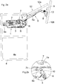
- Fig. 1a shows a side view of an actuator 1 according to the invention with a housing 2, which is preassembled on a side wall 4a of a furniture body 4.
- the actuator 1 has in a known manner a spring device 3, which is supported on the one hand on a furniture-fixed bearing 3a on the housing 2 and on the other hand acts on the actuator 5 in the form of an actuator arm 5a about the axis of rotation R in the opening direction.
- a transmission mechanism in the form of an intermediate lever 6 is arranged, which is pivotably mounted about an axis of rotation S.
- a locking device 7 can be seen which, in the exemplary embodiment shown, locks the intermediate lever 6 and inhibits it from pivoting about the axis of rotation S.
- the actuator 5 in the form of the actuating arm 5a can be locked in its fully open position.
- This locking device 7 is therefore part of a mounting lock for the "empty" actuating arm 5a, to which no furniture flap is hinged.
- By locking the actuating arm 5a in its fully open position it cannot be pressed in the direction of the closed position.
- this has the advantage that a furniture flap can be connected without problems to the locked and thus stably held actuating arm 5a.
- the actuating arm 5a can also not be pressed in the direction of the closed position, since this - in particular out of inattentiveness - slips out of an intermediate position upstream of the fully open position in an uncontrolled manner and, due to the sometimes extremely high pretensioning forces of the spring device 3, returns to the full position Can snap open position and cause massive injuries.
- the actuator 5 in the form of the actuator arm 5a has a fastening device 8 for detachable connection to a (not shown) flap-side fitting part, whereby a furniture flap can be connected to the actuator arm 5a.
- a schematically represented key 9 can be seen, which is secured by a releasable holding device on or in the fastening device 8.
- the key 9 can only be released from the fastening device 8 if a flap is properly connected to the fastening device 8. Only after the flap has been mounted on the actuating arm 5a is the key 9 released and can then be fed to the locking device 7, as a result of which the lock can be released and the actuating arm 5a can be pivoted between the closed position and the open position.
- Fig. 1b shows the in Fig. 1a circled area in an enlarged view.
- the spring device 3 presses against the intermediate lever 6 on a spring bearing 10, the position of the spring bearing 10 being adjustable relative to the intermediate lever 6 by an adjusting device 11.
- the locking device 7 comprises a lock 7a into which the key 9 can be inserted after the flap has been installed (at right angles to the plane of the drawing), as a result of which the locking element 7c of the locking device 7 can be unlocked by the intermediate lever 6. If the locking element 7c is released from the intermediate lever 6, the actuating arm 5a can also be moved freely again.
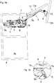
- Fig. 2a shows the arrangement according to Fig. 1a , wherein the fastening device 8 of the variable-length adjusting arm 5a is properly connected to a fitting part 13 assigned to the furniture flap 12. If the correct connection between the fastening device 8 and the flap-side fitting part 13 is thus established, the key 9 is also released, as indicated in the figure. The intermediate lever 6 is still locked in the illustration shown, however, the locking device 7 can be released from the intermediate lever 6 by the key 9 which has now been released.
- the flap 12 is in the embodiment shown as a two-part flap 12 with partial flaps 12a and 12b educated.
- the upper partial flap 12a is pivotally mounted relative to the furniture body 4, the lower partial flap 12b is pivotally mounted relative to the upper partial flap 12a by means of a connection fitting (not shown).
- a connection fitting (not shown).
- the two partial flaps 12a and 12b assume a vertical position and cover the cabinet compartment of the furniture body 4 essentially completely.
- Fig. 2b shows an enlarged view of the in Fig. 2a encircled area with the locking device 7 in the locked position, the locking element 7c being locked with a locking element 6a assigned to the intermediate lever 6.
- FIG. 3a and 3b show the unlocked locking device 7, wherein the in Fig. 2a released key 9 was inserted into the lock 7a of the locking device 7.
- the key 9 By inserting the key 9 into the lock 7a of the locking device 7, as in FIG Fig. 3b shown - the locking element 7c pivoted and released from the locking part 6a of the intermediate lever 6.
- the intermediate lever 6 can now be pivoted about its axis of rotation S, whereby a pivoting movement of the actuating arm 5a is also possible again.
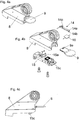
- Fig. 4a shows a perspective view of the fastening device 8, which for releasable connection to the in Fig. 2a and Fig. 3a flap-side fitting part 13 is provided.
- the key 9 can be seen, which can only be released from the fastening device 8 after the flap has been installed.
- Fig. 4b shows an exploded view of the fastening device 8, which has a holding device 14 for the key 9.
- the holding device 14 comprises a movable coupling part 14a with a locking element 14b, which is locked in the locked position with a corresponding locking element 9a of the key 9, so that the key 9 is locked relative to the holding device 14.
- the movable, peg-shaped actuating element 15a is namely pressed during the assembly of the flap 12 in the direction of the arrow Y, as a result of which the coupling part 14a moves about the axis 14c and the locking element 9a of the key 9 is released.
- the holding element 15 comprises a resilient or a spring-loaded support part 15c which can be latched to the flap-side fitting part 13.
- a pivotable securing part 16 can also be seen, which locks the supporting part 15c when the key 9 is removed.
- Fig. 4c shows a side view of the fastening device 8 with secured key 9.
- the key 9 is also secured to the flap-side fitting part 13 via the releasable holding device 14.
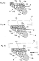
- the 5a-5c each show vertical sections of the fastening device 8 in chronological order of the key release.
- the coupling part 14a which can be pivoted about the axis 14c, can be seen.
- the locking element 9a of the key 9 engages with the corresponding locking element 14b of the coupling part 14a, so that the key 9 cannot be removed.
- the displaceable, peg-shaped actuating element 15a lies against the coupling part 14a.
- the resilient support part 15c and its securing part 16, which is in a release position in the figure shown, can be seen.
- a flap 12 is not yet installed.
- Fig. 5b the fastening device 8 is connected to a flap 12 via the flap-side fitting part 13.
- the resilient support part 15c is locked with the flap-side fitting part 13.
- the actuating element 15a was also moved downward from a contact surface of the fitting part 13, as a result of which the coupling part 14a was pivoted about the axis 14c.
- the locking element 14b of the coupling part 14a has been unlocked by the locking element 9a of the key 9, so that the key 9 can now be removed.
- Fig. 5c the removed key 9 can be seen.
- the securing part 16 has been pivoted with spring force in the direction of the supporting part 15c, so that manipulation of the supporting part 15c is not possible.
- the flap 12 can only be released when the key 9 is reinserted into the fastening device 8, as a result of which the securing part 16 is pivoted back again, so that the supporting part 15c can be actuated and moved from the locking position with the flap-side fitting part 13.
- Fig. 6a shows the locking device 7 which can be unlocked by the key 9 and which is arranged or can be arranged on the housing 2 of the actuator 1.
- the locking device 7 comprises housing parts 17a and 17b, the lock 7a being formed by the space remaining between the housing parts 17a, 17b.
- the locking element 7c is designed as a two-armed lever which can be pivoted about an axis M.
- the locking element 7c is acted upon by a spring (not shown) which, in the locking position, the locking element 7c with the intermediate lever ( Fig. 1b ) holds.
- the locking element 9a of the key 9 presses on a lever arm of the locking element 7c ( Fig. 6c ), so that the locking element 7c pivots about the axis M and thereby releases the intermediate lever 6.
- Fig. 6b shows the locking device 7 in the assembled state.
- Fig. 6c shows a vertical section of the locking device 7 with inserted key 9, the locking element 9a presses against a lever arm of the locking element 7c. In this position, the locking is released so that the actuating arm 5a can move.
- Fig. 6d a vertical section with the key 9 removed can be seen. Is recognizable in Fig. 6d the empty lock 7a, the locking element 7c being automatically pressed in the direction of the locking position by spring force and blocking an element of the power train of the actuator 1 in the installed position.
- the invention is not limited to the exemplary embodiment shown, but rather encompasses or extends to all technical equivalents which may fall within the scope of the following claims.
- the location information selected in the description, e.g. above, below, laterally, etc. refer to the figure described and illustrated immediately and are to be transferred to the new position in the event of a change of position.
Landscapes
- Engineering & Computer Science (AREA)
- Mechanical Engineering (AREA)
- Lock And Its Accessories (AREA)
- Closing And Opening Devices For Wings, And Checks For Wings (AREA)
- Refuge Islands, Traffic Blockers, Or Guard Fence (AREA)
Applications Claiming Priority (2)
| Application Number | Priority Date | Filing Date | Title |
|---|---|---|---|
| ATA1798/2008A AT507651B1 (de) | 2008-11-19 | 2008-11-19 | Stellantrieb für bewegbare möbelteile |
| PCT/AT2009/000348 WO2010057230A1 (de) | 2008-11-19 | 2009-09-07 | Stellantrieb für bewegbare möbelteile |
Publications (2)
| Publication Number | Publication Date |
|---|---|
| EP2347076A1 EP2347076A1 (de) | 2011-07-27 |
| EP2347076B1 true EP2347076B1 (de) | 2020-02-12 |
Family
ID=41272702
Family Applications (1)
| Application Number | Title | Priority Date | Filing Date |
|---|---|---|---|
| EP09775626.6A Active EP2347076B1 (de) | 2008-11-19 | 2009-09-07 | Stellantrieb für bewegbare möbelteile |
Country Status (8)
| Country | Link |
|---|---|
| US (1) | US9032768B2 (enExample) |
| EP (1) | EP2347076B1 (enExample) |
| JP (1) | JP5511836B2 (enExample) |
| CN (1) | CN102209828B (enExample) |
| AT (1) | AT507651B1 (enExample) |
| ES (1) | ES2788082T3 (enExample) |
| HU (1) | HUE048729T2 (enExample) |
| WO (1) | WO2010057230A1 (enExample) |
Families Citing this family (18)
| Publication number | Priority date | Publication date | Assignee | Title |
|---|---|---|---|---|
| AT508529A1 (de) * | 2009-07-28 | 2011-02-15 | Blum Gmbh Julius | Stellantrieb für ein bewegbares möbelteil |
| RU2573292C1 (ru) | 2012-01-30 | 2016-01-20 | Юлиус Блум Гмбх | Привод для откидной дверцы предмета мебели |
| AT516784B1 (de) * | 2015-02-13 | 2017-02-15 | Blum Gmbh Julius | Möbel |
| DE102015117291C5 (de) * | 2015-10-09 | 2020-03-26 | Samet Kalip Ve Maden Esya San. Ve Tic. A.S. | Klappenhalter für eine Möbelklappe |
| AT16333U1 (de) * | 2016-03-11 | 2019-07-15 | Blum Gmbh Julius | Stellantrieb zum Antrieb eines bewegbar gelagerten Möbelteils |
| DE102018105116A1 (de) * | 2018-03-06 | 2019-09-12 | Hettich-Oni Gmbh & Co. Kg | Möbel und Verfahren zum Öffnen und Schließen einer verschwenkbaren Klappe |
| EP3569806B1 (de) * | 2018-05-17 | 2021-06-30 | Kesseböhmer Holding KG | Deckelbeschlag zum schwenkbaren befestigen eines möbeldeckels an einem möbelkorpus |
| CN108643736A (zh) * | 2018-06-21 | 2018-10-12 | 广东东泰五金精密制造有限公司 | 一种家具翻转装置的易拆装角度限定结构 |
| AT522109B1 (de) * | 2019-01-31 | 2025-03-15 | Blum Gmbh Julius | Stellantrieb zum Bewegen einer Möbelklappe |
| ES2882801T3 (es) | 2019-04-02 | 2021-12-02 | Flap Competence Center Kft | Herraje de solapa |
| AT523757B1 (de) * | 2020-05-07 | 2023-07-15 | Blum Gmbh Julius | Möbelantrieb |
| CN111561240B (zh) * | 2020-05-29 | 2024-12-13 | 清远市星徽精密制造有限公司 | 一种可大范围负载用的家具铰链装置 |
| US12196531B2 (en) | 2020-07-17 | 2025-01-14 | ProtectEd Solutions LLC | Protective cabinet |
| AT524391A1 (de) * | 2020-11-12 | 2022-05-15 | Blum Gmbh Julius | Möbelantrieb zum Bewegen eines relativ zu einem Möbelkorpus bewegbar gelagerten Möbelteiles |
| USD1036227S1 (en) * | 2021-04-30 | 2024-07-23 | Julius Blum Gmbh | Furniture fitting |
| USD1040636S1 (en) * | 2021-04-30 | 2024-09-03 | Julius Blum Gmbh | Furniture fitting |
| JP1715359S (ja) * | 2021-04-30 | 2022-05-18 | 家具への取り付け具 | |
| USD1056697S1 (en) * | 2022-07-25 | 2025-01-07 | Julius Blum Gmbh | Furniture fitting |
Citations (2)
| Publication number | Priority date | Publication date | Assignee | Title |
|---|---|---|---|---|
| AT8702U1 (de) * | 2004-11-15 | 2006-11-15 | Blum Gmbh Julius | Stellantrieb mit zumindest einem stellarm, insbesondere zum antrieb einer möbelklappe |
| WO2007041736A1 (de) * | 2005-10-12 | 2007-04-19 | Julius Blum Gmbh | Klappenbeschlag |
Family Cites Families (16)
| Publication number | Priority date | Publication date | Assignee | Title |
|---|---|---|---|---|
| US2557735A (en) * | 1946-05-17 | 1951-06-19 | Seng Co | Metal fixture for typewriter desks |
| US3301479A (en) * | 1965-11-08 | 1967-01-31 | Addmaster Corp | Cash register drawer construction |
| US3666214A (en) * | 1970-11-09 | 1972-05-30 | James E Matuska | Quickly removable, pivotal, and snubbed storage bin |
| DE3235457A1 (de) * | 1982-09-24 | 1984-03-29 | Siemens AG, 1000 Berlin und 8000 München | Halterung fuer ein datensichtgeraet |
| US5247877A (en) * | 1992-01-16 | 1993-09-28 | Board Of Supervisors Of Louisiana State University And Agricultural And Mechanical College | Automatic barbecue grill |
| US5371344A (en) * | 1993-01-15 | 1994-12-06 | Indiana Cash Drawer Company, Inc. | Cash drawer |
| KR960000682B1 (ko) * | 1993-10-15 | 1996-01-11 | 대우전자주식회사 | 도어 개폐장치 |
| HU219724B (hu) | 1998-07-28 | 2001-07-30 | Arturo Salice S.P.A. | Működtető berendezés függőleges irányban eltolható záróelemmel |
| JP4130586B2 (ja) * | 2001-02-22 | 2008-08-06 | クルーガー インターナショナル インコーポレイテッド | 収納ユニット |
| DE20304498U1 (de) * | 2003-03-20 | 2004-07-29 | Arturo Salice S.P.A., Novedrate | Adapter für eine Bremsverzögerungsvorrichtung |
| DE20305835U1 (de) * | 2003-04-10 | 2003-06-05 | Arturo Salice S.P.A., Novedrate, Como | Adapter für Bremsverzögerungsvorrichtung |
| ITRM20040179U1 (it) | 2004-11-12 | 2005-02-12 | Salice Arturo Spa | Cerniera per mobile con dispositivo di smorzamento. |
| AT502938A1 (de) * | 2004-11-18 | 2007-06-15 | Blum Gmbh Julius | Stellantrieb zum bewegen einer klappe eines möbels |
| AT502941B1 (de) * | 2004-12-28 | 2011-05-15 | Blum Gmbh Julius | Stellantrieb zum antrieb einer klappe eines möbels |
| AT502944A1 (de) * | 2005-03-21 | 2007-06-15 | Blum Gmbh Julius | Möbel mit einem möbelkorpus und wenigstens einer hochbewegbaren klappe |
| US7735943B2 (en) * | 2007-01-17 | 2010-06-15 | Sub-Zero, Inc. | Hinged access panel for refrigerated appliance |
-
2008
- 2008-11-19 AT ATA1798/2008A patent/AT507651B1/de active
-
2009
- 2009-09-07 CN CN200980144190.1A patent/CN102209828B/zh active Active
- 2009-09-07 ES ES09775626T patent/ES2788082T3/es active Active
- 2009-09-07 JP JP2011535834A patent/JP5511836B2/ja active Active
- 2009-09-07 HU HUE09775626A patent/HUE048729T2/hu unknown
- 2009-09-07 EP EP09775626.6A patent/EP2347076B1/de active Active
- 2009-09-07 WO PCT/AT2009/000348 patent/WO2010057230A1/de not_active Ceased
-
2011
- 2011-04-26 US US13/094,001 patent/US9032768B2/en active Active
Patent Citations (2)
| Publication number | Priority date | Publication date | Assignee | Title |
|---|---|---|---|---|
| AT8702U1 (de) * | 2004-11-15 | 2006-11-15 | Blum Gmbh Julius | Stellantrieb mit zumindest einem stellarm, insbesondere zum antrieb einer möbelklappe |
| WO2007041736A1 (de) * | 2005-10-12 | 2007-04-19 | Julius Blum Gmbh | Klappenbeschlag |
Also Published As
| Publication number | Publication date |
|---|---|
| US20110197639A1 (en) | 2011-08-18 |
| HUE048729T2 (hu) | 2020-08-28 |
| US9032768B2 (en) | 2015-05-19 |
| AT507651B1 (de) | 2013-09-15 |
| WO2010057230A1 (de) | 2010-05-27 |
| ES2788082T3 (es) | 2020-10-20 |
| CN102209828B (zh) | 2014-03-19 |
| JP5511836B2 (ja) | 2014-06-04 |
| JP2012509420A (ja) | 2012-04-19 |
| AT507651A1 (de) | 2010-06-15 |
| EP2347076A1 (de) | 2011-07-27 |
| CN102209828A (zh) | 2011-10-05 |
Similar Documents
| Publication | Publication Date | Title |
|---|---|---|
| EP2347076B1 (de) | Stellantrieb für bewegbare möbelteile | |
| EP2459829B1 (de) | Stellantrieb für ein bewegbares möbelteil | |
| AT502941B1 (de) | Stellantrieb zum antrieb einer klappe eines möbels | |
| EP2342409B1 (de) | Montagesicherung für einen stellantrieb einer möbelklappe | |
| EP2245248B1 (de) | Kraftfahrzeugtürverschluss | |
| EP1621386B1 (de) | Windstopeinrichtung | |
| EP2147178B1 (de) | Scharnieranordnung | |
| WO2012013182A2 (de) | Kraftfahrzeugtürverschluss | |
| EP2247811B1 (de) | Stellentrieb für eine möbelklappe mit einer montagesicherung für den leeren stellarm | |
| AT511066A4 (de) | Befestigungsvorrichtung zum befestigen einer frontblende an einer schublade | |
| EP1238893A1 (de) | Anordnung einer Frontklappe an einem Fahrzeug | |
| DE10152617B4 (de) | Fahrzeugtürschloss | |
| EP1701108A2 (de) | Regelklappenvorrichtung | |
| DE102015000452A1 (de) | Vorrichtung zur Unterstützung und Erleichterung des Öffnens und Schließens für ein Fenster oder eine Tür | |
| DE102010022373B4 (de) | Dämpfer | |
| EP3262259B1 (de) | Kraftfahrzeugtürverschluss | |
| DE102009031686B4 (de) | Schubladenfront mit Verschließmechanismus zum Verriegeln von Schubladen in Fahrzeugen | |
| EP2096027A2 (de) | Klappensteuerung | |
| EP1794399B1 (de) | Bodenverriegelung | |
| EP3450659B1 (de) | Verschlussvorrichtung | |
| WO2020169245A1 (de) | Fenster für ein fahrzeug oder einen container mit einem verriegelungsmechanismus | |
| EP3192956B1 (de) | Deckelsteller | |
| EP1103690A1 (de) | Rauchabzugsvorrichtung | |
| DE602005000403T2 (de) | Abdeckklappe für eine Kraftfahrzeugkarrosserie und Kraftfahrzeug mit einer derartigen Abdeckklappe | |
| DE10155661A1 (de) | Schutzeinrichtung an einer verstellbaren Fahrzeughaube |
Legal Events
| Date | Code | Title | Description |
|---|---|---|---|
| PUAI | Public reference made under article 153(3) epc to a published international application that has entered the european phase |
Free format text: ORIGINAL CODE: 0009012 |
|
| 17P | Request for examination filed |
Effective date: 20110405 |
|
| AK | Designated contracting states |
Kind code of ref document: A1 Designated state(s): AT BE BG CH CY CZ DE DK EE ES FI FR GB GR HR HU IE IS IT LI LT LU LV MC MK MT NL NO PL PT RO SE SI SK SM TR |
|
| AX | Request for extension of the european patent |
Extension state: AL BA RS |
|
| DAX | Request for extension of the european patent (deleted) | ||
| STAA | Information on the status of an ep patent application or granted ep patent |
Free format text: STATUS: EXAMINATION IS IN PROGRESS |
|
| 17Q | First examination report despatched |
Effective date: 20161124 |
|
| REG | Reference to a national code |
Ref country code: DE Ref legal event code: R079 Ref document number: 502009016111 Country of ref document: DE Free format text: PREVIOUS MAIN CLASS: E05F0001100000 Ipc: E05D0015260000 |
|
| GRAP | Despatch of communication of intention to grant a patent |
Free format text: ORIGINAL CODE: EPIDOSNIGR1 |
|
| STAA | Information on the status of an ep patent application or granted ep patent |
Free format text: STATUS: GRANT OF PATENT IS INTENDED |
|
| RIC1 | Information provided on ipc code assigned before grant |
Ipc: E05F 1/10 20060101ALI20191014BHEP Ipc: E05D 15/26 20060101AFI20191014BHEP Ipc: E05D 15/40 20060101ALI20191014BHEP |
|
| INTG | Intention to grant announced |
Effective date: 20191107 |
|
| GRAS | Grant fee paid |
Free format text: ORIGINAL CODE: EPIDOSNIGR3 |
|
| GRAA | (expected) grant |
Free format text: ORIGINAL CODE: 0009210 |
|
| STAA | Information on the status of an ep patent application or granted ep patent |
Free format text: STATUS: THE PATENT HAS BEEN GRANTED |
|
| AK | Designated contracting states |
Kind code of ref document: B1 Designated state(s): AT BE BG CH CY CZ DE DK EE ES FI FR GB GR HR HU IE IS IT LI LT LU LV MC MK MT NL NO PL PT RO SE SI SK SM TR |
|
| REG | Reference to a national code |
Ref country code: GB Ref legal event code: FG4D Free format text: NOT ENGLISH |
|
| REG | Reference to a national code |
Ref country code: CH Ref legal event code: EP |
|
| REG | Reference to a national code |
Ref country code: AT Ref legal event code: REF Ref document number: 1232312 Country of ref document: AT Kind code of ref document: T Effective date: 20200215 |
|
| REG | Reference to a national code |
Ref country code: IE Ref legal event code: FG4D Free format text: LANGUAGE OF EP DOCUMENT: GERMAN |
|
| REG | Reference to a national code |
Ref country code: DE Ref legal event code: R096 Ref document number: 502009016111 Country of ref document: DE |
|
| PG25 | Lapsed in a contracting state [announced via postgrant information from national office to epo] |
Ref country code: FI Free format text: LAPSE BECAUSE OF FAILURE TO SUBMIT A TRANSLATION OF THE DESCRIPTION OR TO PAY THE FEE WITHIN THE PRESCRIBED TIME-LIMIT Effective date: 20200212 Ref country code: NO Free format text: LAPSE BECAUSE OF FAILURE TO SUBMIT A TRANSLATION OF THE DESCRIPTION OR TO PAY THE FEE WITHIN THE PRESCRIBED TIME-LIMIT Effective date: 20200512 |
|
| REG | Reference to a national code |
Ref country code: LT Ref legal event code: MG4D |
|
| REG | Reference to a national code |
Ref country code: NL Ref legal event code: MP Effective date: 20200212 |
|
| REG | Reference to a national code |
Ref country code: HU Ref legal event code: AG4A Ref document number: E048729 Country of ref document: HU |
|
| PG25 | Lapsed in a contracting state [announced via postgrant information from national office to epo] |
Ref country code: SE Free format text: LAPSE BECAUSE OF FAILURE TO SUBMIT A TRANSLATION OF THE DESCRIPTION OR TO PAY THE FEE WITHIN THE PRESCRIBED TIME-LIMIT Effective date: 20200212 Ref country code: LV Free format text: LAPSE BECAUSE OF FAILURE TO SUBMIT A TRANSLATION OF THE DESCRIPTION OR TO PAY THE FEE WITHIN THE PRESCRIBED TIME-LIMIT Effective date: 20200212 Ref country code: BG Free format text: LAPSE BECAUSE OF FAILURE TO SUBMIT A TRANSLATION OF THE DESCRIPTION OR TO PAY THE FEE WITHIN THE PRESCRIBED TIME-LIMIT Effective date: 20200512 Ref country code: GR Free format text: LAPSE BECAUSE OF FAILURE TO SUBMIT A TRANSLATION OF THE DESCRIPTION OR TO PAY THE FEE WITHIN THE PRESCRIBED TIME-LIMIT Effective date: 20200513 Ref country code: IS Free format text: LAPSE BECAUSE OF FAILURE TO SUBMIT A TRANSLATION OF THE DESCRIPTION OR TO PAY THE FEE WITHIN THE PRESCRIBED TIME-LIMIT Effective date: 20200612 Ref country code: HR Free format text: LAPSE BECAUSE OF FAILURE TO SUBMIT A TRANSLATION OF THE DESCRIPTION OR TO PAY THE FEE WITHIN THE PRESCRIBED TIME-LIMIT Effective date: 20200212 |
|
| PG25 | Lapsed in a contracting state [announced via postgrant information from national office to epo] |
Ref country code: NL Free format text: LAPSE BECAUSE OF FAILURE TO SUBMIT A TRANSLATION OF THE DESCRIPTION OR TO PAY THE FEE WITHIN THE PRESCRIBED TIME-LIMIT Effective date: 20200212 |
|
| REG | Reference to a national code |
Ref country code: ES Ref legal event code: FG2A Ref document number: 2788082 Country of ref document: ES Kind code of ref document: T3 Effective date: 20201020 |
|
| PG25 | Lapsed in a contracting state [announced via postgrant information from national office to epo] |
Ref country code: SM Free format text: LAPSE BECAUSE OF FAILURE TO SUBMIT A TRANSLATION OF THE DESCRIPTION OR TO PAY THE FEE WITHIN THE PRESCRIBED TIME-LIMIT Effective date: 20200212 Ref country code: LT Free format text: LAPSE BECAUSE OF FAILURE TO SUBMIT A TRANSLATION OF THE DESCRIPTION OR TO PAY THE FEE WITHIN THE PRESCRIBED TIME-LIMIT Effective date: 20200212 Ref country code: EE Free format text: LAPSE BECAUSE OF FAILURE TO SUBMIT A TRANSLATION OF THE DESCRIPTION OR TO PAY THE FEE WITHIN THE PRESCRIBED TIME-LIMIT Effective date: 20200212 Ref country code: DK Free format text: LAPSE BECAUSE OF FAILURE TO SUBMIT A TRANSLATION OF THE DESCRIPTION OR TO PAY THE FEE WITHIN THE PRESCRIBED TIME-LIMIT Effective date: 20200212 Ref country code: SK Free format text: LAPSE BECAUSE OF FAILURE TO SUBMIT A TRANSLATION OF THE DESCRIPTION OR TO PAY THE FEE WITHIN THE PRESCRIBED TIME-LIMIT Effective date: 20200212 Ref country code: RO Free format text: LAPSE BECAUSE OF FAILURE TO SUBMIT A TRANSLATION OF THE DESCRIPTION OR TO PAY THE FEE WITHIN THE PRESCRIBED TIME-LIMIT Effective date: 20200212 Ref country code: PT Free format text: LAPSE BECAUSE OF FAILURE TO SUBMIT A TRANSLATION OF THE DESCRIPTION OR TO PAY THE FEE WITHIN THE PRESCRIBED TIME-LIMIT Effective date: 20200705 Ref country code: CZ Free format text: LAPSE BECAUSE OF FAILURE TO SUBMIT A TRANSLATION OF THE DESCRIPTION OR TO PAY THE FEE WITHIN THE PRESCRIBED TIME-LIMIT Effective date: 20200212 |
|
| REG | Reference to a national code |
Ref country code: DE Ref legal event code: R097 Ref document number: 502009016111 Country of ref document: DE |
|
| PLBE | No opposition filed within time limit |
Free format text: ORIGINAL CODE: 0009261 |
|
| STAA | Information on the status of an ep patent application or granted ep patent |
Free format text: STATUS: NO OPPOSITION FILED WITHIN TIME LIMIT |
|
| 26N | No opposition filed |
Effective date: 20201113 |
|
| PG25 | Lapsed in a contracting state [announced via postgrant information from national office to epo] |
Ref country code: SI Free format text: LAPSE BECAUSE OF FAILURE TO SUBMIT A TRANSLATION OF THE DESCRIPTION OR TO PAY THE FEE WITHIN THE PRESCRIBED TIME-LIMIT Effective date: 20200212 Ref country code: PL Free format text: LAPSE BECAUSE OF FAILURE TO SUBMIT A TRANSLATION OF THE DESCRIPTION OR TO PAY THE FEE WITHIN THE PRESCRIBED TIME-LIMIT Effective date: 20200212 |
|
| PG25 | Lapsed in a contracting state [announced via postgrant information from national office to epo] |
Ref country code: MC Free format text: LAPSE BECAUSE OF FAILURE TO SUBMIT A TRANSLATION OF THE DESCRIPTION OR TO PAY THE FEE WITHIN THE PRESCRIBED TIME-LIMIT Effective date: 20200212 |
|
| REG | Reference to a national code |
Ref country code: CH Ref legal event code: PL |
|
| GBPC | Gb: european patent ceased through non-payment of renewal fee |
Effective date: 20200907 |
|
| REG | Reference to a national code |
Ref country code: BE Ref legal event code: MM Effective date: 20200930 |
|
| PG25 | Lapsed in a contracting state [announced via postgrant information from national office to epo] |
Ref country code: LU Free format text: LAPSE BECAUSE OF NON-PAYMENT OF DUE FEES Effective date: 20200907 |
|
| PG25 | Lapsed in a contracting state [announced via postgrant information from national office to epo] |
Ref country code: FR Free format text: LAPSE BECAUSE OF NON-PAYMENT OF DUE FEES Effective date: 20200930 |
|
| PG25 | Lapsed in a contracting state [announced via postgrant information from national office to epo] |
Ref country code: GB Free format text: LAPSE BECAUSE OF NON-PAYMENT OF DUE FEES Effective date: 20200907 Ref country code: IE Free format text: LAPSE BECAUSE OF NON-PAYMENT OF DUE FEES Effective date: 20200907 Ref country code: LI Free format text: LAPSE BECAUSE OF NON-PAYMENT OF DUE FEES Effective date: 20200930 Ref country code: CH Free format text: LAPSE BECAUSE OF NON-PAYMENT OF DUE FEES Effective date: 20200930 Ref country code: BE Free format text: LAPSE BECAUSE OF NON-PAYMENT OF DUE FEES Effective date: 20200930 |
|
| PG25 | Lapsed in a contracting state [announced via postgrant information from national office to epo] |
Ref country code: MT Free format text: LAPSE BECAUSE OF FAILURE TO SUBMIT A TRANSLATION OF THE DESCRIPTION OR TO PAY THE FEE WITHIN THE PRESCRIBED TIME-LIMIT Effective date: 20200212 Ref country code: CY Free format text: LAPSE BECAUSE OF FAILURE TO SUBMIT A TRANSLATION OF THE DESCRIPTION OR TO PAY THE FEE WITHIN THE PRESCRIBED TIME-LIMIT Effective date: 20200212 |
|
| PG25 | Lapsed in a contracting state [announced via postgrant information from national office to epo] |
Ref country code: MK Free format text: LAPSE BECAUSE OF FAILURE TO SUBMIT A TRANSLATION OF THE DESCRIPTION OR TO PAY THE FEE WITHIN THE PRESCRIBED TIME-LIMIT Effective date: 20200212 |
|
| P01 | Opt-out of the competence of the unified patent court (upc) registered |
Effective date: 20230523 |
|
| PGFP | Annual fee paid to national office [announced via postgrant information from national office to epo] |
Ref country code: ES Payment date: 20241021 Year of fee payment: 16 |
|
| PGFP | Annual fee paid to national office [announced via postgrant information from national office to epo] |
Ref country code: DE Payment date: 20250926 Year of fee payment: 17 |
|
| PGFP | Annual fee paid to national office [announced via postgrant information from national office to epo] |
Ref country code: TR Payment date: 20250821 Year of fee payment: 17 Ref country code: IT Payment date: 20250922 Year of fee payment: 17 |
|
| PGFP | Annual fee paid to national office [announced via postgrant information from national office to epo] |
Ref country code: HU Payment date: 20250822 Year of fee payment: 17 |
|
| PGFP | Annual fee paid to national office [announced via postgrant information from national office to epo] |
Ref country code: AT Payment date: 20250923 Year of fee payment: 17 |