EP2345895A1 - Analysegerät - Google Patents
Analysegerät Download PDFInfo
- Publication number
- EP2345895A1 EP2345895A1 EP09819129A EP09819129A EP2345895A1 EP 2345895 A1 EP2345895 A1 EP 2345895A1 EP 09819129 A EP09819129 A EP 09819129A EP 09819129 A EP09819129 A EP 09819129A EP 2345895 A1 EP2345895 A1 EP 2345895A1
- Authority
- EP
- European Patent Office
- Prior art keywords
- storage chamber
- liquid
- mobile phase
- container
- injection valve
- Prior art date
- Legal status (The legal status is an assumption and is not a legal conclusion. Google has not performed a legal analysis and makes no representation as to the accuracy of the status listed.)
- Granted
Links
Images

Classifications
-
- G—PHYSICS
- G01—MEASURING; TESTING
- G01N—INVESTIGATING OR ANALYSING MATERIALS BY DETERMINING THEIR CHEMICAL OR PHYSICAL PROPERTIES
- G01N30/00—Investigating or analysing materials by separation into components using adsorption, absorption or similar phenomena or using ion-exchange, e.g. chromatography or field flow fractionation
- G01N30/02—Column chromatography
- G01N30/04—Preparation or injection of sample to be analysed
- G01N30/16—Injection
- G01N30/20—Injection using a sampling valve
-
- G—PHYSICS
- G01—MEASURING; TESTING
- G01F—MEASURING VOLUME, VOLUME FLOW, MASS FLOW OR LIQUID LEVEL; METERING BY VOLUME
- G01F23/00—Indicating or measuring liquid level or level of fluent solid material, e.g. indicating in terms of volume or indicating by means of an alarm
- G01F23/22—Indicating or measuring liquid level or level of fluent solid material, e.g. indicating in terms of volume or indicating by means of an alarm by measuring physical variables, other than linear dimensions, pressure or weight, dependent on the level to be measured, e.g. by difference of heat transfer of steam or water
- G01F23/28—Indicating or measuring liquid level or level of fluent solid material, e.g. indicating in terms of volume or indicating by means of an alarm by measuring physical variables, other than linear dimensions, pressure or weight, dependent on the level to be measured, e.g. by difference of heat transfer of steam or water by measuring the variations of parameters of electromagnetic or acoustic waves applied directly to the liquid or fluent solid material
- G01F23/284—Electromagnetic waves
- G01F23/292—Light, e.g. infrared or ultraviolet
-
- G—PHYSICS
- G01—MEASURING; TESTING
- G01N—INVESTIGATING OR ANALYSING MATERIALS BY DETERMINING THEIR CHEMICAL OR PHYSICAL PROPERTIES
- G01N30/00—Investigating or analysing materials by separation into components using adsorption, absorption or similar phenomena or using ion-exchange, e.g. chromatography or field flow fractionation
- G01N30/02—Column chromatography
- G01N30/26—Conditioning of the fluid carrier; Flow patterns
-
- G—PHYSICS
- G01—MEASURING; TESTING
- G01N—INVESTIGATING OR ANALYSING MATERIALS BY DETERMINING THEIR CHEMICAL OR PHYSICAL PROPERTIES
- G01N30/00—Investigating or analysing materials by separation into components using adsorption, absorption or similar phenomena or using ion-exchange, e.g. chromatography or field flow fractionation
- G01N30/02—Column chromatography
- G01N30/04—Preparation or injection of sample to be analysed
- G01N30/16—Injection
- G01N30/20—Injection using a sampling valve
- G01N2030/201—Injection using a sampling valve multiport valves, i.e. having more than two ports
-
- G—PHYSICS
- G01—MEASURING; TESTING
- G01N—INVESTIGATING OR ANALYSING MATERIALS BY DETERMINING THEIR CHEMICAL OR PHYSICAL PROPERTIES
- G01N30/00—Investigating or analysing materials by separation into components using adsorption, absorption or similar phenomena or using ion-exchange, e.g. chromatography or field flow fractionation
- G01N30/02—Column chromatography
- G01N30/04—Preparation or injection of sample to be analysed
- G01N30/16—Injection
- G01N30/20—Injection using a sampling valve
- G01N2030/202—Injection using a sampling valve rotary valves
-
- G—PHYSICS
- G01—MEASURING; TESTING
- G01N—INVESTIGATING OR ANALYSING MATERIALS BY DETERMINING THEIR CHEMICAL OR PHYSICAL PROPERTIES
- G01N30/00—Investigating or analysing materials by separation into components using adsorption, absorption or similar phenomena or using ion-exchange, e.g. chromatography or field flow fractionation
- G01N30/02—Column chromatography
- G01N30/04—Preparation or injection of sample to be analysed
- G01N30/16—Injection
- G01N30/20—Injection using a sampling valve
- G01N2030/207—Injection using a sampling valve with metering cavity, e.g. sample loop
Definitions
- the present invention relates to an analyzing device used as an analysis means in the field of biochemistry, medicine and the like.
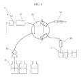
- FIG. 4 of the present application shows an example of the structure of a typical liquid chromatography device.
- the liquid chromatography device X shown in the figure includes a column 91, a detector 92, a liquid feed pump 93, an injection valve 94, a sample suction nozzle 95 and a suction unit 96.
- the liquid feed pump 93 is connected to a mobile phase container B containing a mobile phase such as an eluant.
- the sample suction nozzle 95 is provided for drawing out the sample contained in a sample container C.
- the sample suction nozzle 95 is movable vertically or horizontally to successively draw out the sample contained in different sample containers C.
- the suction unit 96 is used to suck the sample into the injection valve 94.
- the sample drawn into the injection valve 94 is first introduced into the column 91 for allowing the sample to be adsorbed to the filler in the column 91. Then, the eluant in the mobile phase container B is fed into the column 91 by using the liquid feed pump 93, whereby measurement by the detector 92 is performed. The sample adsorbed to the filler is desorbed by the eluant and separated into components in the column 91. The detector 92 detects each separated component by e.g. measuring the absorbance.
- the introduction of the sample into the injection valve 94, introduction of the sample into the column 91 or introduction of the eluant into the column are performed properly by appropriately changing the flow passage in the injection valve 94. Thereafter, the sample suction nozzle 95 is moved for attachment to a next sample container C different from the previous sample container C, and the sample contained in this sample container C is drawn into the injection valve 94. Repeating this operation allows successive analysis of samples from different sample containers C.
- the mobile phase container B for containing an eluant is designed to have a relatively large volume to achieve successive analysis of a number of samples.
- gas enters the column 91, which hinders proper sample analysis and may further cause a failure of the device.
- a liquid level detection sensor or the like is provided so that when the remaining amount of the eluant falls below a predetermined amount, the sensor detects it and the container is replaced with a new mobile phase container B full of eluant.
- the used mobile phase container B is disposed of.
- the present invention has been proposed under the circumstances described above. It is therefore an object of the present invention to provide an analyzing device that allows a liquid for use in analysis to be used completely without being wasted.
- an analyzing device comprising a feeder for feeding a liquid for use in analysis from a container containing the liquid, a storage chamber for temporarily storing the liquid from the container, and a liquid level detector for detecting the level of the liquid in the storage chamber.
- the analyzing device is a liquid chromatography device comprising a column containing a filler, and an injection valve capable of introducing a sample into the column and also capable of introducing a liquid mobile phase as the liquid into the column.
- the storage chamber is provided between the container and the injection valve.
- the feeder feeds the liquid mobile phase in the container to the column via the injection valve.
- the feeder comprises a gas transfer pump connected to anupperportion of the storage chamber for discharging the gas in the storage chamber to the outside to reduce the pressure in the storage chamber to allow the liquid mobile phase in the container to be introduced into the storage chamber; and a liquid feed pump for feeding the liquid mobile phase in the container to the injection valve via the storage chamber, the liquid feed pump being provided between the storage chamber and the injection valve.
- the analyzing device further comprises a controller that actuates the gas transfer pump when the position of the liquid level detected by the liquid level detector is lower than a predetermined height and stops actuating the gas transfer pump when the position of the liquid level exceeds the predetermined height.
- the container or the storage chamber is provided with a check valve that allows outside air to enter when the inside of the storage chamber reaches a predetermined negative pressure.
- the storage chamber is provided with a discharge pipe for discharging the liquid mobile phase in the storage chamber toward the injection valve.
- the discharge pipe includes an end that opens sideways within the storage chamber.
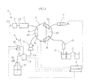
- Fig. 1 is a schematic structural view of an analyzing device according to the present invention exemplarily structured as a liquid chromatography device.
- the liquid chromatography device A separates a sample supplied from a sample container C into components for analysis, by using an eluant as a mobile phase supplied from a mobile phase container B.
- the liquid chromatography device includes a column 1, a detector 2, a mobile phase feeder 3, an injection valve 4, a storage chamber 5, a sample suction nozzle 6, a suction unit 7, piping connecting these parts, and a controller 8.
- the column 1 contains filler for adsorbing a sample introduced in the column and serves to control the adsorption/desorption of biological components relative to the filler and supply different kinds of biological components to the detector 2.
- the adsorbed sample is desorbed by the eluant.
- the desorbed sample and the eluant are discharged from the column 1 as an effluent and introduced into the detector 2 through a pipe L1.
- the detector 2 measures the absorbance of the effluent from the column 1 to analyze the components of the sample. After passing through the detector 2, the effluent is discharged through a pipe L2 and collected in e.g. a liquid waste tank, not shown.
- the mobile phase feeder 3 is provided for feeding the eluant in the mobile phase container B to the column 1 via the storage chamber 5 and the injection valve 4, and includes a liquid feed pump 31 and a gas transfer pump 32.
- the liquid feed pump 31 applies power for moving the eluant in the mobile phase container B to the injection valve 4 via the storage chamber 5.
- the liquid feed pump is provided at the pipe L3 connecting the storage chamber 5 and the injection valve 4. When the liquid feed pump 31 is actuated, the eluant in the storage chamber 5 is fed to the injection valve 4.
- the liquid feed pump 31 is also used for feeding the sample in the injection valve 4 to the column 1.
- the gas transfer pump 32 discharges the gas in the storage chamber 5 to the outside to allow the eluant in the mobile phase container B to move into the storage chamber 5.
- the gas transfer pump is provided at a pipe L4.
- the pipe L4 has an end that is open to the outside and another end connected to an exhaust passage 53 of the storage chamber 5 (see Fig. 3 ), which will be described later.
- the injection valve 4 serves to introduce a predetermined amount of sample, fed to the injection valve, into the column 1 and also introduce the eluant from the storage chamber 5 into the column 1.
- the injection valve 74 comprises e.g. a six-way valve and includes ports 4a, 4b, 4c and 4d.
- the ports 4c and 4d are connected by a loop-like passage 4E that is capable of retainingapredeterminedamount (e.g. 14 ⁇ m) of sample necessary for measurement.
- the injection valve 4 is designed to be able to change the connection target of the ports 4a, 4b, 4c and 4d. To feed the sample retained in the passage 4E to the column 1, as shown in Fig.
- the port 4d is connected to the liquid feed pump 31, whereas the port 4c is connected to the column 1.
- the sample between the ports 4c and 4d is fed to the column 1.
- the port 4a is connected to the liquid feed pump 31, whereas the port 4b is connected to the column 1.
- the eluant flows into the column 1 through the passage 4F between the ports 4a and 4b.
- the storage chamber 5 is provided for temporarily storing the eluant fed from the mobile phase container B.
- the storage chamber comprises e.g. a hermetically closed container made of a chemical-resistant material such as glass or synthetic resin.
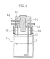
- the storage chamber 5 is provided with an eluant introduction pipe 51, an eluant discharge pipe 52, an exhaust passage 53 and a liquid level detection sensor 54.
- the volume of the mobile phase container B is about 1 L and the amount of the eluant used for a single time of analysis is about 2 mL
- the volume of the storage chamber 5 is about 30 mL.
- the eluant introduction pipe 51 is a pipe for introducing the eluant from the mobile phase container B into the storage chamber 5 and has an end that opens downward in an upper portion in the storage chamber 5.
- the eluant discharge pipe 52 is a pipe for discharging the eluant in the storage chamber 5 toward the injection valve 4, and is connected to the pipe L3 in an upper portion of the storage chamber 5.
- the eluant discharge pipe 52 includes a bent portion adjacent to the lower end, and the bent portion includes an end that opens sideways near the bottom of the storage chamber 5.
- the exhaust passage 53 is a passage for discharging the gas in the storage chamber 5 to the outside, and is connected to the pipe L4 at an upper portion of the storage chamber 5.
- the liquid level detection sensor 54 comprises e.g. an optical sensor such as a photosensor and detects the position of the liquid level S of the eluant in the storage chamber 5. In this embodiment, when the liquid level S reaches a full liquid level position Sf, which is a position reached when the chamber is full of liquid, the liquid level detection sensor 54 outputs a full liquid detection signal.
- the liquid level detection sensor 54 is not limited to a sensor that outputs what is called ON/OFF signals to indicate whether or not the position of the liquid level S is higher than a predetermined level, but may be e.g, a sensor that is capable of continuously detecting the position of the liquid level S relative to the liquid level detection sensor 54.
- the mobile phase container B may comprise an aluminum package of a non-fixed shape or a plastic container of a fixed shape. In this embodiment, an aluminum package is suitably employed. An eluant is loaded in the mobile phase container B.
- the mobile phase container B is provided with a check valve 33 for allowing outside air to enter when the internal pressure reaches a predetermined negative pressure.
- the sample suction nozzle 6 is provided for drawing the sample contained in the sample container C.
- a sample such as blood of a human body is contained.
- the sample suctionnozzle 6 is movable vertically or horizontally to successively draw the sample in different sample containers C.
- the suction unit 7 is used to suck the sample into the injection valve 4.
- the controller 8 controls the operation of each part of the liquid chromatography device A. The process of introducing the sample and the eluant into the column 1 under control by the controller 8 is described below. First, as shown in Fig. 1 , the controller 8 causes the suction unit 7 to draw the sample from a first sample container C into the passage 4E of the injection valve 4 via the sample suction nozzle 6. By this operation, a predetermined amount of sample is introduced into the passage 4E.
- the controller 8 rotates the injection valve 4 so that the port 4c is connected to the column 1 and the port 4d is connected to the liquid feed pump 31. Then, the controller 8 controls the liquid feed pump 31 so that the sample in the passage 4E between the ports 4c and 4d is fed into the column 1. Thus, the sample is introduced into the column 1 and adsorbed to the filler. Then, the controller 8 rotates the injection valve 4 so that the port 4a is connected to the liquid feed pump 31 and the port 4b is connected to the column 1. The controller 8 then controls the liquid feed pump 31 so that the eluant is fed from the storage chamber 5 into the column 1. The eluant fed into the column 1 desorbs the sample from the filler, whereby an effluent is produced. The effluent is subj ected to measurement by the detector 2, whereby the result of the first time of analysis is obtained.
- the controller 8 moves the sample suction nozzle 6 to attach the sample suction nozzle 6 to a second sample container C. Thereafter, the liquid feed pump 31 and the injection valve 4 are controlled in the same manner as in the first time of analysis, whereby the result of the second time of analysis is obtained. By repeating the same control, the third and the subsequent analysis are successively performed.
- the controller 8 also controls the operation of the gas transfer pump 32 to introduce the eluant in the mobile phase container B into the storage chamber 5. Specifically, the controller 8 performs control based on the information on the position of the liquid level S of the eluant in the storage chamber 5 detected by the liquid level detection sensor 54.
- the gas transfer pump 32 When the gas transfer pump 32 is actuated, the gas in the storage chamber 5 is discharged to the outside via the exhaust passage 53 and the pipe L4, whereby the pressure in the storage chamber 5 drops.
- the eluant in the mobile phase container B is introduced into the storage chamber 5 via the eluant introduction pipe 51.
- the controller 8 actuates the gas transfer pump 32 when the position of the liquid level S detected by the liquid level detection sensor 54 is lower than the predetermined height, i.e., the full liquid level position Sf.
- the controller 8 stops actuating the gas transfer pump 32 in accordance with the full liquid detection signal from the liquid level detection sensor 54.
- the storage chamber 5 is provided between the mobile phase container B and the injection valve 4.
- the eluant in the storage chamber 5 is consumed, and the eluant in the mobile phase container B is consumed accordingly.
- the eluant in the mobile phase container B is eventually emptied. At this point, however, the eluant still remains in the storage chamber 5.
- the remaining amount of the eluant in the storage chamber 5 is detected by the liquid level detection sensor 54.
- the mobile phase container B can be replaced with a new one when the remaining amount of eluant in the storage chamber 5 falls below a predetermined amount.
- the mobile phase container B to be replaced after the eluant in the container is completely used, so that the eluant for the analysis is not wasted by the replacement.
- the above-described structure allows a predetermined amount of eluant to constantly remain in the storage chamber 5. Thus, the sample analysis can be continued even during the replacement of the mobile phase container B, which is advantageous in terms of efficiency of the analysis work.
- the gas transfer pump 32 for introducing the eluant in the mobile phase container B into the storage chamber 5 is provided apart from the liquid feed pump 31 for feeding the eluant from the storage chamber 5.
- the gas transfer pump 32 for introducing the eluant in the mobile phase container B into the storage chamber 5.
- the controller 8 properly controls the gas transfer pump 32 to keep the amount of the eluant in the storage chamber 5 substantially constant. This contributes to stable supply of the eluant to the column 1.
- the mobile phase container B is provided with the check valve 33 that allows outside air to enter when the inside of the storage chamber 5 reaches a predetermined negative pressure. This prevents excessive negative pressure from being applied to the storage chamber 5 or the mobile phase container B when the eluant in the mobile phase container B is emptied. Thus, the eluant in the storage chamber 5 is smoothly supplied toward the injection valve 4. Thus, the eluant in the storage chamber 5 can be used almost completely without interruption. Moreover, by preventing generation of excessive negative pressure, it is possible to avoidproblems such as the application of undesirable load on the connecting portion of a cap or the like in e.g. replacing the mobile phase container B. Further, the application of overload on the liquid feed pump 31 or the parts such as a solenoidvalve arranged in the piping is also prevented.
- the eluant discharge pipe 52 for discharging the eluant toward the injection valve 4 has an end that opens sideways.
- the present invention is not limited to the foregoing embodiment.
- the specific structure of each part of the analyzing device according to the present invention maybe varied in many ways.
- a liquid chromatography device is described in the foregoing embodiment as an example of the analyzing device of the present invention, the structure other than a liquid chromatography device can be employed as the analyzing device of the present invention.
Landscapes
- Physics & Mathematics (AREA)
- General Physics & Mathematics (AREA)
- Analytical Chemistry (AREA)
- Biochemistry (AREA)
- Pathology (AREA)
- Health & Medical Sciences (AREA)
- Life Sciences & Earth Sciences (AREA)
- Chemical & Material Sciences (AREA)
- Electromagnetism (AREA)
- Immunology (AREA)
- General Health & Medical Sciences (AREA)
- Fluid Mechanics (AREA)
- Thermal Sciences (AREA)
- Sampling And Sample Adjustment (AREA)
- Treatment Of Liquids With Adsorbents In General (AREA)
- Automatic Analysis And Handling Materials Therefor (AREA)
Applications Claiming Priority (2)
| Application Number | Priority Date | Filing Date | Title |
|---|---|---|---|
| JP2008259456 | 2008-10-06 | ||
| PCT/JP2009/067218 WO2010041594A1 (ja) | 2008-10-06 | 2009-10-02 | 分析装置 |
Publications (3)
| Publication Number | Publication Date |
|---|---|
| EP2345895A1 true EP2345895A1 (de) | 2011-07-20 |
| EP2345895A4 EP2345895A4 (de) | 2013-03-27 |
| EP2345895B1 EP2345895B1 (de) | 2020-09-09 |
Family
ID=42100545
Family Applications (1)
| Application Number | Title | Priority Date | Filing Date |
|---|---|---|---|
| EP09819129.9A Active EP2345895B1 (de) | 2008-10-06 | 2009-10-02 | Analysegerät für flüssigchromatographie mit einem spender für mobile phase und mit einem speicherbehälter für mobile phase |
Country Status (5)
| Country | Link |
|---|---|
| US (1) | US20110179856A1 (de) |
| EP (1) | EP2345895B1 (de) |
| JP (1) | JP5442627B2 (de) |
| CN (1) | CN102171561B (de) |
| WO (1) | WO2010041594A1 (de) |
Cited By (2)
| Publication number | Priority date | Publication date | Assignee | Title |
|---|---|---|---|---|
| FR3033261A1 (fr) * | 2015-03-06 | 2016-09-09 | Centre Nat De La Rech Scient - Cnrs | Appareil pour separer des composes chimiques presents dans un echantillon avec un eluant corrosif |
| WO2024091154A1 (en) * | 2022-10-28 | 2024-05-02 | Biotage Ab | Method for monitoring liquid content |
Families Citing this family (6)
| Publication number | Priority date | Publication date | Assignee | Title |
|---|---|---|---|---|
| JP5646902B2 (ja) * | 2010-07-26 | 2014-12-24 | アークレイ株式会社 | 液体クロマトグラフィ装置およびインジェクションバルブ |
| CN104237427B (zh) * | 2014-09-12 | 2016-04-13 | 华南理工大学 | 一种液相色谱流动相预警装置 |
| JP6048552B1 (ja) * | 2015-08-21 | 2016-12-21 | 株式会社 イアス | オンライン移送した分析試料の分析システム |
| CN111094971A (zh) * | 2017-09-19 | 2020-05-01 | 株式会社岛津制作所 | 液相色谱仪以及液量探测方法 |
| EP4328581A4 (de) * | 2021-04-19 | 2025-04-23 | Hitachi High-Tech Corporation | Flüssigkeitschromatograph und steuerverfahren für flüssigkeitschromatograph |
| CN117723690B (zh) * | 2024-02-01 | 2024-04-19 | 广州恒广复合材料有限公司 | 一种聚季铵盐-51检测设备及其检测方法 |
Family Cites Families (16)
| Publication number | Priority date | Publication date | Assignee | Title |
|---|---|---|---|---|
| JPS6227661A (ja) * | 1985-07-29 | 1987-02-05 | Shimadzu Corp | 高速液体クロマトグラフ |
| JPH0611392B2 (ja) * | 1985-11-29 | 1994-02-16 | 株式会社島津製作所 | 溶媒供給装置 |
| JPS6329759U (de) * | 1986-08-08 | 1988-02-26 | ||
| JPS63165720A (ja) * | 1986-12-26 | 1988-07-09 | Fujitsu Ltd | 液面レベル警報器付液体貯蔵タンク |
| EP0438184B1 (de) * | 1987-01-17 | 1994-10-05 | Jasco Corporation | Extraktionsvorrichtung |
| EP0346565A3 (de) * | 1988-06-15 | 1991-02-27 | Hewlett-Packard Company | Restriktionsheizung bei überkritischer Flüssigkeitschromatographie |
| US5112492A (en) * | 1990-12-11 | 1992-05-12 | Biotage Inc. | Automated bubble trap |
| JP2001058105A (ja) * | 1995-10-09 | 2001-03-06 | Takeda Chem Ind Ltd | 脱気装置 |
| CN2250521Y (zh) * | 1995-12-11 | 1997-03-26 | 顾好粮 | 气压恒流式液相色谱输液装置 |
| JP3838711B2 (ja) * | 1996-09-24 | 2006-10-25 | 積水化学工業株式会社 | 液体クロマトグラフ |
| US6133076A (en) * | 1999-08-24 | 2000-10-17 | Semiconductor Energy Laboratory Co., Ltd. | Manufacturing method of semiconductor |
| US6382928B1 (en) * | 2000-11-28 | 2002-05-07 | Kun-Lin Chang | Miniature air pump |
| US7112308B2 (en) * | 2003-07-15 | 2006-09-26 | Smith Strom W | Sulfur trap sealing device |
| JP4622575B2 (ja) * | 2005-02-22 | 2011-02-02 | 東ソー株式会社 | 気泡除去装置 |
| JP2007056840A (ja) * | 2005-08-26 | 2007-03-08 | Yamaha Motor Co Ltd | エンジン装置における燃料タンクの燃料蒸気排出構造 |
| US20080183401A1 (en) * | 2007-01-29 | 2008-07-31 | Teledyne Isco, Inc. | Apparatuses and methods for wireless monitoring and control of enviromental sampling and chromatographic apparatuses |
-
2009
- 2009-10-02 US US13/121,878 patent/US20110179856A1/en not_active Abandoned
- 2009-10-02 WO PCT/JP2009/067218 patent/WO2010041594A1/ja not_active Ceased
- 2009-10-02 JP JP2010532885A patent/JP5442627B2/ja active Active
- 2009-10-02 EP EP09819129.9A patent/EP2345895B1/de active Active
- 2009-10-02 CN CN200980139196.XA patent/CN102171561B/zh active Active
Cited By (3)
| Publication number | Priority date | Publication date | Assignee | Title |
|---|---|---|---|---|
| FR3033261A1 (fr) * | 2015-03-06 | 2016-09-09 | Centre Nat De La Rech Scient - Cnrs | Appareil pour separer des composes chimiques presents dans un echantillon avec un eluant corrosif |
| WO2016142609A1 (fr) * | 2015-03-06 | 2016-09-15 | Centre National De La Recherche Scientifique - Cnrs | Appareil pour séparer des composés chimiques présents dans un échantillon avec un éluant corrosif |
| WO2024091154A1 (en) * | 2022-10-28 | 2024-05-02 | Biotage Ab | Method for monitoring liquid content |
Also Published As
| Publication number | Publication date |
|---|---|
| CN102171561A (zh) | 2011-08-31 |
| WO2010041594A1 (ja) | 2010-04-15 |
| EP2345895B1 (de) | 2020-09-09 |
| JPWO2010041594A1 (ja) | 2012-03-08 |
| JP5442627B2 (ja) | 2014-03-12 |
| EP2345895A4 (de) | 2013-03-27 |
| CN102171561B (zh) | 2014-11-05 |
| US20110179856A1 (en) | 2011-07-28 |
Similar Documents
| Publication | Publication Date | Title |
|---|---|---|
| EP2345895B1 (de) | Analysegerät für flüssigchromatographie mit einem spender für mobile phase und mit einem speicherbehälter für mobile phase | |
| US8522628B2 (en) | Liquid sample analyzing apparatus and liquid sample introducing apparatus | |
| US7819029B2 (en) | Automated pipette machine | |
| EP3026437B1 (de) | Probenanalysegerät | |
| JP2002517716A (ja) | 試料洗浄ステーションアセンブリ | |
| CN104520717B (zh) | 分析装置 | |
| EP1933982B1 (de) | System und verfahren zum kontinuierlichen überführen und verarbeiten von flüssigkeiten | |
| EP2730909B1 (de) | Festphasenextraktionsvorrichtung und viskositätsmessvorrichtung | |
| EP2668988B1 (de) | Kanalblasenreduzierungsvorrichtung, Kanalblasenreduzierungsprogramm, Kanalblasenreduzierungsverfahren, Flüssigkeitsbereitstellungsvorrichtung und Chromatographievorrichtung | |
| JPH03183947A (ja) | 分析器具用投与装置 | |
| JP4622575B2 (ja) | 気泡除去装置 | |
| US8939018B2 (en) | Analyzing device and method for controlling same | |
| EP2075586A1 (de) | Spender | |
| JP2004003916A (ja) | 液体吸排ノズルおよび液体吸排装置 | |
| US20020106319A1 (en) | Sequential injection liquid-liquid extraction | |
| JP2012247440A (ja) | 液体試料分析装置及び液体試料導入装置 | |
| CN212321648U (zh) | 一种全自动分析仪 | |
| CN201007717Y (zh) | 大量移液吸头快速装填装置 | |
| JP5802105B2 (ja) | 試薬容器を安全に空にし、かつ充填するための装置及び方法 | |
| CN119757627A (zh) | 一种纳升液相色谱仪的进样装置及进样方法 |
Legal Events
| Date | Code | Title | Description |
|---|---|---|---|
| PUAI | Public reference made under article 153(3) epc to a published international application that has entered the european phase |
Free format text: ORIGINAL CODE: 0009012 |
|
| 17P | Request for examination filed |
Effective date: 20110426 |
|
| AK | Designated contracting states |
Kind code of ref document: A1 Designated state(s): AT BE BG CH CY CZ DE DK EE ES FI FR GB GR HR HU IE IS IT LI LT LU LV MC MK MT NL NO PL PT RO SE SI SK SM TR |
|
| AX | Request for extension of the european patent |
Extension state: AL BA RS |
|
| DAX | Request for extension of the european patent (deleted) | ||
| A4 | Supplementary search report drawn up and despatched |
Effective date: 20130225 |
|
| RIC1 | Information provided on ipc code assigned before grant |
Ipc: G01N 30/26 20060101AFI20130219BHEP Ipc: G01N 30/20 20060101ALI20130219BHEP Ipc: G01F 23/292 20060101ALI20130219BHEP |
|
| RAP1 | Party data changed (applicant data changed or rights of an application transferred) |
Owner name: ARKRAY, INC. |
|
| STAA | Information on the status of an ep patent application or granted ep patent |
Free format text: STATUS: EXAMINATION IS IN PROGRESS |
|
| 17Q | First examination report despatched |
Effective date: 20170519 |
|
| GRAP | Despatch of communication of intention to grant a patent |
Free format text: ORIGINAL CODE: EPIDOSNIGR1 |
|
| STAA | Information on the status of an ep patent application or granted ep patent |
Free format text: STATUS: GRANT OF PATENT IS INTENDED |
|
| INTG | Intention to grant announced |
Effective date: 20200430 |
|
| RIN1 | Information on inventor provided before grant (corrected) |
Inventor name: TAKAGI TAKESHI Inventor name: AONO, TAKAFUMI |
|
| GRAS | Grant fee paid |
Free format text: ORIGINAL CODE: EPIDOSNIGR3 |
|
| GRAA | (expected) grant |
Free format text: ORIGINAL CODE: 0009210 |
|
| STAA | Information on the status of an ep patent application or granted ep patent |
Free format text: STATUS: THE PATENT HAS BEEN GRANTED |
|
| AK | Designated contracting states |
Kind code of ref document: B1 Designated state(s): AT BE BG CH CY CZ DE DK EE ES FI FR GB GR HR HU IE IS IT LI LT LU LV MC MK MT NL NO PL PT RO SE SI SK SM TR |
|
| REG | Reference to a national code |
Ref country code: GB Ref legal event code: FG4D |
|
| REG | Reference to a national code |
Ref country code: AT Ref legal event code: REF Ref document number: 1312206 Country of ref document: AT Kind code of ref document: T Effective date: 20200915 Ref country code: CH Ref legal event code: EP |
|
| REG | Reference to a national code |
Ref country code: IE Ref legal event code: FG4D |
|
| REG | Reference to a national code |
Ref country code: DE Ref legal event code: R096 Ref document number: 602009062755 Country of ref document: DE |
|
| REG | Reference to a national code |
Ref country code: LT Ref legal event code: MG4D |
|
| PG25 | Lapsed in a contracting state [announced via postgrant information from national office to epo] |
Ref country code: NO Free format text: LAPSE BECAUSE OF FAILURE TO SUBMIT A TRANSLATION OF THE DESCRIPTION OR TO PAY THE FEE WITHIN THE PRESCRIBED TIME-LIMIT Effective date: 20201209 Ref country code: BG Free format text: LAPSE BECAUSE OF FAILURE TO SUBMIT A TRANSLATION OF THE DESCRIPTION OR TO PAY THE FEE WITHIN THE PRESCRIBED TIME-LIMIT Effective date: 20201209 Ref country code: LT Free format text: LAPSE BECAUSE OF FAILURE TO SUBMIT A TRANSLATION OF THE DESCRIPTION OR TO PAY THE FEE WITHIN THE PRESCRIBED TIME-LIMIT Effective date: 20200909 Ref country code: FI Free format text: LAPSE BECAUSE OF FAILURE TO SUBMIT A TRANSLATION OF THE DESCRIPTION OR TO PAY THE FEE WITHIN THE PRESCRIBED TIME-LIMIT Effective date: 20200909 Ref country code: GR Free format text: LAPSE BECAUSE OF FAILURE TO SUBMIT A TRANSLATION OF THE DESCRIPTION OR TO PAY THE FEE WITHIN THE PRESCRIBED TIME-LIMIT Effective date: 20201210 Ref country code: SE Free format text: LAPSE BECAUSE OF FAILURE TO SUBMIT A TRANSLATION OF THE DESCRIPTION OR TO PAY THE FEE WITHIN THE PRESCRIBED TIME-LIMIT Effective date: 20200909 Ref country code: HR Free format text: LAPSE BECAUSE OF FAILURE TO SUBMIT A TRANSLATION OF THE DESCRIPTION OR TO PAY THE FEE WITHIN THE PRESCRIBED TIME-LIMIT Effective date: 20200909 |
|
| REG | Reference to a national code |
Ref country code: AT Ref legal event code: MK05 Ref document number: 1312206 Country of ref document: AT Kind code of ref document: T Effective date: 20200909 |
|
| REG | Reference to a national code |
Ref country code: NL Ref legal event code: MP Effective date: 20200909 |
|
| PG25 | Lapsed in a contracting state [announced via postgrant information from national office to epo] |
Ref country code: LV Free format text: LAPSE BECAUSE OF FAILURE TO SUBMIT A TRANSLATION OF THE DESCRIPTION OR TO PAY THE FEE WITHIN THE PRESCRIBED TIME-LIMIT Effective date: 20200909 Ref country code: PL Free format text: LAPSE BECAUSE OF FAILURE TO SUBMIT A TRANSLATION OF THE DESCRIPTION OR TO PAY THE FEE WITHIN THE PRESCRIBED TIME-LIMIT Effective date: 20200909 |
|
| PG25 | Lapsed in a contracting state [announced via postgrant information from national office to epo] |
Ref country code: EE Free format text: LAPSE BECAUSE OF FAILURE TO SUBMIT A TRANSLATION OF THE DESCRIPTION OR TO PAY THE FEE WITHIN THE PRESCRIBED TIME-LIMIT Effective date: 20200909 Ref country code: CZ Free format text: LAPSE BECAUSE OF FAILURE TO SUBMIT A TRANSLATION OF THE DESCRIPTION OR TO PAY THE FEE WITHIN THE PRESCRIBED TIME-LIMIT Effective date: 20200909 Ref country code: NL Free format text: LAPSE BECAUSE OF FAILURE TO SUBMIT A TRANSLATION OF THE DESCRIPTION OR TO PAY THE FEE WITHIN THE PRESCRIBED TIME-LIMIT Effective date: 20200909 Ref country code: PT Free format text: LAPSE BECAUSE OF FAILURE TO SUBMIT A TRANSLATION OF THE DESCRIPTION OR TO PAY THE FEE WITHIN THE PRESCRIBED TIME-LIMIT Effective date: 20210111 Ref country code: SM Free format text: LAPSE BECAUSE OF FAILURE TO SUBMIT A TRANSLATION OF THE DESCRIPTION OR TO PAY THE FEE WITHIN THE PRESCRIBED TIME-LIMIT Effective date: 20200909 Ref country code: RO Free format text: LAPSE BECAUSE OF FAILURE TO SUBMIT A TRANSLATION OF THE DESCRIPTION OR TO PAY THE FEE WITHIN THE PRESCRIBED TIME-LIMIT Effective date: 20200909 |
|
| PG25 | Lapsed in a contracting state [announced via postgrant information from national office to epo] |
Ref country code: AT Free format text: LAPSE BECAUSE OF FAILURE TO SUBMIT A TRANSLATION OF THE DESCRIPTION OR TO PAY THE FEE WITHIN THE PRESCRIBED TIME-LIMIT Effective date: 20200909 Ref country code: ES Free format text: LAPSE BECAUSE OF FAILURE TO SUBMIT A TRANSLATION OF THE DESCRIPTION OR TO PAY THE FEE WITHIN THE PRESCRIBED TIME-LIMIT Effective date: 20200909 Ref country code: IS Free format text: LAPSE BECAUSE OF FAILURE TO SUBMIT A TRANSLATION OF THE DESCRIPTION OR TO PAY THE FEE WITHIN THE PRESCRIBED TIME-LIMIT Effective date: 20210109 |
|
| REG | Reference to a national code |
Ref country code: CH Ref legal event code: PL |
|
| REG | Reference to a national code |
Ref country code: DE Ref legal event code: R097 Ref document number: 602009062755 Country of ref document: DE |
|
| PG25 | Lapsed in a contracting state [announced via postgrant information from national office to epo] |
Ref country code: MC Free format text: LAPSE BECAUSE OF FAILURE TO SUBMIT A TRANSLATION OF THE DESCRIPTION OR TO PAY THE FEE WITHIN THE PRESCRIBED TIME-LIMIT Effective date: 20200909 Ref country code: LU Free format text: LAPSE BECAUSE OF NON-PAYMENT OF DUE FEES Effective date: 20201002 Ref country code: SK Free format text: LAPSE BECAUSE OF FAILURE TO SUBMIT A TRANSLATION OF THE DESCRIPTION OR TO PAY THE FEE WITHIN THE PRESCRIBED TIME-LIMIT Effective date: 20200909 |
|
| REG | Reference to a national code |
Ref country code: BE Ref legal event code: MM Effective date: 20201031 |
|
| PLBE | No opposition filed within time limit |
Free format text: ORIGINAL CODE: 0009261 |
|
| STAA | Information on the status of an ep patent application or granted ep patent |
Free format text: STATUS: NO OPPOSITION FILED WITHIN TIME LIMIT |
|
| 26N | No opposition filed |
Effective date: 20210610 |
|
| PG25 | Lapsed in a contracting state [announced via postgrant information from national office to epo] |
Ref country code: SI Free format text: LAPSE BECAUSE OF FAILURE TO SUBMIT A TRANSLATION OF THE DESCRIPTION OR TO PAY THE FEE WITHIN THE PRESCRIBED TIME-LIMIT Effective date: 20200909 Ref country code: LI Free format text: LAPSE BECAUSE OF NON-PAYMENT OF DUE FEES Effective date: 20201031 Ref country code: DK Free format text: LAPSE BECAUSE OF FAILURE TO SUBMIT A TRANSLATION OF THE DESCRIPTION OR TO PAY THE FEE WITHIN THE PRESCRIBED TIME-LIMIT Effective date: 20200909 Ref country code: BE Free format text: LAPSE BECAUSE OF NON-PAYMENT OF DUE FEES Effective date: 20201031 Ref country code: CH Free format text: LAPSE BECAUSE OF NON-PAYMENT OF DUE FEES Effective date: 20201031 |
|
| PG25 | Lapsed in a contracting state [announced via postgrant information from national office to epo] |
Ref country code: IE Free format text: LAPSE BECAUSE OF NON-PAYMENT OF DUE FEES Effective date: 20201002 |
|
| PG25 | Lapsed in a contracting state [announced via postgrant information from national office to epo] |
Ref country code: TR Free format text: LAPSE BECAUSE OF FAILURE TO SUBMIT A TRANSLATION OF THE DESCRIPTION OR TO PAY THE FEE WITHIN THE PRESCRIBED TIME-LIMIT Effective date: 20200909 Ref country code: MT Free format text: LAPSE BECAUSE OF FAILURE TO SUBMIT A TRANSLATION OF THE DESCRIPTION OR TO PAY THE FEE WITHIN THE PRESCRIBED TIME-LIMIT Effective date: 20200909 Ref country code: CY Free format text: LAPSE BECAUSE OF FAILURE TO SUBMIT A TRANSLATION OF THE DESCRIPTION OR TO PAY THE FEE WITHIN THE PRESCRIBED TIME-LIMIT Effective date: 20200909 |
|
| PG25 | Lapsed in a contracting state [announced via postgrant information from national office to epo] |
Ref country code: MK Free format text: LAPSE BECAUSE OF FAILURE TO SUBMIT A TRANSLATION OF THE DESCRIPTION OR TO PAY THE FEE WITHIN THE PRESCRIBED TIME-LIMIT Effective date: 20200909 |
|
| PGFP | Annual fee paid to national office [announced via postgrant information from national office to epo] |
Ref country code: DE Payment date: 20251021 Year of fee payment: 17 |
|
| PGFP | Annual fee paid to national office [announced via postgrant information from national office to epo] |
Ref country code: GB Payment date: 20251022 Year of fee payment: 17 |
|
| PGFP | Annual fee paid to national office [announced via postgrant information from national office to epo] |
Ref country code: IT Payment date: 20251024 Year of fee payment: 17 |
|
| PGFP | Annual fee paid to national office [announced via postgrant information from national office to epo] |
Ref country code: FR Payment date: 20251029 Year of fee payment: 17 |