EP2345818A1 - Teile für die kurbelwelle eines verbrennungsmotors oder kompressors, kurbelwelle, verbrennungsmotor und kompressor - Google Patents
Teile für die kurbelwelle eines verbrennungsmotors oder kompressors, kurbelwelle, verbrennungsmotor und kompressor Download PDFInfo
- Publication number
- EP2345818A1 EP2345818A1 EP09824363A EP09824363A EP2345818A1 EP 2345818 A1 EP2345818 A1 EP 2345818A1 EP 09824363 A EP09824363 A EP 09824363A EP 09824363 A EP09824363 A EP 09824363A EP 2345818 A1 EP2345818 A1 EP 2345818A1
- Authority
- EP
- European Patent Office
- Prior art keywords
- crank
- crankshaft
- hole
- main journal
- pin
- Prior art date
- Legal status (The legal status is an assumption and is not a legal conclusion. Google has not performed a legal analysis and makes no representation as to the accuracy of the status listed.)
- Granted
Links
- 238000002485 combustion reaction Methods 0.000 title claims abstract description 55
- 238000009434 installation Methods 0.000 claims description 11
- 238000013461 design Methods 0.000 description 6
- 238000005461 lubrication Methods 0.000 description 4
- 238000005516 engineering process Methods 0.000 description 3
- 238000004519 manufacturing process Methods 0.000 description 3
- 230000007246 mechanism Effects 0.000 description 3
- 230000002093 peripheral effect Effects 0.000 description 3
- 230000009471 action Effects 0.000 description 2
- 238000006243 chemical reaction Methods 0.000 description 2
- 238000005553 drilling Methods 0.000 description 2
- 230000000694 effects Effects 0.000 description 2
- 238000000034 method Methods 0.000 description 2
- 230000000737 periodic effect Effects 0.000 description 2
- 238000005299 abrasion Methods 0.000 description 1
- 230000009286 beneficial effect Effects 0.000 description 1
- 230000008901 benefit Effects 0.000 description 1
- 230000008859 change Effects 0.000 description 1
- 238000004891 communication Methods 0.000 description 1
- 238000006073 displacement reaction Methods 0.000 description 1
- 238000010438 heat treatment Methods 0.000 description 1
- 230000006872 improvement Effects 0.000 description 1
- 238000003754 machining Methods 0.000 description 1
- 238000003801 milling Methods 0.000 description 1
- 239000003595 mist Substances 0.000 description 1
- 238000012986 modification Methods 0.000 description 1
- 230000004048 modification Effects 0.000 description 1
- 230000036961 partial effect Effects 0.000 description 1
- 238000003825 pressing Methods 0.000 description 1
- 230000008569 process Effects 0.000 description 1
- 238000012545 processing Methods 0.000 description 1
Images


Classifications
-
- F—MECHANICAL ENGINEERING; LIGHTING; HEATING; WEAPONS; BLASTING
- F16—ENGINEERING ELEMENTS AND UNITS; GENERAL MEASURES FOR PRODUCING AND MAINTAINING EFFECTIVE FUNCTIONING OF MACHINES OR INSTALLATIONS; THERMAL INSULATION IN GENERAL
- F16C—SHAFTS; FLEXIBLE SHAFTS; ELEMENTS OR CRANKSHAFT MECHANISMS; ROTARY BODIES OTHER THAN GEARING ELEMENTS; BEARINGS
- F16C3/00—Shafts; Axles; Cranks; Eccentrics
- F16C3/04—Crankshafts, eccentric-shafts; Cranks, eccentrics
- F16C3/06—Crankshafts
- F16C3/10—Crankshafts assembled of several parts, e.g. by welding by crimping
- F16C3/12—Crankshafts assembled of several parts, e.g. by welding by crimping releasably connected
-
- F—MECHANICAL ENGINEERING; LIGHTING; HEATING; WEAPONS; BLASTING
- F16—ENGINEERING ELEMENTS AND UNITS; GENERAL MEASURES FOR PRODUCING AND MAINTAINING EFFECTIVE FUNCTIONING OF MACHINES OR INSTALLATIONS; THERMAL INSULATION IN GENERAL
- F16C—SHAFTS; FLEXIBLE SHAFTS; ELEMENTS OR CRANKSHAFT MECHANISMS; ROTARY BODIES OTHER THAN GEARING ELEMENTS; BEARINGS
- F16C3/00—Shafts; Axles; Cranks; Eccentrics
- F16C3/04—Crankshafts, eccentric-shafts; Cranks, eccentrics
- F16C3/06—Crankshafts
- F16C3/14—Features relating to lubrication
-
- F—MECHANICAL ENGINEERING; LIGHTING; HEATING; WEAPONS; BLASTING
- F16—ENGINEERING ELEMENTS AND UNITS; GENERAL MEASURES FOR PRODUCING AND MAINTAINING EFFECTIVE FUNCTIONING OF MACHINES OR INSTALLATIONS; THERMAL INSULATION IN GENERAL
- F16C—SHAFTS; FLEXIBLE SHAFTS; ELEMENTS OR CRANKSHAFT MECHANISMS; ROTARY BODIES OTHER THAN GEARING ELEMENTS; BEARINGS
- F16C2226/00—Joining parts; Fastening; Assembling or mounting parts
- F16C2226/10—Force connections, e.g. clamping
- F16C2226/16—Force connections, e.g. clamping by wedge action, e.g. by tapered or conical parts
-
- F—MECHANICAL ENGINEERING; LIGHTING; HEATING; WEAPONS; BLASTING
- F16—ENGINEERING ELEMENTS AND UNITS; GENERAL MEASURES FOR PRODUCING AND MAINTAINING EFFECTIVE FUNCTIONING OF MACHINES OR INSTALLATIONS; THERMAL INSULATION IN GENERAL
- F16C—SHAFTS; FLEXIBLE SHAFTS; ELEMENTS OR CRANKSHAFT MECHANISMS; ROTARY BODIES OTHER THAN GEARING ELEMENTS; BEARINGS
- F16C2226/00—Joining parts; Fastening; Assembling or mounting parts
- F16C2226/50—Positive connections
- F16C2226/60—Positive connections with threaded parts, e.g. bolt and nut connections
-
- Y—GENERAL TAGGING OF NEW TECHNOLOGICAL DEVELOPMENTS; GENERAL TAGGING OF CROSS-SECTIONAL TECHNOLOGIES SPANNING OVER SEVERAL SECTIONS OF THE IPC; TECHNICAL SUBJECTS COVERED BY FORMER USPC CROSS-REFERENCE ART COLLECTIONS [XRACs] AND DIGESTS
- Y10—TECHNICAL SUBJECTS COVERED BY FORMER USPC
- Y10T—TECHNICAL SUBJECTS COVERED BY FORMER US CLASSIFICATION
- Y10T74/00—Machine element or mechanism
- Y10T74/21—Elements
- Y10T74/2173—Cranks and wrist pins
Definitions
- the present invention relates to a crankshaft of an engine or compressor, in particular, to parts for crankshaft of crank circular slide block type internal combustion engine or compressor, and to a crankshaft constituted by the parts.
- the invention also provides an internal combustion engine and a compressor comprising the above-described crankshaft.
- a conversion between a reciprocating motion of a piston and a rotary motion of a crankshaft is required to be realized, wherein the reciprocating motion of the piston is converted into the rotary motion of the crankshaft in the reciprocating type internal combustion engine, while the rotary motion of the crankshaft is converted into the reciprocating motion of the piston in the reciprocating type compressor.
- the above-described conversion requires the use of a crank-link mechanism. The machine becomes bulky and heavy due to the existence of links in the crank-link mechanism, making it impossible to a complete balance.
- Chinese patent CN85100359A discloses a "reciprocating piston type internal combustion engine with crank-dual circular slide block"
- Chinese patent ZL95111404.2 protects a “reciprocating piston type internal combustion engine with crank-dual circular slide block”
- Chinese patent ZL95111403.4 protects a "reciprocating piston type internal combustion engine with crank-multiple circular slide block”.
- a common feature of the above internal combustion engines is that a thorough improvement is made on the crank-link mechanism of internal combustion engine in known technologies, by use of substituting the link with a circular slide block having an eccentric circular hole.
- the eccentric circular slide block is of a cylinder shape and is provided with an eccentric circular hole which is in parallel with the axis of the cylinder and passed through by a crank pin of the crankshaft.
- a piston of the internal combustion engine includes crown portions at both ends thereof and a guide portion connecting the crown portions, wherein the guide portion is provided with a circular hole thereon whose inside diameter surface matches with an outside diameter surface of the circular slide block so that the circular slide block is placed into the circular hole of the guide portion of the piston which matches with the outer periphery of the circular slide block.
- crankshaft In the above discussed crank circular slide block type internal combustion engine or compressor, the crankshaft remains to be an indispensable part.
- the crankshaft has a main journal and a crank pin, wherein the main journal is used for supporting the crankshaft on the machine body by means of a bearing, and the crank pin passes through the eccentric circular hole of the circular slide block. Since the diameter of the main journal is larger than that of the crank pin, the main journal at both ends will necessarily completely enclose the left and right sides of the axis of the crank pin. Therefore, the problem with how to fit the circular slide block over the crank pin must be taken into consideration.
- the circular slide block as a split structure, i.e., the circular slide block is divided into two halves: a left part and a right part that are semi-circle respectively. Upon installation, the left part and the right part fit over the crank pin by facing them each other, and then bringing the two parts into an integral part by means of a lock-up structure.
- the circular slide block itself is small in size and the eccentric circular hole is also required to be provided, making the space for arranging the lock up structure limited.
- the circular slide block is subject to a very large force when the engine is in operation, therefore the lock up structure tends to fail. Therefore, this kind of circular slide block having split structure is not an optimum solution.
- the technical problem to be solved by the invention is to provide parts for crankshaft of an internal combustion engine or compressor, which cooperate with each other to form the crankshaft.
- the crankshaft formed by such a combination facilitates a convenient installation of the circular slide block on the crank pin, is easy to manufacture and assemble, is fixed firmly, and is insusceptible to fail. Moreover, the phase relationships between/among the parts remain unchanged after they are disassembled and re-assembled.
- the invention also provides an internal combustion engine and compressor using the above crankshaft.
- the parts for crankshaft of an internal combustion engine or compressor provided by the invention include two portions of a single throw main journal and a crank pin, wherein the crank pin extends out perpendicularly to the single throw main journal and has an axis that is offset relative to the axis of the main journal of the crankshaft, a front end that is tapered, at least one first positioning semi-hole is provided on a conical surface of the tapered end, starting from a small diameter end or a large diameter end.
- the first positioning semi-hole can match with a second positioning semi-hole on the crankshaft so as to form a complete positioning pin hole; this part is called as single throw.
- the first positioning semi-hole is specifically provided in a taper direction.
- a structure for installing flywheel or other power output connection components is provided on an outer end face of the single throw main journal.
- a first crank arm provided for connecting them.
- the first crank arm is coaxial with the single throw main journal and has a diameter slightly larger than that of the single throw main journal.
- a ring groove is provided at a projection portion in the direction towards the outer end face of the single throw main journal.
- the outer rabbet of the ring groove is under cut.
- the ring groove is called as oil slinger; an oil passage is provided at the bottom of the ring groove and extended from the inside of the crank pin to an oil orifice of the surface of the crank pin.
- the axis of the first crank arm coincides with that of the single throw main journal.
- the axis of the first crank arm is provided eccentrically relative to that of the single throw main journal, and on a side away from the axis of the crank pin.
- a toothed segment including at least two teeth is provided on the crank pin.
- the toothed segment matches with a corresponding internal toothed segment on the piston.
- a projection portion is provided on the crank pin at a position symmetric with and toothed segment at an angle of 180° from the toothed segment.
- an antifriction boss is provided around the root portion of the crank pin.
- a threaded hole matching with a crank bolt is provided at the center of the front end face of the tapered end of the crank pin.
- the taper of the tapered end of the crank pin is within the taper range of self locking.
- a part for crankshaft of an internal combustion engine or compressor includes a crank main journal, wherein a tapered hole matching with a tapered end of a crank pin is provided on the crank main journal; the axis of the tapered hole is parallel with the axis of the crank main journal and is offset relative to the axis of the crank main journal; on the inside diameter surface of the taper hole, a second positioning semi-hole which corresponds to a first positioning semi-hole on a single throw matching therewith is provided from the small diameter end face or the large diameter end face; the second positioning semi-hole can form a complete positioning pin hole after combining the single throw with the part; the part is called as crank.
- the crank is provided on its inner end face facing the crank pin with a second crank arm.
- crank bolt installation space is provided on the crank; upon installation, a crank bolt is used to lock up the crank and the crank pin after they insertedly fit with each other.
- a structure for installing flywheel or other power output connection components is provided on an outer end face of the crank.
- weight-reducing holes are provided on the crank.
- an antifriction boss is provided on the inner end face of the crank centering on the position of contact between the crank pin and the crank.
- the invention provides a crankshaft of an internal combustion engine or compressor, the crankshaft includes a single throw and a crank matching with each other; the single throw is that provided by any of the preceding technical solutions; the crank is that provided by any of the preceding technical solutions; upon assembly of the crankshaft, the crank insertedly fits with the tapered end on the front end of the crank pin of the single throw using a tapered hole of the crank, and a positioning pin is inserted into a pin hole formed by a first positioning semi-hole and a second positioning semi-hole corresponding with each other, so as to ensure that the axis of the crank main journal coincides with that of the single throw main journal and is parallel with the center line of the crank pin.
- the invention also provides a part for crankshaft of an internal combustion engine or compressor, the part including a first crank pin, a double throw main journal and a second crank pin; wherein the first crank pin and the second crank pin extend from left and right end faces of the double throw main journal respectively; both the front ends of the first crank pin and the second crank pin are tapered ends; at least one first positioning semi-hole is provided on the circumferences of the tapered ends of the first crank pin and the second crank pin respectively; the first positioning semi-hole can match with a corresponding second positioning semi-hole on the crank or a crank single throw to form a complete positioning pin hole; the perpendicular distances from the axes of the two crank pins to the axis of the main journal are equal; this part is called as double throw.
- both the diameters of the first crank pin and the second crank pin are smaller than that of the double throw main journal, and a line for connecting an axle center of the first crank pin and a axle center of the double throw main journal forms an angle of 0-180°with a line for connecting an axle center of the second crank pin and the axle center of the double throw main journal.
- the invention also provides a part for crankshaft of an internal combustion engine or compressor, including two portions of a crank single throw main journal and a crank pin; the crank pin extends out perpendicularly to the crank single throw main journal and has an axis that is offset from the axis of the crank single throw main journal; a front end that is tapered, at least one first positioning semi-hole is provided on the circumference of the tapered end; the first positioning semi-hole can match with a corresponding second positioning semi-hole provided on a crank or a crank single throw to form a complete positioning pin hole; a tapered hole is provided on the end face of the crank single throw main journal that faces away from the crank pin; at least one second positioning semi-hole is provided on an inside diameter surface of the tapered hole; the distance from the axis of the tapered hole to the axis of the crank single throw main journal is equal to the distance from the axis of the crank pin to the axis of the single throw main journal of crank; the second positioning semi-hole matches with the corresponding first
- the invention provides a crankshaft of an internal combustion engine or compressor which includes at least one double throw according to preceding technical solutions and one crank matching therewith.
- the invention provides another crankshaft of an internal combustion engine or compressor which at least comprises one aforementioned double throw, one aforementioned single throw of crank and a crank matching with the crank pin of the aforementioned crank single throw or the double throw.
- the invention provides an internal combustion engine employing a crankshaft according to any of the preceding technical solutions.
- the invention provides a compressor employing a crankshaft according to any of the preceding technical solutions.
- the single throw or double throw provided by the invention each has a crank pin which is open at one end, so that the circular slide block can be installed directly on the crank pin. Further, through a combination with a crank or a crank single throw, etc, a complete crankshaft can be formed.
- the crankshaft formed by such a combination is easy to manufacture.
- the relative angular relationships among various parts can be easily determined by a positioning pin hole which is formed by a combination of the first and second positioning semi-holes drilled correspondingly in process.
- the phase relationships among various parts remain unchanged after they are disassembled and re-assembled.
- the circular slide block can be conveniently inserted into the crank pin before assembling the crankshaft. Therefore, the crankshaft formed by such a combination results in a very easy assembly of the internal combustion engine or compressor.
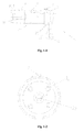
- Fig. 1-1 is a front view of a single throw of a modular crankshaft provided by a first embodiment of the invention
- Fig. 1-2 is a right side view of the single throw of the modular crankshaft provided by the first embodiment of the invention
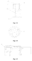
- Fig. 1-3 is a front view of a crank of the modular crankshaft provided by the first embodiment of the invention
- Fig. 1-4 is a left side view of the crank of the modular crankshaft provided by the first embodiment of the invention
- Fig. 1-5 is a front view of the modular crankshaft provided by the first embodiment of the invention after the crankshaft is combined;
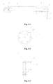
- Fig. 2-1 is a front view of a single throw of a modular crankshaft provided by a second embodiment of the invention
- Fig.2-2 is a front view of the crank of the modular crankshaft provided by the second embodiment of the invention.
- Fig.2-3 is a front view of the modular crankshaft provided by the second embodiment of the invention after the crankshaft is combined;
- Fig.3-1 is a front view of a single throw of a modular crankshaft provided by a third embodiment of the invention.
- Fig.3-2 is a right side view of the single throw of the modular crankshaft provided by the third embodiment of the invention.
- Fig.3-3 is a front view of the crank of the modular crankshaft provided by the third embodiment of the invention.
- Fig.3-4 is a left side view of the crank of the modular crankshaft provided by the third embodiment of the invention.
- Fig.3-5 is a front view of the modular crankshaft provided by the third embodiment of the invention after the crankshaft is combined;
- Fig.4-1 is a front view of a double throw of a modular crankshaft provided by a fourth embodiment of the invention.
- Fig.4-2 is a left side view of the double throw of the modular crankshaft provided by the fourth embodiment of the invention.
- Fig.4-3 is a front view of a single throw of the modular crankshaft provided by the fourth embodiment of the invention.
- Fig.4-4 is a right side view of the single throw of the modular crankshaft provided by the fourth embodiment of the invention.
- Fig.4-5 is a front view of a crank of the modular crankshaft provided by the fourth embodiment of the invention.
- Fig.4-6 is a left side view of the crank of the modular crankshaft provided by the fourth embodiment of the invention.
- Fig.4-7 is a schematic view of the modular crankshaft provided by the fourth embodiment of the invention after the crankshaft is combined.
- the first embodiment of the invention provides a modular crankshaft of a miniature two-stroke single-cylinder engine.
- the modular crankshaft includes a single throw and a crank which is combined therewith, both of which are assembled together to form a complete crankshaft.
- Fig. 1 illustrates this modular crankshaft, wherein Fig. 1-1 is a front view of the single throw of the modular crankshaft, Fig. 1-2 is a right side view of the single throw shown in Fig. 1-1 , Fig. 1-3 is a front view of the crank of the modular crankshaft, Fig. 1-4 is a left side view of the crank of the modular crankshaft, and Fig. 1-5 is a front view of the modular crankshaft after being combined.
- the single throw of the modular crankshaft includes three portions having axes in parallel with each other and connected in the following order: a single throw main journal 5, a first crank arm 22 and a crank pin 21. All of the three portions are cylindrical and have diameters different from each other.
- the single throw main journal 5 is located at one end of the single throw.
- the single throw main journal 5, together with a crank main journal 13, supports the modular crankshaft so as to provide a rotation axle center for the modular crankshaft; as shown in Fig. 1-2 , an outer end face of the single throw main journal 5 is provided with several threaded holes 12 for installing flywheel or other power output connection components (not shown).
- the outer end face of the single throw main journal 5 refers to the end face of the main journal 5 which is away from the crank pin 21 and faces the end face outside the crankshaft during the operation.
- the first crank arm 22 is coaxial with the single throw main journal 5 and has a diameter slightly larger than that of the single throw main journal 5. Besides, a ring groove is provided at a projection portion in the direction towards the outer end face of the single throw main journal 5. The outer rabbet of the ring groove inclines inwardly. The ring groove is called as oil slinger 4.
- the crank pin 21 is a cylinder that has a diameter smaller than that of the single throw main journal 5, and extends perpendicularly from the outer end face of the first crank arm 22.
- the axis of the crank pin 21 is offset to one side relative to a common axis of the single throw main journal 5 and the first crank arm 22.
- a toothed segment 7 including three teeth is provided on the outer periphery of the crank pin 21.
- a projection portion 20 is provided at a position forming an angle of 180° with the toothed segment 7.
- the front end of the crank pin 21 is a tapered end 9.
- a central hole 11 with a fine thread is provided axially at the center of the front end face of the tapered end 9.
- first positioning semi-holes 10-1 which extend in the tapering direction are provided along the outer peripheral surface of the tapered end 9.
- the first positioning semi-holes 10-1 may also begin from the large diameter end of the tapered end 9 and extend in the taper direction along its circumferential surface.
- the first positioning semi-holes 10-1 combine with second positioning semi-holes provided on the crank forms a complete positioning pin holes.
- An oil passage 6 is provided inside the pin body of the crank pin 21. One end of the oil passage 6 opens into the groove bottom of the oil slinger 4, and the other end thereof opens into an oil orifice 8 on the surface of the crank pin 21.
- crank shown in Fig.1-3 The crank comprises two portions connected axially in a straight line: a crank main journal 13 and a second crank arm 18.
- a tapered hole 15 is provided that matches with the taper of the tapered end 9 of the crank pin 21.
- a crank bolt installation space 14 is provided on an outer end face of the crank main journal 13 that faces away from the crank pin 21. This space is provided on the small end of the tapered hole 15 with a plane surface (not shown).
- An inner hole circular stop rabbet (not shown) is also provided on this space to locate magneto shaft when installing it.
- a threaded hole 3 for fixing the magneto shaft is also provided on the end face.
- Two second axial positioning semi-holes 10-2 are provided on the inside diameter face of the tapered hole 15 from the small diameter end face thereof in the taper direction of the tapered hole 15 (assuming that the first positioning semi-hole 10-1 matching with the second positioning semi-hole 10-2 begins from the small diameter end of the tapered end 9).
- the second positioning semi-holes 10-2 form complete circular holes (called positioning pin hole), combined with the first positioning semi-holes 10-1 on the tapered end 9 of the crank pin.
- several weight-reducing holes 2 can also be provided on the crank.
- crank and single throw above described can be combined to form a modular crankshaft.
- a circular slide block is disposed to fit over the crank pin 21 and a crankshaft gasket is used to adjust axial clearance.
- the crank is inserted into the crank pin by matching the tapered hole 15 with the tapered end 9 of the crank pin 21 and is adjusted by rotation in such a way that the first positioning semi-holes 10-1 and the second positioning semi-holes 10-2 which are symmetric engage with each other to form the complete circular positioning pin holes.
- the circular positioning pin holes have an opening at the side of the small diameter end of the tapered end 9.
- the beams of the two positioning pins are inserted into the positioning pin holes from the openings to realize a positioning of the crank and the single throw in the angular relationship therebetween. If the first positioning semi-holes 10-1 on the tapered end 9 of the crank pin begin from the large diameter end, the second positioning semi-holes 10-2 begin from the large diameter end face of the tapered hole 15 so that the opening of the positioning pin holes after the combination is on the large diameter end face and the beam of the positioning pin can also be inserted into the positioning pin hole through this opening. Finally, the crank bolt 17 is screwed into the central hole 11. The crankshaft and crank are pressed by a pre-tightening force. As such, the complete crank-circular slide block assembly is formed.
- the axis of the crank main journal 13 coincides with that of the single throw main journal 5 and the axis of the crank pin is parallel with that of the main journal so that the modular crankshaft can operate normally.
- the combination of the two first positioning semi-holes 10-1 and two second positioning semi-holes 10-2 can realize an accurate positioning of the crank and the single throw to ensure the above described geometric relationship after the positioning pin is inserted.
- the above structure in which the beam of the positioning pin connects two positioning semi-holes can also play the role of transmitting partial action force.
- the first positioning semi-holes 10-1 and second positioning semi-holes 10-2 are provided in two pairs, This number is quite reasonable.
- provision of only one pair of the first positioning semi-holes 10-1 and second positioning semi-holes 10-2 that match with each other can also perform the essential positioning function.
- the positioning accuracy is poor due to the restriction by fit tolerance between the positioning pin hole and the positioning pin, and the effect of transmitting action force is slightly poorer.
- the structure of positioning semi-hole is particularly described herein by taking the first positioning semi-hole 10-1 as an example.
- the first positioning semi-hole 10-1 is a recess that extends in the taper direction on the outer conical surface of the crank pin 21 of the single throw, and its cross section perpendicular to the axis of the crank pin 21 is a part of circle, which can be a semi-circle, or greater than or smaller than a semi-circle as long as it matches with the corresponding second positioning semi-hole 10-2 on the inside diameter surface of the tapered hole 15 of the crank so as to form a complete cylindrical hole in the said cross section.
- the positioning semi-hole is acquired by fitting the tapered end 9 of the single throw crank pin with the tapered hole 15 of the crank and then drilling the intersection therebetween.
- the separate milling process is not excluded.
- the first positioning semi-hole 10-1 and the second positioning semi-hole 10-2 will only extend by a distance along the conical surface and will not reach the other end face of the cone.
- the positioning pin hole is a blind hole.
- the taper of tapered face 9 of the crank pin 21 and the taper of the tapered hole 15 are small and within the range of self-locking. Therefore, in case that the crank bolt 17 is loosened, the crank pin 21 and crank will not be loosened during motion.
- the oil slinger 4 is a special design for the modular crankshaft. Oil mist exists in the cylinder block of engine. When the oil slinger rotates at a high speed, the oil will accumulate in the groove of the oil slinger under the action of centrifugal force and flow through the oil passage 6 and oil orifice 8 to the position where the circular slide block bearing contacts the crank pin 21 so as to provide lubrication oil for the modular crankshaft.
- the toothed segment 7 is a special design for the modular crankshaft used for single-cylinder engine.
- the purpose of the toothed segment 7 is to overcome the problem of active point.
- the toothed segment 7 cooperates with an internal toothed segment on the piston at a gear ratio of 2:1.
- a projection portion 20 is provided corresponding to the toothed segment 7.
- the projection portion 20 cooperates with the toothed segment 7 so that after the installation is completed, the crankshaft gasket will stably abut against an end face of the projection portion 20 that faces the crank so as to improve the stress state of the crankshaft gasket in motion.
- the second embodiment of the invention provides a modular crankshaft used for a three-cylinder air compressor.
- the modular crankshaft comprises a single throw and a crank to be combined with the single throw, both of which are assembled together to form a complete crankshaft.
- Fig.2 illustrates this modular crankshaft, wherein Fig.2-1 is a front view of the single throw of the modular crankshaft, Fig.2-2 is a front view of the crank of the modular crankshaft, and Fig.2-3 is a front view of the modular crankshaft after being combined.
- the single throw of the modular crankshaft includes three portions having axes in parallel with each other and connected in the following order: a single throw main journal 28, a first crank arm 29 and a crank pin 31.
- the structure of the single throw is substantially the same as that in the above-described first embodiment, and only the difference therebetween will be described below.
- a circular boss called antifriction boss 30, is provided at the position where the first crank arm 29 of the single throw contacts the root of the crank pin 31.
- the antifriction boss 30 is disposed around the root of the crank pin 31.
- the antifriction boss 30 is subject to fine machining and heat treatment for reducing abrasion in cooperation with crankshaft gasket. Thus, it is not required to machine and treat the entire crank arm plane and manufacture cost can be reduced.
- Fig.2-1 also shows that no toothed segment is provided on the crank pin 31. This is because this crankshaft is used for a multi-cylinder machine without the active point problem. Also, no oil slinger is provided on the single throw.
- a main oil passage 36 is axially provided.
- Several oil orifices 32 that lead to the main journal 28 and the outer periphery surface of the crank pin 31 are in communication with the main oil passage 36 so that the above-described oil path can provide lubrication oil to various bearings.
- An antifriction boss 27 is also provided on the crank of the modular crankshaft at the location facing the single throw.
- the combination manner of the modular crankshaft is the same as that of the first embodiment. Since the modular crankshaft is used for a three-cylinder air compressor, two circular slide blocks need to be installed on the crank pin.
- the third embodiment of the invention provides a modular crankshaft used for a gasoline engine having a displacement of 2.0 litre. Three circular slide blocks need to be used in the engine.
- the modular crankshaft also includes a single throw and a crank to be combined with the single throw, both of which are modular together to form a complete crankshaft.
- Fig.3 illustrates such a modular crankshaft
- Fig.3-1 is a front view of the single throw of the modular crankshaft
- Fig.3-2 is a right side view of the single throw shown in Fig.3-1
- Fig.3-3 is a front view of the crank of the modular crankshaft
- Fig.3-4 is a left side view of the crank of the modular crankshaft
- Fig.3-5 is a front view of the modular crankshaft after being combined.
- This embodiment is substantially the same as the first embodiment, and only the difference therebetween will be described below.
- the axis of the single throw main journal coincides with that of the first crank arm, and the axis of the crank pin does not lie in the same axis with the crankshaft rotation axis determined by the crank main journal and the single throw main journal.
- the crank pin will produce a centrifugal force, making the stress of the bearing supporting the main journal change periodically and thus affecting the life span.
- the crank arm is arranged to be an eccentric structure relative to the rotation axis of the crankshaft.
- the single throw of the modular crankshaft also comprises a single throw main journal 39, a first crank arm 42 and a crank pin 46, wherein the axis M-M of the first crank arm 42 does not coincide with the axis L-L (namely, the crankshaft rotation axis) of the single throw main journal 39 and lies on the side that is away from the axis N-N of the crank pin.
- the above three axes are coplanar and in parallel with each other.
- the axis of the crank pin 46 and the axis of the first crank arm 42 lie on both sides of the axis of the single throw main journal 39 respectively.
- the eccentric relationship between the first crank arm 42 and the single throw main journal 39 can be seen from Fig.3-2 .
- crank main journal and the second crank arm of the modular crankshaft also have the above-described positional relationship.
- the advantage of the above eccentric structure lies in that, when the modular crankshaft rotates, it rotates about a crankshaft rotation axis commonly formed by the main axis of the crank main journal and the main axis of the single throw main journal, and the rotation centroid of the first crank arm and the second crank arm and the rotation centroid of the crank pin lie on different sides of the crankshaft rotation axis.
- the centrifugal force generated by the first crank arm and the second crank arm offsets the centrifugal force generated by the crank pin so that the periodic variation amplitude of stress on the bearing supporting the crank main journal and the single throw main journal can be reduced, which is beneficial for prolonging the life span of engine.
- a ring groove is provided on the single throw main journal 39 to serve as an oil groove 40.
- oil orifices 41 that communicate the oil groove 40 with the main oil passage 44 are provided.
- lubrication oil can be fed into the main oil passage 44 from the oil groove 40.
- an inclined oil orifice 47 that communicates the surface of a cone 48 on the front end of the crank pin 46 with the main oil passage 44 is provided on the cone 48; an oil orifice 60 that communicates the surface of the crank main journal 52 and the inside diameter surface of the tapered hole 59 is provided on the crank.
- the inclined oil orifice 47 cooperates with the oil orifice 60 so as to feed oil to the bearing of the crank main journal 52.
- all the modular crankshafts are formed by a combination of a single throw and a crank.
- a modular crankshaft having a plurality of main journals is required.
- a modular crankshaft formed by a single throw, a double throw and a crank is required to be used.
- the fourth embodiment of the invention provides an embodiment of such a modular crankshaft.
- Fig.4 illustrates an modular crankshaft used for a two-stroke diesel engine having a power of 600KW
- Fig.4-1 is a front view of the double throw 101 of the modular crankshaft.
- the double throw 101 comprises a first crank pin 64, a double throw main journal 70 and a second crank pin 72.
- No dedicated crank arm is provided and it is the double throw main journal 70 that performs the function of the crank arm.
- This structure in which no crank arm is provided can actually be applied to the situation of the above first to third embodiments, wherein the first crank pin 64 and the second crank pin 72 extend perpendicularly from the left and right end faces of the main journal 70 respectively. Both the diameters of the first crank pin 64 and the second crank pin 72 are smaller than that of the double throw main journal 70.
- the axle centers of the first crank pin 64 and the second crank pin 72 are respectively located on two diameters of the main journal 70 that form an angle of 90°.
- the respective distances between their axle centers and the axle center of the main journal 70 equal to each other and the outer edge of the first crank pin 64 and the second crank pin 72 are located within the circumference of the double throw main journal 70.
- the geometrical relationship between the first crank pin 64 and the second crank pin 72 and the main journal 70 can be different from that in this embodiment as required.
- the lines connecting the two axle centers to the axis of the main journal 70 can vary within the range of 0-180° therebetween.
- a tapered end 61 is provided at the front end of the first crank pin 64, and a tapered end 76 is provided at the front end of the second crank pin 72.
- a first antifriction boss 67 is provided at a location where the root of the first crank pin 64 couples the end face of the double throw main journal 70; a second antifriction boss 71 is provided at a location where the root of the second crank pin 72 couples the end face of the double throw main journal 70.
- the arrangement and functions of the first antifriction boss 67 and the second antifriction boss 71 are the same as those in the second and third embodiments.
- a ring groove is provided on the outer peripheral surface of the main journal 70 at an axially central position to serve as an oil groove 69.
- the oil groove 69 communicates with a first main oil passage 66 of the first crank pin 64 and a second main oil passage 74 of the second crank pin 72 so as to feed lubrication oil to the bearing of the double throw main journal.
- the first main oil passage 66 and the second main oil passage 74 are respectively provided along the axes of the first crank pin 64 and the second crank pin 72, and communicate respectively with the first crank pin oil orifice 65 and the second crank pin oil orifice 73 that lead to the installation positions of various circular slide blocks of the engine.
- two first positioning semi-holes 62, 75 are respectively provided on the outer peripheral surfaces of tapered ends of two crank pins.
- the first positioning semi-holes combines with the second positioning semi-holes provided on the crank or crank single throw to form a complete positioning pin hole; central holes 63, 77 that cooperate with crank bolt are provided.
- Fig.4-3 illustrates a schematic view of the crank single throw of the modular crankshaft.
- the difference of this crank single throw from that in the above first to third embodiments lies in that the end face of the crank single throw main journal 86 of this crank single throw needs to match with a tapered end of the crank pin of the double throw when in combination.
- the crank single throw main journal 86 also serves as the crank.
- a tapered hole 88 is provided on the end face of the crank single throw main journal 86.
- a second positioning semi-hole 89 is provided on the inside diameter surface of the tapered hole 88.
- Other corresponding structures such as bolt installation space 87 are also provided.
- the second positioning semi-hole 89 corresponds to the first positioning semi-hole 62 or 75 on the crank pin of the double throw so as to form a complete positioning pin hole; the tapered hole 88 corresponds to the tapered end on the front end of the crank pin of the double throw.
- Fig.4-4 is a right side view of the crank single throw, in which the positional relationship between the tapered hole 88 and the crank pin 82 is shown.
- the tapered hole 88 and the crank pin 82 lie on both sides of the axis of the crank single throw main journal 86 and form an angle of 180°.
- crank arm is also not provided and no detailed discussion in given herein.
- Fig.4-5 illustrates the structure of the crank of this modular crankshaft. This crank matches with the crank pin of the crank single throw when in combination. This crank is not provided with a dedicated crank arm. Other parts are the same as those of the crank provided by the first embodiment of the invention, including a tapered hole 94 cooperating with the crank pin taper of the crank single throw, two second positioning semi-holes 95 matching with corresponding first positioning semi-holes on the crank pin of crank single throw, and crank bolt installation space 90.
- Fig.4-6 also illustrates that on the outer end face of the crank, several threaded holes 96 are provided for connecting power output shaft.
- the double throw 101 is connected at an intermediate position of the modular crankshaft.
- a first crank pin 100 of the double throw 101 cooperates with a crank single throw main journal of a first crank single throw 98
- a second crank pin 102 of the double throw 101 cooperates with a crank single throw main journal of a second crank single throw 103.
- the crank pin of the first crank single throw 98 matches with the first crank 97
- the crank pin of the second crank single throw 103 matches with the second crank 104.
- the angular relationship between the two crank pins of the double throw 101 is determined by the design of the double throw 101 itself; the angular relationship between the crank pin and the crank single throw can be determined by inserting a positioning pin into a complete positioning pin hole which is formed by a combination of corresponding first positioning semi-hole and second positioning semi-hole between the two crank pins of the double throw 101 and the crank single throw main journal; similarly, between the crank pin of the first crank single throw 98 and the first crank 97, a positioning is achieved by inserting a positioning pin into a complete positioning pin hole formed by a combination of corresponding first positioning semi-hole and second positioning semi-hole; a positioning is also achieved in the above manner between the crank pin of the second crank single throw 103 and the second crank 104.
- crank bolt is further required to lock up these parts.
- the axes of various main journals of the finally formed modular crank lie on the same straight line.
- Various crank pins form a certain angle with each other in space, namely, there appear several throws.
- the final modular crankshaft is a four-throw crankshaft.
- Each crank pin is provided with a circular slide block.
- the above fourth embodiment provides an example of a modular crankshaft which is formed by a flexible combination of a double throw, a crank single throw and a crank.
- the key feature thereof lies in that a tapered hole matching with a tapered face of crank pin of the double throw as well as a corresponding positioning pin hole are provided on the main journal of the crank single throw so that the crank single throw can simultaneously serve as the crank.
- the combination mode of the double throw, the crank single throw, the single throw and the crank is very flexible.
- Various combinations of the above parts can be made according to the enlightenment provided by the above embodiments so as to achieve various modular crankshaft.
- the angular fitting relationships between the crank pin and crank or between the crank pin of the double throw and corresponding crank single throw main journal are all ensured by connecting positioning pins of positioning semi-holes which match with each other, so that in the course of combination, the parts can conveniently form a crankshaft that meets the design requirements.
- the positioning semi-holes which correspond to each other are acquired by matching drilling in technology.
- each crank and crank pin are provided with two pairs of positioning semi-holes which match with each other to form two positioning pin holes. This number of positioning pin hole is the optimal design scheme.
- more than two pairs of positioning semi-holes can be provided as required to form more than two positioning pin holes, which could also bring about a well positioning effect.
- Even using just one pair of positioning semi-holes to form one positioning pin hole can also perform the positioning function. However, in this case, the positioning accuracy is somewhat lower and it only applies to applications with low demands.
- the above positioning semi-holes are provided in parallel with the taper direction of the tapered end of the crank pin or the taper direction of the tapered hole of the crank.
- This arrangement facilitates processing.
- they can also be provided in parallel with axes of the crank and crank pin or in other directions, as long as the first positioning semi-holes and the corresponding second positioning semi-holes can form complete positioning pin holes and positioning pins can be conveniently inserted so that the positioning of relative positional relationships of the crank, the crank pin, etc can be achieved.
- the two positioning semi-holes which match with each other do not necessarily assume just one half of the positioning pin hole respectively.
Landscapes
- Engineering & Computer Science (AREA)
- General Engineering & Computer Science (AREA)
- Ocean & Marine Engineering (AREA)
- Mechanical Engineering (AREA)
- Shafts, Cranks, Connecting Bars, And Related Bearings (AREA)
- Compressors, Vaccum Pumps And Other Relevant Systems (AREA)
Applications Claiming Priority (2)
| Application Number | Priority Date | Filing Date | Title |
|---|---|---|---|
| CN200810226417A CN101392789B (zh) | 2008-11-10 | 2008-11-10 | 用于内燃机或压缩机曲轴的零件、曲轴及内燃机、压缩机 |
| PCT/CN2009/073259 WO2010051708A1 (zh) | 2008-11-10 | 2009-08-14 | 用于内燃机或压缩机曲轴的零件、曲轴及内燃机、压缩机 |
Publications (3)
| Publication Number | Publication Date |
|---|---|
| EP2345818A1 true EP2345818A1 (de) | 2011-07-20 |
| EP2345818A4 EP2345818A4 (de) | 2016-04-20 |
| EP2345818B1 EP2345818B1 (de) | 2018-11-14 |
Family
ID=40493244
Family Applications (1)
| Application Number | Title | Priority Date | Filing Date |
|---|---|---|---|
| EP09824363.7A Not-in-force EP2345818B1 (de) | 2008-11-10 | 2009-08-14 | Teile für die kurbelwelle eines verbrennungsmotors oder kompressors, kurbelwelle, verbrennungsmotor und kompressor |
Country Status (6)
| Country | Link |
|---|---|
| US (1) | US9163658B2 (de) |
| EP (1) | EP2345818B1 (de) |
| JP (1) | JP5745418B2 (de) |
| CN (1) | CN101392789B (de) |
| BR (1) | BRPI0919117A2 (de) |
| WO (1) | WO2010051708A1 (de) |
Families Citing this family (9)
| Publication number | Priority date | Publication date | Assignee | Title |
|---|---|---|---|---|
| CN101392789B (zh) * | 2008-11-10 | 2012-08-29 | 北京中清能发动机技术有限公司 | 用于内燃机或压缩机曲轴的零件、曲轴及内燃机、压缩机 |
| CN101586570B (zh) * | 2009-04-22 | 2010-12-29 | 李新桥 | 淤泥泵过载保护结构 |
| CN101634354B (zh) * | 2009-06-24 | 2011-07-20 | 北京中清能发动机技术有限公司 | 一种曲柄圆滑块机构及其内燃机、压缩机 |
| CN101886693B (zh) * | 2010-07-02 | 2014-02-12 | 北京中清能发动机技术有限公司 | 一种曲柄圆滑块机构及设备 |
| ITBO20100444A1 (it) * | 2010-07-14 | 2012-01-15 | Diem Dipartimento Delle Costruzioni Meccaniche Nuc | Sistema albero motore a maschette portanti smontabili |
| CN102141079B (zh) * | 2011-02-22 | 2013-03-06 | 北京中清能发动机技术有限公司 | 曲柄、曲柄轴、组合曲轴及应用该曲轴的内燃机或压缩机 |
| CN105240395B (zh) * | 2014-06-24 | 2018-12-18 | 定远县众创科技服务有限公司 | 一种旋转半径可变偏心轴 |
| CN112049726A (zh) * | 2020-09-17 | 2020-12-08 | 徐玉国 | 凸轮挺杆式发动机 |
| CN113829094A (zh) * | 2021-10-20 | 2021-12-24 | 内江金鸿曲轴有限公司 | 一种曲轴中心孔加工工艺 |
Family Cites Families (31)
| Publication number | Priority date | Publication date | Assignee | Title |
|---|---|---|---|---|
| US1514768A (en) * | 1920-12-22 | 1924-11-11 | Skf Svenska Kullagerfab Ab | Crank shaft |
| US1690296A (en) * | 1920-12-22 | 1928-11-06 | Hirth Albert | Crank shaft |
| GB189753A (en) * | 1921-11-29 | 1923-11-15 | Cie Applic Mecaniques | Improvements in crank-shafts |
| GB252251A (en) * | 1925-02-21 | 1926-05-21 | Douglas Motors Ltd | Improvements in built-up crankshafts |
| FR690609A (fr) * | 1929-05-03 | 1930-09-24 | Perfectionnements relatifs à l'assemblage de deux parties d'arbres | |
| US1775054A (en) * | 1929-11-16 | 1930-09-02 | Clarence L Seegers | Wrist pin |
| GB399103A (en) * | 1932-03-10 | 1933-09-28 | Hoffmann Mfg Co Ltd | Improvements in and relating to crank shafts particularly for internal combustion engines |
| US2190411A (en) * | 1939-03-14 | 1940-02-13 | Berman G Kielmeyer | Sectional crankshaft |
| FR887207A (fr) * | 1941-07-24 | 1943-11-08 | Gnome Et Rhone Moteurs | Perfectionnements apportés aux arbres-vilebrequins à plusieurs coudes pour moteurs |
| US2359306A (en) * | 1941-12-24 | 1944-10-03 | Century Motors Corp | Engine crankshaft |
| US2566785A (en) * | 1946-08-16 | 1951-09-04 | Ben W Wheelis | Crankshaft construction |
| US2471982A (en) * | 1946-11-04 | 1949-05-31 | Shulda Melvin | Splice for crankshaft bearings |
| GB920385A (en) * | 1960-05-07 | 1963-03-06 | Ceskolovenske Zd Y Naftovych M | Improvements in and relating to crankshafts |
| JPS4825942Y1 (de) * | 1968-10-14 | 1973-07-28 | ||
| JPS4825942A (de) | 1971-08-09 | 1973-04-04 | ||
| FR2513711B1 (fr) * | 1981-09-25 | 1988-04-29 | Jeumont Schneider | Dispositif de liaison entre un arbre et un volant |
| CN85100359B (zh) | 1985-04-01 | 1988-12-14 | 黎正中 | 曲柄圆滑块往复活塞式压缩机 |
| CN85100358B (zh) | 1985-04-01 | 1988-01-13 | 黎正中 | 曲柄圆滑块往复活塞式内燃机 |
| JPH0734178Y2 (ja) * | 1989-10-20 | 1995-08-02 | 三菱自動車エンジニアリング株式会社 | 可変圧縮比エンジン |
| CN2066906U (zh) * | 1990-04-26 | 1990-12-05 | 宫立盛 | 双拐三缸压缩机 |
| JPH0573284U (ja) * | 1992-03-10 | 1993-10-08 | 三菱電機株式会社 | スクロール型圧縮機 |
| JPH0735126A (ja) * | 1993-07-26 | 1995-02-03 | Yamaha Motor Co Ltd | 2サイクルエンジンの潤滑構造 |
| CN1067741C (zh) | 1995-06-13 | 2001-06-27 | 辽宁大安发动机研究所 | 曲柄双圆滑块往复活塞式内燃机 |
| CN1067742C (zh) | 1995-06-13 | 2001-06-27 | 辽宁大安发动机研究所 | 曲柄多圆滑块往复活塞式内燃机 |
| JP3113221B2 (ja) * | 1997-08-29 | 2000-11-27 | 川崎重工業株式会社 | キー連結構造とその製造方法並びにエンジン |
| EP1602840B1 (de) * | 2004-06-04 | 2011-08-24 | Honda Motor Co., Ltd. | Aufgebaute Kurbelwelle |
| JP2006183677A (ja) * | 2004-12-24 | 2006-07-13 | Yanmar Co Ltd | プーリー |
| JP3138083U (ja) * | 2007-10-05 | 2007-12-20 | 株式会社 近藤工作所 | 自動車エンジン用のクランクシャフト |
| US20100064847A1 (en) * | 2008-09-15 | 2010-03-18 | Tom Henderson | Fabricated crankshaft using roller bearings |
| WO2010051843A1 (en) * | 2008-11-06 | 2010-05-14 | Gomecsys B.V. | Dismountable multi-piece crankshaft |
| CN101392789B (zh) * | 2008-11-10 | 2012-08-29 | 北京中清能发动机技术有限公司 | 用于内燃机或压缩机曲轴的零件、曲轴及内燃机、压缩机 |
-
2008
- 2008-11-10 CN CN200810226417A patent/CN101392789B/zh not_active Expired - Fee Related
-
2009
- 2009-08-14 WO PCT/CN2009/073259 patent/WO2010051708A1/zh not_active Ceased
- 2009-08-14 BR BRPI0919117A patent/BRPI0919117A2/pt not_active IP Right Cessation
- 2009-08-14 JP JP2011534988A patent/JP5745418B2/ja not_active Expired - Fee Related
- 2009-08-14 EP EP09824363.7A patent/EP2345818B1/de not_active Not-in-force
- 2009-08-14 US US13/121,232 patent/US9163658B2/en not_active Expired - Fee Related
Also Published As
| Publication number | Publication date |
|---|---|
| BRPI0919117A2 (pt) | 2015-12-08 |
| JP5745418B2 (ja) | 2015-07-08 |
| WO2010051708A1 (zh) | 2010-05-14 |
| CN101392789B (zh) | 2012-08-29 |
| US20110197705A1 (en) | 2011-08-18 |
| EP2345818B1 (de) | 2018-11-14 |
| EP2345818A4 (de) | 2016-04-20 |
| JP2012508351A (ja) | 2012-04-05 |
| US9163658B2 (en) | 2015-10-20 |
| CN101392789A (zh) | 2009-03-25 |
Similar Documents
| Publication | Publication Date | Title |
|---|---|---|
| EP2345818B1 (de) | Teile für die kurbelwelle eines verbrennungsmotors oder kompressors, kurbelwelle, verbrennungsmotor und kompressor | |
| US6959683B2 (en) | Crankshaft for an internal combustion engine | |
| JP5718343B2 (ja) | シリンダスリーブ及び機械的デバイス | |
| WO2015085883A1 (zh) | 往复式柱塞泵及其机体、曲柄圆滑块机构及圆滑块、轴承座、曲轴箱上盖和柱塞座 | |
| US10012224B2 (en) | Crank circular sliding block mechanism, parts thereof, and equipment therefrom | |
| EP2025893A1 (de) | Hubkolbenmechanismus | |
| US4530316A (en) | Rotating cylinder internal combustion engine | |
| WO2016024308A1 (ja) | 軸受構造 | |
| US5709184A (en) | Piston pin and rod bushing for non-round piston | |
| US20190186354A1 (en) | Internal Combustion Engine | |
| US4274367A (en) | Reciprocating piston beam engine | |
| CN214404322U (zh) | 用于苏格兰轭机构的曲轴 | |
| CN101514724B (zh) | 曲柄圆滑块内燃机或压缩机的曲轴及其内燃机、压缩机 | |
| CN102141079A (zh) | 曲柄、曲柄轴、组合曲轴及应用该曲轴的内燃机或压缩机 | |
| CN220687936U (zh) | 一种蜗轮蜗杆减速机的精度调整机构 | |
| CN102224324B (zh) | 用于发动机套筒阀的联合驱动器 | |
| CN114763807A (zh) | 组合式曲轴及其装配方法 | |
| KR101421018B1 (ko) | 다기통 엔진의 크랭크 축 | |
| EP3483402A1 (de) | Motor und nockenwelle dafür sowie verfahren zur herstellung einer nockenwelle | |
| JP7107003B2 (ja) | 内燃機関の複リンク式ピストンクランク機構 | |
| JP2025003172A (ja) | 揺動直線駆動機構を備えた駆動装置 | |
| CN211737875U (zh) | 发动机及其平衡轴总成 | |
| CN210509389U (zh) | 组合式偏心轴及可变压缩比发动机 | |
| US20200049192A1 (en) | Eccentric member and a v-type internal combustion engine | |
| CN107044341A (zh) | 两相摆盘端齿轮凸轮式内燃机 |
Legal Events
| Date | Code | Title | Description |
|---|---|---|---|
| PUAI | Public reference made under article 153(3) epc to a published international application that has entered the european phase |
Free format text: ORIGINAL CODE: 0009012 |
|
| 17P | Request for examination filed |
Effective date: 20110322 |
|
| AK | Designated contracting states |
Kind code of ref document: A1 Designated state(s): AT BE BG CH CY CZ DE DK EE ES FI FR GB GR HR HU IE IS IT LI LT LU LV MC MK MT NL NO PL PT RO SE SI SK SM TR |
|
| AX | Request for extension of the european patent |
Extension state: AL BA RS |
|
| DAX | Request for extension of the european patent (deleted) | ||
| RA4 | Supplementary search report drawn up and despatched (corrected) |
Effective date: 20160317 |
|
| RIC1 | Information provided on ipc code assigned before grant |
Ipc: F16C 3/12 20060101AFI20160311BHEP |
|
| GRAP | Despatch of communication of intention to grant a patent |
Free format text: ORIGINAL CODE: EPIDOSNIGR1 |
|
| STAA | Information on the status of an ep patent application or granted ep patent |
Free format text: STATUS: GRANT OF PATENT IS INTENDED |
|
| INTG | Intention to grant announced |
Effective date: 20180316 |
|
| GRAS | Grant fee paid |
Free format text: ORIGINAL CODE: EPIDOSNIGR3 |
|
| GRAA | (expected) grant |
Free format text: ORIGINAL CODE: 0009210 |
|
| STAA | Information on the status of an ep patent application or granted ep patent |
Free format text: STATUS: THE PATENT HAS BEEN GRANTED |
|
| GRAT | Correction requested after decision to grant or after decision to maintain patent in amended form |
Free format text: ORIGINAL CODE: EPIDOSNCDEC |
|
| AK | Designated contracting states |
Kind code of ref document: B1 Designated state(s): AT BE BG CH CY CZ DE DK EE ES FI FR GB GR HR HU IE IS IT LI LT LU LV MC MK MT NL NO PL PT RO SE SI SK SM TR |
|
| REG | Reference to a national code |
Ref country code: GB Ref legal event code: FG4D |
|
| REG | Reference to a national code |
Ref country code: CH Ref legal event code: EP Ref country code: AT Ref legal event code: REF Ref document number: 1065176 Country of ref document: AT Kind code of ref document: T Effective date: 20181115 |
|
| RAP2 | Party data changed (patent owner data changed or rights of a patent transferred) |
Owner name: BEIJING SINOCEP ENGINE TECHNOLOGY CO., LTD |
|
| REG | Reference to a national code |
Ref country code: DE Ref legal event code: R096 Ref document number: 602009055699 Country of ref document: DE |
|
| REG | Reference to a national code |
Ref country code: IE Ref legal event code: FG4D |
|
| REG | Reference to a national code |
Ref country code: NL Ref legal event code: MP Effective date: 20181114 |
|
| REG | Reference to a national code |
Ref country code: LT Ref legal event code: MG4D |
|
| REG | Reference to a national code |
Ref country code: AT Ref legal event code: MK05 Ref document number: 1065176 Country of ref document: AT Kind code of ref document: T Effective date: 20181114 |
|
| PG25 | Lapsed in a contracting state [announced via postgrant information from national office to epo] |
Ref country code: BG Free format text: LAPSE BECAUSE OF FAILURE TO SUBMIT A TRANSLATION OF THE DESCRIPTION OR TO PAY THE FEE WITHIN THE PRESCRIBED TIME-LIMIT Effective date: 20190214 Ref country code: NO Free format text: LAPSE BECAUSE OF FAILURE TO SUBMIT A TRANSLATION OF THE DESCRIPTION OR TO PAY THE FEE WITHIN THE PRESCRIBED TIME-LIMIT Effective date: 20190214 Ref country code: LT Free format text: LAPSE BECAUSE OF FAILURE TO SUBMIT A TRANSLATION OF THE DESCRIPTION OR TO PAY THE FEE WITHIN THE PRESCRIBED TIME-LIMIT Effective date: 20181114 Ref country code: FI Free format text: LAPSE BECAUSE OF FAILURE TO SUBMIT A TRANSLATION OF THE DESCRIPTION OR TO PAY THE FEE WITHIN THE PRESCRIBED TIME-LIMIT Effective date: 20181114 Ref country code: IS Free format text: LAPSE BECAUSE OF FAILURE TO SUBMIT A TRANSLATION OF THE DESCRIPTION OR TO PAY THE FEE WITHIN THE PRESCRIBED TIME-LIMIT Effective date: 20190314 Ref country code: LV Free format text: LAPSE BECAUSE OF FAILURE TO SUBMIT A TRANSLATION OF THE DESCRIPTION OR TO PAY THE FEE WITHIN THE PRESCRIBED TIME-LIMIT Effective date: 20181114 Ref country code: HR Free format text: LAPSE BECAUSE OF FAILURE TO SUBMIT A TRANSLATION OF THE DESCRIPTION OR TO PAY THE FEE WITHIN THE PRESCRIBED TIME-LIMIT Effective date: 20181114 Ref country code: ES Free format text: LAPSE BECAUSE OF FAILURE TO SUBMIT A TRANSLATION OF THE DESCRIPTION OR TO PAY THE FEE WITHIN THE PRESCRIBED TIME-LIMIT Effective date: 20181114 Ref country code: AT Free format text: LAPSE BECAUSE OF FAILURE TO SUBMIT A TRANSLATION OF THE DESCRIPTION OR TO PAY THE FEE WITHIN THE PRESCRIBED TIME-LIMIT Effective date: 20181114 |
|
| PG25 | Lapsed in a contracting state [announced via postgrant information from national office to epo] |
Ref country code: PT Free format text: LAPSE BECAUSE OF FAILURE TO SUBMIT A TRANSLATION OF THE DESCRIPTION OR TO PAY THE FEE WITHIN THE PRESCRIBED TIME-LIMIT Effective date: 20190314 Ref country code: GR Free format text: LAPSE BECAUSE OF FAILURE TO SUBMIT A TRANSLATION OF THE DESCRIPTION OR TO PAY THE FEE WITHIN THE PRESCRIBED TIME-LIMIT Effective date: 20190215 Ref country code: SE Free format text: LAPSE BECAUSE OF FAILURE TO SUBMIT A TRANSLATION OF THE DESCRIPTION OR TO PAY THE FEE WITHIN THE PRESCRIBED TIME-LIMIT Effective date: 20181114 Ref country code: NL Free format text: LAPSE BECAUSE OF FAILURE TO SUBMIT A TRANSLATION OF THE DESCRIPTION OR TO PAY THE FEE WITHIN THE PRESCRIBED TIME-LIMIT Effective date: 20181114 |
|
| PG25 | Lapsed in a contracting state [announced via postgrant information from national office to epo] |
Ref country code: DK Free format text: LAPSE BECAUSE OF FAILURE TO SUBMIT A TRANSLATION OF THE DESCRIPTION OR TO PAY THE FEE WITHIN THE PRESCRIBED TIME-LIMIT Effective date: 20181114 Ref country code: CZ Free format text: LAPSE BECAUSE OF FAILURE TO SUBMIT A TRANSLATION OF THE DESCRIPTION OR TO PAY THE FEE WITHIN THE PRESCRIBED TIME-LIMIT Effective date: 20181114 Ref country code: PL Free format text: LAPSE BECAUSE OF FAILURE TO SUBMIT A TRANSLATION OF THE DESCRIPTION OR TO PAY THE FEE WITHIN THE PRESCRIBED TIME-LIMIT Effective date: 20181114 |
|
| REG | Reference to a national code |
Ref country code: DE Ref legal event code: R097 Ref document number: 602009055699 Country of ref document: DE |
|
| PG25 | Lapsed in a contracting state [announced via postgrant information from national office to epo] |
Ref country code: SK Free format text: LAPSE BECAUSE OF FAILURE TO SUBMIT A TRANSLATION OF THE DESCRIPTION OR TO PAY THE FEE WITHIN THE PRESCRIBED TIME-LIMIT Effective date: 20181114 Ref country code: RO Free format text: LAPSE BECAUSE OF FAILURE TO SUBMIT A TRANSLATION OF THE DESCRIPTION OR TO PAY THE FEE WITHIN THE PRESCRIBED TIME-LIMIT Effective date: 20181114 Ref country code: SM Free format text: LAPSE BECAUSE OF FAILURE TO SUBMIT A TRANSLATION OF THE DESCRIPTION OR TO PAY THE FEE WITHIN THE PRESCRIBED TIME-LIMIT Effective date: 20181114 Ref country code: EE Free format text: LAPSE BECAUSE OF FAILURE TO SUBMIT A TRANSLATION OF THE DESCRIPTION OR TO PAY THE FEE WITHIN THE PRESCRIBED TIME-LIMIT Effective date: 20181114 |
|
| PLBE | No opposition filed within time limit |
Free format text: ORIGINAL CODE: 0009261 |
|
| STAA | Information on the status of an ep patent application or granted ep patent |
Free format text: STATUS: NO OPPOSITION FILED WITHIN TIME LIMIT |
|
| 26N | No opposition filed |
Effective date: 20190815 |
|
| PG25 | Lapsed in a contracting state [announced via postgrant information from national office to epo] |
Ref country code: SI Free format text: LAPSE BECAUSE OF FAILURE TO SUBMIT A TRANSLATION OF THE DESCRIPTION OR TO PAY THE FEE WITHIN THE PRESCRIBED TIME-LIMIT Effective date: 20181114 |
|
| PG25 | Lapsed in a contracting state [announced via postgrant information from national office to epo] |
Ref country code: TR Free format text: LAPSE BECAUSE OF FAILURE TO SUBMIT A TRANSLATION OF THE DESCRIPTION OR TO PAY THE FEE WITHIN THE PRESCRIBED TIME-LIMIT Effective date: 20181114 |
|
| PG25 | Lapsed in a contracting state [announced via postgrant information from national office to epo] |
Ref country code: CH Free format text: LAPSE BECAUSE OF NON-PAYMENT OF DUE FEES Effective date: 20190831 Ref country code: MC Free format text: LAPSE BECAUSE OF FAILURE TO SUBMIT A TRANSLATION OF THE DESCRIPTION OR TO PAY THE FEE WITHIN THE PRESCRIBED TIME-LIMIT Effective date: 20181114 Ref country code: LU Free format text: LAPSE BECAUSE OF NON-PAYMENT OF DUE FEES Effective date: 20190814 Ref country code: LI Free format text: LAPSE BECAUSE OF NON-PAYMENT OF DUE FEES Effective date: 20190831 |
|
| REG | Reference to a national code |
Ref country code: BE Ref legal event code: MM Effective date: 20190831 |
|
| PG25 | Lapsed in a contracting state [announced via postgrant information from national office to epo] |
Ref country code: IE Free format text: LAPSE BECAUSE OF NON-PAYMENT OF DUE FEES Effective date: 20190814 |
|
| PG25 | Lapsed in a contracting state [announced via postgrant information from national office to epo] |
Ref country code: BE Free format text: LAPSE BECAUSE OF NON-PAYMENT OF DUE FEES Effective date: 20190831 |
|
| PG25 | Lapsed in a contracting state [announced via postgrant information from national office to epo] |
Ref country code: CY Free format text: LAPSE BECAUSE OF FAILURE TO SUBMIT A TRANSLATION OF THE DESCRIPTION OR TO PAY THE FEE WITHIN THE PRESCRIBED TIME-LIMIT Effective date: 20181114 |
|
| PG25 | Lapsed in a contracting state [announced via postgrant information from national office to epo] |
Ref country code: MT Free format text: LAPSE BECAUSE OF FAILURE TO SUBMIT A TRANSLATION OF THE DESCRIPTION OR TO PAY THE FEE WITHIN THE PRESCRIBED TIME-LIMIT Effective date: 20181114 Ref country code: HU Free format text: LAPSE BECAUSE OF FAILURE TO SUBMIT A TRANSLATION OF THE DESCRIPTION OR TO PAY THE FEE WITHIN THE PRESCRIBED TIME-LIMIT; INVALID AB INITIO Effective date: 20090814 |
|
| PG25 | Lapsed in a contracting state [announced via postgrant information from national office to epo] |
Ref country code: MK Free format text: LAPSE BECAUSE OF FAILURE TO SUBMIT A TRANSLATION OF THE DESCRIPTION OR TO PAY THE FEE WITHIN THE PRESCRIBED TIME-LIMIT Effective date: 20181114 |
|
| PGFP | Annual fee paid to national office [announced via postgrant information from national office to epo] |
Ref country code: IT Payment date: 20220809 Year of fee payment: 14 Ref country code: GB Payment date: 20220923 Year of fee payment: 14 Ref country code: DE Payment date: 20220916 Year of fee payment: 14 |
|
| PGFP | Annual fee paid to national office [announced via postgrant information from national office to epo] |
Ref country code: FR Payment date: 20220831 Year of fee payment: 14 |
|
| REG | Reference to a national code |
Ref country code: DE Ref legal event code: R119 Ref document number: 602009055699 Country of ref document: DE |
|
| GBPC | Gb: european patent ceased through non-payment of renewal fee |
Effective date: 20230814 |
|
| PG25 | Lapsed in a contracting state [announced via postgrant information from national office to epo] |
Ref country code: GB Free format text: LAPSE BECAUSE OF NON-PAYMENT OF DUE FEES Effective date: 20230814 |
|
| PG25 | Lapsed in a contracting state [announced via postgrant information from national office to epo] |
Ref country code: IT Free format text: LAPSE BECAUSE OF NON-PAYMENT OF DUE FEES Effective date: 20230814 Ref country code: GB Free format text: LAPSE BECAUSE OF NON-PAYMENT OF DUE FEES Effective date: 20230814 Ref country code: FR Free format text: LAPSE BECAUSE OF NON-PAYMENT OF DUE FEES Effective date: 20230831 Ref country code: DE Free format text: LAPSE BECAUSE OF NON-PAYMENT OF DUE FEES Effective date: 20240301 |