EP2344364B2 - Kennzeichen für ein fahrzeug - Google Patents
Kennzeichen für ein fahrzeug Download PDFInfo
- Publication number
- EP2344364B2 EP2344364B2 EP09749017.1A EP09749017A EP2344364B2 EP 2344364 B2 EP2344364 B2 EP 2344364B2 EP 09749017 A EP09749017 A EP 09749017A EP 2344364 B2 EP2344364 B2 EP 2344364B2
- Authority
- EP
- European Patent Office
- Prior art keywords
- data carrier
- slit
- carrier
- license plate
- identification device
- Prior art date
- Legal status (The legal status is an assumption and is not a legal conclusion. Google has not performed a legal analysis and makes no representation as to the accuracy of the status listed.)
- Active
Links
- 238000000576 coating method Methods 0.000 claims description 6
- 239000000853 adhesive Substances 0.000 claims description 5
- 239000011248 coating agent Substances 0.000 claims description 3
- 230000001939 inductive effect Effects 0.000 claims description 3
- 239000004020 conductor Substances 0.000 claims description 2
- 229910052782 aluminium Inorganic materials 0.000 description 4
- XAGFODPZIPBFFR-UHFFFAOYSA-N aluminium Chemical compound [Al] XAGFODPZIPBFFR-UHFFFAOYSA-N 0.000 description 4
- 230000008878 coupling Effects 0.000 description 4
- 238000010168 coupling process Methods 0.000 description 4
- 238000005859 coupling reaction Methods 0.000 description 4
- 230000001070 adhesive effect Effects 0.000 description 3
- 239000012790 adhesive layer Substances 0.000 description 3
- 239000011247 coating layer Substances 0.000 description 3
- 239000012811 non-conductive material Substances 0.000 description 3
- 239000000969 carrier Substances 0.000 description 2
- 238000002372 labelling Methods 0.000 description 2
- 229910052751 metal Inorganic materials 0.000 description 2
- 239000002184 metal Substances 0.000 description 2
- 240000001439 Opuntia Species 0.000 description 1
- 235000004727 Opuntia ficus indica Nutrition 0.000 description 1
- 239000002313 adhesive film Substances 0.000 description 1
- 230000005540 biological transmission Effects 0.000 description 1
- 239000000470 constituent Substances 0.000 description 1
- 238000004049 embossing Methods 0.000 description 1
- 238000009434 installation Methods 0.000 description 1
- 239000011810 insulating material Substances 0.000 description 1
- 238000009413 insulation Methods 0.000 description 1
- 239000012212 insulator Substances 0.000 description 1
- 239000010410 layer Substances 0.000 description 1
- 238000000034 method Methods 0.000 description 1
Images


Classifications
-
- G—PHYSICS
- G06—COMPUTING; CALCULATING OR COUNTING
- G06K—GRAPHICAL DATA READING; PRESENTATION OF DATA; RECORD CARRIERS; HANDLING RECORD CARRIERS
- G06K19/00—Record carriers for use with machines and with at least a part designed to carry digital markings
- G06K19/06—Record carriers for use with machines and with at least a part designed to carry digital markings characterised by the kind of the digital marking, e.g. shape, nature, code
- G06K19/067—Record carriers with conductive marks, printed circuits or semiconductor circuit elements, e.g. credit or identity cards also with resonating or responding marks without active components
- G06K19/07—Record carriers with conductive marks, printed circuits or semiconductor circuit elements, e.g. credit or identity cards also with resonating or responding marks without active components with integrated circuit chips
- G06K19/077—Constructional details, e.g. mounting of circuits in the carrier
- G06K19/07749—Constructional details, e.g. mounting of circuits in the carrier the record carrier being capable of non-contact communication, e.g. constructional details of the antenna of a non-contact smart card
- G06K19/07773—Antenna details
- G06K19/07777—Antenna details the antenna being of the inductive type
- G06K19/07779—Antenna details the antenna being of the inductive type the inductive antenna being a coil
- G06K19/07783—Antenna details the antenna being of the inductive type the inductive antenna being a coil the coil being planar
-
- B—PERFORMING OPERATIONS; TRANSPORTING
- B60—VEHICLES IN GENERAL
- B60R—VEHICLES, VEHICLE FITTINGS, OR VEHICLE PARTS, NOT OTHERWISE PROVIDED FOR
- B60R13/00—Elements for body-finishing, identifying, or decorating; Arrangements or adaptations for advertising purposes
- B60R13/10—Registration, licensing, or like devices
-
- B—PERFORMING OPERATIONS; TRANSPORTING
- B60—VEHICLES IN GENERAL
- B60R—VEHICLES, VEHICLE FITTINGS, OR VEHICLE PARTS, NOT OTHERWISE PROVIDED FOR
- B60R13/00—Elements for body-finishing, identifying, or decorating; Arrangements or adaptations for advertising purposes
-
- G—PHYSICS
- G06—COMPUTING; CALCULATING OR COUNTING
- G06K—GRAPHICAL DATA READING; PRESENTATION OF DATA; RECORD CARRIERS; HANDLING RECORD CARRIERS
- G06K19/00—Record carriers for use with machines and with at least a part designed to carry digital markings
- G06K19/06—Record carriers for use with machines and with at least a part designed to carry digital markings characterised by the kind of the digital marking, e.g. shape, nature, code
- G06K19/067—Record carriers with conductive marks, printed circuits or semiconductor circuit elements, e.g. credit or identity cards also with resonating or responding marks without active components
- G06K19/07—Record carriers with conductive marks, printed circuits or semiconductor circuit elements, e.g. credit or identity cards also with resonating or responding marks without active components with integrated circuit chips
- G06K19/077—Constructional details, e.g. mounting of circuits in the carrier
- G06K19/07749—Constructional details, e.g. mounting of circuits in the carrier the record carrier being capable of non-contact communication, e.g. constructional details of the antenna of a non-contact smart card
- G06K19/07758—Constructional details, e.g. mounting of circuits in the carrier the record carrier being capable of non-contact communication, e.g. constructional details of the antenna of a non-contact smart card arrangements for adhering the record carrier to further objects or living beings, functioning as an identification tag
-
- H04B5/77—
Definitions
- the invention relates to a license plate for a vehicle according to the preamble of claim 1.
- the license plates according to the invention are so-called number plates that are attached to the front and rear of the body or the bumper of a vehicle and those that are glued to a window of the vehicle, in particular as an additional license plate.
- License plates of the type mentioned are often forged or used for other vehicles.
- license plates which have a contactlessly readable data carrier. This contains relevant data of the vehicle to which the license plate belongs. This data is read out using an external reader. The comparison of the read data with the vehicle on which the license plate is used allows conclusions to be drawn about manipulations, in particular if the license plate is assigned to a foreign vehicle.
- Previously known license plates with contactlessly readable data carriers have a separate antenna. This is connected to the data carrier with electrical cables to enable the data to be transmitted. Such a label is complex and prone to failure.
- From the generic EP 1 903 531 A1 is a vehicle identification device, with a license plate body and an RFID component, which are electrically coupled together.
- the RFID component has its own antenna for transmission, the license plate body serving as the receiving antenna.
- the license plate body can form both an antenna for transmitting and for receiving.
- WO 99/19170 and GB 2 429 828 A is a license plate for vehicles with an electronic data carrier or RFID chip to identify a vehicle.
- the invention has for its object to provide a simplified identifier with a data carrier and an antenna.
- a license plate, in particular vehicle license plate, to achieve this object has the features of claim 1.
- This identifier has at least one data carrier which generates a magnetic field and an antenna which is formed by the identifier body having at least one slot.
- the license plate body is at least partially formed from an electrically conductive material, for example from aluminum sheet.
- a label is thus created with a transponder from the data carrier generating a magnetic field and the antenna.
- the slot in the at least partially conductive license plate body leads to an inductive coupling of the data of the data carrier into the license plate body serving as an antenna.
- the data carrier is inductively coupled to the slot.
- the data carrier has a chip, at least one coil electrically connected to it and a carrier made of an insulating or non-conductive material.
- the antenna in particular the slot or the data carrier, simultaneously serve as an amplifier.
- the data of the data carrier can thus be read out of the license plate from a relatively large distance without additional components and also without connections of the data carrier.
- the carrier of the data carrier is designed as a carrier body.
- the slot has at least one opening for receiving the carrier, the opening being widened at the end of the slot.
- the data carrier is arranged inside the slot in an electrically insulated manner, preferably at a closed end of the slot.
- the data carrier can thus be accommodated or integrated in the license plate body without requiring additional installation space and also being imperceptible from the outside of the license plate.
- the data carrier in particular the electrically conductive components thereof, have no contact, in particular no electrically conductive contact, with the number plate body of the number plate.
- a circumferential gap or space is formed between the conductive components of the data carrier and the slot in the license plate body, as a result of which a particularly effective, contactless coupling of the data carrier to the electrically conductive license plate carrier of the license plate takes place. This coupling is done inductively by the magnetic field generated by the data carrier.
- the arrangement of the data carrier in the area of the widening of one end of the slot created by the opening creates sufficient space for larger data carriers in the license plate body.
- the data carrier is located within the outline of the license plate carrier, without actually making physical or electrical contact with it.
- the data carrier is not perceivable inside the license plate, creating an invisible electrical or electronic security of the license plate.
- the data carrier is fixed in the slot or opening by a reflective film applied to the visible front of the license plate body.
- the reflective film is demetallized at least in the area of the data carrier, the slot and / or the opening and is thereby rendered non-conductive.
- the data carrier has a passive radio frequency identification chip (RFID chip), with which the coil is connected in an electrically conductive manner.
- RFID chip passive radio frequency identification chip
- the carrier makes it easier to fix the data carrier in the license plate body.
- the carrier formed from an insulator ensures that the chip and the coil of the data carrier can be integrated into the license plate in an isolated manner with respect to the license plate body, so that there is an inductive or magnetic coupling of the signals of the chip to, in particular, the license plate body of the license plate.
- the number plates 10 shown in the figures have a plate-like number plate body 11 made of aluminum sheet.
- the license plate 10 is rectangular, its dimensions corresponding to those of a conventional vehicle license plate.
- the license plate body 11 is provided on its edge 12 with a circumferential fold 13. This fold 13 is introduced into the license plate body 11 by means of a forming process, preferably by stamping.
- License plates 10 of this type are usually attached to the front and rear of the vehicle, specifically on the body and / or the bumper.
- the label 10 has a plurality of fastening holes 15.
- the label body 11 has a label field 22.
- the label 23 is preferably also introduced into the label field 22 by embossing.
- the label can be any, namely is not on the in the Fig. 1 , 4th and 5 limited example shown. In particular, any combination of letters, numbers and characters is possible to form the label 23.
- the label 10 has a transponder.
- the transponder has an antenna 17 and a passive data carrier 20.
- the stored data of the data carrier 20 can be read out contactlessly via the antenna 17.
- the data carrier 20 has selected data of the vehicle to which the license plate 10 belongs.
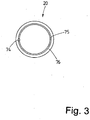
- the data carrier 20 has a passive chip 74, which is designed here as a passive radio frequency identification chip (RFID chip), a coil 75, which is connected to the chip 74 in an electrically conductive manner, and a carrier 76 made of non-conductive Material, for example plastic, which can be designed as a carrier film or carrier body ( Fig. 3 ).
- RFID chip forming the data carrier 20 operates in a frequency range between 800 MHz and 1,000 MHz.
- the RFID chip generates a magnetic field, which is inductively coupled via the antenna 17.
- the antenna 17 has a slot 18 within the electrically conductive license plate body 11, namely in the aluminum sheet for forming the license plate body 11.
- the antenna 17 is thus formed by the license plate body 11 with the slot 18.
- the slot 18 runs in the embodiment of FIG Fig. 1 from an upper edge 16 of the license plate body 11 approximately perpendicular to this upper edge 16 into the license plate body 11. As a result, the slot 18 is open on one side. The slot 18 can also start from any other edge of the license plate body 11. At the end of the slot 18 opposite the open side, an opening 19 is arranged inside the license plate body 11. This opening 19 extends the closed end of the slot 18 located in the license plate body 11.
- the opening 19 corresponds to the shape or base area of the data carrier 20, so that the data carrier 20 can be inserted into the opening 19, namely from the boundary surface 21 of the opening 19 is surrounded, preferably a circumferential gap between the opening 19 and the data carrier 20 remains.
- the data carrier 20 is electrically insulated from its license plate body 11 by its non-conductive carrier 76. In this way, the data carrier 20 is inductively coupled to the antenna 17.
- the antenna 17 formed in the manner described above serves at the label 10 at the same time as an amplifier for the signals of the chip 74, as a result of which the relevant data of the chip 74 can be read out at a relatively large distance from the label 10.
- the identification 10 has on the front side 14 provided with the inscription 23 a coating which is designed as a self-adhesive and preferably reflective film 24.
- the film 24 covers the entire front side 14 of the label 10.
- the slot 18 with the opening 19 and the data carrier 20 are thus completely covered by the film 24.
- the reflective film 24 is provided with a demetallised region 83 where the data carrier 20, the opening 19 and the slot 18 are located, or the layer structure has been changed in this way, that in the area of the data carrier 20, the opening 19 and the slot 18 the reflective film 24 is not conductive.
- the reflective film 24 is thus completely non-conductive in the entire region of the slot 18, including the opening 19.
- the reflective film 24 is also continuously non-conductive, in particular demetallized, in edge regions adjacent to the slot 18 and the opening 19 or the data carrier 20.
- a non-conductive sticker 25 is arranged on a rear side 26 of the license plate body 11.
- this sticker 25 covers at least the area of the slot 18 with the opening 19 and the data carrier 20 arranged therein.
- the sticker 25 can also cover a larger area or can be designed as a self-adhesive film covering the entire rear side 26 of the label 10.
- the data carrier 20, in particular the carrier 76, is approximately as high as the number plate body 11 is thick. This makes it possible to accommodate and fix the data carrier 20 flush between the film 24 applied on the front 14 and the sticker 25 applied on the rear 26 within the opening 19 ( Fig. 2 ).
- the support 76 shown has a round base, in the same way as the opening 19.
- the support 76 and the opening 19 corresponding thereto can also have base surfaces with any other geometrical designs.
- the area of the opening 19 corresponds geometrically to the base area of the data carrier 20, namely its carrier 76.
- the opening 19 is larger than the carrier 76 in the exemplary embodiment shown, as a result of which the carrier 76 is surrounded by a circumferential gap.
- the Fig. 4 shows a label 10, which differs from that of Fig. 1 and 2nd differs only by a changed slot 77.
- This slot 77 has ends closed on both sides.
- the slot 77 extends at a small distance parallel to the lower longitudinal edge of the license plate body 11, specifically in the area of the labeling field 22.
- the straight slot 77 lies between the labeling 23 and the fold 13 on the lower longitudinal edge of the license plate 10.
- the opening 19 is assigned to one end of a slot 77 and is designed to correspond to the base area of the data carrier 20, namely a carrier 76.
- the opening 20 is as in the embodiment of the Fig. 1 and 2nd educated.
- the data carrier 20 corresponds to that in the Fig. 3 disk 20 shown.
- the mark 10 of the Fig. 5 differs from the identifier 10 of the previously described exemplary embodiments only in that the slot 78 has a different course.
- This slot 78 is also closed at both ends, but kinked at right angles, preferably in the middle.
- one half of the slot 78 extends in the region of a longitudinal edge, while the other part of the slot 78 runs parallel to the shorter transverse edge of the label 10.
- a closed end of the slot 78 is again associated with an opening 19 which is designed to correspond to the data carrier 20.
- the opening 19 with the data carrier 20 is located at that end of the angled slot 78 which is assigned to the longitudinal edge of the license plate body 11.
- the opening 19 with the data carrier 20 can also be located at that end of the slot 78 which is assigned to the shorter transverse edge of the license plate body 11.
- the opening 19 corresponds to that of the embodiment of FIG Fig. 1 .
- the data carrier 20 is also designed as in FIG Fig. 3 shown. On the description of the 1 to 3 is referenced.
- the mark 10 of the Fig. 6 differs from the characteristic described above in that the data carrier 20, which is basically designed as in FIG Fig. 3 shown and described, is arranged in a receiving recess 79.
- the receiving trough 79 like the fold 13, is embossed into the license plate body 11 formed from sheet metal, specifically from the front 14 of the license plate body 11, as a result of which the receiving trough 79 on the front 14 of the license plate 10 is open.
- the data carrier 20 can be inserted into the receiving recess 79 from the front 14.
- the depth of the receiving trough 79 is selected such that the upper side of the data carrier 20 facing the front side 14 of the label 10 is approximately flush with the front side 14 of the label 10.
- the receiving trough 79 is assigned to one end of the slot in the license plate body 11. This end of the slot need not have an opening 19; because the opening 19 is replaced in this embodiment by the receiving trough 79.
- the receiving trough 79 can be located at one end of the slot 18, 77 or 78.
- the receiving trough 79 is stamped into the license plate body 11 at the end of the respective slot 18, 77 or 78, as a result of which a bottom wall 80 of the receiving trough 79 has a continuous opening 81 formed by the end of the respective slot 18, 77 or 78.
- This opening 81 is at least smaller in width than the outer dimensions of the carrier 76 of the data carrier 20, as a result of which the data carrier 20 does not fit through the through opening 81 in the bottom wall 80 of the receiving trough 79.
- the receiving trough 79 is embossed into the license plate body 11 after its front side 14 has already been provided with the film 24.
- the data carrier 20 is fastened in the receiving recess 79 open at the top by a non-conductive mass, for example an adhesive 82.
- the adhesive 82 also fills an intermediate space surrounding the data carrier 20 between the outer walls of the carrier 76 and the larger receiving trough 79, so that the receiving trough 79 is completely filled by the data carrier 20 and the adhesive 82 ( Fig. 6 ).
- the film 24 need not be demetallized in the region of the receiving trough 79 and the data carrier 20.
- a label can be glued onto the receiving recess 79 from the front 14 of the label 10.
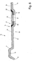
- the Fig. 7 shows a further embodiment of the label 10, which is like the label of the Fig. 6 has a receiving trough 79.
- the receiving trough 79 is formed in exactly the same way as the identifier 10 in FIG Fig. 6 , which is why it is provided with the same reference numbers.
- the bottom wall 80 of the receiving recess 79 also has an opening 81 here, which is formed by one end of a slot 18, 77 or 78.
- Deviating from the embodiment of Fig. 6 is in the embodiment of Fig. 7 the receiving trough 79 is embossed in the license plate body 11 before the film 24 has been glued to the front 14 of the license plate body 11.
- the inside of the receiving trough 79 is not coated with the film 24.
- the data carrier 20 is inserted into the uncoated receiving trough 79.
- electrically non-conductive insulation between the conductive sheet metal of the license plate body 11 and the data carrier 20 is brought about by the carrier 76 formed from non-conductive material.
- the data carrier 20 is also not glued into the receiving trough 79.
- the underside of the data carrier 20 rests on the part of the bottom wall 80 that partially surrounds the opening 81, while the data carrier 20 is held on the top by the film 24, which is located in the Fig. 7 Indicator 10 shown extends over the receiving trough 79, and evenly.
- the film 24 is a reflective film with conductive properties.
- the reflective film 24 in the area of the data carrier 20 or the receiving trough 79 is electrically non-conductive through a demetallized area 83.
- the data carrier 20 arranged in the receiving trough 79 can transmit amplified signals which are at a relatively large distance from the label 10 from a reading device or the like can be received.
- the slots 18, 77 and 78 have a width which corresponds to 1.5 times to 2 times the thickness of the sheet for forming the license plate body 11. Depending on the sheet thickness, the slot can therefore have a width between 1.5 mm and 2.5 mm, preferably about 2 mm.
- the length of the slot is between 100 mm and 200 mm, preferably about 160 mm.
- the diameter of the data carrier 20 is in the range between 6 mm and 10 mm, preferably it is approximately 8 mm.
- the thickness of the data carrier 20, in particular of the carrier 76 can approximately correspond to the plate thickness of the license plate body 11 in the number plate 10.
Description
- Die Erfindung betrifft ein Kennzeichen für ein Fahrzeug gemäß dem Oberbegriff des Anspruchs 1.
- Bei den Kennzeichen gemäß der Erfindung handelt es sich um sogenannte Nummernschilder, die vorn und hinten an der Karosserie oder der Stoßstange eines Fahrzeugs befestigt werden und solche, die auf eine Scheibe des Fahrzeugs geklebt werden, und zwar insbesondere als Zusatzkennzeichen.
- Kennzeichen der genannten Art werden häufig gefälscht oder für fremde Fahrzeuge verwendet. Um das zu verhindern sind Kennzeichen bekannt, welche einen berührungslos auslesbaren Datenträger aufweisen. Dieser enthält relevante Daten des Fahrzeuges, zu dem das Kennzeichen gehört. Das Auslesen dieser Daten erfolgt mittels eines externen Lesegerätes. Der Vergleich der ausgelesenen Daten mit dem Fahrzeug, an dem das Kennzeichen verwendet wird, lässt Rückschlüsse auf Manipulationen zu, insbesondere, wenn das Kennzeichen einem fremden Fahrzeug zugeordnet ist.
- Bisher bekannte Kennzeichen mit berührungslos auslesbaren Datenträgern weisen eine separate Antenne auf. Diese ist mit elektrischen Leitungen an den Datenträger angeschlossen, um die Übertragung der Daten zu ermöglichen. Ein solches Kennzeichen ist aufwändig und störanfällig.
- Aus der gattungsbildenden
EP 1 903 531 A1 geht eine Fahrzeugidentifikationseinrichtung hervor, mit einem Kennzeichenkörper und einem RFID Bauteil, die elektrisch miteinander gekoppelt sind. Das RFID Bauteil weist dabei eine eigene Antenne zum Senden auf, wobei der Kennzeichenkörper als Empfangsantenne dient. Der Kennzeichenkörper kann sowohl eine Antenne zum Senden als auch zum Empfangen bilden. - Aus
WO 2008/020771 A2 undDE 20 2005 018 589 U1 geht ein Kennzeichen mit einer schlitzförmigen Antenne und einem RFID-Chip hervor. - Aus
WO 99/19170 GB 2 429 828 A - Der Erfindung liegt die Aufgabe zugrunde ein vereinfachtes Kennzeichen mit einem Datenträger und einer Antenne zu schaffen.
- Ein Kennzeichen, insbesondere Fahrzeugkennzeichen, zur Lösung dieser Aufgabe weist die Merkmale des Anspruchs 1 auf. Dieses Kennzeichen verfügt über wenigstens einen Datenträger, der ein magnetisches Feld erzeugt und über eine Antenne, die durch den zumindest einen Schlitz aufweisenden Kennzeichenkörper gebildet ist. Der Kennzeichenkörper ist mindestens teilweise aus einem elektrisch leitfähigen Material gebildet, beispielsweise aus Aluminiumblech. Es entsteht so ein Kennzeichen mit einem Transponder aus dem ein magnetisches Feld erzeugenden Datenträger und der Antenne. Der Schlitz im mindestens teilweise leitfähigen Kennzeichenkörper führt zu einer induktiven Einkopplung der Daten des Datenträgers in den als Antenne dienenden Kennzeichenkörper. Der Datenträger ist induktiv an den Schlitz angekoppelt. Der Datenträger weist einen Chip, mindestens eine damit elektrisch leitend verbundene Spule und einen Träger aus einem isolierenden bzw. nichtleitenden Material auf. Die Antenne, insbesondere der Schlitz bzw. der Datenträger, dienen dabei gleichzeitig als Verstärker. Die Daten des Datenträgers sind so ohne zusätzliche Bauteile und auch ohne Anschlüsse des Datenträgers auch aus relativ großer Entfernung aus dem Kennzeichen auslesbar. Außerdem ist der Träger des Datenträgers als Trägerkörper ausgebildet. Der Schlitz weist zur Aufnahme des Trägers mindestens einen Durchbruch auf, wobei der Durchbruch am Ende des Schlitzes aufgeweitet ist.
- Nach einer bevorzugten Ausgestaltung der Erfindung ist es vorgesehen, dass der Datenträger elektrisch isoliert innerhalb des Schlitzes angeordnet ist, und zwar vorzugsweise an einem geschlossenen Ende des Schlitzes. Damit ist der Datenträger im Kennzeichenkörper unterbringbar bzw. integrierbar, ohne dass er zusätzlichen Bauraum erfordert und auch von der Außenseite des Kennzeichens nicht wahrnehmbar ist.
- Es ist bevorzugt vorgesehen, dass der Datenträger, insbesondere die elektrisch leitenden Komponenten desselben, keinen Kontakt, und zwar insbesondere keinen elektrisch leitenden Kontakt, zum Kennzeichenkörper des Kennzeichens aufweisen. Zwischen den leitenden Komponenten des Datenträgers und dem Schlitz im Kennzeichenkörper ist dazu ein umlaufender Spalt oder Zwischenraum gebildet, wodurch eine besonders wirksame, berührungslose Ankopplung des Datenträgers an den elektrisch leitfähigen Kennzeichenträger des Kennzeichens erfolgt. Diese Ankopplung geschieht induktiv durch das vom Datenträger erzeugte magnetische Feld.
- Durch die Anordnung des Datenträgers im Bereich der vom Durchbruch geschaffenen Aufweitung eines Endes des Schlitzes wird ausreichender Raum fürauch größere Datenträger im Kennzeichenkörper geschaffen. Der Datenträger befindet sich dabei innerhalb der Umrisse des Kennzeichenträgers, und zwar ohne hiermit in einen körperlichen bzw. elektrischen Kontakt zu gelangen. Der Datenträger ist im Inneren des Kennzeichens nicht wahrnehmbar, wodurch eine unsichtbare elektrische bzw. elektronische Sicherung des Kennzeichens geschaffen wird.
- Es ist bevorzugt vorgesehen, den Datenträger im Kennzeichen, nämlich im Kennzeichenkörper, zu fixieren. Dazu kommt jedes nicht leitende Mittel zur Fixierung des Datenträgers im Kennzeichen in Betracht, wobei dieses Mittel nicht die ganze Fläche des Kennzeichens überdecken muss. Insbesondere geschieht die Fixierung mittels mindestens einer Beschichtung oder Klebeschicht, die den Kennzeichenkörper wenigstens teilweise überdeckt. Die Lesbarkeit der Daten des Datenträgers wird durch die elektrisch nicht leitende Beschichtung oder Klebeschicht nicht beeinträchtigt. Eventuelle Manipulationen am Datenträger würden zu einer leicht wahrnehmbaren Beschädigung der Beschichtung oder Klebeschicht führen. Bei einer alternativen Ausgestaltung der Erfindung wird der Datenträger durch eine auf der sichtbaren Vorderseite des Kennzeichenkörpers aufgebrachte Reflexfolie im Schlitz bzw. Durchbruch fixiert. Hierbei ist die Reflexfolie mindestens im Bereich des Datenträgers, des Schlitzes und/oder des Durchbruchs demetallisiert und dadurch nichtleitend gemacht.
- Der Datenträger verfügt über einen passiven Radio-Frequency-Identification-Chip (RFID-Chip), womit die Spule elektrisch leitend verbunden ist. Der Träger erleichtert die Fixierung des Datenträgers im Kennzeichenkörper. Vor allem stellt der aus einem Isolator gebildete Träger sicher, dass der Chip und die Spule des Datenträgers gegenüber dem Kennzeichenkörper isoliert im Kennzeichen integrierbar sind, so dass es zu einer induktiven bzw. magnetischen Ankopplung der Signale des Chips an insbesondere den Kennzeichenkörper des Kennzeichens kommt.
- Bevorzugte Ausführungsbeispiele der Erfindung werden nachfolgend anhand der Zeichnung näher erläutert. In dieser zeigen:
- Fig. 1
- ein erfindungsgemäßes Kennzeichen mit einem Kennzeichenträger aus Aluminiumblech und einem integrierten Datenträger,
- Fig. 2
- einen Querschnitt durch das Kennzeichen der
Fig. 1 , - Fig. 3
- den Datenträger in einer Draufsicht,
- Fig. 4
- ein zweites Ausführungsbeispiel eines Kennzeichens in einer Darstellung gemäß der
Fig. 1 , - Fig. 5
- ein drittes Ausführungsbeispiel eines Kennzeichens in einer Darstellung gemäß
Fig. 1 , - Fig. 6
- ein viertes Ausführungsbeispiel eines Kennzeichens in einer Darstellung gemäß
Fig. 2 , und - Fig. 7
- ein fünftes Ausführungsbeispiel eines Kennzeichens in einer Darstellung gemäß
Fig. 2 . - Die in den Figuren gezeigten Kennzeichen 10 weisen einen plattenartigen Kennzeichenkörper 11 aus Aluminiumblech auf. Das Kennzeichen 10 ist rechteckig ausgebildet, wobei seine Abmaße denen eines üblichen Fahrzeugkennzeichens entsprechen. Der Kennzeichenkörper 11 ist an seinem Rand 12 mit einem umlaufenden Falz 13 versehen. Dieser Falz 13 wird mittels eines Umformverfahrens, vorzugsweise durch Prägen, in den Kennzeichenkörper 11 eingebracht.
- Kennzeichen 10 dieser Art, sogenannte Nummernschilder, werden üblicherweise vorn und hinten am Fahrzeug, und zwar an der Karosserie und/oder der Stoßstange angebracht. Dazu weist das Kennzeichen 10 mehrere Befestigungslöcher 15 auf.
- Innerhalb der durch den Falz 13 begrenzten Vorderseite 14 verfügt der Kennzeichenkörper 11 über ein Beschriftungsfeld 22. Auf dem Beschriftungsfeld 22 befindet sich eine Beschriftung 23 des Kennzeichens 10. Die Einbringung der Beschriftung 23 in das Beschriftungsfeld 22 erfolgt vorzugsweise ebenfalls durch Prägen.
- Die Beschriftung kann beliebig sein, ist nämlich nicht auf das in den
Fig. 1 ,4 und5 gezeigte Beispiel beschränkt. Es ist insbesondere jede Kombination von Buchstaben, Zahlen und Zeichen möglich, um die Beschriftung 23 zu bilden. - Das Kennzeichen 10 weist einen Transponder auf. Der Transponder verfügt über eine Antenne 17 und einen passiven Datenträger 20. Die gespeicherten Daten des Datenträgers 20 sind über die Antenne 17 berührungslos auslesbar. Der Datenträger 20 verfügt über ausgewählte Daten des Fahrzeugs, zu dem das Kennzeichen 10 gehört. Der Datenträger 20 verfügt über einen passiven Chip 74, der hier als ein passiver Radio-Frequency-Identification-Chip (RFID-Chip) ausgebildet ist, eine Spule 75, die elektrisch leitend an den Chip 74 angeschlossen ist, und einen Träger 76 aus nichtleitendem Material, zum Beispiel Kunststoff, der als Trägerfolie oder Trägerkörper ausgebildet sein kann (
Fig. 3 ). Der den Datenträger 20 bildende passive RFID-Chip arbeitet in einem Frequenzbereich zwischen 800 MHz und 1.000 MHZ. Der RFID-Chip erzeugt ein magnetisches Feld, das über die Antenne 17 induktiv gekoppelt wird. - Die Antenne 17 verfügt über einen Schlitz 18 innerhalb des elektrisch leitfähigen Kennzeichenkörpers 11, nämlich im Aluminiumblech zur Bildung des Kennzeichenkörpers 11. Die Antenne 17 wird somit gebildet vom Kennzeichenkörper 11 mit dem Schlitz 18.
- Der Schlitz 18 verläuft im Ausführungsbeispiel der
Fig. 1 von einem oberen Rand 16 des Kennzeichenkörpers 11 aus etwa senkrecht zu diesem oberen Rand 16 in den Kennzeichenkörper 11 hinein. Dadurch ist der Schlitz 18 an einer Seite offen. Der Schlitz 18 kann aber auch von jedem anderen Rand des Kennzeichenkörpers 11 ausgehen. An dem der offenen Seite gegenüberliegenden Ende des Schlitzes 18 ist innerhalb des Kennzeichenkörpers 11 ein Durchbruch 19 angeordnet. Dieser Durchbruch 19 erweitert das im Kennzeichenkörper 11 liegende, geschlossene Ende des Schlitzes 18. Der Durchbruch 19 korrespondiert dabei mit der Gestalt bzw. Grundfläche des Datenträgers 20, sodass der Datenträger 20 in den Durchbruch 19 einsetzbar ist, nämlich von der Begrenzungsfläche 21 des Durchbruchs 19 umgeben ist, vorzugsweise ein umlaufender Spalt zwischen dem Durchbruch 19 und dem Datenträger 20 verbleibt. Der Datenträger 20 ist von seinem nichtleitenden Träger 76 vom Kennzeichenkörper 11 elektrisch isoliert. Auf diese Weise kommt es zur induktiven Ankopplung des Datenträgers 20 an die Antenne 17. - Die in vorstehend beschriebener Weise gebildete Antenne 17 dient beim Kennzeichen 10 gleichzeitig als Verstärker für die Signale des Chips 74, wodurch die relevanten Daten des Chips 74 mit relativ großem Abstand vom Kennzeichen 10 ausgelesen werden können.
- Das Kennzeichen 10 weist auf der mit der Beschriftung 23 versehenen Vorderseite 14 eine als selbstklebende und vorzugsweise reflektierende Folie 24 ausgeführte Beschichtung auf. Die Folie 24 überdeckt die gesamte Vorderseite 14 des Kennzeichens 10. Damit sind auch der Schlitz 18 mit dem Durchbruch 19 und der Datenträger 20 vollständig von der Folie 24 überdeckt. Im Falle einer reflektierenden Folie 24 mit metallisch leitenden Bestandteilen ist es vorgesehen, dass die reflektierende Folie 24 dort, wo sich der Datenträger 20, der Durchbruch 19 und der Schlitz 18 befinden, mit einem demetallisierten Bereich 83 versehen ist oder im Schichtenaufbau so verändert wurde, dass im Bereich des Datenträgers 20, des Durchbruchs 19 und des Schlitzes 18 die reflektierende Folie 24 nicht leitend ist. Somit ist die reflektierende Folie 24 im gesamten Bereich des Schlitzes 18 einschließlich des Durchbruchs 19 vollständig nicht leitend. Bevorzugt ist die reflektierende Folie 24 auch in an den Schlitz 18 und den Durchbruch 19 bzw. den Datenträger 20 angrenzenden Randbereichen durchgehend elektrisch nicht leitend ausgebildet, insbesondere demetallisiert.
- Auf einer Rückseite 26 des Kennzeichenkörpers 11 ist ein nicht leitender Aufkleber 25 angeordnet. Im gezeigten Ausführungsbeispiel (
Fig. 2 ) überdeckt dieser Aufkleber 25 mindestens den Bereich des Schlitzes 18 mit dem Durchbruch 19 und den darin angeordneten Datenträger 20. Der Aufkleber 25 kann jedoch auch einen größeren Bereich überdecken, oder als eine die gesamte Rückseite 26 des Kennzeichens 10 überdeckende selbstklebende Folie ausgebildet sein. - Der Datenträger 20, insbesondere der Träger 76, ist etwa so hoch, wie der Kennzeichenkörper 11 dick ist. Hierdurch ist es möglich, den Datenträger 20 zwischen der auf der Vorderseite 14 aufgebrachten Folie 24 und dem auf der Rückseite 26 aufgebrachten Aufkleber 25 innerhalb des Durchbruchs 19 flächenbündig unterzubringen und zu fixieren (
Fig. 2 ). - Der in der
Fig. 3 gezeigte Träger 76 weist eine runde Grundfläche auf, und zwar ebenso wie der Durchbruch 19. Der Träger 76 und der dazu korrespondierende Durchbruch 19 können aber auch Grundflächen mit beliebigen anderen geometrischen Gestaltungen aufweisen. Die Fläche des Durchbruchs 19 stimmt geometrisch mit der Grundfläche des Datenträgers 20, nämlich seines Trägers 76, überein. Der Durchbruch 19 ist im gezeigten Ausführungsbeispiel größer als der Träger 76, wodurch der Träger 76 von einem umlaufenden Spalt umgeben ist. - Die
Fig. 4 zeigt ein Kennzeichen 10, das sich von demjenigen derFig. 1 und2 nur durch einen geänderten Schlitz 77 unterscheidet. Dieser Schlitz 77 hat beidseitig geschlossene Enden. Der Schlitz 77 erstreckt sich mit geringem Abstand parallel zum unteren Längsrand des Kennzeichenkörpers 11, und zwar im Bereich des Beschriftungsfelds 22. Im gezeigten Ausführungsbeispiel liegt der geradlinige Schlitz 77 zwischen der Beschriftung 23 und der Falz 13 am unteren Längsrand des Kennzeichens 10. - Einem Ende eines Schlitzes 77 ist der Durchbruch 19 zugeordnet, der korrespondierend zur Grundfläche des Datenträgers 20, nämlich eines Trägers 76, ausgebildet ist. Der Durchbruch 20 ist wie beim Ausführungsbeispiel der
Fig. 1 und2 ausgebildet. Der Datenträger 20 entspricht dem in derFig. 3 gezeigten Datenträger 20. - Das Kennzeichen 10 der
Fig. 5 unterscheidet sich von dem Kennzeichen 10 der zuvor beschriebenen Ausführungsbeispiele nur dadurch, dass der Schlitz 78 einen anderen Verlauf aufweist. Dieser Schlitz 78 ist auch an beiden Enden geschlossen, aber rechtwinklig abgeknickt, und zwar vorzugsweise mittig. Dadurch erstreckt sich eine Hälfte des Schlitzes 78 im Bereich eines Längsrands, während der andere Teil des Schlitzes 78 parallel zum kürzeren Querrand des Kennzeichens 10 verläuft. Einem geschlossenen Ende des Schlitzes 78 ist wieder ein Durchbruch 19 zugeordnet, der korrespondierend zum Datenträger 20 ausgebildet ist. Beim gezeigten Ausführungsbeispiel befindet sich der Durchbruch 19 mit dem Datenträger 20 an demjenigen Ende des abgewinkelten Schlitzes 78, das dem Längsrand des Kennzeichenkörpers 11 zugeordnet ist. Der Durchbruch 19 mit dem Datenträger 20 kann sich aber auch an demjenigen Ende des Schlitzes 78 befinden, der dem kürzeren Querrand des Kennzeichenkörpers 11 zugeordnet ist. Der Durchbruch 19 entspricht demjenigen des Ausführungsbeispiels derFig. 1 . Der Datenträger 20 ist auch so ausgebildet, wie in derFig. 3 dargestellt. Auf die Beschreibung derFig. 1 bis 3 wird Bezug genommen. - Das Kennzeichen 10 der
Fig. 6 unterscheidet sich vom zuvor beschriebenen Kennzeichen dadurch, dass der Datenträger 20, der grundsätzlich so ausgebildet ist, wie in derFig. 3 dargestellt und beschrieben, in einer Aufnahmemulde 79 angeordnet ist. Die Aufnahmemulde 79 ist wie die Falz 13 in den aus Blech gebildeten Kennzeichenkörper 11 eingeprägt, und zwar von der Vorderseite 14 des Kennzeichenkörpers 11 her, wodurch die Aufnahmemulde 79 an der Vorderseite 14 des Kennzeichens 10 offen ist. Dadurch ist der Datenträger 20 von der Vorderseite 14 her in die Aufnahmemulde 79 einsetzbar. Die Tiefe der Aufnahmemulde 79 ist so gewählt, dass die zur Vorderseite 14 des Kennzeichens 10 weisende Oberseite des Datenträgers 20 etwa bündig mit der Vorderseite 14 des Kennzeichens 10 abschließt. - Die Aufnahmemulde 79 ist einem Ende des Schlitzes im Kennzeichenkörper 11 zugeordnet. Dieses Ende des Schlitzes braucht keinen Durchbruch 19 aufzuweisen; denn der Durchbruch 19 wird bei diesem Ausführungsbeispiel durch die Aufnahmemulde 79 ersetzt. Die Aufnahmemulde 79 kann sich an einem Ende des Schlitzes 18, 77 oder 78 befinden. Die Aufnahmemulde 79 ist am Ende des jeweiligen Schlitzes 18, 77 oder 78 in den Kennzeichenkörper 11 eingeprägt, wodurch eine Bodenwandung 80 der Aufnahmemulde 79 eine vom Ende des jeweiligen Schlitzes 18, 77 oder 78 gebildete durchgehende Öffnung 81 aufweist. Diese Öffnung 81 ist mindestens in der Breite kleiner als die Außenabmessungen des Trägers 76 des Datenträgers 20, wodurch der Datenträger 20 nicht durch die durchgehende Öffnung 81 in der Bodenwandung 80 der Aufnahmemulde 79 hindurchpasst.
- Im gezeigten Ausführungsbeispiel ist die Aufnahmemulde 79 in den Kennzeichenkörper 11 eingeprägt, nachdem seine Vorderseite 14 bereits mit der Folie 24 versehen ist. Die Folie 24, bei der es sich um eine Reflexfolie handeln kann, erstreckt sich dadurch über die Bodenwandung 80 der Aufnahmemulde 79 hinweg. In diesem Falle ist der Datenträger 20 in der oben offenen Aufnahmemulde 79 durch eine nicht leitende Masse, beispielsweise einen Kleber 82, befestigt. Der Kleber 82 füllt im gezeigten Ausführungsbeispiel auch einen den Datenträger 20 ringsherum umgebenden Zwischenraum zwischen den Außenwandungen des Trägers 76 und der demgegenüber größeren Aufnahmemulde 79 aus, so dass durch den Datenträger 20 und den Kleber 82 die Aufnahmemulde 79 völlig ausgefüllt ist (
Fig. 6 ). Beim hier gezeigten Ausführungsbeispiel braucht die Folie 24 im Bereich der Aufnahmemulde 79 und des Datenträgers 20 nicht demetallisiert zu sein. Auf die Aufnahmemulde 79 kann von der Vorderseite 14 des Kennzeichens 10 ein Label aufgeklebt sein. - Die
Fig. 7 zeigt ein weiteres Ausführungsbeispiel des Kennzeichens 10, was wie das Kennzeichen derFig. 6 eine Aufnahmemulde 79 aufweist. Die Aufnahmemulde 79 ist genauso ausgebildet wie beim Kennzeichen 10 derFig. 6 , weswegen sie mit gleichen Bezugsziffern versehen ist. Insbesondere weist die Bodenwandung 80 der Aufnahmemulde 79 auch hier eine Öffnung 81 auf, die von einem Ende eines Schlitzes 18, 77 oder 78 gebildet ist. - Abweichend vom Ausführungsbeispiel der
Fig. 6 ist beim Ausführungsbeispiel derFig. 7 die Aufnahmemulde 79 im Kennzeichenkörper 11 eingeprägt, bevor die Folie 24 auf die Vorderseite 14 des Kennzeichenkörpers 11 aufgeklebt worden ist. Dadurch ist die Innenseite der Aufnahmemulde 79 nicht mit der Folie 24 beschichtet. Der Datenträger 20 ist vielmehr in die unbeschichtete Aufnahmemulde 79 eingesetzt. Dabei kommt eine elektrisch nichtleitende Isolierung zwischen dem leitenden Blech des Kennzeichenkörpers 11 und dem Datenträger 20 zustande durch den aus nicht leitendem Material gebildeten Träger 76. Der Datenträger 20 ist auch nicht in der Aufnahmemulde 79 festgeklebt. Vielmehr liegt der Datenträger 20 mit der Unterseite auf dem die Öffnung 81 teilweise umgebenden Teil der Bodenwandung 80 auf, während der Datenträger 20 auf der Oberseite gehalten ist durch die Folie 24, die sich beim in derFig. 7 gezeigten Kennzeichen 10 über die Aufnahmemulde 79 hinweg erstreckt, und zwar ebenflächig. Im gezeigten Ausführungsbeispiel handelt es sich bei der Folie 24 um eine Reflexfolie mit leitenden Eigenschaften. Deswegen ist die Reflexfolie 24 im Bereich des Datenträgers 20 bzw. der Aufnahmemulde 79 elektrisch nichtleitend durch einen demetallisierten Bereich 83. Dadurch kann der in der Aufnahmemulde 79 angeordnete Datenträger 20 verstärkte Signale absenden, die mit verhältnismäßig großem Abstand vom Kennzeichen 10 von einem Lesegerät oder dergleichen empfangen werden können. - Die Schlitze 18, 77 bzw. 78 weisen eine Breite auf, die der 1,5-fachen bis 2-fachen Dicke des Blechs zur Bildung des Kennzeichenkörpers 11 entspricht. Je nach Blechdicke kann deshalb der Schlitz eine Breite zwischen 1,5 mm und 2,5 mm, vorzugsweise etwa 2 mm, aufweisen. Die Länge des Schlitzes beträgt zwischen 100 mm und 200 mm, vorzugsweise etwa 160 mm. Der Durchmesser des Datenträgers 20 liegt im Bereich zwischen 6 mm und 10 mm, vorzugsweise beträgt er etwa 8 mm. Die Dicke des Datenträgers 20, insbesondere des Trägers 76, kann beim Kennzeichen 10 etwa der Blechdicke des Kennzeichenkörpers 11 entsprechen.
Claims (6)
- Kennzeichen für ein Fahrzeug mit einem flächigen, zumindest teilweise elektrisch leitenden Kennzeichenkörper (11), der wenigstens ein Beschriftungsfeld (22) aufweist, und mit mindestens einer Beschriftung (23), die dem Beschriftungsfeld (22) des Kennzeichenkörpers (11) zugeordnet ist, wobei dem Kennzeichenkörper (11) ein berührungslos auslesbarer Datenträger (20) und eine durch zumindest einen Schlitz (18, 77, 78) im Kennzeichenkörper (11) gebildete Antenne (17) zugeordnet sind und der Datenträger (20) ein ein magnetisches Feld erzeugender Datenträger (20) ist, wobei der Datenträger (20) induktiv an den Schlitz (18, 77, 78) angekoppelt ist, und wobei der Datenträger (20) einen passiven RFID-Chip (74), mindestens eine damit elektrisch leitend verbundene Spule (75) und einen Träger (76) aus einem isolierenden bzw. nichtleitenden Material aufweist und der Schlitz (18, 77, 78) bzw. der Datenträger (20) gleichzeitig als Verstärker dienen, dadurch gekennzeichnet, dass der Träger (76) des Datenträgers (20) als Trägerkörper ausgebildet ist und der Schlitz (18, 77, 78) zur Aufnahme des Trägers (76) mindestens einen Durchbruch (19) aufweist, wobei durch den Durchbruch (19) ein Ende des Schlitzes (18, 77, 78) aufgeweitet ist.
- Kennzeichen nach Anspruch 1, dadurch gekennzeichnet, dass der Datenträger (20) elektrisch isoliert dem Schlitz (18, 77, 78) zugeordnet ist, insbesondere im Bereich eines Endes des Schlitzes (18, 77, 78).
- Kennzeichen nach Anspruch 1 oder 2, dadurch gekennzeichnet, dass der Datenträger (20) isoliert innerhalb des Schlitzes (18, 77, 78) oder über dem Schlitz (18, 77, 78) angeordnet ist, vorzugsweise elektrisch leitende Bestandteile des Datenträgers (20) von den Begreniungsflächen (21) des Schlitzes (18, 77, 78) beabstandet sind.
- Kennzeichen nach einem der vorhergehenden Ansprüche, dadurch gekennzeichnet, dass der Durchbruch (19) den Schlitz (18, 77, 78) im Bereich seines geschlossenen Endes vergrößert.
- Kennzeichen nach einem oder mehreren der vorhergehenden Ansprüche, dadurch gekennzeichnet, dass der Datenträger (20) im Kennzeichenkörper (11) eingebettet ist, insbesondere im Schlitz (18, 77, 78) bzw. im Durchbruch (19) fixiert ist, vorzugsweise von mindestens einer Beschichtung (24) auf dem Kennzeichenkörper (11).
- Kennzeichen nach Anspruch 5, dadurch gekennzeichnet, dass zumindest eine sichtbare Beschichtung (24) als eine insbesondere selbstklebende Reflexfolie ausgebildet ist, die vorzugsweise im Bereich des Datenträgers (20) bzw. des Durchbruchs (19) und/ oder des Schlitzes (18, 77, 78) so ausgebildet ist, dass sie keine leitenden Bestandteile aufweist.
Priority Applications (4)
| Application Number | Priority Date | Filing Date | Title |
|---|---|---|---|
| RS20161074A RS55402B2 (sr) | 2008-11-04 | 2009-11-04 | Identifikacione tablice za vozila |
| SI200931563T SI2344364T2 (sl) | 2008-11-04 | 2009-11-04 | Identifikacijske tablice za vozilo |
| PL09749017T PL2344364T5 (pl) | 2008-11-04 | 2009-11-04 | Tablica rejestracyjna pojazdu |
| HRP20161576TT HRP20161576T4 (hr) | 2008-11-04 | 2016-11-25 | Registarske tablice za vozilo |
Applications Claiming Priority (3)
| Application Number | Priority Date | Filing Date | Title |
|---|---|---|---|
| DE102008055772 | 2008-11-04 | ||
| DE102009033559A DE102009033559A1 (de) | 2008-11-04 | 2009-07-16 | Kennzeichen für ein Fahrzeug |
| PCT/EP2009/007902 WO2010051980A1 (de) | 2008-11-04 | 2009-11-04 | Kennzeichen für ein fahrzeug |
Publications (3)
| Publication Number | Publication Date |
|---|---|
| EP2344364A1 EP2344364A1 (de) | 2011-07-20 |
| EP2344364B1 EP2344364B1 (de) | 2016-09-07 |
| EP2344364B2 true EP2344364B2 (de) | 2020-07-08 |
Family
ID=42063165
Family Applications (1)
| Application Number | Title | Priority Date | Filing Date |
|---|---|---|---|
| EP09749017.1A Active EP2344364B2 (de) | 2008-11-04 | 2009-11-04 | Kennzeichen für ein fahrzeug |
Country Status (22)
| Country | Link |
|---|---|
| US (2) | US8737915B2 (de) |
| EP (1) | EP2344364B2 (de) |
| JP (1) | JP5633076B2 (de) |
| KR (1) | KR101681075B1 (de) |
| AU (1) | AU2009313096B2 (de) |
| BR (1) | BRPI0921642B1 (de) |
| CA (1) | CA2742284C (de) |
| DE (1) | DE102009033559A1 (de) |
| DK (1) | DK2344364T4 (de) |
| ES (1) | ES2601526T5 (de) |
| HR (1) | HRP20161576T4 (de) |
| HU (1) | HUE030918T2 (de) |
| LT (1) | LT2344364T (de) |
| MX (1) | MX2011004652A (de) |
| MY (1) | MY155795A (de) |
| PL (1) | PL2344364T5 (de) |
| PT (1) | PT2344364T (de) |
| RS (1) | RS55402B2 (de) |
| RU (1) | RU2526871C2 (de) |
| SI (1) | SI2344364T2 (de) |
| WO (1) | WO2010051980A1 (de) |
| ZA (1) | ZA201103137B (de) |
Families Citing this family (34)
| Publication number | Priority date | Publication date | Assignee | Title |
|---|---|---|---|---|
| MX2009006781A (es) | 2006-12-21 | 2010-01-15 | Neology Inc | Sistemas y métodos para una placa de metal habilitada con identificación por radio frecuencia. |
| CN102897112A (zh) * | 2011-07-27 | 2013-01-30 | 众睿科技有限公司 | 车牌装置及车牌制造方法 |
| JP2013152600A (ja) * | 2012-01-25 | 2013-08-08 | Hitachi Chemical Co Ltd | Rfidタグシステム及びrfidパッケージ |
| JPWO2013115216A1 (ja) * | 2012-02-02 | 2015-05-11 | 日本カーバイド工業株式会社 | 標示板 |
| FR2988349B1 (fr) * | 2012-03-26 | 2014-05-09 | Novatec | Plaque mineralogique unique et non duplicable, procede de fabrication d'une telle plaque et procede d'authentification d'une plaque mineralogique |
| DE102012106594A1 (de) * | 2012-07-20 | 2014-01-23 | J.H. Tönnjes E.A.S.T. GmbH & Co. KG | Fahrzeugidentifikationsmittel |
| US11341389B2 (en) | 2013-01-18 | 2022-05-24 | Amatech Group Limited | Manufacturing metal inlays for dual interface metal cards |
| US11928537B2 (en) | 2013-01-18 | 2024-03-12 | Amatech Group Limited | Manufacturing metal inlays for dual interface metal cards |
| GB2516305A (en) * | 2013-07-19 | 2015-01-21 | Nokia Corp | Apparatus and methods for wireless communication |
| PT107661A (pt) * | 2014-05-27 | 2015-11-27 | Porta Saber Comércio E Serviços De Consultoria Unipessoal Lda | Chapa de matrícula para veículos automóveis com dispositivo de identificação de rádio frequência (rfid) |
| US11514288B2 (en) * | 2014-08-10 | 2022-11-29 | Amatech Group Limited | Contactless metal card constructions |
| DE102014012291A1 (de) * | 2014-08-22 | 2016-02-25 | Tönnjes Isi Patent Holding Gmbh | Kennzeichen für ein Fahrzeug |
| WO2016164644A1 (en) | 2015-04-07 | 2016-10-13 | Neology, Inc. | Radio frequency identification tag in a license plate |
| CA2983349C (en) * | 2015-04-22 | 2022-04-19 | Strada Sign Supply Inc. | Compliance method and system for traffic control devices |
| EA027092B1 (ru) * | 2015-07-01 | 2017-06-30 | Владимир Олегович Золотарев | Держатель для таблички для маркировки транспортных средств, перевозящих опасные грузы |
| GB2541657B (en) | 2015-08-24 | 2019-02-06 | Q Free Asa | Vehicle license plate tamper detection system |
| DE102016118913A1 (de) | 2016-10-05 | 2018-04-05 | Erich Utsch Ag | Kennzeichen für ein Kraftfahrzeug sowie ein Verfahren zur Herstellung eines Kennzeichens für ein Kraftfahrzeug |
| RU185008U1 (ru) * | 2016-12-07 | 2018-11-16 | Российская Федерация, от имени которой выступает Федеральное государственное казенное учреждение "Войсковая часть 68240" | Устройство для бесконтактной регистрации и идентификации |
| EP3565737B1 (de) * | 2017-01-05 | 2022-03-09 | Revivermx, Inc. | Digitales kennzeichenschildsystem |
| DE102017000599A1 (de) | 2017-01-20 | 2018-07-26 | KATHREIN Sachsen GmbH | UHF RFID-Transponder |
| KR101969139B1 (ko) * | 2017-02-13 | 2019-04-16 | 주식회사 티모넷 | 스마트 차량 번호판 |
| US20190058248A1 (en) * | 2017-08-18 | 2019-02-21 | Revivermx, Inc. | Antenna System for a Digital License Plate |
| DE102018106432A1 (de) | 2018-03-20 | 2019-09-26 | Erich Utsch Ag | Anordnung aus einem Schild und einem das Schild tragenden Schildträger |
| DE102018002585A1 (de) * | 2018-03-28 | 2019-10-02 | Tönnjes Isi Patent Holding Gmbh | Fahrzeugidentifikationsmittel |
| DE102018007540A1 (de) * | 2018-06-15 | 2019-12-19 | J.H. Tönnjes Gmbh | Verfahren und Vorrichtung zum Ausstatten eines Kennzeichens, vorzugsweise eines Kraftfahrzeug-Kennzeichens, mit einem Datenträger und ein Kennzeichen |
| DE102018005440A1 (de) * | 2018-07-11 | 2020-01-16 | Tönnjes Isi Patent Holding Gmbh | Kennzeichen für ein Fahrzeug und Verfahren zur Herstellung eines Kennzeichens für ein Fahrzeug |
| PL235167B1 (pl) * | 2018-08-03 | 2020-06-01 | Utal Spolka Z Ograniczona Odpowiedzialnoscia | Tablica informacyjna zwłaszcza rejestracyjna |
| DE102018007679A1 (de) * | 2018-09-28 | 2020-04-02 | Tönnjes Isi Patent Holding Gmbh | Kennzeichen für ein Fahrzeug |
| DE102019002722A1 (de) * | 2019-04-15 | 2020-10-15 | Tönnjes Isi Patent Holding Gmbh | Kennzeichen für ein Fahrzeug und Verfahren zur Herstellung eines Kennzeichens für ein Fahrzeug |
| US20210081743A1 (en) | 2019-08-12 | 2021-03-18 | Federal Card Services, LLC | Dual interface metal cards and methods of manufacturing |
| US11113593B2 (en) | 2019-08-15 | 2021-09-07 | Federal Card Services; LLC | Contactless metal cards with fingerprint sensor and display |
| US20210049431A1 (en) | 2019-08-14 | 2021-02-18 | Federal Card Services, LLC | Metal-containing dual interface smartcards |
| US11341385B2 (en) | 2019-11-16 | 2022-05-24 | Federal Card Services, LLC | RFID enabled metal transaction card with shaped opening and shaped slit |
| WO2023034642A1 (en) | 2021-09-06 | 2023-03-09 | Metaland Llc | Encapsulating a metal inlay with thermosetting resin and method for making a metal transaction card |
Citations (5)
| Publication number | Priority date | Publication date | Assignee | Title |
|---|---|---|---|---|
| WO2006028707A1 (en) † | 2004-09-01 | 2006-03-16 | Avery Dennison Corporation | Rfid device with magnetic coupling |
| WO2006128448A1 (de) † | 2005-06-01 | 2006-12-07 | Hardy Zissel | Anordnung mit transponder und metallischem element |
| WO2008079902A1 (en) † | 2006-12-21 | 2008-07-03 | Neology, Inc. | Systems and methods for a rfid enabled metal license plate |
| DE102006062308A1 (de) † | 2006-12-27 | 2008-07-17 | ASTRA Gesellschaft für Asset Management mbH & Co. KG | Passives Detektierplättchen |
| DE102007059168A1 (de) † | 2007-12-06 | 2009-06-10 | Schmidt, Werner, Dr.-Ing. habil. | Kommunikationsmodul mit Schlitzantenne |
Family Cites Families (14)
| Publication number | Priority date | Publication date | Assignee | Title |
|---|---|---|---|---|
| US5621571A (en) * | 1994-02-14 | 1997-04-15 | Minnesota Mining And Manufacturing Company | Integrated retroreflective electronic display |
| JPH1125245A (ja) * | 1997-06-27 | 1999-01-29 | Toshiba Chem Corp | 非接触データキャリアパッケージ |
| ES2200388T3 (es) * | 1997-10-14 | 2004-03-01 | Siemens Aktiengesellschaft | Placa de matricula de vehiculos con soporte de datos electronicos legible sin contacto y procedimiento de fabricacion. |
| JP4624536B2 (ja) * | 2000-04-04 | 2011-02-02 | 大日本印刷株式会社 | 非接触式データキャリア装置 |
| RU2185663C1 (ru) * | 2001-07-18 | 2002-07-20 | Закрытое акционерное общество "Энергет и Ко" | Система электронной идентификации автотранспортных средств (варианты) |
| US6894615B2 (en) * | 2001-10-09 | 2005-05-17 | 3M Innovative Properties Company | Article with retroreflective and radio frequency-responsive features |
| US6758405B2 (en) * | 2001-12-19 | 2004-07-06 | 3M Innovative Properties Company | Article with retroreflective and radio frequency-responsive features |
| JP2003331250A (ja) * | 2002-03-05 | 2003-11-21 | Mitsubishi Materials Corp | Rfid付小円板 |
| JP4541246B2 (ja) * | 2004-12-24 | 2010-09-08 | トッパン・フォームズ株式会社 | 非接触icモジュール |
| DE202005018589U1 (de) | 2005-11-29 | 2007-04-12 | Zissel Hardy | Kennzeichnungsblech für Kraftfahrzeuge mit Antenne |
| GB0518000D0 (en) * | 2005-09-03 | 2005-10-12 | Plastisign Ltd | System of obtaining information about a vehicle using radio frequency identification |
| US7463150B2 (en) * | 2005-10-28 | 2008-12-09 | 3M Innovative Properties Company | Vehicle identification tag and methods of verifying the validity of a vehicle identification tag |
| NZ549173A (en) * | 2006-08-15 | 2007-06-29 | Times 7 Holdings Ltd | Licence plate with integrated antenna |
| NL1032542C2 (nl) * | 2006-09-20 | 2008-03-21 | Knieriem B V J | Voertuigidentificatie. |
-
2009
- 2009-07-16 DE DE102009033559A patent/DE102009033559A1/de not_active Withdrawn
- 2009-11-04 JP JP2011533624A patent/JP5633076B2/ja active Active
- 2009-11-04 MX MX2011004652A patent/MX2011004652A/es active IP Right Grant
- 2009-11-04 WO PCT/EP2009/007902 patent/WO2010051980A1/de active Application Filing
- 2009-11-04 CA CA2742284A patent/CA2742284C/en active Active
- 2009-11-04 RU RU2011122207/11A patent/RU2526871C2/ru active
- 2009-11-04 PT PT97490171T patent/PT2344364T/pt unknown
- 2009-11-04 PL PL09749017T patent/PL2344364T5/pl unknown
- 2009-11-04 ES ES09749017T patent/ES2601526T5/es active Active
- 2009-11-04 HU HUE09749017A patent/HUE030918T2/en unknown
- 2009-11-04 BR BRPI0921642-1A patent/BRPI0921642B1/pt active IP Right Grant
- 2009-11-04 US US13/125,509 patent/US8737915B2/en active Active
- 2009-11-04 KR KR1020117011915A patent/KR101681075B1/ko active IP Right Grant
- 2009-11-04 LT LTEP09749017.1T patent/LT2344364T/lt unknown
- 2009-11-04 RS RS20161074A patent/RS55402B2/sr unknown
- 2009-11-04 EP EP09749017.1A patent/EP2344364B2/de active Active
- 2009-11-04 DK DK09749017.1T patent/DK2344364T4/da active
- 2009-11-04 SI SI200931563T patent/SI2344364T2/sl unknown
- 2009-11-04 MY MYPI2011001866A patent/MY155795A/en unknown
- 2009-11-04 AU AU2009313096A patent/AU2009313096B2/en active Active
-
2011
- 2011-04-28 ZA ZA2011/03137A patent/ZA201103137B/en unknown
-
2014
- 2014-04-10 US US14/249,413 patent/US20140217182A1/en not_active Abandoned
-
2016
- 2016-11-25 HR HRP20161576TT patent/HRP20161576T4/hr unknown
Patent Citations (5)
| Publication number | Priority date | Publication date | Assignee | Title |
|---|---|---|---|---|
| WO2006028707A1 (en) † | 2004-09-01 | 2006-03-16 | Avery Dennison Corporation | Rfid device with magnetic coupling |
| WO2006128448A1 (de) † | 2005-06-01 | 2006-12-07 | Hardy Zissel | Anordnung mit transponder und metallischem element |
| WO2008079902A1 (en) † | 2006-12-21 | 2008-07-03 | Neology, Inc. | Systems and methods for a rfid enabled metal license plate |
| DE102006062308A1 (de) † | 2006-12-27 | 2008-07-17 | ASTRA Gesellschaft für Asset Management mbH & Co. KG | Passives Detektierplättchen |
| DE102007059168A1 (de) † | 2007-12-06 | 2009-06-10 | Schmidt, Werner, Dr.-Ing. habil. | Kommunikationsmodul mit Schlitzantenne |
Also Published As
Similar Documents
| Publication | Publication Date | Title |
|---|---|---|
| EP2344364B2 (de) | Kennzeichen für ein fahrzeug | |
| EP3776359B1 (de) | Fahrzeugidentifikationsmittel | |
| EP3183140A1 (de) | Kennzeichen für ein fahrzeug | |
| DE19710514C2 (de) | Steckkarte für elektronische Geräte | |
| WO2020064473A1 (de) | Kennzeichen für ein fahrzeug | |
| WO2009018922A1 (de) | Warenverpackung mit deckfolie | |
| EP1630730B1 (de) | Transponder | |
| DE102005017451A1 (de) | Türgriff für Kraftfahrzeuge mit einem kapazitiven Näherungssensor | |
| AT514156B1 (de) | Getränkedose | |
| EP3820742B1 (de) | Kennzeichen für ein fahrzeug und verfahren zur herstellung eines kennzeichens für ein fahrzeug | |
| EP2158566B1 (de) | Transpondersystem | |
| EP2027762B1 (de) | Elektrische einrichtung mit abschirmung | |
| EP1843281A1 (de) | Datenträger-/Sendevorrichtung und Verfahren zur Herstellung einer Datenträger-/Sendevorrichtung | |
| EP3956179A1 (de) | Kennzeichen für ein fahrzeug und verfahren zur herstellung eines kennzeichens für ein fahrzeug | |
| EP2618425A1 (de) | Antennenabdeckung | |
| DE102016219748A1 (de) | Sensorvorrichtung für einen Türgriff für ein Fahrzeug, Türgriff und Verfahren zum Herstellen einer Sensorvorrichtung | |
| WO1999006948A1 (de) | Verfahren zur herstellung einer chipkarte für kontaktlose daten- und/oder energieübertragung sowie chipkarte | |
| EP3769261B1 (de) | Anordnung aus einem schild und einem das schild tragenden schildträger | |
| EP1911334B1 (de) | Verfahren und system zur elektrischen kopplung eines informationsträgers mit einem kontaktelement | |
| CH718481B1 (de) | Mechatronischer Schlüssel. | |
| DE102006051902A1 (de) | Transponderanordnung und Verfahren zum Betrieb von Transpondern | |
| DE202008011278U1 (de) | Transponder mit Plattenantenne | |
| DE202006004369U1 (de) | Abdeckblech für elektronische Baugruppen mit Antenne und Chip zur Identifizierung per Hochfrequenz |
Legal Events
| Date | Code | Title | Description |
|---|---|---|---|
| PUAI | Public reference made under article 153(3) epc to a published international application that has entered the european phase |
Free format text: ORIGINAL CODE: 0009012 |
|
| 17P | Request for examination filed |
Effective date: 20100916 |
|
| AK | Designated contracting states |
Kind code of ref document: A1 Designated state(s): AT BE BG CH CY CZ DE DK EE ES FI FR GB GR HR HU IE IS IT LI LT LU LV MC MK MT NL NO PL PT RO SE SI SK SM TR |
|
| AX | Request for extension of the european patent |
Extension state: AL BA RS |
|
| RAX | Requested extension states of the european patent have changed |
Extension state: BA Payment date: 20110413 Extension state: RS Payment date: 20110413 |
|
| 17Q | First examination report despatched |
Effective date: 20120503 |
|
| RAP1 | Party data changed (applicant data changed or rights of an application transferred) |
Owner name: TOENNJES ISI PATENT HOLDING GMBH |
|
| GRAP | Despatch of communication of intention to grant a patent |
Free format text: ORIGINAL CODE: EPIDOSNIGR1 |
|
| RIC1 | Information provided on ipc code assigned before grant |
Ipc: B60R 13/10 20060101AFI20160226BHEP Ipc: G06K 19/077 20060101ALI20160226BHEP Ipc: H04B 5/00 20060101ALI20160226BHEP |
|
| INTG | Intention to grant announced |
Effective date: 20160321 |
|
| GRAS | Grant fee paid |
Free format text: ORIGINAL CODE: EPIDOSNIGR3 |
|
| GRAA | (expected) grant |
Free format text: ORIGINAL CODE: 0009210 |
|
| AK | Designated contracting states |
Kind code of ref document: B1 Designated state(s): AT BE BG CH CY CZ DE DK EE ES FI FR GB GR HR HU IE IS IT LI LT LU LV MC MK MT NL NO PL PT RO SE SI SK SM TR |
|
| AX | Request for extension of the european patent |
Extension state: BA RS |
|
| REG | Reference to a national code |
Ref country code: GB Ref legal event code: FG4D Free format text: NOT ENGLISH |
|
| REG | Reference to a national code |
Ref country code: CH Ref legal event code: EP |
|
| REG | Reference to a national code |
Ref country code: IE Ref legal event code: FG4D Free format text: LANGUAGE OF EP DOCUMENT: GERMAN |
|
| REG | Reference to a national code |
Ref country code: AT Ref legal event code: REF Ref document number: 826526 Country of ref document: AT Kind code of ref document: T Effective date: 20161015 |
|
| REG | Reference to a national code |
Ref country code: DE Ref legal event code: R096 Ref document number: 502009013058 Country of ref document: DE |
|
| REG | Reference to a national code |
Ref country code: FR Ref legal event code: PLFP Year of fee payment: 8 |
|
| REG | Reference to a national code |
Ref country code: PT Ref legal event code: SC4A Ref document number: 2344364 Country of ref document: PT Date of ref document: 20161114 Kind code of ref document: T Free format text: AVAILABILITY OF NATIONAL TRANSLATION Effective date: 20161108 |
|
| REG | Reference to a national code |
Ref country code: CH Ref legal event code: NV Representative=s name: R.A. EGLI AND CO, PATENTANWAELTE, CH |
|
| REG | Reference to a national code |
Ref country code: RO Ref legal event code: EPE |
|
| REG | Reference to a national code |
Ref country code: NL Ref legal event code: FP |
|
| REG | Reference to a national code |
Ref country code: HR Ref legal event code: TUEP Ref document number: P20161576 Country of ref document: HR |
|
| REG | Reference to a national code |
Ref country code: SE Ref legal event code: TRGR |
|
| REG | Reference to a national code |
Ref country code: DK Ref legal event code: T3 Effective date: 20161218 |
|
| REG | Reference to a national code |
Ref country code: HR Ref legal event code: T1PR Ref document number: P20161576 Country of ref document: HR |
|
| REG | Reference to a national code |
Ref country code: EE Ref legal event code: FG4A Ref document number: E012813 Country of ref document: EE Effective date: 20161205 |
|
| REG | Reference to a national code |
Ref country code: NO Ref legal event code: T2 Effective date: 20160907 |
|
| REG | Reference to a national code |
Ref country code: ES Ref legal event code: FG2A Ref document number: 2601526 Country of ref document: ES Kind code of ref document: T3 Effective date: 20170215 |
|
| PG25 | Lapsed in a contracting state [announced via postgrant information from national office to epo] |
Ref country code: SM Free format text: LAPSE BECAUSE OF FAILURE TO SUBMIT A TRANSLATION OF THE DESCRIPTION OR TO PAY THE FEE WITHIN THE PRESCRIBED TIME-LIMIT Effective date: 20160907 Ref country code: IS Free format text: LAPSE BECAUSE OF FAILURE TO SUBMIT A TRANSLATION OF THE DESCRIPTION OR TO PAY THE FEE WITHIN THE PRESCRIBED TIME-LIMIT Effective date: 20170107 |
|
| REG | Reference to a national code |
Ref country code: SK Ref legal event code: T3 Ref document number: E 22809 Country of ref document: SK Ref country code: DE Ref legal event code: R026 Ref document number: 502009013058 Country of ref document: DE |
|
| PLBI | Opposition filed |
Free format text: ORIGINAL CODE: 0009260 |
|
| REG | Reference to a national code |
Ref country code: HU Ref legal event code: AG4A Ref document number: E030918 Country of ref document: HU |
|
| REG | Reference to a national code |
Ref country code: GR Ref legal event code: EP Ref document number: 20160403005 Country of ref document: GR Effective date: 20170410 |
|
| 26 | Opposition filed |
Opponent name: ENGELS, PETER Effective date: 20170602 |
|
| PLAX | Notice of opposition and request to file observation + time limit sent |
Free format text: ORIGINAL CODE: EPIDOSNOBS2 |
|
| REG | Reference to a national code |
Ref country code: FR Ref legal event code: PLFP Year of fee payment: 9 |
|
| PLBB | Reply of patent proprietor to notice(s) of opposition received |
Free format text: ORIGINAL CODE: EPIDOSNOBS3 |
|
| PG25 | Lapsed in a contracting state [announced via postgrant information from national office to epo] |
Ref country code: CY Free format text: LAPSE BECAUSE OF FAILURE TO SUBMIT A TRANSLATION OF THE DESCRIPTION OR TO PAY THE FEE WITHIN THE PRESCRIBED TIME-LIMIT Effective date: 20160907 |
|
| PG25 | Lapsed in a contracting state [announced via postgrant information from national office to epo] |
Ref country code: MK Free format text: LAPSE BECAUSE OF FAILURE TO SUBMIT A TRANSLATION OF THE DESCRIPTION OR TO PAY THE FEE WITHIN THE PRESCRIBED TIME-LIMIT Effective date: 20160907 |
|
| REG | Reference to a national code |
Ref country code: FR Ref legal event code: PLFP Year of fee payment: 10 |
|
| REG | Reference to a national code |
Ref country code: HR Ref legal event code: ODRP Ref document number: P20161576 Country of ref document: HR Payment date: 20191024 Year of fee payment: 11 |
|
| PUAH | Patent maintained in amended form |
Free format text: ORIGINAL CODE: 0009272 |
|
| STAA | Information on the status of an ep patent application or granted ep patent |
Free format text: STATUS: PATENT MAINTAINED AS AMENDED |
|
| REG | Reference to a national code |
Ref country code: CH Ref legal event code: AELC |
|
| 27A | Patent maintained in amended form |
Effective date: 20200708 |
|
| AK | Designated contracting states |
Kind code of ref document: B2 Designated state(s): AT BE BG CH CY CZ DE DK EE ES FI FR GB GR HR HU IE IS IT LI LT LU LV MC MK MT NL NO PL PT RO SE SI SK SM TR |
|
| AX | Request for extension of the european patent |
Extension state: BA RS |
|
| REG | Reference to a national code |
Ref country code: DE Ref legal event code: R102 Ref document number: 502009013058 Country of ref document: DE |
|
| REG | Reference to a national code |
Ref country code: DK Ref legal event code: T4 Effective date: 20200827 |
|
| REG | Reference to a national code |
Ref country code: SE Ref legal event code: RPEO |
|
| REG | Reference to a national code |
Ref country code: NL Ref legal event code: FP |
|
| REG | Reference to a national code |
Ref country code: HR Ref legal event code: T4IZ Ref document number: P20161576 Country of ref document: HR |
|
| REG | Reference to a national code |
Ref country code: EE Ref legal event code: LD4A Ref document number: E012813 Country of ref document: EE |
|
| REG | Reference to a national code |
Ref country code: GR Ref legal event code: EP Ref document number: 20200402562 Country of ref document: GR Effective date: 20201014 |
|
| REG | Reference to a national code |
Ref country code: NO Ref legal event code: TB2 |
|
| REG | Reference to a national code |
Ref country code: SK Ref legal event code: T5 Ref document number: E 22809 Country of ref document: SK |
|
| REG | Reference to a national code |
Ref country code: HR Ref legal event code: ODRP Ref document number: P20161576 Country of ref document: HR Payment date: 20201028 Year of fee payment: 12 |
|
| REG | Reference to a national code |
Ref country code: ES Ref legal event code: DC2A Ref document number: 2601526 Country of ref document: ES Kind code of ref document: T5 Effective date: 20210322 |
|
| REG | Reference to a national code |
Ref country code: HR Ref legal event code: ODRP Ref document number: P20161576 Country of ref document: HR Payment date: 20211102 Year of fee payment: 13 |
|
| REG | Reference to a national code |
Ref country code: HR Ref legal event code: ODRP Ref document number: P20161576 Country of ref document: HR Payment date: 20221026 Year of fee payment: 14 |
|
| PGFP | Annual fee paid to national office [announced via postgrant information from national office to epo] |
Ref country code: DK Payment date: 20221111 Year of fee payment: 14 |
|
| PGFP | Annual fee paid to national office [announced via postgrant information from national office to epo] |
Ref country code: SI Payment date: 20221026 Year of fee payment: 14 Ref country code: PL Payment date: 20221028 Year of fee payment: 14 Ref country code: BE Payment date: 20221118 Year of fee payment: 14 |
|
| P01 | Opt-out of the competence of the unified patent court (upc) registered |
Effective date: 20230529 |
|
| REG | Reference to a national code |
Ref country code: HR Ref legal event code: ODRP Ref document number: P20161576 Country of ref document: HR Payment date: 20231026 Year of fee payment: 15 |
|
| PGFP | Annual fee paid to national office [announced via postgrant information from national office to epo] |
Ref country code: NL Payment date: 20231026 Year of fee payment: 15 |
|
| PGFP | Annual fee paid to national office [announced via postgrant information from national office to epo] |
Ref country code: LU Payment date: 20231026 Year of fee payment: 15 |
|
| PGFP | Annual fee paid to national office [announced via postgrant information from national office to epo] |
Ref country code: SK Payment date: 20231024 Year of fee payment: 15 |
|
| PGFP | Annual fee paid to national office [announced via postgrant information from national office to epo] |
Ref country code: GB Payment date: 20231026 Year of fee payment: 15 Ref country code: GR Payment date: 20231026 Year of fee payment: 15 |
|
| PGFP | Annual fee paid to national office [announced via postgrant information from national office to epo] |
Ref country code: MC Payment date: 20231027 Year of fee payment: 15 |
|
| PGFP | Annual fee paid to national office [announced via postgrant information from national office to epo] |
Ref country code: ES Payment date: 20231208 Year of fee payment: 15 |
|
| PGFP | Annual fee paid to national office [announced via postgrant information from national office to epo] |
Ref country code: TR Payment date: 20231027 Year of fee payment: 15 Ref country code: SE Payment date: 20231026 Year of fee payment: 15 Ref country code: RO Payment date: 20231026 Year of fee payment: 15 Ref country code: PT Payment date: 20231020 Year of fee payment: 15 Ref country code: NO Payment date: 20231108 Year of fee payment: 15 Ref country code: MT Payment date: 20231117 Year of fee payment: 15 Ref country code: LV Payment date: 20231103 Year of fee payment: 15 Ref country code: LT Payment date: 20231023 Year of fee payment: 15 Ref country code: IT Payment date: 20231026 Year of fee payment: 15 Ref country code: IE Payment date: 20231123 Year of fee payment: 15 Ref country code: HU Payment date: 20231106 Year of fee payment: 15 Ref country code: HR Payment date: 20231026 Year of fee payment: 15 Ref country code: FR Payment date: 20231024 Year of fee payment: 15 Ref country code: FI Payment date: 20231116 Year of fee payment: 15 Ref country code: EE Payment date: 20231107 Year of fee payment: 15 Ref country code: DE Payment date: 20231030 Year of fee payment: 15 Ref country code: CZ Payment date: 20231026 Year of fee payment: 15 Ref country code: CH Payment date: 20231201 Year of fee payment: 15 Ref country code: BG Payment date: 20231101 Year of fee payment: 15 Ref country code: AT Payment date: 20231025 Year of fee payment: 15 |
|
| PGFP | Annual fee paid to national office [announced via postgrant information from national office to epo] |
Ref country code: PL Payment date: 20231030 Year of fee payment: 15 Ref country code: BE Payment date: 20231026 Year of fee payment: 15 |