EP2343446A1 - Reservoir de combustible - Google Patents
Reservoir de combustible Download PDFInfo
- Publication number
- EP2343446A1 EP2343446A1 EP09824745A EP09824745A EP2343446A1 EP 2343446 A1 EP2343446 A1 EP 2343446A1 EP 09824745 A EP09824745 A EP 09824745A EP 09824745 A EP09824745 A EP 09824745A EP 2343446 A1 EP2343446 A1 EP 2343446A1
- Authority
- EP
- European Patent Office
- Prior art keywords
- fuel
- reservoir portion
- disposed
- siphon tube
- fuel tank
- Prior art date
- Legal status (The legal status is an assumption and is not a legal conclusion. Google has not performed a legal analysis and makes no representation as to the accuracy of the status listed.)
- Granted
Links
Images


Classifications
-
- F—MECHANICAL ENGINEERING; LIGHTING; HEATING; WEAPONS; BLASTING
- F02—COMBUSTION ENGINES; HOT-GAS OR COMBUSTION-PRODUCT ENGINE PLANTS
- F02M—SUPPLYING COMBUSTION ENGINES IN GENERAL WITH COMBUSTIBLE MIXTURES OR CONSTITUENTS THEREOF
- F02M37/00—Apparatus or systems for feeding liquid fuel from storage containers to carburettors or fuel-injection apparatus; Arrangements for purifying liquid fuel specially adapted for, or arranged on, internal-combustion engines
- F02M37/04—Feeding by means of driven pumps
- F02M37/08—Feeding by means of driven pumps electrically driven
- F02M37/10—Feeding by means of driven pumps electrically driven submerged in fuel, e.g. in reservoir
- F02M37/106—Feeding by means of driven pumps electrically driven submerged in fuel, e.g. in reservoir the pump being installed in a sub-tank
-
- B—PERFORMING OPERATIONS; TRANSPORTING
- B60—VEHICLES IN GENERAL
- B60K—ARRANGEMENT OR MOUNTING OF PROPULSION UNITS OR OF TRANSMISSIONS IN VEHICLES; ARRANGEMENT OR MOUNTING OF PLURAL DIVERSE PRIME-MOVERS IN VEHICLES; AUXILIARY DRIVES FOR VEHICLES; INSTRUMENTATION OR DASHBOARDS FOR VEHICLES; ARRANGEMENTS IN CONNECTION WITH COOLING, AIR INTAKE, GAS EXHAUST OR FUEL SUPPLY OF PROPULSION UNITS IN VEHICLES
- B60K15/00—Arrangement in connection with fuel supply of combustion engines or other fuel consuming energy converters, e.g. fuel cells; Mounting or construction of fuel tanks
- B60K15/03—Fuel tanks
-
- F—MECHANICAL ENGINEERING; LIGHTING; HEATING; WEAPONS; BLASTING
- F02—COMBUSTION ENGINES; HOT-GAS OR COMBUSTION-PRODUCT ENGINE PLANTS
- F02M—SUPPLYING COMBUSTION ENGINES IN GENERAL WITH COMBUSTIBLE MIXTURES OR CONSTITUENTS THEREOF
- F02M37/00—Apparatus or systems for feeding liquid fuel from storage containers to carburettors or fuel-injection apparatus; Arrangements for purifying liquid fuel specially adapted for, or arranged on, internal-combustion engines
- F02M37/0076—Details of the fuel feeding system related to the fuel tank
- F02M37/0088—Multiple separate fuel tanks or tanks being at least partially partitioned
- F02M37/0094—Saddle tanks; Tanks having partition walls
-
- F—MECHANICAL ENGINEERING; LIGHTING; HEATING; WEAPONS; BLASTING
- F02—COMBUSTION ENGINES; HOT-GAS OR COMBUSTION-PRODUCT ENGINE PLANTS
- F02M—SUPPLYING COMBUSTION ENGINES IN GENERAL WITH COMBUSTIBLE MIXTURES OR CONSTITUENTS THEREOF
- F02M37/00—Apparatus or systems for feeding liquid fuel from storage containers to carburettors or fuel-injection apparatus; Arrangements for purifying liquid fuel specially adapted for, or arranged on, internal-combustion engines
- F02M37/02—Feeding by means of suction apparatus, e.g. by air flow through carburettors
- F02M37/025—Feeding by means of a liquid fuel-driven jet pump
-
- B—PERFORMING OPERATIONS; TRANSPORTING
- B60—VEHICLES IN GENERAL
- B60K—ARRANGEMENT OR MOUNTING OF PROPULSION UNITS OR OF TRANSMISSIONS IN VEHICLES; ARRANGEMENT OR MOUNTING OF PLURAL DIVERSE PRIME-MOVERS IN VEHICLES; AUXILIARY DRIVES FOR VEHICLES; INSTRUMENTATION OR DASHBOARDS FOR VEHICLES; ARRANGEMENTS IN CONNECTION WITH COOLING, AIR INTAKE, GAS EXHAUST OR FUEL SUPPLY OF PROPULSION UNITS IN VEHICLES
- B60K15/00—Arrangement in connection with fuel supply of combustion engines or other fuel consuming energy converters, e.g. fuel cells; Mounting or construction of fuel tanks
- B60K15/03—Fuel tanks
- B60K2015/03118—Multiple tanks, i.e. two or more separate tanks
- B60K2015/03138—Pumping means between the compartments
-
- Y—GENERAL TAGGING OF NEW TECHNOLOGICAL DEVELOPMENTS; GENERAL TAGGING OF CROSS-SECTIONAL TECHNOLOGIES SPANNING OVER SEVERAL SECTIONS OF THE IPC; TECHNICAL SUBJECTS COVERED BY FORMER USPC CROSS-REFERENCE ART COLLECTIONS [XRACs] AND DIGESTS
- Y10—TECHNICAL SUBJECTS COVERED BY FORMER USPC
- Y10T—TECHNICAL SUBJECTS COVERED BY FORMER US CLASSIFICATION
- Y10T137/00—Fluid handling
- Y10T137/6851—With casing, support, protector or static constructional installations
- Y10T137/6855—Vehicle
Definitions
- the present invention relates to a fuel tank equipped with a fuel pump, a first reservoir portion in which the fuel pump is arranged and in which a fuel is retained, a second reservoir portion in which the fuel is retained, and a siphon tube disposed across the first reservoir portion and the second reservoir portion, suction being carried out in the siphon tube via the fuel pump.
- a fuel tank is used for supplying fuel to an internal combustion engine.
- a fuel tank for example, in a 4WD (four wheel drive) vehicle or a FR (front engine, rear drive) vehicle, in order to avoid the propeller shaft that passes through the center of the vehicle, a so-called saddle type fuel tank, in which the center of a bottom part of the fuel tank in the widthwise direction of the vehicle is recessed upwardly, has been adopted.
- a saddle type fuel tank is divided into a first reservoir portion that retains fuel, and a second reservoir portion that also retains fuel therein.
- systems are installed respectively for transporting (i.e., pumping) the fuel.
- pumping i.e., pumping
- two respective fuel pumping systems are required, which leads to a rise in cost and increases the scale of the fuel tank.
- a fuel tank level balancing device is known, as disclosed in Japanese Laid-Open Patent Publication No. 10-061515 .
- This apparatus includes a fuel tank 1 having two divided compartments 1a, 1b, and having a structure in which the fuel levels inside the divided compartments 1a, 1b are maintained in balance via a siphon 2.
- a fuel pump module 3 is disposed in the divided compartment 1b, and in an outlet of the fuel pump module 3, a bypass pressure regulator 4 is disposed.
- a conduit pipe 5 is connected to an outlet of the regulator 4, whereby a liquid fuel is supplied through the conduit pipe 5 to a nozzle 6a of an injection pump 6.
- the injection pump 6 is operated by the liquid fuel, which is supplied to the nozzle 6a, such that fuel is suctioned through the interior of the siphon 2 from each of two respective fuel pickups 2a, 2b.
- the fuel levels in the divided compartments 1a, 1b are maintained in balance via the siphon 2, and the overall fuel level of the vehicle can be monitored with a single fuel level sensor 7.
- the fuel pickups 2a, 2b which are disposed at respective ends of the siphon 2 are arranged on the inside interior walls (inner walls that are mutually adjacent to each other) of the divided compartments 1a, 1b. Owing thereto, there is a concern that when the fuel tank 1 is inclined to the left or to the right upon parking of the vehicle, or when the vehicle is being driven around a curve, a greater than necessary amount of fuel will be transferred via the siphon.
- the fuel pickup 2b is disposed downwardly from (i.e., at a lower position than) a suction inlet 3a of the fuel pump module 3. Accordingly, almost all of the fuel in the divided compartment 1b becomes transferred, via the fuel pickup 2b, to the side of the divided compartment 1a. As a result, fuel cannot be supplied through the pump module 3, and the start-up performance of the engine is deteriorated.
- An object of the invention is to provide a fuel tank which suppresses excess transfer of fuel in an amount more than needed between a first reservoir portion and a second reservoir portion, at times when the vehicle is being driven around a curve, or when the vehicle is parked on an incline, and which enables the engine to reliably be started by means of a simple structure.
- the present invention concerns a fuel tank comprising a fuel pump, a first reservoir portion in which the fuel pump is arranged and in which a fuel is retained, a second reservoir portion in which the fuel is retained, and a siphon tube disposed across the first reservoir portion and the second reservoir portion, suction being carried out in the siphon tube via the fuel pump.
- an open end of the siphon tube which opens into the first reservoir portion, is disposed more toward an outer side of the fuel tank than the fuel pump.
- the open end of the siphon tube that opens into the first reservoir portion is disposed more outwardly, i.e., closer to the outer side, than the fuel pump. Owing thereto, when the vehicle is driven around a curve or is parked on an incline, excessive transfer of fuel in an amount more than needed, in particular, from the first reservoir portion in which the fuel pump is disposed to the second reservoir portion, can be prevented from occurring. Accordingly, by means of a simple structure, fuel can reliably be supplied to the engine via the fuel pump, and the start-up performance of the engine can suitably be improved.
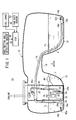
- a fuel tank 10 As shown in FIG. 1 , a fuel tank 10 according to an embodiment of the present invention is incorporated into a fuel supply system 12.
- the fuel tank 10 is constructed as a saddle-type fuel tank, and is mounted onto a non-illustrated vehicle.
- An upwardly curved saddle portion 14 is disposed in a substantially central bottom part in the vehicle widthwise direction (the direction of the arrow A) of the fuel tank 10.
- a main tank portion (first reservoir portion) 16 and a sub-tank portion (second reservoir portion) 18 are formed by the saddle portion 14.
- a fuel pump module 20 is disposed in the main tank portion 16.
- a fuel pump 22 constituting part of the fuel pump module 20 is equipped with a pumping jet pump 24, having a fuel suction inlet 24a that opens at a bottom part 16a of the main tank portion 16, whereas a pressure regulator 26 is connected on an outlet side of the fuel pump 22.
- the pressure regulator 26 supplies fuel F to a non-illustrated engine via a fuel pipeline 28 and comprises a suction branching pipe 30. On one end (lower end) of the suction branching pipe 30, a suction jet pump 32 is provided.
- a siphon tube 34 is arranged across each of bottom parts 16a, 18a of the main tank portion 16 and the sub-tank portion 18.
- a three-way joint 36 is disposed at a midway upper side portion of the siphon tube 34, and in the three-way joint 36, a suction connector 36a is arranged, in which a backflow prevention valve 38 is disposed.
- One end of a suction tube 40 is connected to the suction connector 36a, and the other end of the suction tube 40 is connected to a suction side (negative pressure side) of the suction jet pump 32.
- An open end 34a of the siphon tube 34 on the side of the main tank portion 16 is disposed more toward the outer side than the suction jet pump 32, or more specifically, is disposed on the bottom part 16a of the main tank portion 16 adjacent to an outside inner wall 16b, which is separated from the sub-tank portion 18.
- a switching valve 42a is installed in the open end 34a. The switching valve 42a closes the open end 34a upon detection of air, while on the other hand, causes the open end 34a to be opened upon detection of fluid therein.
- a switching valve 42b is installed, which is closed upon detection of air, while on the other hand, is opened upon detection of liquid therein.
- a float 44 for detecting the position of a liquid surface Fs of the fuel F stored in the main tank portion 16 is disposed in the fuel pump module 20.
- a fuel gauge 46 which detects the remaining fuel amount from the liquid surface Fs detected by the float 44, is connected to an ECU (electronic control unit) 48 that serves as a controller.
- An inclination angle detecting sensor (fuel imbalance condition detector) 50 which detects an inclination angle of the fuel tank 10
- a yaw rate sensor (fuel imbalance condition detector) 52 which detects a yaw rate of the fuel tank 10, are connected to the ECU 48.
- start-up of the engine is performed in a state where the fuel F is retained only in the main tank portion 16. Owing thereto, the fuel pump 22 that constitutes the fuel pump module 20 is driven, and the fuel F, which is stored in the main tank portion 16, is drawn in from the fuel suction inlet 24a under an action of the pumping jet pump 24.
- the fuel F is supplied to the engine from the pressure regulator 26 and via the fuel pipeline 28.
- the fuel F is supplied to the suction jet pump 32 via the suction branching pipe 30, whereby a negative pressure is generated in the suction tube 40.
- the suction tube 40 communicates with the siphon tube 34 via the three-way joint 36, and suction is generated in the interior of the siphon tube 34.
- one open end 34a thereof is disposed inside the fuel F which is retained in the main tank portion 16, whereas the other open end 34b thereof is arranged in the sub-tank portion 18, which contains no fuel F therein, while the switching valve 42b thereof is closed. Accordingly, under an action of the suction jet pump 32, the interior of the siphon tube 34 is subjected to suction, and the fuel F, which is suctioned up from the one open end 34a of the siphon tube 34 is transferred over to the other open end 34b side of the siphon tube 34.
- the switching valve 42b opens and the fuel F from the main tank portion 16 side is delivered to the sub-tank portion 18 side, whereupon a siphoning function is brought about by the siphon tube 34. Owing thereto, respective liquid surfaces Fs of the fuel F in the main tank portion 16 and the fuel F that is transferred into the sub-tank portion 18 arrive at positions having the same height.
- the inclination angle detecting sensor 50 detects the inclination angle of the fuel tank 10, and when it is judged that the detected inclination angle is equal to or greater than a preset angle (for example, 5° to 6°), detection of the remaining fuel amount by the fuel gauge 46 is regulated for a fixed time only by the ECU 48.
- a preset angle for example, 5° to 6°
- the yaw rate is detected by the yaw rate sensor 52, and when it is judged that the detected yaw rate (horizontal G) is equal to or greater than a preset value (e.g., 0.1 G), detection of the remaining fuel amount by the fuel gauge 46 is regulated for a fixed time only.
- a preset value e.g., 0.1 G
- the inclination angle detected by the inclination angle detecting sensor 50 is equal to or greater than the preset angle, or when the yaw rate detected by the yaw rate sensor 52 is equal to or greater than the preset value, detection of the remaining amount by the fuel gauge 46 is halted for a fixed time only, and when normal conditions are restored and after a predetermined time thereafter (the time required for the fuel in the main tank portion 16 and the sub-tank portion 18 to be placed in balance by the siphon tube 34), detection of the remaining amount can be carried out again.
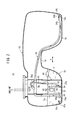
- the fuel F in the main tank portion 16 which is inclined upwardly, is transferred into the sub-tank portion 18 that is located on the downward side. Owing thereto, the liquid surfaces Fs of the main tank portion 16 and the sub-tank portion 18, respectively, can be adjusted to attain the same position.
- the siphon tube 34 can possess a desired siphoning effect, and the function whereby each of the liquid surfaces Fs of the main tank portion 16 and the sub-tank portion 18 are kept in balance can be continued and maintained.
- the open end 34a of the siphon tube 34 on the side of the main tank portion 16 is arranged more outwardly (more toward the outer side) than the suction jet pump 32. More specifically, both open ends 34a, 34b of the siphon tube 34 are disposed on respective bottom parts 16a, 18a of the main tank portion 16 and the sub-tank portion 18, and further, are disposed adjacent to the outside inner walls 16b, 18b that are separated mutually from each other. Owing thereto, when the main tank portion 16 becomes inclined with the sub-tank portion 18 being oriented downwardly therefrom, the fuel suction inlet 24a of the fuel pump 22 is positioned lower than the open end 34a of the siphon tube 34 (see FIG. 3 ).
- the switching valves 42a, 42b are installed, respectively, in both open ends 34a, 34b of the siphon tube 34, and the open ends 34a, 34b are opened only at a time when fuel F is present therein. Owing thereto, introduction of air into the interior of the siphon tube 34 is prevented, and a suitable siphoning effect can reliably be maintained.
- the siphon tube 34 can reliably and suitably maintain the desired siphoning effect, so that faults in the fuel supply to the engine can be suppressed.
Applications Claiming Priority (2)
| Application Number | Priority Date | Filing Date | Title |
|---|---|---|---|
| JP2008286410 | 2008-11-07 | ||
| PCT/JP2009/068599 WO2010053045A1 (fr) | 2008-11-07 | 2009-10-29 | Réservoir de combustible |
Publications (3)
| Publication Number | Publication Date |
|---|---|
| EP2343446A1 true EP2343446A1 (fr) | 2011-07-13 |
| EP2343446A4 EP2343446A4 (fr) | 2012-09-19 |
| EP2343446B1 EP2343446B1 (fr) | 2013-10-16 |
Family
ID=42152855
Family Applications (1)
| Application Number | Title | Priority Date | Filing Date |
|---|---|---|---|
| EP20090824745 Not-in-force EP2343446B1 (fr) | 2008-11-07 | 2009-10-29 | Reservoir de combustible |
Country Status (5)
| Country | Link |
|---|---|
| US (1) | US20110209789A1 (fr) |
| EP (1) | EP2343446B1 (fr) |
| JP (1) | JP5198578B2 (fr) |
| CN (1) | CN102197210A (fr) |
| WO (1) | WO2010053045A1 (fr) |
Cited By (3)
| Publication number | Priority date | Publication date | Assignee | Title |
|---|---|---|---|---|
| EP2554813A1 (fr) * | 2010-11-12 | 2013-02-06 | Kautex Textron GmbH & Co. KG | Réservoir de liquide, en particulier pour une solution d'urée aqueuse |
| EP2826656A1 (fr) * | 2013-07-03 | 2015-01-21 | CLAAS Tractor SAS | Véhicule agricole |
| EP3832122A1 (fr) * | 2019-12-06 | 2021-06-09 | Hamm AG | Système de réservoir |
Families Citing this family (17)
| Publication number | Priority date | Publication date | Assignee | Title |
|---|---|---|---|---|
| DE102010062075A1 (de) * | 2010-11-26 | 2012-05-31 | Robert Bosch Gmbh | Tankanordnung mit mechanischem Druckregler sowie Fahrzeug |
| JP5739208B2 (ja) * | 2011-04-01 | 2015-06-24 | 本田技研工業株式会社 | 燃料タンクシステム |
| GB2490557B (en) * | 2011-08-17 | 2013-12-25 | Land Rover Uk Ltd | Fuel tank assembly |
| CN102808710B (zh) * | 2012-08-20 | 2016-06-01 | 联合汽车电子有限公司 | 油泵支架总成的远端吸油结构 |
| JP6020814B2 (ja) * | 2012-12-14 | 2016-11-02 | 三菱自動車エンジニアリング株式会社 | 車両のタンク構造 |
| US9676605B2 (en) * | 2012-12-18 | 2017-06-13 | Fluor Technologies Corporation | Fuel and lubrication truck platform |
| KR101371761B1 (ko) * | 2012-12-26 | 2014-03-07 | 기아자동차(주) | Lpg봄베장치 |
| WO2015112576A1 (fr) | 2014-01-21 | 2015-07-30 | Joy Mm Delaware, Inc. | Système d'équilibrage de réservoirs de fluide pour machine minière |
| CN104228558A (zh) * | 2014-10-06 | 2014-12-24 | 张纪山 | 一种应用在轮式车辆上的燃油箱总成 |
| DE102015217609A1 (de) * | 2015-09-15 | 2017-03-16 | Kautex Textron Gmbh & Co. Kg | Betriebsflüssigkeitsbehälter für ein Kraftfahrzeug |
| DE102015219858A1 (de) * | 2015-10-13 | 2017-04-13 | Kautex Textron Gmbh & Co. Kg | Betriebsflüssigkeitsbehältersystem für Kraftfahrzeuge und Verfahren zum Befüllen eines Kraftstoffbehälters eines Betriebsflüssigkeitsbehältersystems |
| JP6651379B2 (ja) * | 2016-02-23 | 2020-02-19 | 本田技研工業株式会社 | 内燃機関の制御装置 |
| US9809111B1 (en) * | 2016-11-22 | 2017-11-07 | Samuel J. Dana | Anti-siphon device |
| US10520136B2 (en) | 2017-02-23 | 2019-12-31 | Blossman Services, Inc. | System and method for refueling a vehicle tank with liquified petroleum (LP) gas |
| EP3403864B1 (fr) * | 2017-05-18 | 2020-01-08 | Ningbo Geely Automobile Research & Development Co., Ltd. | Ensemble éjecteur de carburant pour un véhicule |
| EP3636551B1 (fr) * | 2018-10-09 | 2021-06-23 | Bombardier Inc. | Système de carburant d'aéronef et procédé associé |
| US11852111B1 (en) * | 2022-08-31 | 2023-12-26 | Ford Global Technologies, Llc | Apparatus preventing fuel starvation on inclined surfaces |
Citations (3)
| Publication number | Priority date | Publication date | Assignee | Title |
|---|---|---|---|---|
| EP0806318A2 (fr) * | 1996-05-09 | 1997-11-12 | Robert Bosch Gmbh | Installation d'alimentation de carburant pour un véhicule automobile |
| JPH1061515A (ja) * | 1996-07-01 | 1998-03-03 | Walbro Corp | 燃料タンクレベル均衡装置 |
| DE19900378A1 (de) * | 1999-01-08 | 2000-07-20 | Mannesmann Vdo Ag | Tanksystem |
Family Cites Families (9)
| Publication number | Priority date | Publication date | Assignee | Title |
|---|---|---|---|---|
| JPH075028B2 (ja) * | 1986-02-21 | 1995-01-25 | 日産自動車株式会社 | 燃料タンクの燃料吸込装置 |
| JPS6393626A (ja) * | 1986-10-08 | 1988-04-23 | Daihatsu Motor Co Ltd | 燃料タンク |
| JPH0237163A (ja) * | 1988-07-27 | 1990-02-07 | Mitsubishi Motors Corp | 車輌の燃料供給装置 |
| JPH075028A (ja) * | 1993-06-16 | 1995-01-10 | Sumitomo Metal Mining Co Ltd | 振動検出素子 |
| DE10005185A1 (de) * | 2000-02-05 | 2001-08-09 | Bosch Gmbh Robert | Verfahren und Vorrichtung zur Überwachung von Fahrzeug- und/oder Steuerfunktionen |
| US6505644B2 (en) * | 2000-06-09 | 2003-01-14 | Delphi Technologies, Inc. | Dual barrel jet fuel pump assembly for a fuel tank |
| JP4151424B2 (ja) * | 2003-01-29 | 2008-09-17 | いすゞ自動車株式会社 | 車速制限制御装置 |
| JP2004232547A (ja) * | 2003-01-30 | 2004-08-19 | Mazda Motor Corp | 車両のフュエルメータ制御装置 |
| US6871640B2 (en) * | 2003-03-18 | 2005-03-29 | Ti Group Automotive Systems, Inc. | Saddle tank siphon primer |
-
2009
- 2009-10-29 CN CN200980142916.8A patent/CN102197210A/zh active Pending
- 2009-10-29 JP JP2010536752A patent/JP5198578B2/ja not_active Expired - Fee Related
- 2009-10-29 EP EP20090824745 patent/EP2343446B1/fr not_active Not-in-force
- 2009-10-29 US US13/127,384 patent/US20110209789A1/en not_active Abandoned
- 2009-10-29 WO PCT/JP2009/068599 patent/WO2010053045A1/fr active Application Filing
Patent Citations (3)
| Publication number | Priority date | Publication date | Assignee | Title |
|---|---|---|---|---|
| EP0806318A2 (fr) * | 1996-05-09 | 1997-11-12 | Robert Bosch Gmbh | Installation d'alimentation de carburant pour un véhicule automobile |
| JPH1061515A (ja) * | 1996-07-01 | 1998-03-03 | Walbro Corp | 燃料タンクレベル均衡装置 |
| DE19900378A1 (de) * | 1999-01-08 | 2000-07-20 | Mannesmann Vdo Ag | Tanksystem |
Non-Patent Citations (1)
| Title |
|---|
| See also references of WO2010053045A1 * |
Cited By (4)
| Publication number | Priority date | Publication date | Assignee | Title |
|---|---|---|---|---|
| EP2554813A1 (fr) * | 2010-11-12 | 2013-02-06 | Kautex Textron GmbH & Co. KG | Réservoir de liquide, en particulier pour une solution d'urée aqueuse |
| EP2826656A1 (fr) * | 2013-07-03 | 2015-01-21 | CLAAS Tractor SAS | Véhicule agricole |
| EP3832122A1 (fr) * | 2019-12-06 | 2021-06-09 | Hamm AG | Système de réservoir |
| US11541748B2 (en) | 2019-12-06 | 2023-01-03 | Hamm Ag | Tank system |
Also Published As
| Publication number | Publication date |
|---|---|
| JPWO2010053045A1 (ja) | 2012-04-05 |
| JP5198578B2 (ja) | 2013-05-15 |
| EP2343446B1 (fr) | 2013-10-16 |
| WO2010053045A1 (fr) | 2010-05-14 |
| US20110209789A1 (en) | 2011-09-01 |
| CN102197210A (zh) | 2011-09-21 |
| EP2343446A4 (fr) | 2012-09-19 |
Similar Documents
| Publication | Publication Date | Title |
|---|---|---|
| EP2343446B1 (fr) | Reservoir de combustible | |
| EP2376303B1 (fr) | Agencement de réservoir et véhicule comprenant un agencement de réservoir | |
| US20020148510A1 (en) | Fuel tank | |
| US6792966B2 (en) | Fuel transfer pump and control | |
| US7484500B2 (en) | Fuel vapor treatment apparatus | |
| JP4996250B2 (ja) | 自動車用の燃料タンク | |
| US6871640B2 (en) | Saddle tank siphon primer | |
| KR101169487B1 (ko) | 차량용 연료 공급 장치 | |
| US20030173365A1 (en) | Fuel tank having a venting system | |
| EP2748454B1 (fr) | Dispositif de piège à carburant liquide | |
| US20100132451A1 (en) | Method and device for determining volume during transfer of a liquid | |
| US20180304743A1 (en) | Fuel tank having additional reserve volume | |
| JP5359472B2 (ja) | 燃料供給装置 | |
| SE1450562A1 (sv) | Bränslesystem för förbränningsmotor och ett förfarande för att reglera ett bränslesystem | |
| US20210114453A1 (en) | Method and apparatus for controlling vapor recirculation in a gasoline fuel tank | |
| SE534065C2 (sv) | Bränslesystem med tryckluftanslutet venturirör för överföring av bränsle mellan två tankar och ett fordon innefattande nämnda bränslesystem | |
| EP1538330A1 (fr) | System d'alimentation de carburant auto-purgant pour un moteur diesel avec pompe d'alimentation remplissée par gravitation | |
| JP2006161700A (ja) | 燃料供給装置 | |
| JPH08219852A (ja) | 液体輸送車両の液面検出装置 | |
| JP2010179756A (ja) | 燃料タンクシステム | |
| US20160121713A1 (en) | Method for operating a fuel tank system for an automobile and corresponding fuel tank system | |
| JP5006932B2 (ja) | 自動車用の燃料タンク | |
| JP2011021551A (ja) | 燃料タンク | |
| JPH11157600A (ja) | 給油装置 | |
| JP2002002899A (ja) | 給油所貯油タンクの在庫量調整装置 |
Legal Events
| Date | Code | Title | Description |
|---|---|---|---|
| PUAI | Public reference made under article 153(3) epc to a published international application that has entered the european phase |
Free format text: ORIGINAL CODE: 0009012 |
|
| 17P | Request for examination filed |
Effective date: 20110506 |
|
| AK | Designated contracting states |
Kind code of ref document: A1 Designated state(s): AT BE BG CH CY CZ DE DK EE ES FI FR GB GR HR HU IE IS IT LI LT LU LV MC MK MT NL NO PL PT RO SE SI SK SM TR |
|
| AX | Request for extension of the european patent |
Extension state: AL BA RS |
|
| DAX | Request for extension of the european patent (deleted) | ||
| A4 | Supplementary search report drawn up and despatched |
Effective date: 20120821 |
|
| RIC1 | Information provided on ipc code assigned before grant |
Ipc: F02M 37/00 20060101ALI20120814BHEP Ipc: F02M 37/02 20060101ALI20120814BHEP Ipc: B60K 15/03 20060101ALI20120814BHEP Ipc: F02M 37/10 20060101ALI20120814BHEP Ipc: F02M 37/18 20060101AFI20120814BHEP |
|
| 17Q | First examination report despatched |
Effective date: 20121005 |
|
| GRAP | Despatch of communication of intention to grant a patent |
Free format text: ORIGINAL CODE: EPIDOSNIGR1 |
|
| INTG | Intention to grant announced |
Effective date: 20130514 |
|
| GRAS | Grant fee paid |
Free format text: ORIGINAL CODE: EPIDOSNIGR3 |
|
| GRAA | (expected) grant |
Free format text: ORIGINAL CODE: 0009210 |
|
| AK | Designated contracting states |
Kind code of ref document: B1 Designated state(s): AT BE BG CH CY CZ DE DK EE ES FI FR GB GR HR HU IE IS IT LI LT LU LV MC MK MT NL NO PL PT RO SE SI SK SM TR |
|
| REG | Reference to a national code |
Ref country code: GB Ref legal event code: FG4D |
|
| REG | Reference to a national code |
Ref country code: CH Ref legal event code: EP |
|
| REG | Reference to a national code |
Ref country code: IE Ref legal event code: FG4D |
|
| REG | Reference to a national code |
Ref country code: AT Ref legal event code: REF Ref document number: 636636 Country of ref document: AT Kind code of ref document: T Effective date: 20131115 |
|
| REG | Reference to a national code |
Ref country code: DE Ref legal event code: R096 Ref document number: 602009019539 Country of ref document: DE Effective date: 20131212 |
|
| REG | Reference to a national code |
Ref country code: NL Ref legal event code: VDEP Effective date: 20131016 |
|
| REG | Reference to a national code |
Ref country code: AT Ref legal event code: MK05 Ref document number: 636636 Country of ref document: AT Kind code of ref document: T Effective date: 20131016 |
|
| REG | Reference to a national code |
Ref country code: LT Ref legal event code: MG4D |
|
| PG25 | Lapsed in a contracting state [announced via postgrant information from national office to epo] |
Ref country code: SE Free format text: LAPSE BECAUSE OF FAILURE TO SUBMIT A TRANSLATION OF THE DESCRIPTION OR TO PAY THE FEE WITHIN THE PRESCRIBED TIME-LIMIT Effective date: 20131016 Ref country code: LT Free format text: LAPSE BECAUSE OF FAILURE TO SUBMIT A TRANSLATION OF THE DESCRIPTION OR TO PAY THE FEE WITHIN THE PRESCRIBED TIME-LIMIT Effective date: 20131016 Ref country code: BE Free format text: LAPSE BECAUSE OF FAILURE TO SUBMIT A TRANSLATION OF THE DESCRIPTION OR TO PAY THE FEE WITHIN THE PRESCRIBED TIME-LIMIT Effective date: 20131016 Ref country code: HR Free format text: LAPSE BECAUSE OF FAILURE TO SUBMIT A TRANSLATION OF THE DESCRIPTION OR TO PAY THE FEE WITHIN THE PRESCRIBED TIME-LIMIT Effective date: 20131016 Ref country code: NL Free format text: LAPSE BECAUSE OF FAILURE TO SUBMIT A TRANSLATION OF THE DESCRIPTION OR TO PAY THE FEE WITHIN THE PRESCRIBED TIME-LIMIT Effective date: 20131016 Ref country code: IS Free format text: LAPSE BECAUSE OF FAILURE TO SUBMIT A TRANSLATION OF THE DESCRIPTION OR TO PAY THE FEE WITHIN THE PRESCRIBED TIME-LIMIT Effective date: 20140216 Ref country code: FI Free format text: LAPSE BECAUSE OF FAILURE TO SUBMIT A TRANSLATION OF THE DESCRIPTION OR TO PAY THE FEE WITHIN THE PRESCRIBED TIME-LIMIT Effective date: 20131016 Ref country code: NO Free format text: LAPSE BECAUSE OF FAILURE TO SUBMIT A TRANSLATION OF THE DESCRIPTION OR TO PAY THE FEE WITHIN THE PRESCRIBED TIME-LIMIT Effective date: 20140116 |
|
| PG25 | Lapsed in a contracting state [announced via postgrant information from national office to epo] |
Ref country code: LV Free format text: LAPSE BECAUSE OF FAILURE TO SUBMIT A TRANSLATION OF THE DESCRIPTION OR TO PAY THE FEE WITHIN THE PRESCRIBED TIME-LIMIT Effective date: 20131016 Ref country code: ES Free format text: LAPSE BECAUSE OF FAILURE TO SUBMIT A TRANSLATION OF THE DESCRIPTION OR TO PAY THE FEE WITHIN THE PRESCRIBED TIME-LIMIT Effective date: 20131016 Ref country code: CY Free format text: LAPSE BECAUSE OF FAILURE TO SUBMIT A TRANSLATION OF THE DESCRIPTION OR TO PAY THE FEE WITHIN THE PRESCRIBED TIME-LIMIT Effective date: 20131016 Ref country code: AT Free format text: LAPSE BECAUSE OF FAILURE TO SUBMIT A TRANSLATION OF THE DESCRIPTION OR TO PAY THE FEE WITHIN THE PRESCRIBED TIME-LIMIT Effective date: 20131016 |
|
| REG | Reference to a national code |
Ref country code: CH Ref legal event code: PL |
|
| PG25 | Lapsed in a contracting state [announced via postgrant information from national office to epo] |
Ref country code: PT Free format text: LAPSE BECAUSE OF FAILURE TO SUBMIT A TRANSLATION OF THE DESCRIPTION OR TO PAY THE FEE WITHIN THE PRESCRIBED TIME-LIMIT Effective date: 20140217 |
|
| REG | Reference to a national code |
Ref country code: DE Ref legal event code: R097 Ref document number: 602009019539 Country of ref document: DE |
|
| REG | Reference to a national code |
Ref country code: IE Ref legal event code: MM4A |
|
| PG25 | Lapsed in a contracting state [announced via postgrant information from national office to epo] |
Ref country code: CH Free format text: LAPSE BECAUSE OF NON-PAYMENT OF DUE FEES Effective date: 20131031 Ref country code: LI Free format text: LAPSE BECAUSE OF NON-PAYMENT OF DUE FEES Effective date: 20131031 Ref country code: MC Free format text: LAPSE BECAUSE OF FAILURE TO SUBMIT A TRANSLATION OF THE DESCRIPTION OR TO PAY THE FEE WITHIN THE PRESCRIBED TIME-LIMIT Effective date: 20131016 Ref country code: EE Free format text: LAPSE BECAUSE OF FAILURE TO SUBMIT A TRANSLATION OF THE DESCRIPTION OR TO PAY THE FEE WITHIN THE PRESCRIBED TIME-LIMIT Effective date: 20131016 |
|
| REG | Reference to a national code |
Ref country code: DE Ref legal event code: R084 Ref document number: 602009019539 Country of ref document: DE |
|
| PLBE | No opposition filed within time limit |
Free format text: ORIGINAL CODE: 0009261 |
|
| STAA | Information on the status of an ep patent application or granted ep patent |
Free format text: STATUS: NO OPPOSITION FILED WITHIN TIME LIMIT |
|
| PG25 | Lapsed in a contracting state [announced via postgrant information from national office to epo] |
Ref country code: CZ Free format text: LAPSE BECAUSE OF FAILURE TO SUBMIT A TRANSLATION OF THE DESCRIPTION OR TO PAY THE FEE WITHIN THE PRESCRIBED TIME-LIMIT Effective date: 20131016 Ref country code: RO Free format text: LAPSE BECAUSE OF FAILURE TO SUBMIT A TRANSLATION OF THE DESCRIPTION OR TO PAY THE FEE WITHIN THE PRESCRIBED TIME-LIMIT Effective date: 20131016 Ref country code: SK Free format text: LAPSE BECAUSE OF FAILURE TO SUBMIT A TRANSLATION OF THE DESCRIPTION OR TO PAY THE FEE WITHIN THE PRESCRIBED TIME-LIMIT Effective date: 20131016 Ref country code: PL Free format text: LAPSE BECAUSE OF FAILURE TO SUBMIT A TRANSLATION OF THE DESCRIPTION OR TO PAY THE FEE WITHIN THE PRESCRIBED TIME-LIMIT Effective date: 20131016 Ref country code: IT Free format text: LAPSE BECAUSE OF FAILURE TO SUBMIT A TRANSLATION OF THE DESCRIPTION OR TO PAY THE FEE WITHIN THE PRESCRIBED TIME-LIMIT Effective date: 20131016 |
|
| 26N | No opposition filed |
Effective date: 20140717 |
|
| GBPC | Gb: european patent ceased through non-payment of renewal fee |
Effective date: 20140116 |
|
| PG25 | Lapsed in a contracting state [announced via postgrant information from national office to epo] |
Ref country code: DK Free format text: LAPSE BECAUSE OF FAILURE TO SUBMIT A TRANSLATION OF THE DESCRIPTION OR TO PAY THE FEE WITHIN THE PRESCRIBED TIME-LIMIT Effective date: 20131016 |
|
| REG | Reference to a national code |
Ref country code: DE Ref legal event code: R084 Ref document number: 602009019539 Country of ref document: DE Effective date: 20140821 |
|
| REG | Reference to a national code |
Ref country code: DE Ref legal event code: R097 Ref document number: 602009019539 Country of ref document: DE Effective date: 20140717 |
|
| PG25 | Lapsed in a contracting state [announced via postgrant information from national office to epo] |
Ref country code: IE Free format text: LAPSE BECAUSE OF NON-PAYMENT OF DUE FEES Effective date: 20131029 |
|
| PG25 | Lapsed in a contracting state [announced via postgrant information from national office to epo] |
Ref country code: GB Free format text: LAPSE BECAUSE OF NON-PAYMENT OF DUE FEES Effective date: 20140116 |
|
| PG25 | Lapsed in a contracting state [announced via postgrant information from national office to epo] |
Ref country code: SI Free format text: LAPSE BECAUSE OF FAILURE TO SUBMIT A TRANSLATION OF THE DESCRIPTION OR TO PAY THE FEE WITHIN THE PRESCRIBED TIME-LIMIT Effective date: 20131016 |
|
| PG25 | Lapsed in a contracting state [announced via postgrant information from national office to epo] |
Ref country code: SM Free format text: LAPSE BECAUSE OF FAILURE TO SUBMIT A TRANSLATION OF THE DESCRIPTION OR TO PAY THE FEE WITHIN THE PRESCRIBED TIME-LIMIT Effective date: 20131016 |
|
| PG25 | Lapsed in a contracting state [announced via postgrant information from national office to epo] |
Ref country code: TR Free format text: LAPSE BECAUSE OF FAILURE TO SUBMIT A TRANSLATION OF THE DESCRIPTION OR TO PAY THE FEE WITHIN THE PRESCRIBED TIME-LIMIT Effective date: 20131016 |
|
| PG25 | Lapsed in a contracting state [announced via postgrant information from national office to epo] |
Ref country code: HU Free format text: LAPSE BECAUSE OF FAILURE TO SUBMIT A TRANSLATION OF THE DESCRIPTION OR TO PAY THE FEE WITHIN THE PRESCRIBED TIME-LIMIT; INVALID AB INITIO Effective date: 20091029 Ref country code: MK Free format text: LAPSE BECAUSE OF FAILURE TO SUBMIT A TRANSLATION OF THE DESCRIPTION OR TO PAY THE FEE WITHIN THE PRESCRIBED TIME-LIMIT Effective date: 20131016 Ref country code: LU Free format text: LAPSE BECAUSE OF NON-PAYMENT OF DUE FEES Effective date: 20131029 Ref country code: BG Free format text: LAPSE BECAUSE OF FAILURE TO SUBMIT A TRANSLATION OF THE DESCRIPTION OR TO PAY THE FEE WITHIN THE PRESCRIBED TIME-LIMIT Effective date: 20131016 |
|
| PG25 | Lapsed in a contracting state [announced via postgrant information from national office to epo] |
Ref country code: MT Free format text: LAPSE BECAUSE OF FAILURE TO SUBMIT A TRANSLATION OF THE DESCRIPTION OR TO PAY THE FEE WITHIN THE PRESCRIBED TIME-LIMIT Effective date: 20131016 Ref country code: GR Free format text: LAPSE BECAUSE OF NON-PAYMENT OF DUE FEES Effective date: 20131016 |
|
| REG | Reference to a national code |
Ref country code: FR Ref legal event code: PLFP Year of fee payment: 7 |
|
| PGFP | Annual fee paid to national office [announced via postgrant information from national office to epo] |
Ref country code: FR Payment date: 20150908 Year of fee payment: 7 |
|
| PG25 | Lapsed in a contracting state [announced via postgrant information from national office to epo] |
Ref country code: GR Free format text: LAPSE BECAUSE OF FAILURE TO SUBMIT A TRANSLATION OF THE DESCRIPTION OR TO PAY THE FEE WITHIN THE PRESCRIBED TIME-LIMIT Effective date: 20140117 |
|
| REG | Reference to a national code |
Ref country code: FR Ref legal event code: ST Effective date: 20170630 |
|
| PG25 | Lapsed in a contracting state [announced via postgrant information from national office to epo] |
Ref country code: FR Free format text: LAPSE BECAUSE OF NON-PAYMENT OF DUE FEES Effective date: 20161102 |
|
| PGFP | Annual fee paid to national office [announced via postgrant information from national office to epo] |
Ref country code: DE Payment date: 20171025 Year of fee payment: 9 |
|
| REG | Reference to a national code |
Ref country code: DE Ref legal event code: R119 Ref document number: 602009019539 Country of ref document: DE |
|
| PG25 | Lapsed in a contracting state [announced via postgrant information from national office to epo] |
Ref country code: DE Free format text: LAPSE BECAUSE OF NON-PAYMENT OF DUE FEES Effective date: 20190501 |