EP2343446A1 - Fuel tank - Google Patents
Fuel tank Download PDFInfo
- Publication number
- EP2343446A1 EP2343446A1 EP09824745A EP09824745A EP2343446A1 EP 2343446 A1 EP2343446 A1 EP 2343446A1 EP 09824745 A EP09824745 A EP 09824745A EP 09824745 A EP09824745 A EP 09824745A EP 2343446 A1 EP2343446 A1 EP 2343446A1
- Authority
- EP
- European Patent Office
- Prior art keywords
- fuel
- reservoir portion
- disposed
- siphon tube
- fuel tank
- Prior art date
- Legal status (The legal status is an assumption and is not a legal conclusion. Google has not performed a legal analysis and makes no representation as to the accuracy of the status listed.)
- Granted
Links
Images


Classifications
-
- F—MECHANICAL ENGINEERING; LIGHTING; HEATING; WEAPONS; BLASTING
- F02—COMBUSTION ENGINES; HOT-GAS OR COMBUSTION-PRODUCT ENGINE PLANTS
- F02M—SUPPLYING COMBUSTION ENGINES IN GENERAL WITH COMBUSTIBLE MIXTURES OR CONSTITUENTS THEREOF
- F02M37/00—Apparatus or systems for feeding liquid fuel from storage containers to carburettors or fuel-injection apparatus; Arrangements for purifying liquid fuel specially adapted for, or arranged on, internal-combustion engines
- F02M37/04—Feeding by means of driven pumps
- F02M37/08—Feeding by means of driven pumps electrically driven
- F02M37/10—Feeding by means of driven pumps electrically driven submerged in fuel, e.g. in reservoir
- F02M37/106—Feeding by means of driven pumps electrically driven submerged in fuel, e.g. in reservoir the pump being installed in a sub-tank
-
- B—PERFORMING OPERATIONS; TRANSPORTING
- B60—VEHICLES IN GENERAL
- B60K—ARRANGEMENT OR MOUNTING OF PROPULSION UNITS OR OF TRANSMISSIONS IN VEHICLES; ARRANGEMENT OR MOUNTING OF PLURAL DIVERSE PRIME-MOVERS IN VEHICLES; AUXILIARY DRIVES FOR VEHICLES; INSTRUMENTATION OR DASHBOARDS FOR VEHICLES; ARRANGEMENTS IN CONNECTION WITH COOLING, AIR INTAKE, GAS EXHAUST OR FUEL SUPPLY OF PROPULSION UNITS IN VEHICLES
- B60K15/00—Arrangement in connection with fuel supply of combustion engines or other fuel consuming energy converters, e.g. fuel cells; Mounting or construction of fuel tanks
- B60K15/03—Fuel tanks
-
- F—MECHANICAL ENGINEERING; LIGHTING; HEATING; WEAPONS; BLASTING
- F02—COMBUSTION ENGINES; HOT-GAS OR COMBUSTION-PRODUCT ENGINE PLANTS
- F02M—SUPPLYING COMBUSTION ENGINES IN GENERAL WITH COMBUSTIBLE MIXTURES OR CONSTITUENTS THEREOF
- F02M37/00—Apparatus or systems for feeding liquid fuel from storage containers to carburettors or fuel-injection apparatus; Arrangements for purifying liquid fuel specially adapted for, or arranged on, internal-combustion engines
- F02M37/0076—Details of the fuel feeding system related to the fuel tank
- F02M37/0088—Multiple separate fuel tanks or tanks being at least partially partitioned
- F02M37/0094—Saddle tanks; Tanks having partition walls
-
- F—MECHANICAL ENGINEERING; LIGHTING; HEATING; WEAPONS; BLASTING
- F02—COMBUSTION ENGINES; HOT-GAS OR COMBUSTION-PRODUCT ENGINE PLANTS
- F02M—SUPPLYING COMBUSTION ENGINES IN GENERAL WITH COMBUSTIBLE MIXTURES OR CONSTITUENTS THEREOF
- F02M37/00—Apparatus or systems for feeding liquid fuel from storage containers to carburettors or fuel-injection apparatus; Arrangements for purifying liquid fuel specially adapted for, or arranged on, internal-combustion engines
- F02M37/02—Feeding by means of suction apparatus, e.g. by air flow through carburettors
- F02M37/025—Feeding by means of a liquid fuel-driven jet pump
-
- B—PERFORMING OPERATIONS; TRANSPORTING
- B60—VEHICLES IN GENERAL
- B60K—ARRANGEMENT OR MOUNTING OF PROPULSION UNITS OR OF TRANSMISSIONS IN VEHICLES; ARRANGEMENT OR MOUNTING OF PLURAL DIVERSE PRIME-MOVERS IN VEHICLES; AUXILIARY DRIVES FOR VEHICLES; INSTRUMENTATION OR DASHBOARDS FOR VEHICLES; ARRANGEMENTS IN CONNECTION WITH COOLING, AIR INTAKE, GAS EXHAUST OR FUEL SUPPLY OF PROPULSION UNITS IN VEHICLES
- B60K15/00—Arrangement in connection with fuel supply of combustion engines or other fuel consuming energy converters, e.g. fuel cells; Mounting or construction of fuel tanks
- B60K15/03—Fuel tanks
- B60K2015/03118—Multiple tanks, i.e. two or more separate tanks
- B60K2015/03138—Pumping means between the compartments
-
- Y—GENERAL TAGGING OF NEW TECHNOLOGICAL DEVELOPMENTS; GENERAL TAGGING OF CROSS-SECTIONAL TECHNOLOGIES SPANNING OVER SEVERAL SECTIONS OF THE IPC; TECHNICAL SUBJECTS COVERED BY FORMER USPC CROSS-REFERENCE ART COLLECTIONS [XRACs] AND DIGESTS
- Y10—TECHNICAL SUBJECTS COVERED BY FORMER USPC
- Y10T—TECHNICAL SUBJECTS COVERED BY FORMER US CLASSIFICATION
- Y10T137/00—Fluid handling
- Y10T137/6851—With casing, support, protector or static constructional installations
- Y10T137/6855—Vehicle
Landscapes
- Engineering & Computer Science (AREA)
- Chemical & Material Sciences (AREA)
- Combustion & Propulsion (AREA)
- Mechanical Engineering (AREA)
- General Engineering & Computer Science (AREA)
- Life Sciences & Earth Sciences (AREA)
- Sustainable Development (AREA)
- Sustainable Energy (AREA)
- Transportation (AREA)
- Cooling, Air Intake And Gas Exhaust, And Fuel Tank Arrangements In Propulsion Units (AREA)
Abstract
Description
- The present invention relates to a fuel tank equipped with a fuel pump, a first reservoir portion in which the fuel pump is arranged and in which a fuel is retained, a second reservoir portion in which the fuel is retained, and a siphon tube disposed across the first reservoir portion and the second reservoir portion, suction being carried out in the siphon tube via the fuel pump.
- A fuel tank is used for supplying fuel to an internal combustion engine. For example, in a 4WD (four wheel drive) vehicle or a FR (front engine, rear drive) vehicle, in order to avoid the propeller shaft that passes through the center of the vehicle, a so-called saddle type fuel tank, in which the center of a bottom part of the fuel tank in the widthwise direction of the vehicle is recessed upwardly, has been adopted.
- Generally, a saddle type fuel tank is divided into a first reservoir portion that retains fuel, and a second reservoir portion that also retains fuel therein. In the first reservoir portion and the second reservoir portion, systems are installed respectively for transporting (i.e., pumping) the fuel. For this reason, compared to a 2WD (two wheel drive) vehicle, two respective fuel pumping systems are required, which leads to a rise in cost and increases the scale of the fuel tank.
- Thus, a fuel tank level balancing device is known, as disclosed in Japanese Laid-Open Patent Publication No.
10-061515 FIG. 5 , includes a fuel tank 1 having two dividedcompartments compartments siphon 2. - A
fuel pump module 3 is disposed in the dividedcompartment 1b, and in an outlet of thefuel pump module 3, a bypass pressure regulator 4 is disposed. A conduit pipe 5 is connected to an outlet of the regulator 4, whereby a liquid fuel is supplied through the conduit pipe 5 to anozzle 6a of aninjection pump 6. Theinjection pump 6 is operated by the liquid fuel, which is supplied to thenozzle 6a, such that fuel is suctioned through the interior of thesiphon 2 from each of tworespective fuel pickups - As a result thereof, the fuel levels in the divided
compartments siphon 2, and the overall fuel level of the vehicle can be monitored with a singlefuel level sensor 7. - In the aforementioned Japanese Laid-Open Patent Publication No.
10-061515 fuel pickups siphon 2, are arranged on the inside interior walls (inner walls that are mutually adjacent to each other) of the dividedcompartments - In particular, in the case that the fuel tank 1 is inclined in the direction of the arrow A1, the
fuel pickup 2b is disposed downwardly from (i.e., at a lower position than) asuction inlet 3a of thefuel pump module 3. Accordingly, almost all of the fuel in the dividedcompartment 1b becomes transferred, via thefuel pickup 2b, to the side of the dividedcompartment 1a. As a result, fuel cannot be supplied through thepump module 3, and the start-up performance of the engine is deteriorated. - The present invention is made to resolve this type of problem. An object of the invention is to provide a fuel tank which suppresses excess transfer of fuel in an amount more than needed between a first reservoir portion and a second reservoir portion, at times when the vehicle is being driven around a curve, or when the vehicle is parked on an incline, and which enables the engine to reliably be started by means of a simple structure.
- The present invention concerns a fuel tank comprising a fuel pump, a first reservoir portion in which the fuel pump is arranged and in which a fuel is retained, a second reservoir portion in which the fuel is retained, and a siphon tube disposed across the first reservoir portion and the second reservoir portion, suction being carried out in the siphon tube via the fuel pump.
- In the fuel tank, an open end of the siphon tube, which opens into the first reservoir portion, is disposed more toward an outer side of the fuel tank than the fuel pump.
- With the present invention, the open end of the siphon tube that opens into the first reservoir portion is disposed more outwardly, i.e., closer to the outer side, than the fuel pump. Owing thereto, when the vehicle is driven around a curve or is parked on an incline, excessive transfer of fuel in an amount more than needed, in particular, from the first reservoir portion in which the fuel pump is disposed to the second reservoir portion, can be prevented from occurring. Accordingly, by means of a simple structure, fuel can reliably be supplied to the engine via the fuel pump, and the start-up performance of the engine can suitably be improved.
- The above objects, features and advantages shall be made clearer from the following explanation of a preferred embodiment of the invention, presented in conjunction with the appended drawings.
-
-
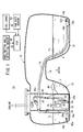
FIG. 1 is a schematic structural view of a fuel supply system, in which a fuel tank according to an embodiment of the invention is incorporated; -
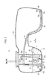
FIG. 2 is a view describing the fuel tank in a condition when it is shipped from the factory; -
FIG. 3 is a view describing the fuel tank in a condition when the vehicle is parked on an incline, or when the vehicle is being driven around a curve; -
FIG. 4 is a view describing the fuel tank in a condition when the vehicle is being driven in a continuously revolving manner; and -
FIG. 5 is a view describing a fuel tank level balancing device as disclosed in Japanese Laid-Open Patent Publication No.10-061515 - As shown in
FIG. 1 , afuel tank 10 according to an embodiment of the present invention is incorporated into afuel supply system 12. Thefuel tank 10 is constructed as a saddle-type fuel tank, and is mounted onto a non-illustrated vehicle. An upwardlycurved saddle portion 14 is disposed in a substantially central bottom part in the vehicle widthwise direction (the direction of the arrow A) of thefuel tank 10. A main tank portion (first reservoir portion) 16 and a sub-tank portion (second reservoir portion) 18 are formed by thesaddle portion 14. - A
fuel pump module 20 is disposed in themain tank portion 16. Afuel pump 22 constituting part of thefuel pump module 20 is equipped with apumping jet pump 24, having afuel suction inlet 24a that opens at abottom part 16a of themain tank portion 16, whereas apressure regulator 26 is connected on an outlet side of thefuel pump 22. - The
pressure regulator 26 supplies fuel F to a non-illustrated engine via afuel pipeline 28 and comprises asuction branching pipe 30. On one end (lower end) of thesuction branching pipe 30, asuction jet pump 32 is provided. - Inside the
fuel tank 10, asiphon tube 34 is arranged across each ofbottom parts main tank portion 16 and thesub-tank portion 18. A three-way joint 36 is disposed at a midway upper side portion of thesiphon tube 34, and in the three-way joint 36, asuction connector 36a is arranged, in which abackflow prevention valve 38 is disposed. One end of asuction tube 40 is connected to thesuction connector 36a, and the other end of thesuction tube 40 is connected to a suction side (negative pressure side) of thesuction jet pump 32. - An
open end 34a of thesiphon tube 34 on the side of themain tank portion 16 is disposed more toward the outer side than thesuction jet pump 32, or more specifically, is disposed on thebottom part 16a of themain tank portion 16 adjacent to an outsideinner wall 16b, which is separated from thesub-tank portion 18. Aswitching valve 42a is installed in theopen end 34a. Theswitching valve 42a closes theopen end 34a upon detection of air, while on the other hand, causes theopen end 34a to be opened upon detection of fluid therein. - An
open end 34b of thesiphon tube 34 on the side of thesub-tank portion 18, in a similar manner, is disposed on thebottom part 18a of thesub-tank portion 18 adjacent to an outsideinner wall 18b, which is separated from themain tank portion 16. In theopen end 34b, aswitching valve 42b is installed, which is closed upon detection of air, while on the other hand, is opened upon detection of liquid therein. - A
float 44 for detecting the position of a liquid surface Fs of the fuel F stored in themain tank portion 16 is disposed in thefuel pump module 20. Afuel gauge 46, which detects the remaining fuel amount from the liquid surface Fs detected by thefloat 44, is connected to an ECU (electronic control unit) 48 that serves as a controller. An inclination angle detecting sensor (fuel imbalance condition detector) 50, which detects an inclination angle of thefuel tank 10, and a yaw rate sensor (fuel imbalance condition detector) 52, which detects a yaw rate of thefuel tank 10, are connected to theECU 48. - Operations of the
fuel tank 10 shall be described below in relation to thefuel supply system 12 in which thefuel tank 10 is incorporated. - At first, as shown in
FIG. 2 , for example, when shipped from the factory, start-up of the engine is performed in a state where the fuel F is retained only in themain tank portion 16. Owing thereto, thefuel pump 22 that constitutes thefuel pump module 20 is driven, and the fuel F, which is stored in themain tank portion 16, is drawn in from thefuel suction inlet 24a under an action of thepumping jet pump 24. - The fuel F is supplied to the engine from the
pressure regulator 26 and via thefuel pipeline 28. On the other hand, the fuel F is supplied to thesuction jet pump 32 via thesuction branching pipe 30, whereby a negative pressure is generated in thesuction tube 40. Thesuction tube 40 communicates with thesiphon tube 34 via the three-way joint 36, and suction is generated in the interior of thesiphon tube 34. - Concerning the
siphon tube 34, oneopen end 34a thereof is disposed inside the fuel F which is retained in themain tank portion 16, whereas the otheropen end 34b thereof is arranged in thesub-tank portion 18, which contains no fuel F therein, while theswitching valve 42b thereof is closed. Accordingly, under an action of thesuction jet pump 32, the interior of thesiphon tube 34 is subjected to suction, and the fuel F, which is suctioned up from the oneopen end 34a of thesiphon tube 34 is transferred over to the otheropen end 34b side of thesiphon tube 34. - At the
open end 34b, as a result of the fuel F being supplied thereto, theswitching valve 42b opens and the fuel F from themain tank portion 16 side is delivered to thesub-tank portion 18 side, whereupon a siphoning function is brought about by thesiphon tube 34. Owing thereto, respective liquid surfaces Fs of the fuel F in themain tank portion 16 and the fuel F that is transferred into thesub-tank portion 18 arrive at positions having the same height. - Further, as shown in
FIG. 3 , when the vehicle is parked on an incline, or when the vehicle is driven around a curve, a condition occurs in which thefuel tank 10 becomes inclined with respect to the vehicle widthwise direction (the direction of arrow A). Accordingly, it is easy for the fuel F retained in themain tank portion 16 and the fuel F maintained in thesub-tank portion 18 to become unbalanced. - Consequently, in a condition where the vehicle is parked on an incline, the inclination
angle detecting sensor 50 detects the inclination angle of thefuel tank 10, and when it is judged that the detected inclination angle is equal to or greater than a preset angle (for example, 5° to 6°), detection of the remaining fuel amount by thefuel gauge 46 is regulated for a fixed time only by theECU 48. - Further, when the vehicle is being driven around a curve, the yaw rate is detected by the
yaw rate sensor 52, and when it is judged that the detected yaw rate (horizontal G) is equal to or greater than a preset value (e.g., 0.1 G), detection of the remaining fuel amount by thefuel gauge 46 is regulated for a fixed time only. - Still further, when the inclination angle detected by the inclination
angle detecting sensor 50 is equal to or greater than the preset angle, or when the yaw rate detected by theyaw rate sensor 52 is equal to or greater than the preset value, detection of the remaining amount by thefuel gauge 46 is halted for a fixed time only, and when normal conditions are restored and after a predetermined time thereafter (the time required for the fuel in themain tank portion 16 and thesub-tank portion 18 to be placed in balance by the siphon tube 34), detection of the remaining amount can be carried out again. - As a result thereof, by regulating the detection of the remaining fuel amount in cases where a liquid surface difference at or above a prescribed value is generated between the
main tank portion 16 and thesub-tank portion 18, errors in detection of the remaining fuel amount can be prevented. - At the inclined condition of the
fuel tank 10 shown inFIG. 3 , by means of the siphoning effect of the siphontube 34, the fuel F in themain tank portion 16, which is inclined upwardly, is transferred into thesub-tank portion 18 that is located on the downward side. Owing thereto, the liquid surfaces Fs of themain tank portion 16 and thesub-tank portion 18, respectively, can be adjusted to attain the same position. - Further, when the engine is stopped, under operation of the
backflow prevention valve 38, which is arranged in thesuction connector 36a of the three-way joint 36, backflow from thesuction tube 40 to the side of the siphontube 34 does not occur. Accordingly, the siphontube 34 can possess a desired siphoning effect, and the function whereby each of the liquid surfaces Fs of themain tank portion 16 and thesub-tank portion 18 are kept in balance can be continued and maintained. - In this case, according to the present embodiment, the
open end 34a of the siphontube 34 on the side of themain tank portion 16 is arranged more outwardly (more toward the outer side) than thesuction jet pump 32. More specifically, bothopen ends tube 34 are disposed on respectivebottom parts main tank portion 16 and thesub-tank portion 18, and further, are disposed adjacent to the outsideinner walls main tank portion 16 becomes inclined with thesub-tank portion 18 being oriented downwardly therefrom, thefuel suction inlet 24a of thefuel pump 22 is positioned lower than theopen end 34a of the siphon tube 34 (seeFIG. 3 ). - As a result thereof, when the vehicle is being driven around a curve or is parked on an incline, in particular, excessive transfer of the fuel F from the
main tank portion 16 in which thefuel pump 22 is disposed into thesub-tank portion 18 can be prevented from occurring. Accordingly, with a simple structure, the fuel F can reliably be supplied to the engine through thefuel pump 22, and the start-up performance of the engine can suitably be improved. - Still further, as shown in
FIG. 4 , by the vehicle being driven in a continuously revolving manner or the like, a case may occur in which the liquid surfaces Fs inside thefuel tank 10 experience vertical variations. At this time, the switchingvalves open ends tube 34, and the open ends 34a, 34b are opened only at a time when fuel F is present therein. Owing thereto, introduction of air into the interior of the siphontube 34 is prevented, and a suitable siphoning effect can reliably be maintained. - In addition, by continuously operating the
suction jet pump 32 via thefuel pump 22, suction is normally created in the siphontube 34 via the three-way joint 36. As a result thereof, the siphontube 34 can reliably and suitably maintain the desired siphoning effect, so that faults in the fuel supply to the engine can be suppressed.
Claims (7)
- A fuel tank (10) comprising:a fuel pump (22);a first reservoir portion (16) in which the fuel pump (22) is arranged and in which a fuel is retained;a second reservoir portion (18) in which the fuel is retained; anda siphon tube (34) disposed across the first reservoir portion (16) and the second reservoir portion (18), suction being carried out in the siphon tube (34) via the fuel pump (22),wherein an open end (34a) of the siphon tube (34), which opens into the first reservoir portion (16), is disposed more toward an outer side than the fuel pump (22).
- A fuel tank according to claim 1, wherein opposite open ends (34a, 34b) of the siphon tube (34) are disposed respectively on bottom parts (16a, 18a) of the first reservoir portion (16) and the second reservoir portion (18) and adjacent to outside inner walls (16b, 18b), which are separated mutually from each other.
- A fuel tank according to claim 1, wherein a fuel suction inlet (24a) of the fuel pump (22) is disposed lower than the open end (34a) of the siphon tube (34) when the first reservoir portion (16) is inclined with the second reservoir portion (18) being oriented downwardly therefrom.
- A fuel tank according to claim 1, wherein a three-way joint (36) is disposed in the siphon tube (34), and in the three-way joint (36), a backflow prevention valve (38) is disposed within a suction connector (36a) in which suction is carried out by the fuel pump (22).
- A fuel tank according to claim 1, further comprising:a fuel imbalance condition detector for detecting a state of imbalance between the fuel of the first reservoir portion (16) and the fuel of the second reservoir portion (18); anda controller (48) for regulating, for a fixed time only, detection of a remaining fuel amount by a fuel gauge, which is disposed in the first reservoir portion (16) or the second reservoir portion (18), when the state of imbalance in the fuel is detected by the fuel imbalance condition detector.
- A fuel tank according to claim 5, wherein the fuel imbalance condition detector comprises an inclination angle detecting sensor (50), which detects an angle of inclination of the fuel tank (10), and wherein the state of imbalance in the fuel is determined by the detected angle of inclination being equal to or greater than a preset angle.
- A fuel tank according to claim 5, wherein the fuel imbalance condition detector comprises a yaw rate sensor (52), which detects a yaw rate of the fuel tank (10), and wherein the state of imbalance in the fuel is determined by the detected yaw rate being equal to or greater than a preset value.
Applications Claiming Priority (2)
| Application Number | Priority Date | Filing Date | Title |
|---|---|---|---|
| JP2008286410 | 2008-11-07 | ||
| PCT/JP2009/068599 WO2010053045A1 (en) | 2008-11-07 | 2009-10-29 | Fuel tank |
Publications (3)
| Publication Number | Publication Date |
|---|---|
| EP2343446A1 true EP2343446A1 (en) | 2011-07-13 |
| EP2343446A4 EP2343446A4 (en) | 2012-09-19 |
| EP2343446B1 EP2343446B1 (en) | 2013-10-16 |
Family
ID=42152855
Family Applications (1)
| Application Number | Title | Priority Date | Filing Date |
|---|---|---|---|
| EP20090824745 Not-in-force EP2343446B1 (en) | 2008-11-07 | 2009-10-29 | Fuel tank |
Country Status (5)
| Country | Link |
|---|---|
| US (1) | US20110209789A1 (en) |
| EP (1) | EP2343446B1 (en) |
| JP (1) | JP5198578B2 (en) |
| CN (1) | CN102197210A (en) |
| WO (1) | WO2010053045A1 (en) |
Cited By (3)
| Publication number | Priority date | Publication date | Assignee | Title |
|---|---|---|---|---|
| EP2554813A1 (en) * | 2010-11-12 | 2013-02-06 | Kautex Textron GmbH & Co. KG | Liquid reservoir, in particular for an aqueous urea solution |
| EP2826656A1 (en) * | 2013-07-03 | 2015-01-21 | CLAAS Tractor SAS | Agricultural vehicle |
| EP3832122A1 (en) * | 2019-12-06 | 2021-06-09 | Hamm AG | Tank system |
Families Citing this family (17)
| Publication number | Priority date | Publication date | Assignee | Title |
|---|---|---|---|---|
| DE102010062075A1 (en) | 2010-11-26 | 2012-05-31 | Robert Bosch Gmbh | Tank arrangement with mechanical pressure regulator and vehicle |
| JP5739208B2 (en) * | 2011-04-01 | 2015-06-24 | 本田技研工業株式会社 | Fuel tank system |
| GB2490557B (en) * | 2011-08-17 | 2013-12-25 | Land Rover Uk Ltd | Fuel tank assembly |
| CN102808710B (en) * | 2012-08-20 | 2016-06-01 | 联合汽车电子有限公司 | The far-end oil suction structure that oil pump support always becomes |
| JP6020814B2 (en) * | 2012-12-14 | 2016-11-02 | 三菱自動車エンジニアリング株式会社 | Vehicle tank structure |
| AU2013361429B2 (en) * | 2012-12-18 | 2017-02-09 | Fluor Technologies Corporation | Fuel and lubrication truck platform |
| KR101371761B1 (en) * | 2012-12-26 | 2014-03-07 | 기아자동차(주) | Lpg bombe apparatus |
| CN105917075B (en) | 2014-01-21 | 2018-05-11 | 乔伊·姆·特拉华公司 | The equal balance system of fluid cylinder for mining device |
| CN104228558A (en) * | 2014-10-06 | 2014-12-24 | 张纪山 | Fuel tank assembly applied to wheeled vehicle |
| DE102015217609A1 (en) * | 2015-09-15 | 2017-03-16 | Kautex Textron Gmbh & Co. Kg | Operating fluid container for a motor vehicle |
| DE102015219858A1 (en) * | 2015-10-13 | 2017-04-13 | Kautex Textron Gmbh & Co. Kg | Operating fluid tank system for motor vehicles and method for filling a fuel tank of a working fluid tank system |
| JP6651379B2 (en) * | 2016-02-23 | 2020-02-19 | 本田技研工業株式会社 | Control device for internal combustion engine |
| US9809111B1 (en) * | 2016-11-22 | 2017-11-07 | Samuel J. Dana | Anti-siphon device |
| US10520136B2 (en) * | 2017-02-23 | 2019-12-31 | Blossman Services, Inc. | System and method for refueling a vehicle tank with liquified petroleum (LP) gas |
| EP3403864B1 (en) | 2017-05-18 | 2020-01-08 | Ningbo Geely Automobile Research & Development Co., Ltd. | A fuel ejector assembly for a vehicle |
| EP3636551B1 (en) * | 2018-10-09 | 2021-06-23 | Bombardier Inc. | Aircraft fuel system and associated method |
| US11852111B1 (en) * | 2022-08-31 | 2023-12-26 | Ford Global Technologies, Llc | Apparatus preventing fuel starvation on inclined surfaces |
Citations (3)
| Publication number | Priority date | Publication date | Assignee | Title |
|---|---|---|---|---|
| EP0806318A2 (en) * | 1996-05-09 | 1997-11-12 | Robert Bosch Gmbh | Fuel feeding device for a motor vehicle |
| JPH1061515A (en) * | 1996-07-01 | 1998-03-03 | Walbro Corp | Fuel tank level balancing device |
| DE19900378A1 (en) * | 1999-01-08 | 2000-07-20 | Mannesmann Vdo Ag | Tank system is for motor vehicles has T-piece fitted to pump unit and has suction branches with one end of respective hoses connected to each, with other ends of hoses running into defined section of tank |
Family Cites Families (9)
| Publication number | Priority date | Publication date | Assignee | Title |
|---|---|---|---|---|
| JPH075028B2 (en) * | 1986-02-21 | 1995-01-25 | 日産自動車株式会社 | Fuel suction device for fuel tank |
| JPS6393626A (en) * | 1986-10-08 | 1988-04-23 | Daihatsu Motor Co Ltd | Fuel tank |
| JPH0237163A (en) * | 1988-07-27 | 1990-02-07 | Mitsubishi Motors Corp | Fuel supply device for vehicle |
| JPH075028A (en) * | 1993-06-16 | 1995-01-10 | Sumitomo Metal Mining Co Ltd | Vibration detection element |
| DE10005185A1 (en) * | 2000-02-05 | 2001-08-09 | Bosch Gmbh Robert | Method and device for monitoring vehicle and / or control functions |
| US6505644B2 (en) * | 2000-06-09 | 2003-01-14 | Delphi Technologies, Inc. | Dual barrel jet fuel pump assembly for a fuel tank |
| JP4151424B2 (en) * | 2003-01-29 | 2008-09-17 | いすゞ自動車株式会社 | Vehicle speed limit control device |
| JP2004232547A (en) * | 2003-01-30 | 2004-08-19 | Mazda Motor Corp | Fuel meter controlling device of vehicle |
| US6871640B2 (en) * | 2003-03-18 | 2005-03-29 | Ti Group Automotive Systems, Inc. | Saddle tank siphon primer |
-
2009
- 2009-10-29 JP JP2010536752A patent/JP5198578B2/en not_active Expired - Fee Related
- 2009-10-29 CN CN200980142916.8A patent/CN102197210A/en active Pending
- 2009-10-29 US US13/127,384 patent/US20110209789A1/en not_active Abandoned
- 2009-10-29 WO PCT/JP2009/068599 patent/WO2010053045A1/en active Application Filing
- 2009-10-29 EP EP20090824745 patent/EP2343446B1/en not_active Not-in-force
Patent Citations (3)
| Publication number | Priority date | Publication date | Assignee | Title |
|---|---|---|---|---|
| EP0806318A2 (en) * | 1996-05-09 | 1997-11-12 | Robert Bosch Gmbh | Fuel feeding device for a motor vehicle |
| JPH1061515A (en) * | 1996-07-01 | 1998-03-03 | Walbro Corp | Fuel tank level balancing device |
| DE19900378A1 (en) * | 1999-01-08 | 2000-07-20 | Mannesmann Vdo Ag | Tank system is for motor vehicles has T-piece fitted to pump unit and has suction branches with one end of respective hoses connected to each, with other ends of hoses running into defined section of tank |
Non-Patent Citations (1)
| Title |
|---|
| See also references of WO2010053045A1 * |
Cited By (4)
| Publication number | Priority date | Publication date | Assignee | Title |
|---|---|---|---|---|
| EP2554813A1 (en) * | 2010-11-12 | 2013-02-06 | Kautex Textron GmbH & Co. KG | Liquid reservoir, in particular for an aqueous urea solution |
| EP2826656A1 (en) * | 2013-07-03 | 2015-01-21 | CLAAS Tractor SAS | Agricultural vehicle |
| EP3832122A1 (en) * | 2019-12-06 | 2021-06-09 | Hamm AG | Tank system |
| US11541748B2 (en) | 2019-12-06 | 2023-01-03 | Hamm Ag | Tank system |
Also Published As
| Publication number | Publication date |
|---|---|
| EP2343446A4 (en) | 2012-09-19 |
| EP2343446B1 (en) | 2013-10-16 |
| JP5198578B2 (en) | 2013-05-15 |
| CN102197210A (en) | 2011-09-21 |
| US20110209789A1 (en) | 2011-09-01 |
| WO2010053045A1 (en) | 2010-05-14 |
| JPWO2010053045A1 (en) | 2012-04-05 |
Similar Documents
| Publication | Publication Date | Title |
|---|---|---|
| EP2343446B1 (en) | Fuel tank | |
| US6607005B2 (en) | Fuel tank | |
| EP2376303B1 (en) | Tank arrangement and vehicle with a tank arrangement | |
| US6792966B2 (en) | Fuel transfer pump and control | |
| US7484500B2 (en) | Fuel vapor treatment apparatus | |
| JP4996250B2 (en) | Fuel tank for automobile | |
| US6871640B2 (en) | Saddle tank siphon primer | |
| KR101169487B1 (en) | Fuel supply device for a motor vehicle | |
| WO2011007654A1 (en) | Fuel tank | |
| US20030173365A1 (en) | Fuel tank having a venting system | |
| US20100132451A1 (en) | Method and device for determining volume during transfer of a liquid | |
| WO2013026938A1 (en) | Liquid fuel trap device | |
| US20200200131A1 (en) | Method and assembly for delivering fuel in a fuel tank | |
| US20180304743A1 (en) | Fuel tank having additional reserve volume | |
| JP5359472B2 (en) | Fuel supply device | |
| SE1450562A1 (en) | Combustion engine fuel system and a method for regulating a fuel system | |
| US20210114453A1 (en) | Method and apparatus for controlling vapor recirculation in a gasoline fuel tank | |
| US9919594B2 (en) | Method for operating a fuel tank system for an automobile and corresponding fuel tank system | |
| JP2006161700A (en) | Fuel supplying device | |
| JPH08219852A (en) | Liquid level detection device for liquid transport vehicle | |
| JP2010179756A (en) | Fuel tank system | |
| JP5006932B2 (en) | Fuel tank for automobile | |
| JP2011021551A (en) | Fuel tank | |
| JPH11157600A (en) | Oil feeder | |
| JP2002002899A (en) | Residual amount adjustment device of oil storing tank at oil supplying station |
Legal Events
| Date | Code | Title | Description |
|---|---|---|---|
| PUAI | Public reference made under article 153(3) epc to a published international application that has entered the european phase |
Free format text: ORIGINAL CODE: 0009012 |
|
| 17P | Request for examination filed |
Effective date: 20110506 |
|
| AK | Designated contracting states |
Kind code of ref document: A1 Designated state(s): AT BE BG CH CY CZ DE DK EE ES FI FR GB GR HR HU IE IS IT LI LT LU LV MC MK MT NL NO PL PT RO SE SI SK SM TR |
|
| AX | Request for extension of the european patent |
Extension state: AL BA RS |
|
| DAX | Request for extension of the european patent (deleted) | ||
| A4 | Supplementary search report drawn up and despatched |
Effective date: 20120821 |
|
| RIC1 | Information provided on ipc code assigned before grant |
Ipc: F02M 37/00 20060101ALI20120814BHEP Ipc: F02M 37/02 20060101ALI20120814BHEP Ipc: B60K 15/03 20060101ALI20120814BHEP Ipc: F02M 37/10 20060101ALI20120814BHEP Ipc: F02M 37/18 20060101AFI20120814BHEP |
|
| 17Q | First examination report despatched |
Effective date: 20121005 |
|
| GRAP | Despatch of communication of intention to grant a patent |
Free format text: ORIGINAL CODE: EPIDOSNIGR1 |
|
| INTG | Intention to grant announced |
Effective date: 20130514 |
|
| GRAS | Grant fee paid |
Free format text: ORIGINAL CODE: EPIDOSNIGR3 |
|
| GRAA | (expected) grant |
Free format text: ORIGINAL CODE: 0009210 |
|
| AK | Designated contracting states |
Kind code of ref document: B1 Designated state(s): AT BE BG CH CY CZ DE DK EE ES FI FR GB GR HR HU IE IS IT LI LT LU LV MC MK MT NL NO PL PT RO SE SI SK SM TR |
|
| REG | Reference to a national code |
Ref country code: GB Ref legal event code: FG4D |
|
| REG | Reference to a national code |
Ref country code: CH Ref legal event code: EP |
|
| REG | Reference to a national code |
Ref country code: IE Ref legal event code: FG4D |
|
| REG | Reference to a national code |
Ref country code: AT Ref legal event code: REF Ref document number: 636636 Country of ref document: AT Kind code of ref document: T Effective date: 20131115 |
|
| REG | Reference to a national code |
Ref country code: DE Ref legal event code: R096 Ref document number: 602009019539 Country of ref document: DE Effective date: 20131212 |
|
| REG | Reference to a national code |
Ref country code: NL Ref legal event code: VDEP Effective date: 20131016 |
|
| REG | Reference to a national code |
Ref country code: AT Ref legal event code: MK05 Ref document number: 636636 Country of ref document: AT Kind code of ref document: T Effective date: 20131016 |
|
| REG | Reference to a national code |
Ref country code: LT Ref legal event code: MG4D |
|
| PG25 | Lapsed in a contracting state [announced via postgrant information from national office to epo] |
Ref country code: SE Free format text: LAPSE BECAUSE OF FAILURE TO SUBMIT A TRANSLATION OF THE DESCRIPTION OR TO PAY THE FEE WITHIN THE PRESCRIBED TIME-LIMIT Effective date: 20131016 Ref country code: LT Free format text: LAPSE BECAUSE OF FAILURE TO SUBMIT A TRANSLATION OF THE DESCRIPTION OR TO PAY THE FEE WITHIN THE PRESCRIBED TIME-LIMIT Effective date: 20131016 Ref country code: BE Free format text: LAPSE BECAUSE OF FAILURE TO SUBMIT A TRANSLATION OF THE DESCRIPTION OR TO PAY THE FEE WITHIN THE PRESCRIBED TIME-LIMIT Effective date: 20131016 Ref country code: HR Free format text: LAPSE BECAUSE OF FAILURE TO SUBMIT A TRANSLATION OF THE DESCRIPTION OR TO PAY THE FEE WITHIN THE PRESCRIBED TIME-LIMIT Effective date: 20131016 Ref country code: NL Free format text: LAPSE BECAUSE OF FAILURE TO SUBMIT A TRANSLATION OF THE DESCRIPTION OR TO PAY THE FEE WITHIN THE PRESCRIBED TIME-LIMIT Effective date: 20131016 Ref country code: IS Free format text: LAPSE BECAUSE OF FAILURE TO SUBMIT A TRANSLATION OF THE DESCRIPTION OR TO PAY THE FEE WITHIN THE PRESCRIBED TIME-LIMIT Effective date: 20140216 Ref country code: FI Free format text: LAPSE BECAUSE OF FAILURE TO SUBMIT A TRANSLATION OF THE DESCRIPTION OR TO PAY THE FEE WITHIN THE PRESCRIBED TIME-LIMIT Effective date: 20131016 Ref country code: NO Free format text: LAPSE BECAUSE OF FAILURE TO SUBMIT A TRANSLATION OF THE DESCRIPTION OR TO PAY THE FEE WITHIN THE PRESCRIBED TIME-LIMIT Effective date: 20140116 |
|
| PG25 | Lapsed in a contracting state [announced via postgrant information from national office to epo] |
Ref country code: LV Free format text: LAPSE BECAUSE OF FAILURE TO SUBMIT A TRANSLATION OF THE DESCRIPTION OR TO PAY THE FEE WITHIN THE PRESCRIBED TIME-LIMIT Effective date: 20131016 Ref country code: ES Free format text: LAPSE BECAUSE OF FAILURE TO SUBMIT A TRANSLATION OF THE DESCRIPTION OR TO PAY THE FEE WITHIN THE PRESCRIBED TIME-LIMIT Effective date: 20131016 Ref country code: CY Free format text: LAPSE BECAUSE OF FAILURE TO SUBMIT A TRANSLATION OF THE DESCRIPTION OR TO PAY THE FEE WITHIN THE PRESCRIBED TIME-LIMIT Effective date: 20131016 Ref country code: AT Free format text: LAPSE BECAUSE OF FAILURE TO SUBMIT A TRANSLATION OF THE DESCRIPTION OR TO PAY THE FEE WITHIN THE PRESCRIBED TIME-LIMIT Effective date: 20131016 |
|
| REG | Reference to a national code |
Ref country code: CH Ref legal event code: PL |
|
| PG25 | Lapsed in a contracting state [announced via postgrant information from national office to epo] |
Ref country code: PT Free format text: LAPSE BECAUSE OF FAILURE TO SUBMIT A TRANSLATION OF THE DESCRIPTION OR TO PAY THE FEE WITHIN THE PRESCRIBED TIME-LIMIT Effective date: 20140217 |
|
| REG | Reference to a national code |
Ref country code: DE Ref legal event code: R097 Ref document number: 602009019539 Country of ref document: DE |
|
| REG | Reference to a national code |
Ref country code: IE Ref legal event code: MM4A |
|
| PG25 | Lapsed in a contracting state [announced via postgrant information from national office to epo] |
Ref country code: CH Free format text: LAPSE BECAUSE OF NON-PAYMENT OF DUE FEES Effective date: 20131031 Ref country code: LI Free format text: LAPSE BECAUSE OF NON-PAYMENT OF DUE FEES Effective date: 20131031 Ref country code: MC Free format text: LAPSE BECAUSE OF FAILURE TO SUBMIT A TRANSLATION OF THE DESCRIPTION OR TO PAY THE FEE WITHIN THE PRESCRIBED TIME-LIMIT Effective date: 20131016 Ref country code: EE Free format text: LAPSE BECAUSE OF FAILURE TO SUBMIT A TRANSLATION OF THE DESCRIPTION OR TO PAY THE FEE WITHIN THE PRESCRIBED TIME-LIMIT Effective date: 20131016 |
|
| REG | Reference to a national code |
Ref country code: DE Ref legal event code: R084 Ref document number: 602009019539 Country of ref document: DE |
|
| PLBE | No opposition filed within time limit |
Free format text: ORIGINAL CODE: 0009261 |
|
| STAA | Information on the status of an ep patent application or granted ep patent |
Free format text: STATUS: NO OPPOSITION FILED WITHIN TIME LIMIT |
|
| PG25 | Lapsed in a contracting state [announced via postgrant information from national office to epo] |
Ref country code: CZ Free format text: LAPSE BECAUSE OF FAILURE TO SUBMIT A TRANSLATION OF THE DESCRIPTION OR TO PAY THE FEE WITHIN THE PRESCRIBED TIME-LIMIT Effective date: 20131016 Ref country code: RO Free format text: LAPSE BECAUSE OF FAILURE TO SUBMIT A TRANSLATION OF THE DESCRIPTION OR TO PAY THE FEE WITHIN THE PRESCRIBED TIME-LIMIT Effective date: 20131016 Ref country code: SK Free format text: LAPSE BECAUSE OF FAILURE TO SUBMIT A TRANSLATION OF THE DESCRIPTION OR TO PAY THE FEE WITHIN THE PRESCRIBED TIME-LIMIT Effective date: 20131016 Ref country code: PL Free format text: LAPSE BECAUSE OF FAILURE TO SUBMIT A TRANSLATION OF THE DESCRIPTION OR TO PAY THE FEE WITHIN THE PRESCRIBED TIME-LIMIT Effective date: 20131016 Ref country code: IT Free format text: LAPSE BECAUSE OF FAILURE TO SUBMIT A TRANSLATION OF THE DESCRIPTION OR TO PAY THE FEE WITHIN THE PRESCRIBED TIME-LIMIT Effective date: 20131016 |
|
| 26N | No opposition filed |
Effective date: 20140717 |
|
| GBPC | Gb: european patent ceased through non-payment of renewal fee |
Effective date: 20140116 |
|
| PG25 | Lapsed in a contracting state [announced via postgrant information from national office to epo] |
Ref country code: DK Free format text: LAPSE BECAUSE OF FAILURE TO SUBMIT A TRANSLATION OF THE DESCRIPTION OR TO PAY THE FEE WITHIN THE PRESCRIBED TIME-LIMIT Effective date: 20131016 |
|
| REG | Reference to a national code |
Ref country code: DE Ref legal event code: R084 Ref document number: 602009019539 Country of ref document: DE Effective date: 20140821 |
|
| REG | Reference to a national code |
Ref country code: DE Ref legal event code: R097 Ref document number: 602009019539 Country of ref document: DE Effective date: 20140717 |
|
| PG25 | Lapsed in a contracting state [announced via postgrant information from national office to epo] |
Ref country code: IE Free format text: LAPSE BECAUSE OF NON-PAYMENT OF DUE FEES Effective date: 20131029 |
|
| PG25 | Lapsed in a contracting state [announced via postgrant information from national office to epo] |
Ref country code: GB Free format text: LAPSE BECAUSE OF NON-PAYMENT OF DUE FEES Effective date: 20140116 |
|
| PG25 | Lapsed in a contracting state [announced via postgrant information from national office to epo] |
Ref country code: SI Free format text: LAPSE BECAUSE OF FAILURE TO SUBMIT A TRANSLATION OF THE DESCRIPTION OR TO PAY THE FEE WITHIN THE PRESCRIBED TIME-LIMIT Effective date: 20131016 |
|
| PG25 | Lapsed in a contracting state [announced via postgrant information from national office to epo] |
Ref country code: SM Free format text: LAPSE BECAUSE OF FAILURE TO SUBMIT A TRANSLATION OF THE DESCRIPTION OR TO PAY THE FEE WITHIN THE PRESCRIBED TIME-LIMIT Effective date: 20131016 |
|
| PG25 | Lapsed in a contracting state [announced via postgrant information from national office to epo] |
Ref country code: TR Free format text: LAPSE BECAUSE OF FAILURE TO SUBMIT A TRANSLATION OF THE DESCRIPTION OR TO PAY THE FEE WITHIN THE PRESCRIBED TIME-LIMIT Effective date: 20131016 |
|
| PG25 | Lapsed in a contracting state [announced via postgrant information from national office to epo] |
Ref country code: HU Free format text: LAPSE BECAUSE OF FAILURE TO SUBMIT A TRANSLATION OF THE DESCRIPTION OR TO PAY THE FEE WITHIN THE PRESCRIBED TIME-LIMIT; INVALID AB INITIO Effective date: 20091029 Ref country code: MK Free format text: LAPSE BECAUSE OF FAILURE TO SUBMIT A TRANSLATION OF THE DESCRIPTION OR TO PAY THE FEE WITHIN THE PRESCRIBED TIME-LIMIT Effective date: 20131016 Ref country code: LU Free format text: LAPSE BECAUSE OF NON-PAYMENT OF DUE FEES Effective date: 20131029 Ref country code: BG Free format text: LAPSE BECAUSE OF FAILURE TO SUBMIT A TRANSLATION OF THE DESCRIPTION OR TO PAY THE FEE WITHIN THE PRESCRIBED TIME-LIMIT Effective date: 20131016 |
|
| PG25 | Lapsed in a contracting state [announced via postgrant information from national office to epo] |
Ref country code: MT Free format text: LAPSE BECAUSE OF FAILURE TO SUBMIT A TRANSLATION OF THE DESCRIPTION OR TO PAY THE FEE WITHIN THE PRESCRIBED TIME-LIMIT Effective date: 20131016 Ref country code: GR Free format text: LAPSE BECAUSE OF NON-PAYMENT OF DUE FEES Effective date: 20131016 |
|
| REG | Reference to a national code |
Ref country code: FR Ref legal event code: PLFP Year of fee payment: 7 |
|
| PGFP | Annual fee paid to national office [announced via postgrant information from national office to epo] |
Ref country code: FR Payment date: 20150908 Year of fee payment: 7 |
|
| PG25 | Lapsed in a contracting state [announced via postgrant information from national office to epo] |
Ref country code: GR Free format text: LAPSE BECAUSE OF FAILURE TO SUBMIT A TRANSLATION OF THE DESCRIPTION OR TO PAY THE FEE WITHIN THE PRESCRIBED TIME-LIMIT Effective date: 20140117 |
|
| REG | Reference to a national code |
Ref country code: FR Ref legal event code: ST Effective date: 20170630 |
|
| PG25 | Lapsed in a contracting state [announced via postgrant information from national office to epo] |
Ref country code: FR Free format text: LAPSE BECAUSE OF NON-PAYMENT OF DUE FEES Effective date: 20161102 |
|
| PGFP | Annual fee paid to national office [announced via postgrant information from national office to epo] |
Ref country code: DE Payment date: 20171025 Year of fee payment: 9 |
|
| REG | Reference to a national code |
Ref country code: DE Ref legal event code: R119 Ref document number: 602009019539 Country of ref document: DE |
|
| PG25 | Lapsed in a contracting state [announced via postgrant information from national office to epo] |
Ref country code: DE Free format text: LAPSE BECAUSE OF NON-PAYMENT OF DUE FEES Effective date: 20190501 |