EP2339670B2 - Module de batterie - Google Patents
Module de batterie Download PDFInfo
- Publication number
- EP2339670B2 EP2339670B2 EP10175576.7A EP10175576A EP2339670B2 EP 2339670 B2 EP2339670 B2 EP 2339670B2 EP 10175576 A EP10175576 A EP 10175576A EP 2339670 B2 EP2339670 B2 EP 2339670B2
- Authority
- EP
- European Patent Office
- Prior art keywords
- connecting bar
- electrode terminal
- welding
- welding portion
- battery module
- Prior art date
- Legal status (The legal status is an assumption and is not a legal conclusion. Google has not performed a legal analysis and makes no representation as to the accuracy of the status listed.)
- Active
Links
Images


Classifications
-
- H—ELECTRICITY
- H01—ELECTRIC ELEMENTS
- H01M—PROCESSES OR MEANS, e.g. BATTERIES, FOR THE DIRECT CONVERSION OF CHEMICAL ENERGY INTO ELECTRICAL ENERGY
- H01M50/00—Constructional details or processes of manufacture of the non-active parts of electrochemical cells other than fuel cells, e.g. hybrid cells
- H01M50/50—Current conducting connections for cells or batteries
- H01M50/531—Electrode connections inside a battery casing
-
- H—ELECTRICITY
- H01—ELECTRIC ELEMENTS
- H01M—PROCESSES OR MEANS, e.g. BATTERIES, FOR THE DIRECT CONVERSION OF CHEMICAL ENERGY INTO ELECTRICAL ENERGY
- H01M50/00—Constructional details or processes of manufacture of the non-active parts of electrochemical cells other than fuel cells, e.g. hybrid cells
- H01M50/50—Current conducting connections for cells or batteries
-
- H—ELECTRICITY
- H01—ELECTRIC ELEMENTS
- H01M—PROCESSES OR MEANS, e.g. BATTERIES, FOR THE DIRECT CONVERSION OF CHEMICAL ENERGY INTO ELECTRICAL ENERGY
- H01M50/00—Constructional details or processes of manufacture of the non-active parts of electrochemical cells other than fuel cells, e.g. hybrid cells
- H01M50/50—Current conducting connections for cells or batteries
- H01M50/502—Interconnectors for connecting terminals of adjacent batteries; Interconnectors for connecting cells outside a battery casing
- H01M50/503—Interconnectors for connecting terminals of adjacent batteries; Interconnectors for connecting cells outside a battery casing characterised by the shape of the interconnectors
-
- H—ELECTRICITY
- H01—ELECTRIC ELEMENTS
- H01M—PROCESSES OR MEANS, e.g. BATTERIES, FOR THE DIRECT CONVERSION OF CHEMICAL ENERGY INTO ELECTRICAL ENERGY
- H01M50/00—Constructional details or processes of manufacture of the non-active parts of electrochemical cells other than fuel cells, e.g. hybrid cells
- H01M50/50—Current conducting connections for cells or batteries
- H01M50/502—Interconnectors for connecting terminals of adjacent batteries; Interconnectors for connecting cells outside a battery casing
- H01M50/514—Methods for interconnecting adjacent batteries or cells
- H01M50/516—Methods for interconnecting adjacent batteries or cells by welding, soldering or brazing
-
- H—ELECTRICITY
- H01—ELECTRIC ELEMENTS
- H01M—PROCESSES OR MEANS, e.g. BATTERIES, FOR THE DIRECT CONVERSION OF CHEMICAL ENERGY INTO ELECTRICAL ENERGY
- H01M50/00—Constructional details or processes of manufacture of the non-active parts of electrochemical cells other than fuel cells, e.g. hybrid cells
- H01M50/50—Current conducting connections for cells or batteries
- H01M50/502—Interconnectors for connecting terminals of adjacent batteries; Interconnectors for connecting cells outside a battery casing
- H01M50/514—Methods for interconnecting adjacent batteries or cells
- H01M50/517—Methods for interconnecting adjacent batteries or cells by fixing means, e.g. screws, rivets or bolts
-
- H—ELECTRICITY
- H01—ELECTRIC ELEMENTS
- H01M—PROCESSES OR MEANS, e.g. BATTERIES, FOR THE DIRECT CONVERSION OF CHEMICAL ENERGY INTO ELECTRICAL ENERGY
- H01M50/00—Constructional details or processes of manufacture of the non-active parts of electrochemical cells other than fuel cells, e.g. hybrid cells
- H01M50/50—Current conducting connections for cells or batteries
- H01M50/502—Interconnectors for connecting terminals of adjacent batteries; Interconnectors for connecting cells outside a battery casing
- H01M50/521—Interconnectors for connecting terminals of adjacent batteries; Interconnectors for connecting cells outside a battery casing characterised by the material
- H01M50/522—Inorganic material
-
- H—ELECTRICITY
- H01—ELECTRIC ELEMENTS
- H01M—PROCESSES OR MEANS, e.g. BATTERIES, FOR THE DIRECT CONVERSION OF CHEMICAL ENERGY INTO ELECTRICAL ENERGY
- H01M50/00—Constructional details or processes of manufacture of the non-active parts of electrochemical cells other than fuel cells, e.g. hybrid cells
- H01M50/50—Current conducting connections for cells or batteries
- H01M50/543—Terminals
- H01M50/547—Terminals characterised by the disposition of the terminals on the cells
- H01M50/55—Terminals characterised by the disposition of the terminals on the cells on the same side of the cell
-
- H—ELECTRICITY
- H01—ELECTRIC ELEMENTS
- H01M—PROCESSES OR MEANS, e.g. BATTERIES, FOR THE DIRECT CONVERSION OF CHEMICAL ENERGY INTO ELECTRICAL ENERGY
- H01M50/00—Constructional details or processes of manufacture of the non-active parts of electrochemical cells other than fuel cells, e.g. hybrid cells
- H01M50/50—Current conducting connections for cells or batteries
- H01M50/543—Terminals
- H01M50/552—Terminals characterised by their shape
-
- Y—GENERAL TAGGING OF NEW TECHNOLOGICAL DEVELOPMENTS; GENERAL TAGGING OF CROSS-SECTIONAL TECHNOLOGIES SPANNING OVER SEVERAL SECTIONS OF THE IPC; TECHNICAL SUBJECTS COVERED BY FORMER USPC CROSS-REFERENCE ART COLLECTIONS [XRACs] AND DIGESTS
- Y02—TECHNOLOGIES OR APPLICATIONS FOR MITIGATION OR ADAPTATION AGAINST CLIMATE CHANGE
- Y02E—REDUCTION OF GREENHOUSE GAS [GHG] EMISSIONS, RELATED TO ENERGY GENERATION, TRANSMISSION OR DISTRIBUTION
- Y02E60/00—Enabling technologies; Technologies with a potential or indirect contribution to GHG emissions mitigation
- Y02E60/10—Energy storage using batteries
-
- Y—GENERAL TAGGING OF NEW TECHNOLOGICAL DEVELOPMENTS; GENERAL TAGGING OF CROSS-SECTIONAL TECHNOLOGIES SPANNING OVER SEVERAL SECTIONS OF THE IPC; TECHNICAL SUBJECTS COVERED BY FORMER USPC CROSS-REFERENCE ART COLLECTIONS [XRACs] AND DIGESTS
- Y10—TECHNICAL SUBJECTS COVERED BY FORMER USPC
- Y10T—TECHNICAL SUBJECTS COVERED BY FORMER US CLASSIFICATION
- Y10T29/00—Metal working
- Y10T29/49—Method of mechanical manufacture
- Y10T29/49826—Assembling or joining
- Y10T29/49947—Assembling or joining by applying separate fastener
- Y10T29/49966—Assembling or joining by applying separate fastener with supplemental joining
- Y10T29/49968—Metal fusion joining
Definitions
- the present invention relates to a battery module. More particularly, the present invention relates to a battery module of which the structure for electrically connecting rechargeable batteries is improved.
- Rechargeable batteries can be charged and discharged, unlike primary batteries that cannot be charged.
- Small capacity rechargeable batteries are used for small portable electronic devices such as mobile phones, laptop computers, and camcorders, while large capacity batteries are widely used as power sources for driving motors of hybrid vehicles, etc.
- the high power battery modules using a high energy density non-aqueous electrolyte have been developed, and the high power battery modules are formed as large-capacity battery modules by connecting a plurality of rechargeable batteries in series to be used for driving the motors of electric vehicles, etc.
- one large capacity rechargeable battery is generally composed of a plurality of rechargeable batteries connected in series, in which the rechargeable battery may be formed in a cylindrical shape or a prismatic shape.
- Prismatic rechargeable batteries include a case having an electrode assembly in which an positive electrode and a negative electrode are disposed with a separator there between, and a space where the electrode assembly is disposed, a cap plate sealing the case and having a terminal hole where an electrode terminal is inserted, and an electrode terminal that is electrically connected with the electrode assembly and protrudes outside the case through the terminal hole.
- the electrode terminal is fixed to the cap plate by a nut, but there is a problem in that the nut is loosened by continuous external vibration or shock. This problem causes contact resistance inside the rechargeable batteries, such that the output and cycle-life of the rechargeable batteries are reduced.
- a method of connecting a connecting member to the positive electrode and the negative electrode using resistance welding has been proposed to overcome the problem.
- the present invention has been made in an effort to provide a battery module having advantages of easily and stably connecting a connecting member with terminals.
- a battery module comprising a plurality of rechargeable batteries formed in a prismatic shape each having a case and a cap plate connected to an opening of the case, and a connecting member to electrically connect a first positive electrode terminal of a first rechargeable battery with a second negative electrode terminal of a second rechargeable battery.
- the first electrode terminal is made of aluminum and the second electrode terminal is made of copper and first and second electrode terminals protrude outside the case.
- the connecting member has the form of a plate covering the first electrode terminal and the second electrode terminal and comprises a first connecting bar connected to the first electrode terminal of the first rechargeable battery, a second connecting bar connected to the second electrode terminal of the second rechargeable battery, wherein the second connecting bar comprises a different material than the first connecting bar, and comprises a welding portion connecting the first connecting bar with the second connecting bar.
- the first connecting bar comprises the same material as the first electrode terminal
- the second connecting bar comprises the same material as the second electrode terminal.
- the first connecting bar has a stepped profile and comprises a first welding portion formed to contact the second connecting bar by friction stir welding, and a body portion.
- the upper surface of the first connecting bar is stepped and the first welding portion has a smaller thickness than the body portion, the lower surfaces of the body portion and the welding portion being aligned with each other, and wherein the second connecting bar has a stepped profile and comprises a body portion and a second welding portion formed to contact the first welding portion, the second connecting bar being arranged such that the upper and lower surfaces of the first and second connecting bar are aligned with each other.
- the welding portion preferably comprises a nugget zone comprising a mixture of the materials of the first and second connecting bars.
- the nugget zone is preferably formed within the first and second connecting bar.
- the welding portion is preferably formed by friction stir welding.
- the nugget zone formed at the centre of the welding portion 150 is an area where dynamic recrystallization is generated, such that its structure resists external vibration and shock. Since dynamic recombination is generated, it is possible to prevent solidification cracks that may be formed in fuse bonding, and there is little deformation, such that mechanical properties are excellent.
- the first electrode terminal and the first connecting bar may be made of aluminium and the second electrode terminal and the second connecting bar may be made of copper.
- first connecting bar and the second connecting bar By bonding the first connecting bar and the second connecting bar by friction stir welding, it is possible to easily bond the first connecting bar made of aluminium and the second connecting bar made of copper. Copper and aluminium have different melting points, such that when they are bonded by resistance welding or ultrasonic welding there is high possibility that defects occur at the welding portion, or the welding portion may be separated by external shock or vibration.
- the first and second connecting bars may each comprise a terminal welding portion at which the first or second connecting bar is welded to the first or second electrode terminal, respectively.
- the first connecting bar has a stepped profile and comprises a first welding portion formed to contact the second connecting bar, and a body portion.
- the welding portion may comprise a welding groove formed in the surface of the connecting member. Additionally or alternatively, the welding portion may have a cone or truncated cone like shape.
- the welding portion may further comprise at least one of a thermo-mechanically affected zone around the nugget zone, in which deformation of the material of the first and second connecting bar is distributed at an angle with respect to the surface of the connecting bar; and a heat affected zone around the thermo-mechanically affected zone.
- the output of the battery module is improved, and the cycle-life of the battery module is also improved.
- FIG. 1 is a perspective view showing a battery module according to the first exemplary embodiment of the present invention
- FIG. 2 is a perspective view showing a connecting member according to the first exemplary embodiment of the present invention.
- a battery module 100 includes a plurality of rechargeable batteries each 110 having a positive electrode terminal 130 and a negative electrode terminal 140, and connecting members 160 that electrically connect the rechargeable batteries 110.
- the battery module 100 is formed by connecting the rechargeable batteries 110 in series.
- the present invention is not limited thereto, and the rechargeable batteries 110 may be connected in parallel.
- the rechargeable battery 110 is formed in a prismatic shape and includes a case 112, a cap plate 114 connected to an opening of the case 112, and the positive electrode terminal 130 and the negative electrode terminal 140 that protrude outside the case 112.
- the prismatic rechargeable battery is exemplified in the present exemplary embodiment, the present invention is not limited thereto, and the battery may be formed in a cylindrical shape or other shapes.
- a vent member 116 that is opened when the internal pressure increases and a sealing cap 118 that seals an electrolyte injection inlet are disposed on the cap plate 114.
- the terminals 130 and 140 are fixed to the cap plate 114 while protruding outside the cap plate 114, and a gasket 123 for insulating and sealing is disposed between the cap plate 114 and the terminals 130 and 140, respectively.
- the positive electrode terminal 130 and the negative electrode terminal 140 are formed substantially in a plate shape and are electrically connected to an electrode assembly (not shown) inserted in the case 112. Further, the positive electrode terminal 130 is made of aluminium and the negative electrode terminal 140 is made of copper.
- the rechargeable batteries 110 arranged in parallel with each other are connected in series by the connecting members 160, in which the positive electrode terminals 130 and the negative electrode terminals 140 of adjacent rechargeable batteries 110 are alternately disposed and the connecting member 160 is welded to the positive electrode terminal 130 of one rechargeable battery 110 and the negative electrode terminal of the adjacent rechargeable battery 110.
- the connecting member 160 is formed in a plate shape and disposed on the positive electrode terminal 130 and the negative electrode terminal 140 to cover the positive electrode terminal 130 and the negative electrode terminal 140 and then welded, and a terminal welding portion 165 is formed at the connecting member 160.
- the connecting member 160 includes a first connecting bar 161 and a second connecting bar 162 that is bonded to the first connecting bar 161 by friction stir welding.
- the first connecting bar 161 is made of aluminium, as is the positive electrode terminal 130, and the second connecting bar 162 is made of copper, as is the negative electrode terminal 140.
- the first connecting bar 161 is fixed to the positive electrode terminal 130 by welding and the second connecting bar 162 is fixed to the negative electrode terminal 140 by welding.
- a first welding protrusion 161a is formed at a side of the first connecting bar 161.
- the first welding protrusion 161a extends from the lower side of the first connecting bar 161 to have a smaller thickness than that at other portions, and is stepped with respect to the upper surface.
- the first connecting bar 161 comprises two plateaus with different heights, the lower plateau being the first welding protrusion 161a.
- a second welding protrusion 162a is formed at a side of the second connecting bar 162.
- the second welding protrusion 162a extends from the lower side of the second connecting bar 162 to have a smaller thickness than that at other portions, and is stepped with respect to the lower surface.
- the second connecting bar 162 also comprises two plateaus with different heights, the one with the lower height being the second welding protrusion 162a.
- the second connecting bar 162 has the inverse structure of the first connecting bar 161 such that the length of the first welding protrusion 161a and the second welding protrusion 162a match.
- the sum of the thicknesses of the first welding protrusion 161a and the second welding protrusion 162a may have the same value as the thickness of the regions of the first and second welding protrusions 161, 162 where the respective first and second welding protrusions 161a, 162a are not formed.
- the top and bottom surfaces of the first and second connecting bars 161, 162 are formed to have the same level after connection.
- the second welding protrusion 162a is disposed over the first welding protrusion 161a, such that the second welding protrusion 162a overlaps the first welding protrusion 161a. In this position, the first welding protrusion 161a and the second welding protrusion 162a are bonded by friction stir welding.
- FIG. 3 is a partial cross-sectional view of a connecting portion according to the first exemplary embodiment of the present invention.
- a welding portion 150 is formed by rotating a tool to recrystallize the structure using dynamic flow.
- the tool has a pin and a shank where the pin is fixed, and the cross-section where the pin protrudes from the shank is called a shoulder.
- the first connecting bar 161 and the second connecting bar 162 are bonded by spot welding, in which the portion where the shoulder contacts the connecting member 160 is the welding portion 150, and a welding groove 151 is formed at the portion of the welding portion 150 where the pin has been inserted.
- a nugget zone 152 that is formed by dynamic recrystallization, a thermo-mechanically affected zone (TMAZ) 154, and a heat affected zone (HAZ) 156 are formed in the welding portion 150.
- the nugget zone 152 is a portion where recovery and recrystallization occur due to high heat and the amount of deformation, such that the nugget zone 152 is also called a dynamic-recrystallized portion. Unlike general welding in which melting occurs by heat, the nugget zone 152 is formed by dynamic recrystallization of a material that is melded in a solid state by friction heat and stirring. In a nugget zone 152, molecules of two different materials mix with each other and the boundary line between the first and second connecting bars 161, 162 disappears in that area.
- the nugget zone 152 extends vertically across and horizontally along this virtual boundary line 190.
- the nugget zone 152 has preferably the shape of a nugget.
- the diameter of the nugget zone 152 is generally larger than the diameter of the pin and smaller than the diameter of the shoulder.
- the size of the nugget zone 152 is changed by the rotational speed of the tool, and when the rotational speed is too high, the size of the nugget zone 152 is reduced. Further, when the rotational speed is too high, the shape of the crystal is incomplete and defects may occur at the incomplete portion.
- thermo-mechanically affected zone 154 is a portion where partial recrystallization occurs by plastic deformation caused by friction at a contact surface where the shoulder of the tool contacts the connecting member 160, and where thermal deformation by friction and mechanical deformation by the shoulder simultaneously occur. Crystals softened by excessive plastic flow and deformation of the material are distributed at an angle in the thermo-mechanically affected zone 154.
- the thermo-mechanically affected zone 154 is provided around the nugget zone 152.
- the heat affected zone 156 is more affected by heat than the thermo-mechanically affected zone 154, in which slanting crystals exist, i.e. crystals formed on the slant shown in Fig. 3 , and a plurality of air holes are formed. That is, the heat affected zone 156 extends at an angle from the top surface of Fig. 3 to the bottom surface.
- the heat affected zone 156 delimits the thermo-mechanically affected zone 154 to the left and the right of the welding portion 150 in Fig. 3 .
- the first connecting bar 161 contacting the positive electrode terminal 130 is made of the same material as the positive electrode terminal 130 and the second connecting bar 162 contacting the negative electrode terminal 140 is made of the same material as the negative electrode terminal 140, as in the present exemplary embodiment, it is possible to prevent contact resistance from increasing and corrosion from occurring between the connecting member 160 and the terminals 130 and 140. Accordingly, not only the output of the battery module 100 is improved, but bonding cycle-life of the connecting member 160 and the terminals 130 and 140 is improved, such that the overall cycle-life of the battery module 100 is improved.
- the connecting member 160 the portion made of the same material as the positive electrode terminal 130 is welded to the positive electrode terminal 130 and the portion made of the same material as the negative electrode terminal 140 is welded to the negative electrode terminal 140, such that weldability between the connecting member 160 and terminals 130 and 140 is improved.
- first connecting bar 161 and the second connecting bar 162 by bonding the first connecting bar 161 and the second connecting bar 162 by friction stir welding, it is possible to easily bond the first connecting bar 161 made of aluminium and the second connecting bar 162 made of copper. Copper and aluminium have different melting points, such that when they are bonded by resistance welding or ultrasonic welding there is high possibility that defects occur at the welding portion 150, or the welding portion may be separated by external shock or vibration.
- vibration is continuously transmitted to the connecting member 160, such that the continuous vibration causes contact defects between the connecting member and the terminals.
- the nugget zone 152 formed at the centre of the welding portion 150 is an area where dynamic recrystallization is generated, such that it has a structure that resists external vibration and shock.
- the thermo-mechanically affected zone 154 which is an area where two connecting bars 161 and 162 are rotated and bonded, has mixed parent metals, such it has a structural characteristic that resists external shock and vibration.
- the friction stir welding does not need a heat source, a welding rod, and a filler metal, unlike other welding, such that it is environment-friendly welding that does not discharge harmful light or substances. Further, since dynamic recombination is generated, it is possible to prevent solidification cracks that may be formed in fuse bonding, and there is little deformation, such that mechanical properties are excellent.
- FIG. 4 is a perspective view showing a connecting member not according to the present invention.
- a connecting member 210 not according to the present invention which includes a first connecting bar 211 and a second connecting bar 212 attached to the first connecting bar 211 by welding.
- the first connecting bar 211 and the second connecting bar 212 are made of different materials, in which the first connecting bar 211 may be made of the same material as the negative electrode terminal 140 and the second connecting bar 212 may be made of the same material as the positive electrode terminal 130.
- the second connecting bar 212 is formed substantially in a rectangular plate shape.
- the first connecting bar 211 has a body portion 211a disposed in parallel with the second connecting bar 212 and a bending or first welding portion 212a bending or being stepped from the body portion 211a and disposed under the second connecting bar 212.
- the bending portion 212a is in close contact with the lower side of the second connecting bar 212 and overlaps the second connecting bar 212.
- a welding portion 215 is formed by bonding the second connecting bar 212 and the bending portion 212a by friction stir welding, using a tool.
- a welding groove 216 where the pin of the tool has been inserted is formed at the centre of the welding portion 215.
- the top surfaces of the first and second connecting bars 211, 212 are formed to have the same level after connection.
- first connecting bar 211 and the second connecting bar 212 are bonded by friction stir welding, it is possible to not only easily and stably bond different metals, but to easily weld the connecting member 210 to the terminals 130 and 140.
- FIG. 5 is a perspective view showing a connecting member not according to the present invention.
- a connecting member 230 includes a first connecting bar 231 and a second connecting bar 232 attached to the first connecting bar 231 by welding.
- the first connecting bar 231 and the second connecting bar 232 are made of different materials, in which the first connecting bar 231 may be made of the same material as the positive electrode terminal 130 and the second connecting bar 232 may be made of the same material as the negative electrode terminal 140.
- the first connecting bar 231 and the second connecting bar 232 are formed substantially in a rectangular plate shape and disposed such that the side of the first connecting bar 231 and the side of the second connecting bar 232 contact each other.
- a tool is disposed at the interface of the first connecting bar 231 and the second connecting bar 232, and the first connecting bar 231 and the second connecting bar 232 are fixed by welding.
- the tool performs welding while moving along the interface of the first connecting bar 231 and the second connecting bar 232, such that a welding portion 236 is formed in a line.
- a welding groove 235 where the pin has been inserted is formed at the centre of the welding portion 236.
- the welded area is wide such the first connecting bar 231 and the second connecting bar 232 can be more stably fixed.
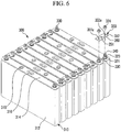
- FIG. 6 is a perspective view showing a battery module according to the second exemplary embodiment of the present invention.
- a battery module 300 includes a plurality of rechargeable batteries 310 having a positive electrode terminal 330 and a negative electrode terminal 340, and connecting members 350 that electrically connect the rechargeable batteries 310.
- the battery module 300 is formed by connecting the rechargeable batteries 310 in series.
- the rechargeable battery 310 is formed in a prismatic shape and includes a case 312, a cap plate 314 connected to an opening of the case 312, and the positive electrode terminal 330 and the negative electrode terminal 340 that protrude outside the case 312.
- a vent member 316 that is opened when the internal pressure increases and a sealing cap 318 that seals an electrolyte injection inlet are disposed on the cap plate 314.
- terminals 330 and 340 are disposed on the cap plate 314 to protrude outside the cap plate 314, and lower nuts 323 supporting the terminals 330 and 340 on the cap plate 314 are fitted on the terminals 330 and 340. Further, a gasket 321 for insulation is disposed between each lower nut 323 and the cap plate 314.
- the positive electrode terminal 330 and the negative electrode terminal 340 are formed substantially in a cylindrical shape, and the outer circumferential surfaces are threaded to fit nuts. Further, the positive electrode terminal 330 and the negative electrode terminal 340 are electrically connected with an electrode assembly inserted in the case 312.
- the positive electrode terminal 330 is made of aluminium and the negative electrode terminal 340 is made of copper.
- the connecting member 350 is disposed on the lower nut 323 and includes a first connecting bar 351 contacting the positive electrode terminal 330 and a second connecting bar 352 contacting the negative electrode terminal 340.
- the first connecting bar 351 is made of the same material as the positive electrode terminal 330, and a terminal hole 351a in which the positive electrode terminal 330 is inserted is formed through the first connecting bar 351.
- the second connecting bar 352 is made of the same material as the negative electrode terminal 340, and a terminal hole 352a in which the negative electrode terminal 340 is inserted is formed through the second connecting bar 352.
- the connecting member 350 is fixed to the terminals 330 and 340 by inserting the positive electrode terminal 330 and the negative electrode terminal 340 in the terminal holes 351a and 352a, respectively, and then fitting upper nuts 324 on the terminals 330 and 340.
- the connecting member 350 is formed in the same structure as the connecting member according to the first exemplary embodiment.
- Welding protrusions are formed at the first connecting bar 351 and the second connecting bar 352, and a welding portion 360 is formed at the connecting portion by overlapping and then bonding the welding protrusions, using friction stir welding.
- the portion contacting the positive electrode terminal 330 is made of the same material as the positive electrode terminal 330 and the portion contacting the negative electrode terminal 340 is made of the same material as the negative electrode terminal 340, it is possible to prevent corrosion between the connecting member 350 and the terminals 330 and 340. Further, since the first connecting bar 351 and the second connecting bar 352 are bonded by friction stir welding, it is possible to stably fix different metals.
Landscapes
- Chemical & Material Sciences (AREA)
- Chemical Kinetics & Catalysis (AREA)
- Electrochemistry (AREA)
- General Chemical & Material Sciences (AREA)
- Inorganic Chemistry (AREA)
- Connection Of Batteries Or Terminals (AREA)
- Pressure Welding/Diffusion-Bonding (AREA)
Claims (6)
- Module de batterie (100), comprenant :une pluralité de batteries rechargeables (110) formées sous une forme prismatique, comportant chacune un boîtier (112) et une plaque de protection (114) reliée à une ouverture du boîtier (112), etun élément de connexion (160) pour connecter électriquement une première borne d'électrode positive (130) d'une première batterie rechargeable (110) à une deuxième borne d'électrode négative (140) d'une deuxième batterie rechargeable (110), la première borne d'électrode (130) étant réalisée en aluminium et la deuxième borne d'électrode (140) étant réalisée en cuivre, et les première et deuxième bornes d'électrode (130, 140) faisant saillie à l'extérieur du boîtier (112),dans lequel :
l'élément de connexion (160) a la forme d'une plaque recouvrant la première borne d'électrode (130) et la deuxième borne d'électrode (140), et comprend :une première barre de connexion (161) connectée à la première borne d'électrode (130) de la première batterie rechargeable (110) et comprenant le même matériau que la première borne d'électrode (130),une deuxième barre de connexion (162) connectée à la deuxième borne d'électrode (140) de la deuxième batterie rechargeable (110) et comprenant le même matériau que la deuxième borne d'électrode (140), la deuxième barre de connexion (162) comprenant un matériau différent de celui de la première barre de connexion (161), etune partie de soudage (150) connectant la première barre de connexion (161) à la deuxième barre de connexion (162),caractérisé en ce que :la première barre de connexion (161, 221) a un profil étagé et comprend une première partie de soudage (161a, 212a) formée de façon à venir en contact avec la deuxième barre de connexion (162, 212) par soudage par friction malaxage, et une partie de corps,dans lequel la surface supérieure de la première barre de connexion (161) est étagée et la première partie de soudage (161a) a une épaisseur inférieure à celle de la partie de corps, les surfaces inférieures de la partie de corps et de la partie de soudage étant alignées l'une avec l'autre, etdans lequel la deuxième barre de connexion (162) a un profil étagé et comprend une partie de corps et une deuxième partie de soudage (162a) formée de façon à venir en contact avec la première partie de soudage (161a), la deuxième barre de connexion (162) étant agencée de telle sorte que les surfaces supérieures et inférieures des première et deuxième barres de connexion (161, 162) soient alignées les unes avec les autres. - Module de batterie (100) selon la revendication 1, dans lequel la partie de soudage (150) comprend une zone de noyau (152) comprenant un mélange des matériaux des première et deuxième barres de connexion (161, 162).
- Module de batterie (100) selon la revendication 2, dans lequel la zone de noyau est formée à l'intérieur des première et deuxième barres de connexion (161, 162).
- Module de batterie (100) selon l'une des revendications précédentes, dans lequel les première et deuxième barres de connexion (161, 162) comprennent chacune une partie de soudage de borne (165) au niveau de laquelle la première ou la deuxième barre de connexion (161, 162) est soudée à la première ou à la deuxième borne d'électrode (130, 140), respectivement.
- Module de batterie (100) selon l'une quelconque des revendications précédentes, dans lequel la partie de soudage (150) : comprend une rainure de soudage (151) formée dans la surface de l'élément de connexion (160) et/ou a une forme conique ou tronconique.
- Module de batterie (100) selon l'une des revendications précédentes, dans lequel la partie de soudage (150) comprend en outre au moins l'une parmi :une zone affectée de façon thermomécanique (154) autour de la zone de noyau (152), dans laquelle une déformation du matériau des première et deuxième barres de connexion (161, 162) est répartie selon un certain angle par rapport à la surface de la barre de connexion (160) ; etune zone affectée par la chaleur (156) autour de la zone affectée de façon thermomécanique (154).
Applications Claiming Priority (2)
| Application Number | Priority Date | Filing Date | Title |
|---|---|---|---|
| US24880609P | 2009-10-05 | 2009-10-05 | |
| US12/871,812 US9196890B2 (en) | 2009-10-05 | 2010-08-30 | Battery module with welded portion between terminals |
Publications (3)
| Publication Number | Publication Date |
|---|---|
| EP2339670A1 EP2339670A1 (fr) | 2011-06-29 |
| EP2339670B1 EP2339670B1 (fr) | 2012-11-14 |
| EP2339670B2 true EP2339670B2 (fr) | 2019-10-23 |
Family
ID=43823412
Family Applications (1)
| Application Number | Title | Priority Date | Filing Date |
|---|---|---|---|
| EP10175576.7A Active EP2339670B2 (fr) | 2009-10-05 | 2010-09-07 | Module de batterie |
Country Status (5)
| Country | Link |
|---|---|
| US (1) | US9196890B2 (fr) |
| EP (1) | EP2339670B2 (fr) |
| JP (1) | JP5250599B2 (fr) |
| KR (1) | KR101147173B1 (fr) |
| CN (1) | CN102034952B (fr) |
Families Citing this family (48)
| Publication number | Priority date | Publication date | Assignee | Title |
|---|---|---|---|---|
| CN103762330B (zh) * | 2009-02-02 | 2016-04-13 | 株式会社杰士汤浅国际 | 电池组及其制造方法、具备该电池组的车辆 |
| EP2441103B2 (fr) * | 2009-06-08 | 2018-09-12 | Auto-Kabel Management GmbH | Connecteur d'éléments de batterie |
| JP5528746B2 (ja) * | 2009-09-11 | 2014-06-25 | 三洋電機株式会社 | 組電池 |
| US8460818B2 (en) * | 2009-10-05 | 2013-06-11 | Samsung Sdi Co., Ltd. | Battery module |
| US8628875B2 (en) | 2010-04-16 | 2014-01-14 | Samsung Sdi Co., Ltd. | Battery module with multi-level connector |
| DE102010029970B4 (de) * | 2010-06-11 | 2021-06-02 | Vitesco Technologies GmbH | Batterie mit passivem Korrosionsschutz |
| JP5570383B2 (ja) * | 2010-10-15 | 2014-08-13 | 株式会社神戸製鋼所 | 導電性連結部材、導電性連結部材の製造方法、及び導電性連結部材が電極とされたバッテリ |
| USD644178S1 (en) * | 2010-11-26 | 2011-08-30 | Hitachi Vehicle Energy, Ltd. | Battery |
| FR2974317B1 (fr) * | 2011-04-20 | 2013-04-26 | Batscap Sa | Dispositif et procede de soudage par friction malaxage d'un ensemble de stockage d'energie electrique |
| US9118069B2 (en) * | 2011-05-10 | 2015-08-25 | GM Global Technology Operations LLC | Battery cell with integrated busbar |
| WO2012171071A1 (fr) * | 2011-06-15 | 2012-12-20 | Ev Engineering Limited | Interface d'adaptateur |
| WO2013001644A1 (fr) * | 2011-06-30 | 2013-01-03 | 日立ビークルエナジー株式会社 | Batterie assemblée |
| FR2979472B1 (fr) * | 2011-08-29 | 2013-08-23 | Batscap Sa | Connecteur dispose entre deux ensembles de stockage d'energie |
| FR2979473B1 (fr) | 2011-08-29 | 2013-08-16 | Batscap Sa | Ensemble de stockage d'energie longue duree a piece de connexion intermediaire |
| WO2013029483A1 (fr) * | 2011-08-29 | 2013-03-07 | 深圳市比亚迪汽车研发有限公司 | Pièce de connexion de batterie et groupe de batteries comprenant la pièce de connexion de batterie |
| JP5699296B2 (ja) * | 2011-09-12 | 2015-04-08 | 株式会社貴匠技研 | 金属材のかしめ構造及びこのかしめ構造を用いたバスバー |
| JP5672218B2 (ja) * | 2011-11-23 | 2015-02-18 | 株式会社デンソー | 組電池 |
| KR101294188B1 (ko) * | 2011-11-30 | 2013-08-08 | 기아자동차주식회사 | 차량용 고전압배터리의 안전구조 |
| KR101292276B1 (ko) * | 2011-12-07 | 2013-08-01 | 엘에스엠트론 주식회사 | 에너지 저장장치 모듈용 단자 연결 장치 |
| KR101324597B1 (ko) * | 2011-12-14 | 2013-11-06 | 주식회사 한라이비텍 | 폭발용접을 이용하는 이종 전극 배터리용 직렬 연결단자의 제작방법 및 그에 의해 제작된 직렬 연결단자 |
| KR101324593B1 (ko) * | 2011-12-14 | 2013-11-06 | 주식회사 한라이비텍 | 마찰교반용접을 이용하는 이종 전극 배터리용 직렬 연결단자의 제작방법 및 그에 의해 제작된 직렬 연결단자 |
| KR101324606B1 (ko) * | 2011-12-14 | 2013-11-06 | 주식회사 한라이비텍 | 레이저용접을 이용하는 이종 전극 배터리용 직렬 연결단자의 제작방법 및 그에 의해 제작된 직렬 연결단자 |
| US8927137B2 (en) * | 2012-05-01 | 2015-01-06 | Microsun Technologies Llc | Fail safe damage resistant battery matrix |
| US9318734B2 (en) * | 2012-05-21 | 2016-04-19 | Tyco Electronics Corporation | Bimetal buss bar assembly |
| EP2720320B1 (fr) * | 2012-10-12 | 2016-08-31 | Samsung SDI Co., Ltd. | Connecteur de cellules pour un système de batterie |
| US20140134471A1 (en) * | 2012-11-14 | 2014-05-15 | General Electric Company | Electrical interconnect and method of assembling a rechargeable battery |
| JP6249963B2 (ja) * | 2012-12-25 | 2017-12-20 | 株式会社Gsユアサ | 蓄電素子の製造方法及び蓄電素子アセンブリの製造方法 |
| JP5972454B2 (ja) * | 2013-04-16 | 2016-08-17 | 三菱電機株式会社 | バスバーおよびバスバーの製造方法 |
| EP2819217A1 (fr) | 2013-06-28 | 2014-12-31 | MAGNA STEYR Battery Systems GmbH & Co OG | Système de batterie doté d'un connecteur de cellules et procédé de fabrication |
| KR20150015153A (ko) | 2013-07-31 | 2015-02-10 | 주식회사 엘지화학 | 이종 금속의 전지모듈 접속부재를 포함하는 전지팩 |
| US9831482B2 (en) | 2013-09-06 | 2017-11-28 | Johnson Controls Technology Company | Battery module lid system and method |
| JP6210314B2 (ja) * | 2014-02-12 | 2017-10-11 | 株式会社オートネットワーク技術研究所 | 接続用部材および蓄電モジュール |
| CN105789923A (zh) * | 2014-12-23 | 2016-07-20 | 比亚迪股份有限公司 | 一种电池连接片及其制备方法以及电池连接组件、电池组、电池包和电动汽车 |
| JP6212028B2 (ja) * | 2014-12-26 | 2017-10-11 | トヨタ自動車株式会社 | 点摩擦撹拌接合構造 |
| US20160197323A1 (en) | 2015-01-05 | 2016-07-07 | Johnson Controls Technology Company | Battery module vent and handle configuration system and method |
| US10062931B2 (en) | 2015-04-22 | 2018-08-28 | Johnson Controls Technology Company | Welding process for battery module components |
| WO2016195063A1 (fr) * | 2015-06-03 | 2016-12-08 | 株式会社オートネットワーク技術研究所 | Procédé de production d'un élément de connexion et ce dernier |
| JP6590212B2 (ja) * | 2015-07-17 | 2019-10-16 | 株式会社オートネットワーク技術研究所 | 配線モジュール、及び蓄電モジュール |
| WO2017014049A1 (fr) * | 2015-07-17 | 2017-01-26 | 株式会社オートネットワーク技術研究所 | Module de câblage et module de stockage d'énergie |
| KR101623717B1 (ko) * | 2015-08-21 | 2016-05-24 | 대산전자(주) | 전기 연결 수단의 제조 방법 |
| KR102468334B1 (ko) | 2015-11-04 | 2022-11-16 | 삼성에스디아이 주식회사 | 이차 전지 모듈 |
| JP6741215B2 (ja) * | 2017-01-20 | 2020-08-19 | 株式会社オートネットワーク技術研究所 | 接続モジュール |
| US9997878B1 (en) * | 2017-03-01 | 2018-06-12 | GM Global Technology Operations LLC | Lightweight busbar for high voltage battery applications |
| US10547043B2 (en) * | 2017-07-18 | 2020-01-28 | Ford Global Technologies, Llc | Weld patterns for battery assembly joints |
| DE102018206231B3 (de) * | 2018-04-23 | 2019-09-19 | Triathlon Batterien Gmbh | Vorrichtung zum elektrischen Kontaktieren einer Leiterplatte an ein Batteriezellenverbundsystem und Einrichtung mit einer derartigen Vorrichtung und einem derartigen Batteriezellenverbundsystem |
| KR20200111498A (ko) * | 2019-03-19 | 2020-09-29 | 삼성에스디아이 주식회사 | 이차 전지 |
| JP2022024459A (ja) * | 2020-07-28 | 2022-02-09 | 株式会社不二越 | 二次電池用通電部品およびその製造方法 |
| KR102863874B1 (ko) * | 2023-05-23 | 2025-09-24 | (주)상은 | 버스바 결합구조 |
Citations (11)
| Publication number | Priority date | Publication date | Assignee | Title |
|---|---|---|---|---|
| WO1993010935A1 (fr) † | 1991-12-06 | 1993-06-10 | The Welding Institute | Ameliorations relatives au soudage par friction |
| EP1160893A2 (fr) † | 2000-05-24 | 2001-12-05 | Ngk Insulators, Ltd. | Accumulateur au lithium et son procédé de montage |
| US20020046864A1 (en) † | 2000-04-28 | 2002-04-25 | Bellino Joseph P. | Method of joining conductive materials |
| JP2002358945A (ja) † | 2000-11-15 | 2002-12-13 | Ngk Insulators Ltd | リチウム二次単電池の接続構造体 |
| US20060088761A1 (en) † | 2004-10-26 | 2006-04-27 | Nissan Motor Co., Ltd. | Battery module |
| US20060255764A1 (en) † | 2005-05-16 | 2006-11-16 | Kyu-Woong Cho | Battery module |
| US20090123830A1 (en) † | 2005-07-05 | 2009-05-14 | Masahiko Kato | Inter-battery connection device |
| JP4326214B2 (ja) † | 2002-12-25 | 2009-09-02 | 三菱重工業株式会社 | ボビンツールを用いた摩擦攪拌接合装置とその接合方法 |
| US20090223940A1 (en) † | 2004-08-09 | 2009-09-10 | Nec Corporation | Different metallic thin plates welding method, bimetallic thin plates jointing element, electric device, and electric device assembly |
| DE202009012647U1 (de) † | 2009-09-21 | 2009-11-26 | Auto-Kabel Managementgesellschaft Mbh | Batteriezellenverbinder |
| WO2010142679A1 (fr) † | 2009-06-08 | 2010-12-16 | Auto-Kabel Managementgesellschaft Mbh | Connecteur d'éléments de batterie |
Family Cites Families (13)
| Publication number | Priority date | Publication date | Assignee | Title |
|---|---|---|---|---|
| JP3343890B2 (ja) | 1997-10-13 | 2002-11-11 | トヨタ自動車株式会社 | バッテリーホルダ用接続プレート |
| JP5128739B2 (ja) | 2001-09-03 | 2013-01-23 | 三洋電機株式会社 | 電池パックの製造方法 |
| JP5151027B2 (ja) | 2004-12-14 | 2013-02-27 | トヨタ自動車株式会社 | 組電池 |
| US20060127754A1 (en) | 2004-12-14 | 2006-06-15 | Toyota Jidosha Kabushiki Kaisha. | Battery pack |
| JP5005183B2 (ja) | 2005-04-14 | 2012-08-22 | パナソニック株式会社 | 電池間接続構造 |
| KR100778511B1 (ko) * | 2006-09-11 | 2007-11-22 | 삼성에스디아이 주식회사 | 이차 전지 모듈 |
| JP2008123800A (ja) | 2006-11-10 | 2008-05-29 | Sanyo Electric Co Ltd | 電池の接続構造及び接続方法 |
| CN101315990B (zh) | 2007-05-29 | 2010-06-09 | 上海比亚迪有限公司 | 一种电池组 |
| KR100946834B1 (ko) * | 2007-12-13 | 2010-03-09 | 현대자동차일본기술연구소 | 전지 팩 및 그의 제조방법 |
| US20090159354A1 (en) * | 2007-12-25 | 2009-06-25 | Wenfeng Jiang | Battery system having interconnected battery packs each having multiple electrochemical storage cells |
| DE202010012555U1 (de) | 2009-06-08 | 2010-11-18 | Auto-Kabel Managementgesellschaft Mbh | Batteriezellenverbinder mit Z-Schlag |
| DE102009024513A1 (de) | 2009-06-08 | 2010-12-09 | Auto-Kabel Managementgesellschaft Mbh | Batteriezellenverbinder |
| US8460818B2 (en) | 2009-10-05 | 2013-06-11 | Samsung Sdi Co., Ltd. | Battery module |
-
2010
- 2010-08-30 US US12/871,812 patent/US9196890B2/en active Active
- 2010-09-07 EP EP10175576.7A patent/EP2339670B2/fr active Active
- 2010-09-08 KR KR1020100087996A patent/KR101147173B1/ko active Active
- 2010-09-21 CN CN201010291578.9A patent/CN102034952B/zh active Active
- 2010-10-05 JP JP2010225773A patent/JP5250599B2/ja active Active
Patent Citations (11)
| Publication number | Priority date | Publication date | Assignee | Title |
|---|---|---|---|---|
| WO1993010935A1 (fr) † | 1991-12-06 | 1993-06-10 | The Welding Institute | Ameliorations relatives au soudage par friction |
| US20020046864A1 (en) † | 2000-04-28 | 2002-04-25 | Bellino Joseph P. | Method of joining conductive materials |
| EP1160893A2 (fr) † | 2000-05-24 | 2001-12-05 | Ngk Insulators, Ltd. | Accumulateur au lithium et son procédé de montage |
| JP2002358945A (ja) † | 2000-11-15 | 2002-12-13 | Ngk Insulators Ltd | リチウム二次単電池の接続構造体 |
| JP4326214B2 (ja) † | 2002-12-25 | 2009-09-02 | 三菱重工業株式会社 | ボビンツールを用いた摩擦攪拌接合装置とその接合方法 |
| US20090223940A1 (en) † | 2004-08-09 | 2009-09-10 | Nec Corporation | Different metallic thin plates welding method, bimetallic thin plates jointing element, electric device, and electric device assembly |
| US20060088761A1 (en) † | 2004-10-26 | 2006-04-27 | Nissan Motor Co., Ltd. | Battery module |
| US20060255764A1 (en) † | 2005-05-16 | 2006-11-16 | Kyu-Woong Cho | Battery module |
| US20090123830A1 (en) † | 2005-07-05 | 2009-05-14 | Masahiko Kato | Inter-battery connection device |
| WO2010142679A1 (fr) † | 2009-06-08 | 2010-12-16 | Auto-Kabel Managementgesellschaft Mbh | Connecteur d'éléments de batterie |
| DE202009012647U1 (de) † | 2009-09-21 | 2009-11-26 | Auto-Kabel Managementgesellschaft Mbh | Batteriezellenverbinder |
Non-Patent Citations (24)
| Title |
|---|
| Affidavit of Mr. Taeweon Heo, Senior Manager, legal & IP Team, Samsung SDI Co., Ltd., regarding document PD21 † |
| Affidavit of Mr. Taeweon Heo, Senior Manager, legal & IP Team, Samsung SDI Co., Ltd., regarding documents PD16 - 19 † |
| Annual salary contract between SBLiMotive and Mr. Hyo-Seob Kim † |
| Annual salary contract between SBLiMotive and Mr. Sang-Won Byun † |
| Annual salary contract between SBLiMotive and Mr. Sung-Bae Kim † |
| Annual Salary contract between SBLiMotive and Mr. Yong-Sam Kim † |
| Certified translation into English of D5 † |
| Confirmation receipt of filing of the provisional application US/871,812 † |
| Decision T0062/05 of the Technical Boards of Appeal at the European Patent Office † |
| Declaration and Power of Attorney as well as an assignment for Patent Application, Docket No. 64480/P849 † |
| English translation of parts of PD16 † |
| English translation of parts of PD18 † |
| English translation of parts of PD19 † |
| English translation of parts PD17 † |
| English Wikipedia page "Friction stir welding" edited on 24.07.2009 † |
| Excerpt of the company regulations of SB LiMotive Co., Ltd. including a partial translation of the excerpt into English † |
| Excerpt of the European Patent Register relating to the European family document of D2 † |
| German priority application No. 10 2009 024 513.8, filed 08.06.2009 † |
| German priority application No. 10 2010 015 810.0, filed 20.04.2010 † |
| German priority application No. 20 2009 012 647.1, filed 21.09.2009 † |
| Letter of Declaration of Mr. Yung Kwang Lee, Legal Counsel, Samsung SDI Co. Ltd., dated Dec. 10, 2014 † |
| Letter of Declaration of Mr.Taeweon HEO, Senior Manager, legal & IP Team, Samsung SDI Co., Ltd., dated Oct. 9, 2015 † |
| Mashine translation of D10 † |
| Patent System record: inventors information (in Korean) and invention history (in Korean with partial translation into English) † |
Also Published As
| Publication number | Publication date |
|---|---|
| US20110081568A1 (en) | 2011-04-07 |
| JP2011082164A (ja) | 2011-04-21 |
| KR101147173B1 (ko) | 2012-05-25 |
| CN102034952B (zh) | 2014-06-04 |
| KR20110037844A (ko) | 2011-04-13 |
| CN102034952A (zh) | 2011-04-27 |
| JP5250599B2 (ja) | 2013-07-31 |
| EP2339670A1 (fr) | 2011-06-29 |
| EP2339670B1 (fr) | 2012-11-14 |
| US9196890B2 (en) | 2015-11-24 |
Similar Documents
| Publication | Publication Date | Title |
|---|---|---|
| EP2339670B1 (fr) | Module de batterie comprenant un élément de connexion composé d'une première et d'une deuxième barre de connexion | |
| EP2312674B1 (fr) | Interconnecteur de batteries | |
| US8628875B2 (en) | Battery module with multi-level connector | |
| EP3343691B1 (fr) | Module de batterie | |
| KR101097227B1 (ko) | 배터리모듈 및 그 제조방법 | |
| KR102397762B1 (ko) | 양극 단자 일체형 캡 플레이트를 갖는 이차 전지 | |
| US8211565B2 (en) | Secondary battery for medium and large size battery module | |
| KR102454791B1 (ko) | 양극 단자와 멤브레인 일체형 캡 플레이트를 갖는 이차 전지 | |
| KR20150144600A (ko) | 이차 전지 | |
| EP1779962A1 (fr) | Méthode de soudure de fines plaques de différents métaux, corps jointif de fines plaques de différents métaux, le dispositif électrique et le montage électrique du dispositif | |
| KR101649131B1 (ko) | 연결부재를 갖는 전지 모듈 |
Legal Events
| Date | Code | Title | Description |
|---|---|---|---|
| PUAI | Public reference made under article 153(3) epc to a published international application that has entered the european phase |
Free format text: ORIGINAL CODE: 0009012 |
|
| 17P | Request for examination filed |
Effective date: 20100907 |
|
| AK | Designated contracting states |
Kind code of ref document: A1 Designated state(s): AL AT BE BG CH CY CZ DE DK EE ES FI FR GB GR HR HU IE IS IT LI LT LU LV MC MK MT NL NO PL PT RO SE SI SK SM TR |
|
| AX | Request for extension of the european patent |
Extension state: BA ME RS |
|
| GRAP | Despatch of communication of intention to grant a patent |
Free format text: ORIGINAL CODE: EPIDOSNIGR1 |
|
| GRAS | Grant fee paid |
Free format text: ORIGINAL CODE: EPIDOSNIGR3 |
|
| GRAA | (expected) grant |
Free format text: ORIGINAL CODE: 0009210 |
|
| AK | Designated contracting states |
Kind code of ref document: B1 Designated state(s): AL AT BE BG CH CY CZ DE DK EE ES FI FR GB GR HR HU IE IS IT LI LT LU LV MC MK MT NL NO PL PT RO SE SI SK SM TR |
|
| REG | Reference to a national code |
Ref country code: GB Ref legal event code: FG4D |
|
| RIN1 | Information on inventor provided before grant (corrected) |
Inventor name: BYUN, SANG-WON Inventor name: KIM, YONG-SAM Inventor name: KIM, SUNG-BAE Inventor name: KIM, HYO-SEOB |
|
| REG | Reference to a national code |
Ref country code: CH Ref legal event code: EP Ref country code: AT Ref legal event code: REF Ref document number: 584384 Country of ref document: AT Kind code of ref document: T Effective date: 20121115 |
|
| RIN2 | Information on inventor provided after grant (corrected) |
Inventor name: KIM, SUNG-BAE Inventor name: KIM, HYO-SEOB Inventor name: KIM, YONG-SAM Inventor name: BYUN, SANG-WON |
|
| REG | Reference to a national code |
Ref country code: IE Ref legal event code: FG4D |
|
| REG | Reference to a national code |
Ref country code: DE Ref legal event code: R096 Ref document number: 602010003595 Country of ref document: DE Effective date: 20130110 |
|
| REG | Reference to a national code |
Ref country code: FR Ref legal event code: TQ Owner name: SAMSUNG SDI CO., LTD., KR Effective date: 20130218 Ref country code: FR Ref legal event code: TQ Owner name: ROBERT BOSCH GMBH, DE Effective date: 20130218 |
|
| REG | Reference to a national code |
Ref country code: NL Ref legal event code: VDEP Effective date: 20121114 |
|
| REG | Reference to a national code |
Ref country code: AT Ref legal event code: MK05 Ref document number: 584384 Country of ref document: AT Kind code of ref document: T Effective date: 20121114 |
|
| REG | Reference to a national code |
Ref country code: LT Ref legal event code: MG4D |
|
| PG25 | Lapsed in a contracting state [announced via postgrant information from national office to epo] |
Ref country code: HR Free format text: LAPSE BECAUSE OF FAILURE TO SUBMIT A TRANSLATION OF THE DESCRIPTION OR TO PAY THE FEE WITHIN THE PRESCRIBED TIME-LIMIT Effective date: 20121114 Ref country code: NO Free format text: LAPSE BECAUSE OF FAILURE TO SUBMIT A TRANSLATION OF THE DESCRIPTION OR TO PAY THE FEE WITHIN THE PRESCRIBED TIME-LIMIT Effective date: 20130214 Ref country code: ES Free format text: LAPSE BECAUSE OF FAILURE TO SUBMIT A TRANSLATION OF THE DESCRIPTION OR TO PAY THE FEE WITHIN THE PRESCRIBED TIME-LIMIT Effective date: 20130225 Ref country code: FI Free format text: LAPSE BECAUSE OF FAILURE TO SUBMIT A TRANSLATION OF THE DESCRIPTION OR TO PAY THE FEE WITHIN THE PRESCRIBED TIME-LIMIT Effective date: 20121114 Ref country code: SE Free format text: LAPSE BECAUSE OF FAILURE TO SUBMIT A TRANSLATION OF THE DESCRIPTION OR TO PAY THE FEE WITHIN THE PRESCRIBED TIME-LIMIT Effective date: 20121114 Ref country code: LT Free format text: LAPSE BECAUSE OF FAILURE TO SUBMIT A TRANSLATION OF THE DESCRIPTION OR TO PAY THE FEE WITHIN THE PRESCRIBED TIME-LIMIT Effective date: 20121114 |
|
| REG | Reference to a national code |
Ref country code: GB Ref legal event code: 732E Free format text: REGISTERED BETWEEN 20130425 AND 20130501 |
|
| PG25 | Lapsed in a contracting state [announced via postgrant information from national office to epo] |
Ref country code: PL Free format text: LAPSE BECAUSE OF FAILURE TO SUBMIT A TRANSLATION OF THE DESCRIPTION OR TO PAY THE FEE WITHIN THE PRESCRIBED TIME-LIMIT Effective date: 20121114 Ref country code: SI Free format text: LAPSE BECAUSE OF FAILURE TO SUBMIT A TRANSLATION OF THE DESCRIPTION OR TO PAY THE FEE WITHIN THE PRESCRIBED TIME-LIMIT Effective date: 20121114 Ref country code: PT Free format text: LAPSE BECAUSE OF FAILURE TO SUBMIT A TRANSLATION OF THE DESCRIPTION OR TO PAY THE FEE WITHIN THE PRESCRIBED TIME-LIMIT Effective date: 20130314 Ref country code: BE Free format text: LAPSE BECAUSE OF FAILURE TO SUBMIT A TRANSLATION OF THE DESCRIPTION OR TO PAY THE FEE WITHIN THE PRESCRIBED TIME-LIMIT Effective date: 20121114 Ref country code: GR Free format text: LAPSE BECAUSE OF FAILURE TO SUBMIT A TRANSLATION OF THE DESCRIPTION OR TO PAY THE FEE WITHIN THE PRESCRIBED TIME-LIMIT Effective date: 20130215 Ref country code: LV Free format text: LAPSE BECAUSE OF FAILURE TO SUBMIT A TRANSLATION OF THE DESCRIPTION OR TO PAY THE FEE WITHIN THE PRESCRIBED TIME-LIMIT Effective date: 20121114 |
|
| PG25 | Lapsed in a contracting state [announced via postgrant information from national office to epo] |
Ref country code: AT Free format text: LAPSE BECAUSE OF FAILURE TO SUBMIT A TRANSLATION OF THE DESCRIPTION OR TO PAY THE FEE WITHIN THE PRESCRIBED TIME-LIMIT Effective date: 20121114 |
|
| PG25 | Lapsed in a contracting state [announced via postgrant information from national office to epo] |
Ref country code: SK Free format text: LAPSE BECAUSE OF FAILURE TO SUBMIT A TRANSLATION OF THE DESCRIPTION OR TO PAY THE FEE WITHIN THE PRESCRIBED TIME-LIMIT Effective date: 20121114 Ref country code: CZ Free format text: LAPSE BECAUSE OF FAILURE TO SUBMIT A TRANSLATION OF THE DESCRIPTION OR TO PAY THE FEE WITHIN THE PRESCRIBED TIME-LIMIT Effective date: 20121114 Ref country code: BG Free format text: LAPSE BECAUSE OF FAILURE TO SUBMIT A TRANSLATION OF THE DESCRIPTION OR TO PAY THE FEE WITHIN THE PRESCRIBED TIME-LIMIT Effective date: 20130214 Ref country code: DK Free format text: LAPSE BECAUSE OF FAILURE TO SUBMIT A TRANSLATION OF THE DESCRIPTION OR TO PAY THE FEE WITHIN THE PRESCRIBED TIME-LIMIT Effective date: 20121114 Ref country code: EE Free format text: LAPSE BECAUSE OF FAILURE TO SUBMIT A TRANSLATION OF THE DESCRIPTION OR TO PAY THE FEE WITHIN THE PRESCRIBED TIME-LIMIT Effective date: 20121114 |
|
| REG | Reference to a national code |
Ref country code: DE Ref legal event code: R081 Ref document number: 602010003595 Country of ref document: DE Owner name: SAMSUNG SDI CO., LTD., YONGIN-SI, KR Free format text: FORMER OWNER: SB LIMOTIVE CO., LTD., YONGIN, KYONGGI, KR Effective date: 20130612 Ref country code: DE Ref legal event code: R081 Ref document number: 602010003595 Country of ref document: DE Owner name: ROBERT BOSCH GMBH, DE Free format text: FORMER OWNER: SB LIMOTIVE CO., LTD., YONGIN, KYONGGI, KR Effective date: 20130612 Ref country code: DE Ref legal event code: R081 Ref document number: 602010003595 Country of ref document: DE Owner name: SAMSUNG SDI CO., LTD., KR Free format text: FORMER OWNER: SB LIMOTIVE CO., LTD., YONGIN, KR Effective date: 20130612 Ref country code: DE Ref legal event code: R081 Ref document number: 602010003595 Country of ref document: DE Owner name: ROBERT BOSCH GMBH, DE Free format text: FORMER OWNER: SB LIMOTIVE CO., LTD., YONGIN, KR Effective date: 20130612 |
|
| PLBI | Opposition filed |
Free format text: ORIGINAL CODE: 0009260 |
|
| PLBI | Opposition filed |
Free format text: ORIGINAL CODE: 0009260 |
|
| PG25 | Lapsed in a contracting state [announced via postgrant information from national office to epo] |
Ref country code: IT Free format text: LAPSE BECAUSE OF FAILURE TO SUBMIT A TRANSLATION OF THE DESCRIPTION OR TO PAY THE FEE WITHIN THE PRESCRIBED TIME-LIMIT Effective date: 20121114 Ref country code: NL Free format text: LAPSE BECAUSE OF FAILURE TO SUBMIT A TRANSLATION OF THE DESCRIPTION OR TO PAY THE FEE WITHIN THE PRESCRIBED TIME-LIMIT Effective date: 20121114 Ref country code: RO Free format text: LAPSE BECAUSE OF FAILURE TO SUBMIT A TRANSLATION OF THE DESCRIPTION OR TO PAY THE FEE WITHIN THE PRESCRIBED TIME-LIMIT Effective date: 20121114 |
|
| PLAX | Notice of opposition and request to file observation + time limit sent |
Free format text: ORIGINAL CODE: EPIDOSNOBS2 |
|
| 26 | Opposition filed |
Opponent name: ELRINGKLINGER AG Effective date: 20130812 |
|
| 26 | Opposition filed |
Opponent name: MAGNA STEYR BATTERY SYSTEMS GMBH & CO OG Effective date: 20130812 |
|
| REG | Reference to a national code |
Ref country code: DE Ref legal event code: R026 Ref document number: 602010003595 Country of ref document: DE Effective date: 20130812 |
|
| PG25 | Lapsed in a contracting state [announced via postgrant information from national office to epo] |
Ref country code: CY Free format text: LAPSE BECAUSE OF FAILURE TO SUBMIT A TRANSLATION OF THE DESCRIPTION OR TO PAY THE FEE WITHIN THE PRESCRIBED TIME-LIMIT Effective date: 20121114 |
|
| PLAF | Information modified related to communication of a notice of opposition and request to file observations + time limit |
Free format text: ORIGINAL CODE: EPIDOSCOBS2 |
|
| PLAB | Opposition data, opponent's data or that of the opponent's representative modified |
Free format text: ORIGINAL CODE: 0009299OPPO |
|
| R26 | Opposition filed (corrected) |
Opponent name: MAGNA STEYR BATTERY SYSTEMS GMBH & CO OG Effective date: 20130812 |
|
| PLBB | Reply of patent proprietor to notice(s) of opposition received |
Free format text: ORIGINAL CODE: EPIDOSNOBS3 |
|
| PG25 | Lapsed in a contracting state [announced via postgrant information from national office to epo] |
Ref country code: MC Free format text: LAPSE BECAUSE OF FAILURE TO SUBMIT A TRANSLATION OF THE DESCRIPTION OR TO PAY THE FEE WITHIN THE PRESCRIBED TIME-LIMIT Effective date: 20121114 |
|
| REG | Reference to a national code |
Ref country code: IE Ref legal event code: MM4A |
|
| PG25 | Lapsed in a contracting state [announced via postgrant information from national office to epo] |
Ref country code: IE Free format text: LAPSE BECAUSE OF NON-PAYMENT OF DUE FEES Effective date: 20130907 |
|
| REG | Reference to a national code |
Ref country code: CH Ref legal event code: PL |
|
| PLBP | Opposition withdrawn |
Free format text: ORIGINAL CODE: 0009264 |
|
| PG25 | Lapsed in a contracting state [announced via postgrant information from national office to epo] |
Ref country code: SM Free format text: LAPSE BECAUSE OF FAILURE TO SUBMIT A TRANSLATION OF THE DESCRIPTION OR TO PAY THE FEE WITHIN THE PRESCRIBED TIME-LIMIT Effective date: 20121114 |
|
| PG25 | Lapsed in a contracting state [announced via postgrant information from national office to epo] |
Ref country code: TR Free format text: LAPSE BECAUSE OF FAILURE TO SUBMIT A TRANSLATION OF THE DESCRIPTION OR TO PAY THE FEE WITHIN THE PRESCRIBED TIME-LIMIT Effective date: 20121114 Ref country code: MT Free format text: LAPSE BECAUSE OF FAILURE TO SUBMIT A TRANSLATION OF THE DESCRIPTION OR TO PAY THE FEE WITHIN THE PRESCRIBED TIME-LIMIT Effective date: 20121114 |
|
| PG25 | Lapsed in a contracting state [announced via postgrant information from national office to epo] |
Ref country code: HU Free format text: LAPSE BECAUSE OF FAILURE TO SUBMIT A TRANSLATION OF THE DESCRIPTION OR TO PAY THE FEE WITHIN THE PRESCRIBED TIME-LIMIT; INVALID AB INITIO Effective date: 20100907 Ref country code: MK Free format text: LAPSE BECAUSE OF FAILURE TO SUBMIT A TRANSLATION OF THE DESCRIPTION OR TO PAY THE FEE WITHIN THE PRESCRIBED TIME-LIMIT Effective date: 20121114 Ref country code: CH Free format text: LAPSE BECAUSE OF NON-PAYMENT OF DUE FEES Effective date: 20140930 Ref country code: LI Free format text: LAPSE BECAUSE OF NON-PAYMENT OF DUE FEES Effective date: 20140930 Ref country code: LU Free format text: LAPSE BECAUSE OF NON-PAYMENT OF DUE FEES Effective date: 20130907 |
|
| REG | Reference to a national code |
Ref country code: FR Ref legal event code: PLFP Year of fee payment: 6 |
|
| RIC2 | Information provided on ipc code assigned after grant |
Ipc: H01M 2/30 20060101ALI20151130BHEP Ipc: H01M 2/20 20060101AFI20151130BHEP |
|
| APBM | Appeal reference recorded |
Free format text: ORIGINAL CODE: EPIDOSNREFNO |
|
| APBP | Date of receipt of notice of appeal recorded |
Free format text: ORIGINAL CODE: EPIDOSNNOA2O |
|
| APAH | Appeal reference modified |
Free format text: ORIGINAL CODE: EPIDOSCREFNO |
|
| APBQ | Date of receipt of statement of grounds of appeal recorded |
Free format text: ORIGINAL CODE: EPIDOSNNOA3O |
|
| PG25 | Lapsed in a contracting state [announced via postgrant information from national office to epo] |
Ref country code: IS Free format text: LAPSE BECAUSE OF FAILURE TO SUBMIT A TRANSLATION OF THE DESCRIPTION OR TO PAY THE FEE WITHIN THE PRESCRIBED TIME-LIMIT Effective date: 20121114 |
|
| REG | Reference to a national code |
Ref country code: FR Ref legal event code: PLFP Year of fee payment: 7 |
|
| REG | Reference to a national code |
Ref country code: FR Ref legal event code: PLFP Year of fee payment: 8 |
|
| APBU | Appeal procedure closed |
Free format text: ORIGINAL CODE: EPIDOSNNOA9O |
|
| PLAY | Examination report in opposition despatched + time limit |
Free format text: ORIGINAL CODE: EPIDOSNORE2 |
|
| PLBC | Reply to examination report in opposition received |
Free format text: ORIGINAL CODE: EPIDOSNORE3 |
|
| PLAY | Examination report in opposition despatched + time limit |
Free format text: ORIGINAL CODE: EPIDOSNORE2 |
|
| REG | Reference to a national code |
Ref country code: FR Ref legal event code: PLFP Year of fee payment: 9 |
|
| PLBC | Reply to examination report in opposition received |
Free format text: ORIGINAL CODE: EPIDOSNORE3 |
|
| PG25 | Lapsed in a contracting state [announced via postgrant information from national office to epo] |
Ref country code: AL Free format text: LAPSE BECAUSE OF FAILURE TO SUBMIT A TRANSLATION OF THE DESCRIPTION OR TO PAY THE FEE WITHIN THE PRESCRIBED TIME-LIMIT Effective date: 20121114 |
|
| PUAH | Patent maintained in amended form |
Free format text: ORIGINAL CODE: 0009272 |
|
| STAA | Information on the status of an ep patent application or granted ep patent |
Free format text: STATUS: PATENT MAINTAINED AS AMENDED |
|
| 27A | Patent maintained in amended form |
Effective date: 20191023 |
|
| AK | Designated contracting states |
Kind code of ref document: B2 Designated state(s): AL AT BE BG CH CY CZ DE DK EE ES FI FR GB GR HR HU IE IS IT LI LT LU LV MC MK MT NL NO PL PT RO SE SI SK SM TR |
|
| REG | Reference to a national code |
Ref country code: DE Ref legal event code: R102 Ref document number: 602010003595 Country of ref document: DE |
|
| REG | Reference to a national code |
Ref country code: DE Ref legal event code: R079 Ref document number: 602010003595 Country of ref document: DE Free format text: PREVIOUS MAIN CLASS: H01M0002200000 Ipc: H01M0050500000 |
|
| P01 | Opt-out of the competence of the unified patent court (upc) registered |
Effective date: 20230528 |
|
| PGFP | Annual fee paid to national office [announced via postgrant information from national office to epo] |
Ref country code: DE Payment date: 20250902 Year of fee payment: 16 |
|
| PGFP | Annual fee paid to national office [announced via postgrant information from national office to epo] |
Ref country code: GB Payment date: 20250904 Year of fee payment: 16 |
|
| PGFP | Annual fee paid to national office [announced via postgrant information from national office to epo] |
Ref country code: FR Payment date: 20250908 Year of fee payment: 16 |