EP2339669B1 - Élément de connexion de piles et module de piles l'utilisant - Google Patents
Élément de connexion de piles et module de piles l'utilisant Download PDFInfo
- Publication number
- EP2339669B1 EP2339669B1 EP10799599A EP10799599A EP2339669B1 EP 2339669 B1 EP2339669 B1 EP 2339669B1 EP 10799599 A EP10799599 A EP 10799599A EP 10799599 A EP10799599 A EP 10799599A EP 2339669 B1 EP2339669 B1 EP 2339669B1
- Authority
- EP
- European Patent Office
- Prior art keywords
- battery
- batteries
- conductive path
- path portion
- main conductive
- Prior art date
- Legal status (The legal status is an assumption and is not a legal conclusion. Google has not performed a legal analysis and makes no representation as to the accuracy of the status listed.)
- Active
Links
- 239000000463 material Substances 0.000 description 16
- 239000007789 gas Substances 0.000 description 11
- 229910052751 metal Inorganic materials 0.000 description 10
- 239000002184 metal Substances 0.000 description 10
- OKTJSMMVPCPJKN-UHFFFAOYSA-N Carbon Chemical compound [C] OKTJSMMVPCPJKN-UHFFFAOYSA-N 0.000 description 8
- PXHVJJICTQNCMI-UHFFFAOYSA-N Nickel Chemical compound [Ni] PXHVJJICTQNCMI-UHFFFAOYSA-N 0.000 description 8
- 238000005192 partition Methods 0.000 description 8
- -1 polytetrafluoroethylene Polymers 0.000 description 6
- HBBGRARXTFLTSG-UHFFFAOYSA-N Lithium ion Chemical compound [Li+] HBBGRARXTFLTSG-UHFFFAOYSA-N 0.000 description 5
- 230000015556 catabolic process Effects 0.000 description 5
- 238000006731 degradation reaction Methods 0.000 description 5
- 238000013461 design Methods 0.000 description 5
- 229910001416 lithium ion Inorganic materials 0.000 description 5
- 239000000758 substrate Substances 0.000 description 5
- 229910052782 aluminium Inorganic materials 0.000 description 4
- 229910052759 nickel Inorganic materials 0.000 description 4
- 229920005989 resin Polymers 0.000 description 4
- 239000011347 resin Substances 0.000 description 4
- 229910052802 copper Inorganic materials 0.000 description 3
- 239000010949 copper Substances 0.000 description 3
- 239000011255 nonaqueous electrolyte Substances 0.000 description 3
- 238000007747 plating Methods 0.000 description 3
- 238000007789 sealing Methods 0.000 description 3
- RYGMFSIKBFXOCR-UHFFFAOYSA-N Copper Chemical compound [Cu] RYGMFSIKBFXOCR-UHFFFAOYSA-N 0.000 description 2
- KMTRUDSVKNLOMY-UHFFFAOYSA-N Ethylene carbonate Chemical compound O=C1OCCO1 KMTRUDSVKNLOMY-UHFFFAOYSA-N 0.000 description 2
- 229910001030 Iron–nickel alloy Inorganic materials 0.000 description 2
- XAGFODPZIPBFFR-UHFFFAOYSA-N aluminium Chemical compound [Al] XAGFODPZIPBFFR-UHFFFAOYSA-N 0.000 description 2
- 239000011230 binding agent Substances 0.000 description 2
- 229910052799 carbon Inorganic materials 0.000 description 2
- 150000001875 compounds Chemical class 0.000 description 2
- 239000006258 conductive agent Substances 0.000 description 2
- 239000008151 electrolyte solution Substances 0.000 description 2
- JBTWLSYIZRCDFO-UHFFFAOYSA-N ethyl methyl carbonate Chemical compound CCOC(=O)OC JBTWLSYIZRCDFO-UHFFFAOYSA-N 0.000 description 2
- 238000002844 melting Methods 0.000 description 2
- 230000008018 melting Effects 0.000 description 2
- 239000003960 organic solvent Substances 0.000 description 2
- 239000007774 positive electrode material Substances 0.000 description 2
- ZZXUZKXVROWEIF-UHFFFAOYSA-N 1,2-butylene carbonate Chemical compound CCC1COC(=O)O1 ZZXUZKXVROWEIF-UHFFFAOYSA-N 0.000 description 1
- VAYTZRYEBVHVLE-UHFFFAOYSA-N 1,3-dioxol-2-one Chemical compound O=C1OC=CO1 VAYTZRYEBVHVLE-UHFFFAOYSA-N 0.000 description 1
- OIFBSDVPJOWBCH-UHFFFAOYSA-N Diethyl carbonate Chemical compound CCOC(=O)OCC OIFBSDVPJOWBCH-UHFFFAOYSA-N 0.000 description 1
- 229910000552 LiCF3SO3 Inorganic materials 0.000 description 1
- 229910032387 LiCoO2 Inorganic materials 0.000 description 1
- 229910003005 LiNiO2 Inorganic materials 0.000 description 1
- 229910001290 LiPF6 Inorganic materials 0.000 description 1
- WHXSMMKQMYFTQS-UHFFFAOYSA-N Lithium Chemical compound [Li] WHXSMMKQMYFTQS-UHFFFAOYSA-N 0.000 description 1
- 239000002033 PVDF binder Substances 0.000 description 1
- 239000004952 Polyamide Substances 0.000 description 1
- 239000004698 Polyethylene Substances 0.000 description 1
- 239000004642 Polyimide Substances 0.000 description 1
- 239000004743 Polypropylene Substances 0.000 description 1
- XUIMIQQOPSSXEZ-UHFFFAOYSA-N Silicon Chemical compound [Si] XUIMIQQOPSSXEZ-UHFFFAOYSA-N 0.000 description 1
- ATJFFYVFTNAWJD-UHFFFAOYSA-N Tin Chemical compound [Sn] ATJFFYVFTNAWJD-UHFFFAOYSA-N 0.000 description 1
- RTAQQCXQSZGOHL-UHFFFAOYSA-N Titanium Chemical compound [Ti] RTAQQCXQSZGOHL-UHFFFAOYSA-N 0.000 description 1
- 230000002159 abnormal effect Effects 0.000 description 1
- 239000006230 acetylene black Substances 0.000 description 1
- 239000004760 aramid Substances 0.000 description 1
- 229920003235 aromatic polyamide Polymers 0.000 description 1
- 229910021383 artificial graphite Inorganic materials 0.000 description 1
- OJIJEKBXJYRIBZ-UHFFFAOYSA-N cadmium nickel Chemical compound [Ni].[Cd] OJIJEKBXJYRIBZ-UHFFFAOYSA-N 0.000 description 1
- 239000006229 carbon black Substances 0.000 description 1
- 235000019241 carbon black Nutrition 0.000 description 1
- 239000003575 carbonaceous material Substances 0.000 description 1
- 239000006231 channel black Substances 0.000 description 1
- 238000004891 communication Methods 0.000 description 1
- 238000011161 development Methods 0.000 description 1
- IEJIGPNLZYLLBP-UHFFFAOYSA-N dimethyl carbonate Chemical compound COC(=O)OC IEJIGPNLZYLLBP-UHFFFAOYSA-N 0.000 description 1
- 239000011888 foil Substances 0.000 description 1
- 239000002803 fossil fuel Substances 0.000 description 1
- 239000006232 furnace black Substances 0.000 description 1
- 229910002804 graphite Inorganic materials 0.000 description 1
- 239000010439 graphite Substances 0.000 description 1
- 229910052739 hydrogen Inorganic materials 0.000 description 1
- 239000001257 hydrogen Substances 0.000 description 1
- 239000003273 ketjen black Substances 0.000 description 1
- 239000006233 lamp black Substances 0.000 description 1
- 229910052744 lithium Inorganic materials 0.000 description 1
- 229910001547 lithium hexafluoroantimonate(V) Inorganic materials 0.000 description 1
- MHCFAGZWMAWTNR-UHFFFAOYSA-M lithium perchlorate Chemical compound [Li+].[O-]Cl(=O)(=O)=O MHCFAGZWMAWTNR-UHFFFAOYSA-M 0.000 description 1
- 229910001486 lithium perchlorate Inorganic materials 0.000 description 1
- 229910001537 lithium tetrachloroaluminate Inorganic materials 0.000 description 1
- 229910001496 lithium tetrafluoroborate Inorganic materials 0.000 description 1
- QSZMZKBZAYQGRS-UHFFFAOYSA-N lithium;bis(trifluoromethylsulfonyl)azanide Chemical compound [Li+].FC(F)(F)S(=O)(=O)[N-]S(=O)(=O)C(F)(F)F QSZMZKBZAYQGRS-UHFFFAOYSA-N 0.000 description 1
- 229920002521 macromolecule Polymers 0.000 description 1
- 238000000034 method Methods 0.000 description 1
- 239000000203 mixture Substances 0.000 description 1
- 238000012986 modification Methods 0.000 description 1
- 230000004048 modification Effects 0.000 description 1
- 229910021382 natural graphite Inorganic materials 0.000 description 1
- 239000007773 negative electrode material Substances 0.000 description 1
- 229920002647 polyamide Polymers 0.000 description 1
- 229920005668 polycarbonate resin Polymers 0.000 description 1
- 239000004431 polycarbonate resin Substances 0.000 description 1
- 229920000573 polyethylene Polymers 0.000 description 1
- 229920001721 polyimide Polymers 0.000 description 1
- 239000005518 polymer electrolyte Substances 0.000 description 1
- 229920001155 polypropylene Polymers 0.000 description 1
- 229920001343 polytetrafluoroethylene Polymers 0.000 description 1
- 239000004810 polytetrafluoroethylene Substances 0.000 description 1
- 229920002981 polyvinylidene fluoride Polymers 0.000 description 1
- RUOJZAUFBMNUDX-UHFFFAOYSA-N propylene carbonate Chemical compound CC1COC(=O)O1 RUOJZAUFBMNUDX-UHFFFAOYSA-N 0.000 description 1
- 229910052710 silicon Inorganic materials 0.000 description 1
- 239000010703 silicon Substances 0.000 description 1
- 239000000243 solution Substances 0.000 description 1
- 229910001220 stainless steel Inorganic materials 0.000 description 1
- 239000010935 stainless steel Substances 0.000 description 1
- 239000006234 thermal black Substances 0.000 description 1
- 239000010409 thin film Substances 0.000 description 1
- 229910052719 titanium Inorganic materials 0.000 description 1
- 239000010936 titanium Substances 0.000 description 1
- 239000002699 waste material Substances 0.000 description 1
- 238000003466 welding Methods 0.000 description 1
Images


Classifications
-
- H—ELECTRICITY
- H01—ELECTRIC ELEMENTS
- H01M—PROCESSES OR MEANS, e.g. BATTERIES, FOR THE DIRECT CONVERSION OF CHEMICAL ENERGY INTO ELECTRICAL ENERGY
- H01M50/00—Constructional details or processes of manufacture of the non-active parts of electrochemical cells other than fuel cells, e.g. hybrid cells
- H01M50/50—Current conducting connections for cells or batteries
-
- H—ELECTRICITY
- H01—ELECTRIC ELEMENTS
- H01M—PROCESSES OR MEANS, e.g. BATTERIES, FOR THE DIRECT CONVERSION OF CHEMICAL ENERGY INTO ELECTRICAL ENERGY
- H01M10/00—Secondary cells; Manufacture thereof
- H01M10/05—Accumulators with non-aqueous electrolyte
- H01M10/052—Li-accumulators
- H01M10/0525—Rocking-chair batteries, i.e. batteries with lithium insertion or intercalation in both electrodes; Lithium-ion batteries
-
- H—ELECTRICITY
- H01—ELECTRIC ELEMENTS
- H01M—PROCESSES OR MEANS, e.g. BATTERIES, FOR THE DIRECT CONVERSION OF CHEMICAL ENERGY INTO ELECTRICAL ENERGY
- H01M50/00—Constructional details or processes of manufacture of the non-active parts of electrochemical cells other than fuel cells, e.g. hybrid cells
- H01M50/20—Mountings; Secondary casings or frames; Racks, modules or packs; Suspension devices; Shock absorbers; Transport or carrying devices; Holders
- H01M50/204—Racks, modules or packs for multiple batteries or multiple cells
- H01M50/207—Racks, modules or packs for multiple batteries or multiple cells characterised by their shape
- H01M50/213—Racks, modules or packs for multiple batteries or multiple cells characterised by their shape adapted for cells having curved cross-section, e.g. round or elliptic
-
- H—ELECTRICITY
- H01—ELECTRIC ELEMENTS
- H01M—PROCESSES OR MEANS, e.g. BATTERIES, FOR THE DIRECT CONVERSION OF CHEMICAL ENERGY INTO ELECTRICAL ENERGY
- H01M50/00—Constructional details or processes of manufacture of the non-active parts of electrochemical cells other than fuel cells, e.g. hybrid cells
- H01M50/30—Arrangements for facilitating escape of gases
- H01M50/35—Gas exhaust passages comprising elongated, tortuous or labyrinth-shaped exhaust passages
- H01M50/367—Internal gas exhaust passages forming part of the battery cover or case; Double cover vent systems
-
- H—ELECTRICITY
- H01—ELECTRIC ELEMENTS
- H01M—PROCESSES OR MEANS, e.g. BATTERIES, FOR THE DIRECT CONVERSION OF CHEMICAL ENERGY INTO ELECTRICAL ENERGY
- H01M50/00—Constructional details or processes of manufacture of the non-active parts of electrochemical cells other than fuel cells, e.g. hybrid cells
- H01M50/50—Current conducting connections for cells or batteries
- H01M50/502—Interconnectors for connecting terminals of adjacent batteries; Interconnectors for connecting cells outside a battery casing
- H01M50/509—Interconnectors for connecting terminals of adjacent batteries; Interconnectors for connecting cells outside a battery casing characterised by the type of connection, e.g. mixed connections
- H01M50/512—Connection only in parallel
-
- H—ELECTRICITY
- H01—ELECTRIC ELEMENTS
- H01M—PROCESSES OR MEANS, e.g. BATTERIES, FOR THE DIRECT CONVERSION OF CHEMICAL ENERGY INTO ELECTRICAL ENERGY
- H01M50/00—Constructional details or processes of manufacture of the non-active parts of electrochemical cells other than fuel cells, e.g. hybrid cells
- H01M50/50—Current conducting connections for cells or batteries
- H01M50/572—Means for preventing undesired use or discharge
- H01M50/574—Devices or arrangements for the interruption of current
- H01M50/581—Devices or arrangements for the interruption of current in response to temperature
-
- H—ELECTRICITY
- H01—ELECTRIC ELEMENTS
- H01M—PROCESSES OR MEANS, e.g. BATTERIES, FOR THE DIRECT CONVERSION OF CHEMICAL ENERGY INTO ELECTRICAL ENERGY
- H01M50/00—Constructional details or processes of manufacture of the non-active parts of electrochemical cells other than fuel cells, e.g. hybrid cells
- H01M50/50—Current conducting connections for cells or batteries
- H01M50/572—Means for preventing undesired use or discharge
- H01M50/574—Devices or arrangements for the interruption of current
- H01M50/583—Devices or arrangements for the interruption of current in response to current, e.g. fuses
-
- H—ELECTRICITY
- H01—ELECTRIC ELEMENTS
- H01M—PROCESSES OR MEANS, e.g. BATTERIES, FOR THE DIRECT CONVERSION OF CHEMICAL ENERGY INTO ELECTRICAL ENERGY
- H01M2200/00—Safety devices for primary or secondary batteries
-
- H—ELECTRICITY
- H01—ELECTRIC ELEMENTS
- H01M—PROCESSES OR MEANS, e.g. BATTERIES, FOR THE DIRECT CONVERSION OF CHEMICAL ENERGY INTO ELECTRICAL ENERGY
- H01M2200/00—Safety devices for primary or secondary batteries
- H01M2200/10—Temperature sensitive devices
- H01M2200/103—Fuse
-
- Y—GENERAL TAGGING OF NEW TECHNOLOGICAL DEVELOPMENTS; GENERAL TAGGING OF CROSS-SECTIONAL TECHNOLOGIES SPANNING OVER SEVERAL SECTIONS OF THE IPC; TECHNICAL SUBJECTS COVERED BY FORMER USPC CROSS-REFERENCE ART COLLECTIONS [XRACs] AND DIGESTS
- Y02—TECHNOLOGIES OR APPLICATIONS FOR MITIGATION OR ADAPTATION AGAINST CLIMATE CHANGE
- Y02E—REDUCTION OF GREENHOUSE GAS [GHG] EMISSIONS, RELATED TO ENERGY GENERATION, TRANSMISSION OR DISTRIBUTION
- Y02E60/00—Enabling technologies; Technologies with a potential or indirect contribution to GHG emissions mitigation
- Y02E60/10—Energy storage using batteries
-
- Y—GENERAL TAGGING OF NEW TECHNOLOGICAL DEVELOPMENTS; GENERAL TAGGING OF CROSS-SECTIONAL TECHNOLOGIES SPANNING OVER SEVERAL SECTIONS OF THE IPC; TECHNICAL SUBJECTS COVERED BY FORMER USPC CROSS-REFERENCE ART COLLECTIONS [XRACs] AND DIGESTS
- Y02—TECHNOLOGIES OR APPLICATIONS FOR MITIGATION OR ADAPTATION AGAINST CLIMATE CHANGE
- Y02T—CLIMATE CHANGE MITIGATION TECHNOLOGIES RELATED TO TRANSPORTATION
- Y02T10/00—Road transport of goods or passengers
- Y02T10/60—Other road transportation technologies with climate change mitigation effect
- Y02T10/70—Energy storage systems for electromobility, e.g. batteries
Definitions
- the present invention relates to battery connection members configured to connect a plurality of batteries in parallel and battery modules using the same.
- lithium ion secondary batteries are characterized by lightness in weight, high electromotive force, and high energy density.
- the lithium ion secondary batteries as power sources for driving various kinds of mobile electronic devices and portable communication devices such as mobile phones, digital cameras, video cameras, and laptop personal computers.
- Such a battery module includes two or more batteries to obtain a preferable voltage and preferable capacity.
- the safety of the battery module which is a collection of the batteries becomes more important. That is, a battery may lose its function as a battery due to over-charge, over-discharge, an internal short-circuit, or an external short-circuit. Moreover, the internal pressure of a battery may be increased by gas generated due to over-charge, over-discharge, an internal short-circuit, or an external short-circuit, which may possibly break an outer case of the battery. Thus, in the battery module in which a plurality of batteries is integrated, it is important to prevent the performance of the entirety of the battery module from being degraded due to a problem in one battery.
- a battery module in which a portion connecting batteries to each other is provided with a temperature sensor configured to break the connection when a current equal to or higher than a predetermined value flows is disclosed (for example, PATENT DOCUMENT 1).
- a battery module including a fuse formed between batteries connected in series by a metal interconnect printed on an insulating substrate is disclosed (for example, PATENT DOCUMENT 2).
- EP 0 570 590 A1 relates to a monolithic thin battery.
- US 2008/0241667 A1 relates to a tunable frangible battery pack system.
- US 2007/0188147 A1 discloses a system and a method for linking batteries.
- the temperature sensor and the fuse are provided between the plurality of batteries connected in series, so that when a problem occurs in any one of the batteries, the entirety of the battery module immediately stop working. Therefore, batteries having no problem may go to waste. Moreover, since the temperature sensor and the fuse themselves are large in size, they may occupy large space when installed in the battery module, which may make the battery module difficult to be miniaturized.
- the present invention was devised to solve the above problems. It is an object of the present invention to provide a battery connection member, and a battery module using the same, wherein in the battery module including a plurality of batteries connected in parallel, the battery connection member can prevent significant performance degradation of the entirety of the battery module due to a battery having a problem such as an internal short-circuit.
- a battery connection member is a battery connection member for connecting a plurality of batteries in parallel, and includes a main conductive path portion, and a plurality of connection terminals each configured to connect the main conductive path portion to one of electrodes of the corresponding battery, wherein the connection terminals have fuse portions configured to be blown when a current equal to or higher than a predetermined flows. Then, when a plurality of batteries is connected in parallel by the battery connection member according to the present invention, the fuse portions are arranged in space between the main conductive path portion and the batteries.
- the fuse portions are arranged in space between the main conductive path portion and the batteries.
- a battery module is a battery module including a plurality of batteries placed in a housing, wherein the plurality of batteries is connected in parallel by a battery connection member, the battery connection member includes a main conductive path portion and a plurality of connection terminals each configured to connect the main conductive path portion to one of electrodes of the corresponding battery, the connection terminals include fuse portions configured to be blown when a current equal to or higher than a predetermined value flows, and the fuse portions are arranged in space between the main conductive path portion and the batteries.
- the present invention can provide a battery connection member and a battery module using the same, wherein even when a problem such as an internal short-circuit occurs in a battery, the battery connection member can disconnect only the battery having the problem.
- a battery connection member of an embodiment of the present invention is a battery connection member configured to connect a plurality of batteries in parallel, and includes a main conductive path portion, and a plurality of connection terminals each configured to connect the main conductive path portion to one of electrodes of the corresponding battery.
- the connection terminals include fuse portions configured to be blown when a current equal to or higher than a predetermined value flows. Also, when a plurality of batteries is connected in parallel by the battery connection member, the fuse portions are arranged in space between the main conductive path portion and the batteries.
- the fuse portions are arranged in space between the main conductive path portion and the batteries.
- the fuse portions be monolithically made of the same material as the connection terminals.
- the connection terminals be monolithically made of the same material as the main conductive path portion.
- the cross-sectional area of the fuse portions of the connection terminals may be smaller than that of the other portions of the connection terminals.
- the connection terminals have a uniform width, the thickness of the fuse portions of the connection terminals may be smaller than that of the other portions of the connection terminals.
- the resistance of a material of the fuse portions of the connection terminals may be larger than that of a material of the other portions of the connection terminals.
- the fuse portions may be made of chip fuses. With this configuration, it is possible to obtain a low-cost, small-size battery connection member.
- a battery module of an embodiment of the present invention is a battery module including a plurality of batteries placed in a housing, wherein the plurality of batteries is connected in parallel by a battery connection member, the battery connection member includes a main conductive path portion and a plurality of connection terminals each configured to connect the main conductive path portion to one of electrodes of the corresponding battery, the connection terminals have fuse portions configured to be blown when a current equal to or higher than a predetermined value flows, and the fuse portions are arranged in space between the main conductive path portion and the batteries.
- the fuse portions be monolithically made of the same material as the connection terminals.
- the connection terminals be monolithically made of the same material as the main conductive path portion.
- the cross-sectional area of the fuse portions of the connection terminals is preferably smaller than that of the other portions of the connection terminals.
- the thickness of the fuse portions of the connection terminals may be smaller than that of the other portions of the connection terminals.
- the resistance of a material of the fuse portions of the connection terminals may be larger than that of a material of the other portions of the connection terminals.
- the fuse portions may be made of chip fuses.
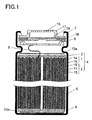
- FIG. 1 is a cross-sectional view illustrating a battery included in a battery module of a first embodiment of the present invention.
- the battery in a cylindrical shape includes an electrode group 4 in which a positive electrode 1 provided with a positive electrode lead 8 made of, for example, aluminum, and a negative electrode 2 one end of which is provided with a negative electrode lead 9 made of, for example, copper are wound with a separator 3 interposed therebetween.
- insulating plates 10a, 10b are installed above and below the electrode group 4, and the electrode group 4 with the insulating plates 10a, 10b is inserted in a battery case 5.
- the other end of the positive electrode lead 8 is welded to a sealing plate 6, and the other end of the negative electrode lead 9 is welded to a bottom of the battery case 5.
- a nonaqueous electrolyte (not shown) capable of conducting lithium ions is injected in the battery case 5.
- An opening portion of the battery case 5 is sealed by being crimped to a positive electrode cap 16, a current cutoff member 18 such as a PTC element, and the sealing plate 6 with a gasket 7 interposed between the opening portion and the members 16, 18, and 6.
- the positive electrode cap 16 is provided with a vent 17 to release gas resulted from opening of a vent mechanism 19 such as a safety valve due to a problem in the electrode group 4.
- the positive electrode 1 includes a positive electrode current collector 1a and a positive electrode layer 1b containing a positive electrode active material.
- the positive electrode layer 1b contains, as the positive electrode active material, for example, a lithium-containing compound oxide such as LiCoO 2 , LiNiO 2 , Li 2 MnO 4 , a mixture of these materials, or a complex compound of these materials.
- the positive electrode layer 1 b further contains a conductive agent and a binder.
- the conductive agent include graphites such as natural graphite and artificial graphite, and carbon blacks such as acetylene black, ketjen black, channel black, furnace black, lamp black, and thermal black.
- the binder include PVDF, polytetrafluoroethylene, polyethylene, polypropylene, an aramid resin, polyamide, polyimide, etc.
- the positive electrode current collector 1 a used for the positive electrode aluminum (Al), carbon (C), or a conductive resin can be used.
- nonaqueous electrolyte an electrolyte solution obtained by dissolving a solute in an organic solvent, or a so-called polymer electrolyte layer including the electrolyte solution solidified by macromolecules can be used.
- solute of the nonaqueous electrolyte LiPF 6 , LiBF 4 , LiClO 4 , LiAlCl 4 , LiSbF 6 , LiSCN, LiCF 3 SO 3 , LiN(CF 3 CO 2 ), LiN(CF 3 SO 2 ) 2 , or the like can be used.
- organic solvent for example, ethylene carbonate (EC), propylene carbonate, butylene carbonate, vinylene carbonate, dimethyl carbonate (DMC), diethyl carbonate, ethyl methyl carbonate (EMC), or the like can be used.
- EC ethylene carbonate
- DMC dimethyl carbonate
- EMC ethyl methyl carbonate
- a negative electrode current collector 11 of the negative electrode 2 can be metal foil made of stainless steel, nickel, copper, titanium, or the like, or thin film made of carbon or a conductive resin.
- negative electrode layers 15 of the negative electrode 2 a negative electrode active material, e.g., silicon (Si), tin (Sn), or a carbon material such as graphite, which is capable of reversibly inserting and extracting lithium ions, and has a theoretical capacity density of 833 mAh/cm 3 or higher can be used.
- a negative electrode active material e.g., silicon (Si), tin (Sn), or a carbon material such as graphite, which is capable of reversibly inserting and extracting lithium ions, and has a theoretical capacity density of 833 mAh/cm 3 or higher can be used.
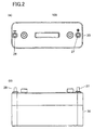
- a battery module of the first embodiment of the present invention will be described below with reference to FIGS 2A, 2B , and 3 .
- FIG. 2A is a top view illustrating the exterior of a battery module 100 of the first embodiment of the present invention.
- FIG. 2B is a side view illustrating the exterior of the battery module 100 of the first embodiment of the present invention.
- FIG. 3 is an exploded perspective view illustrating the battery module of the first embodiment of the present invention.
- the battery module 100 includes a housing 30 made of, for example, an insulating resin material such as a polycarbonate resin, and a lid body 20 fitting into the housing 30.
- the housing 30 has an opening end on one face (an upper face in FIG. 3 ).
- the lid body 20 is provided to cover the opening end of the housing 30.
- a partition wall 31 is provided in space created by the housing 30 and the lid body 20, .
- the partition wall 31 is preferably made of metal or a highly heat-conductive member as an alternative to the metal in order to improve heat conduction for heat equalization.
- the battery module 100 includes a positive electrode connection member 25 and a negative electrode connection member 26 which are battery connection members configured to connect the plurality of batteries 29 in parallel.
- the positive electrode connection member 25 and the negative electrode connection member 26 are made of a metal plate such as plating of Ni, Fe-Ni, or the like.
- the positive electrode connection member 25 is arranged to cover positive electrode faces (upper faces in FIG. 3 ) of the batteries 29 placed in the housing 30.
- the negative electrode connection member 26 is arranged to cover negative electrode faces (lower faces in FIG. 3 ) of the batteries 29. That is, the batteries 29 are individually arranged in the space fully enclosed by the partition wall 31, the positive electrode connection member 25, and the negative electrode connection member 26.
- a positive electrode terminal 27 is connected to the positive electrode connection member 25.
- a negative electrode terminal 28 is connected to the negative electrode connection member 26.
- the positive electrode terminal 27 and the negative electrode terminal 28 are exposed from holes 21 formed in an upper face of the lid body 20.
- FIG. 4 is a vertical cross-sectional view along the plane A-A' of FIG. 3 .
- FIG. 5 is a perspective cross-sectional view illustrating main part of a connection portion of the battery module 100.
- the batteries 29 are arranged in the space surrounded by the partition wall 31, the positive electrode connection member 25, and the negative electrode connection member 26.
- the positive electrode connection member 25 is made of a flat metal plate, and includes a main conductive path portion 25a and a connection terminal 25b.
- the connection terminal 25b includes a plurality of connection terminals 25b so that the batteries 29 are individually connected to the positive electrode connection member 25.
- the connection terminals 25b protrude from the main conductive path portion 25a into the space.
- Each of the connection terminals 25b includes a fuse portion 25c.
- the fuse portion 25c is formed in such a manner that the cross-sectional area of a portion of the connection terminal 25b is smaller than that of the other portions of the fuse portion 25b.
- the connection terminal 25b has a uniform thickness
- the width of the fuse portion 25c of the connection terminal 25b is smaller than that of the other portions of the connection terminal 25b.
- a temperature rise ⁇ T caused by Joule heat (E) after time t from a start of flowing of a current (I) in the fuse portion 25c is given by the following expression (1), where A is the cross-sectional area of the fuse portion 25c, and L is the length of the fuse portion 25c.
- Cp specific heat capacity
- M mass
- R resistance
- p density
- L length
- r electrical resistivity
- a current flowing in the battery is about 70 A, where the internal resistance of the battery is 50 m ⁇ .
- the current flowing in the battery having the internal short-circuit increases to several times the above value because short-circuit currents from neighboring batteries also flow in the battery.
- the temperature rise caused by Joule heat is about 400°C or less, which is less than or equal to 1/4 of the above value, according to expression (1).
- FIG. 6 is a vertical cross-sectional view along the plane A-A' of FIG. 3 , and shows the case where a problem occurs in a battery. Moreover, arrows in FIG. 6 represent a current flow.
- a current equal to or higher than a predetermined value flows from the main conductive path portion 25a through the connection terminal 25b toward Battery A having a problem such as an internal short-circuit as described above.
- the present embodiment is configured such that the fuse portion 25c provided at the connection terminal 25b is blown.
- the fuse portions 25c are formed at portions of the connection terminals 25b exposed in space between the positive electrode connection member 25 and the positive electrodes 29a of the batteries 29 so that the resistance of the fuse portions 25c is higher than that of the other portions of the connection terminals 25b.
- each fuse portion 25c is formed in such a manner that the width of a portion of the connection terminal 25b is smaller than that of the other portions of the connection terminal 25b. For this reason, when a current equal to or higher than a predetermined value flows in the fuse portion 25c, high heat is generated, so that the fuse portion 25c is blown. In this way, the connection between the positive electrode connection member 25 and Battery A having a problem is broken.
- connection terminals 25b are provided in the space between the positive electrode connection member 25 and the positive electrodes 29a of the batteries 29, it is possible to easily address design variations when the connection terminals 25b are provided with the fuse portions 25c. Further, the fuse portion 25c has high heat when being blown, but the influence of the heat over the other batteries, the positive electrode connection member 25, and the like can be limited to a lower degree because the fuse portion 25c is exposed in the space.
- the fuse portions 25c are formed as a part of the connection terminals 25b, it is possible to downsize the fuse portions 25c, and the cost of materials can be reduced. Thus, the battery module itself can be downsized.
- each fuse portion 25c in the present embodiment is formed in such a manner that the width of a portion of the connection terminal 25b is smaller than that of the other portions of the connection terminal 25b, but alternatively, for example, each fuse portion 25c may be formed in such a manner that the thickness of a portion of the connection terminal 25b is smaller than that of the other potions of the connection terminal 25b.
- each fuse portion 25c may be formed in such a manner that the resistance of a material of a portion of the connection terminal 25b is higher than that of a material of the other portions of the connection terminal 25b.
- the connection terminals 25b themselves may form the fuse portions 25c.
- the fuse portions 25c may be chip fuses which can be mounted on a substrate.
- the positive electrode connection member 25 is made of a metal plate such as plating of Ni, or Fe-Ni, but may be made of plating of other materials such as Cu or Al.
- the positive electrode connection member 25 may be configured by forming interconnects made of such a metal on a substrate to provide the main conductive path portion 25a and the connection terminals 25b.
- the positive electrode connection member 25 may be configured by, for example, using chip fuses which can be mounted on a substrate as the fuse portions 25c, and mounting the chip fuses on the substrate.
- FIGS. 7 and 8 are views illustrating a configuration of a battery module 200 of another embodiment of the present invention, where FIG. 7 is a cross-sectional view, and FIG. 8 is a plan view without a lid body.
- the positive electrode connection member 25 includes a main conductive path portion 25a having a plurality of through holes 40, and a plurality of connection terminals 25b each configured to connect the main conductive path portion 25a to a positive electrode 29a of each battery 29.
- the main conductive path portion 25a is arranged in contact with a shoulder portion of each battery 29.
- the positive electrodes 29a of the batteries 29 are inserted in the through holes 40, respectively, provided in the main conductive path portion 25a.
- the battery module 200 is partitioned by the main conductive path portion 25a to have the housing 30 in which the batteries 29 are placed, and space 50 created between the main conductive path portion 25a and a lid body 20. Moreover, the housing 30 in which the batteries 29 are placed is sealed by the main conductive path portion 25a.
- connection terminal 25b One end of each connection terminal 25b is connected to the positive electrode 29a of each battery 29.
- the other end of each connection terminal 25b passes through the through hole 40, and extends in the space 50 created above the main conductive path portion 25a, thereby being connected to a surface of the main conductive path portion 25a.
- connection terminal 25b when an internal short-circuit occurs in a battery 29, the connection terminal 25b connected to the battery 29 is blown by Joule heat. That is, in the present embodiment, the connection terminals 25b themselves also serve as fuse portions 25c.
- materials for the connection terminals 25b are not particularly limited, but can be, for example, a metal thin wire or metal ribbon made of Ni or Al.
- a temperature rise caused by Joule heat at the fuse portion 25c after 1 second is about 1600°C, so that the fuse portion 25c is blown because the melting point of Ni is 1455°C.
- connection to the positive electrodes 29a and to the main conductive path portion 25a can be achieved by wire bonding, laser welding, or the like.
- the temperature rise at the connection terminal 25b connected to the battery 29 having an internal short-circuit can be accelerate by the high-temperature gas released through the vent 17 in addition to Joule heat due to a short-circuit current.
- the temperature of the high-temperature gas is usually 1000°C or higher.
- the high-temperature gas released through the vent 17 of the battery 29 having an internal short-circuit is released through the through hole 40 to the space 50 above the main conductive path portion 25a. Therefore, normally operating, neighboring batteries 29 can be prevented from being subjected to the high-temperature gas.
- the partition wall 31 is provided so that the housing 30 are partitioned for the plurality of batteries 29, but the battery connection member and the battery module of the present invention can provide advantages without the partition wall 31.
- the housing 30 may be but not limited to a configuration in which an opening end is provided on only one face of the housing 30.
- the housing 30 may have opening ends on both faces thereof.
- the present invention is applicable to battery modules and battery connection members in the battery modules such as vehicles, bicycles, and electronic tools which require high reliability and safety.
Landscapes
- Chemical & Material Sciences (AREA)
- Chemical Kinetics & Catalysis (AREA)
- Electrochemistry (AREA)
- General Chemical & Material Sciences (AREA)
- Engineering & Computer Science (AREA)
- Materials Engineering (AREA)
- Manufacturing & Machinery (AREA)
- Connection Of Batteries Or Terminals (AREA)
- Battery Mounting, Suspending (AREA)
Claims (1)
- Module de batteries incluant une pluralité de batteries (29) disposées dans un boîtier (30), dans lequel
la pluralité de batteries (29) sont connectées en parallèle par un élément de connexion de batteries (25),
l'élément de connexion de batteries (25) comporte une partie de chemin conducteur principal (25a) et une pluralité de bornes de connexion (25b), chacune étant configurée pour connecter la partie de chemin conducteur principal (25a) à l'une des électrodes (29a) de chaque batterie (29),
caractérisée en ce que
la partie de chemin conducteur principal (25a) comporte une pluralité de trous traversants (40) dans chacun desquels est insérée l'électrode (29a) de chaque batterie (29), et la partie de chemin conducteur principal (25a) est agencée en contact avec une partie d'épaulement de chaque batterie (29),
le module de batteries est partagé par la partie de chemin conducteur principal (25a) afin que le boîtier (30) et l'espace (50) soient créés entre la partie de chemin conducteur principal (25a) et un corps de couvercle (20), où les gaz libérés par un évent (17) fournis à chaque batterie (29) sont libérés de l'espace (50) par l'intermédiaire du trou traversant (40), une extrémité de chaque borne de connexion (25b) est connectée à l'électrode (29a) de chaque batterie (29) et l'autre extrémité de chaque borne de connexion (25b) traverse le trou traversant (40) et se prolonge dans l'espace (50) et est connectée à la partie de chemin conducteur principal (25a), et
les bornes de connexion (25b) servent également de parties de fusible qui fondent lorsqu'un courant d'une valeur prédéterminée circule à travers celles-ci.
Applications Claiming Priority (2)
| Application Number | Priority Date | Filing Date | Title |
|---|---|---|---|
| JP2009168518 | 2009-07-17 | ||
| PCT/JP2010/004488 WO2011007535A1 (fr) | 2009-07-17 | 2010-07-09 | Élément de connexion de piles et module de piles l'utilisant |
Publications (3)
| Publication Number | Publication Date |
|---|---|
| EP2339669A1 EP2339669A1 (fr) | 2011-06-29 |
| EP2339669A4 EP2339669A4 (fr) | 2012-02-29 |
| EP2339669B1 true EP2339669B1 (fr) | 2013-03-13 |
Family
ID=43449146
Family Applications (1)
| Application Number | Title | Priority Date | Filing Date |
|---|---|---|---|
| EP10799599A Active EP2339669B1 (fr) | 2009-07-17 | 2010-07-09 | Élément de connexion de piles et module de piles l'utilisant |
Country Status (6)
| Country | Link |
|---|---|
| US (1) | US9184426B2 (fr) |
| EP (1) | EP2339669B1 (fr) |
| JP (1) | JP4815016B2 (fr) |
| KR (1) | KR20120052189A (fr) |
| CN (1) | CN102272980B (fr) |
| WO (1) | WO2011007535A1 (fr) |
Cited By (1)
| Publication number | Priority date | Publication date | Assignee | Title |
|---|---|---|---|---|
| TWI495179B (zh) * | 2014-06-17 | 2015-08-01 | Energy Control Ltd | 以二導電條將複數二次電池並聯而構成集合電池的結構 |
Families Citing this family (38)
| Publication number | Priority date | Publication date | Assignee | Title |
|---|---|---|---|---|
| KR101072955B1 (ko) * | 2009-08-14 | 2011-10-12 | 에스비리모티브 주식회사 | 전지 모듈 |
| WO2012053610A1 (fr) * | 2010-10-21 | 2012-04-26 | 株式会社キャプテックス | Connecteur de piles, module de bloc-batterie, procédé de fabrication de module de bloc-batterie et de connecteur de piles |
| JP2012234698A (ja) * | 2011-04-28 | 2012-11-29 | Toyota Motor Corp | 蓄電装置 |
| WO2012164884A1 (fr) | 2011-05-31 | 2012-12-06 | パナソニック株式会社 | Tableau de fusibles et bloc-batterie équipé de celui-ci |
| EP2555280B1 (fr) * | 2011-08-05 | 2016-11-02 | Optimum Battery Co., Ltd. | Plaque d'électrodes améliorée ayant un dispositif de sécurité et système de batterie de puissance l'utilisant |
| CN103022578B (zh) * | 2011-09-22 | 2016-05-18 | 深圳市沃特玛电池有限公司 | 一种动力电池组的安全结构 |
| CN103797618B (zh) * | 2011-09-16 | 2017-05-03 | 株式会社Lg 化学 | 用于二次电池的部件及其制造方法和使用该部件制造的二次电池及多电池设备 |
| US9203117B2 (en) * | 2012-05-04 | 2015-12-01 | Samsung Sdi Co., Ltd. | Rechargeable secondary battery |
| KR101367197B1 (ko) * | 2012-07-30 | 2014-02-25 | 에너지 컨트롤 리미티드 | 이차 전지 팩 |
| JP5672294B2 (ja) * | 2012-11-30 | 2015-02-18 | トヨタ自動車株式会社 | 組電池及び車両 |
| JP6018937B2 (ja) * | 2013-01-29 | 2016-11-02 | 三洋電機株式会社 | 電極部材、および、電池ブロック |
| US20140212695A1 (en) * | 2013-01-30 | 2014-07-31 | Tesla Motors, Inc. | Flexible printed circuit as high voltage interconnect in battery modules |
| JP6006134B2 (ja) * | 2013-02-08 | 2016-10-12 | トヨタ自動車株式会社 | 接続部材 |
| US10396326B2 (en) * | 2013-02-14 | 2019-08-27 | Sanyo Electric Co., Ltd. | Battery block |
| JP6109926B2 (ja) * | 2013-03-29 | 2017-04-05 | 三洋電機株式会社 | 電池パック |
| CN104241730B (zh) * | 2013-06-13 | 2018-03-20 | 南京德朔实业有限公司 | 具有散热系统的电池包 |
| KR101696010B1 (ko) | 2013-06-19 | 2017-01-12 | 삼성에스디아이 주식회사 | 이차 전지 |
| KR102073193B1 (ko) * | 2013-09-23 | 2020-02-04 | 삼성에스디아이 주식회사 | 배터리 팩 |
| US10103365B2 (en) * | 2013-12-31 | 2018-10-16 | Chervon (Hk) Limited | Battery pack |
| JP6216254B2 (ja) * | 2014-01-28 | 2017-10-18 | ダイキョーニシカワ株式会社 | 電池モジュール |
| KR102172843B1 (ko) * | 2014-03-20 | 2020-11-02 | 삼성에스디아이 주식회사 | 이차 전지 |
| KR102248595B1 (ko) | 2014-04-15 | 2021-05-06 | 삼성에스디아이 주식회사 | 이차 전지 |
| US10211443B2 (en) * | 2014-09-10 | 2019-02-19 | Cellink Corporation | Battery interconnects |
| CN106663773B (zh) * | 2014-11-04 | 2020-05-05 | 松下知识产权经营株式会社 | 电极构件及集电板、电池组 |
| US9741997B2 (en) | 2014-11-05 | 2017-08-22 | Samsung Sdi Co., Ltd. | Rechargeable battery |
| JP2018521446A (ja) * | 2015-05-11 | 2018-08-02 | ゴゴロ インク | 可搬型多セル電気エネルギー貯蔵装置用電気コネクタ |
| DE102016116581A1 (de) * | 2016-06-03 | 2018-03-01 | E-Seven Systems Technology Management Ltd | Verbindungsplatte für eine Batterie und Batterie |
| EP3282501B1 (fr) | 2016-08-08 | 2020-05-13 | Voltlabor GmbH | Batterie, element de batterie pour la batterie et barrette de connexion associee |
| EP3316352B1 (fr) * | 2016-10-27 | 2021-03-24 | Robert Bosch GmbH | Procédé de test de sécurité pour déterminer des états cellulaires critiques par provocation de court-circuit interne |
| US20180138478A1 (en) * | 2016-11-14 | 2018-05-17 | Anhui Xinen Technology Co., Ltd. | Alleviating explosion propagation in a battery module |
| KR102350459B1 (ko) | 2017-12-07 | 2022-01-11 | 주식회사 엘지에너지솔루션 | 원통형 이차전지 모듈 |
| JP7105081B2 (ja) | 2018-03-29 | 2022-07-22 | 三洋電機株式会社 | 組電池、及び、これに用いられる二次電池 |
| US11824226B2 (en) | 2018-09-26 | 2023-11-21 | Panasonic Intellectual Property Management Co., Ltd. | Battery module |
| KR102487835B1 (ko) * | 2019-01-16 | 2023-01-12 | 주식회사 엘지에너지솔루션 | 충전 시간을 단축시킨 이차전지의 충전 방법 |
| CN113748558A (zh) | 2019-03-14 | 2021-12-03 | 杰耐瑞克动力系统公司 | 电池组模块的热管理 |
| CN111186302A (zh) * | 2020-01-14 | 2020-05-22 | 中车资阳机车有限公司 | 一种纯电动轨道机车动力电池安全保障方法 |
| JP2024512188A (ja) | 2021-03-24 | 2024-03-19 | セルリンク コーポレーション | 多層フレキシブルバッテリー相互接続及びその製造方法 |
| DE112022003072T5 (de) * | 2021-07-20 | 2024-04-04 | Milwaukee Electric Tool Corporation | Batteriesatz |
Family Cites Families (22)
| Publication number | Priority date | Publication date | Assignee | Title |
|---|---|---|---|---|
| JPH0777006B2 (ja) | 1987-08-21 | 1995-08-16 | ティアツク株式会社 | 磁気再生装置 |
| US5401595A (en) | 1991-12-06 | 1995-03-28 | Yuasa Corporation | Film type battery and layer-built film type battery |
| JP2604103B2 (ja) * | 1993-02-05 | 1997-04-30 | 日本碍子株式会社 | 単電池の並列接続ブス及び接続構造 |
| US5419983A (en) * | 1993-07-20 | 1995-05-30 | Matsushita Electric Industrial Co., Ltd. | Lead acid battery |
| JP3658877B2 (ja) * | 1996-08-01 | 2005-06-08 | 松下電器産業株式会社 | バッテリーパック |
| EP0892450B1 (fr) * | 1997-03-24 | 2004-05-12 | Matsushita Electric Industrial Co., Ltd. | Batterie d'alimentation électrique |
| JP3774977B2 (ja) * | 1997-03-24 | 2006-05-17 | トヨタ自動車株式会社 | 電池電源装置とこれに用いるエンドプレート |
| JP3540649B2 (ja) * | 1999-01-28 | 2004-07-07 | 三洋電機株式会社 | 電源装置 |
| DE10002142B4 (de) * | 1999-01-28 | 2004-04-29 | Sanyo Electric Co., Ltd., Moriguchi | Stromversorgung enthaltend wiederaufladbare Batterien |
| JP3691273B2 (ja) * | 1999-01-29 | 2005-09-07 | 三洋電機株式会社 | 電源装置 |
| WO2001069699A1 (fr) * | 2000-03-14 | 2001-09-20 | Matsushita Electric Industrial Co., Ltd. | Cellule secondaire et procede de fixation des fils correspondant, et alimentation electrique du type batterie |
| JP3501734B2 (ja) | 2000-07-05 | 2004-03-02 | 三洋ジ−エスソフトエナジー株式会社 | 電池パック |
| EP1313193A1 (fr) * | 2001-11-19 | 2003-05-21 | Dialog Semiconductor GmbH | Système de protection de batterie avec fusible à claquage séquentiel |
| KR100551396B1 (ko) * | 2003-10-15 | 2006-02-09 | 삼성에스디아이 주식회사 | 일체형 캡조립체를 갖는 이차전지 및 일체형 캡조립체형성 방법 |
| KR100876456B1 (ko) * | 2004-12-24 | 2008-12-29 | 주식회사 엘지화학 | 분리형 커넥팅 부재 및 그것을 이용한 이차전지 모듈의제조방법 |
| CA2592245C (fr) * | 2004-12-24 | 2010-03-30 | Lg Chem, Ltd. | Element de connexion separable pour module de batterie secondaire et procede d'amelioration des performances du module de batterie par nivellement de la tension |
| CN101017887B (zh) * | 2005-11-28 | 2010-06-16 | Nec东金株式会社 | 电池层叠体及电池组件 |
| JP5010250B2 (ja) * | 2005-11-28 | 2012-08-29 | Necエナジーデバイス株式会社 | 電池積層体および電池パック |
| US7671565B2 (en) | 2006-02-13 | 2010-03-02 | Tesla Motors, Inc. | Battery pack and method for protecting batteries |
| CN2935488Y (zh) | 2006-08-15 | 2007-08-15 | 深圳市格瑞普电池有限公司 | 具有短路保护功能的电池组 |
| US7923144B2 (en) * | 2007-03-31 | 2011-04-12 | Tesla Motors, Inc. | Tunable frangible battery pack system |
| JP2009231138A (ja) * | 2008-03-24 | 2009-10-08 | Toshiba Corp | 電池パック |
-
2010
- 2010-07-09 KR KR1020117005812A patent/KR20120052189A/ko not_active Application Discontinuation
- 2010-07-09 JP JP2010550964A patent/JP4815016B2/ja active Active
- 2010-07-09 CN CN201080004184.9A patent/CN102272980B/zh active Active
- 2010-07-09 EP EP10799599A patent/EP2339669B1/fr active Active
- 2010-07-09 WO PCT/JP2010/004488 patent/WO2011007535A1/fr active Application Filing
- 2010-07-09 US US13/119,640 patent/US9184426B2/en active Active
Cited By (1)
| Publication number | Priority date | Publication date | Assignee | Title |
|---|---|---|---|---|
| TWI495179B (zh) * | 2014-06-17 | 2015-08-01 | Energy Control Ltd | 以二導電條將複數二次電池並聯而構成集合電池的結構 |
Also Published As
| Publication number | Publication date |
|---|---|
| JPWO2011007535A1 (ja) | 2012-12-20 |
| US9184426B2 (en) | 2015-11-10 |
| EP2339669A4 (fr) | 2012-02-29 |
| CN102272980A (zh) | 2011-12-07 |
| CN102272980B (zh) | 2014-08-27 |
| WO2011007535A1 (fr) | 2011-01-20 |
| US20110177365A1 (en) | 2011-07-21 |
| EP2339669A1 (fr) | 2011-06-29 |
| KR20120052189A (ko) | 2012-05-23 |
| JP4815016B2 (ja) | 2011-11-16 |
Similar Documents
| Publication | Publication Date | Title |
|---|---|---|
| EP2339669B1 (fr) | Élément de connexion de piles et module de piles l'utilisant | |
| US8399112B2 (en) | Battery module and battery pack using the same | |
| US8062785B2 (en) | Battery module and battery pack using the same | |
| US8475952B2 (en) | Battery module and battery pack using the same | |
| EP2416401B1 (fr) | Dispositif électromécanique comprenant une tige d'électrode dotée d'un dispositif de protection | |
| EP2515363B1 (fr) | Batterie secondaire | |
| KR100659856B1 (ko) | 파우치형 리튬 이차 전지 | |
| KR101160400B1 (ko) | 전지 모듈 및 그들을 이용한 전지 팩 | |
| JP4973824B2 (ja) | 電池モジュール | |
| US20130157115A1 (en) | Assembled battery | |
| US20110151297A1 (en) | Battery and battery pack | |
| KR101999529B1 (ko) | 노치가 형성된 리드박스를 포함하는 파우치형 이차전지 | |
| US9065152B2 (en) | Secondary battery with an improved safety | |
| KR100624977B1 (ko) | 파우치형 리튬 이차 전지 | |
| KR100614401B1 (ko) | 이차 전지 | |
| KR102294996B1 (ko) | 전도성 튜브를 이용한 전극리드를 포함하는 이차전지 |
Legal Events
| Date | Code | Title | Description |
|---|---|---|---|
| PUAI | Public reference made under article 153(3) epc to a published international application that has entered the european phase |
Free format text: ORIGINAL CODE: 0009012 |
|
| 17P | Request for examination filed |
Effective date: 20110216 |
|
| AK | Designated contracting states |
Kind code of ref document: A1 Designated state(s): AL AT BE BG CH CY CZ DE DK EE ES FI FR GB GR HR HU IE IS IT LI LT LU LV MC MK MT NL NO PL PT RO SE SI SK SM TR |
|
| AX | Request for extension of the european patent |
Extension state: BA ME RS |
|
| A4 | Supplementary search report drawn up and despatched |
Effective date: 20120201 |
|
| RIC1 | Information provided on ipc code assigned before grant |
Ipc: H01M 6/50 20060101ALI20120126BHEP Ipc: H01M 2/34 20060101ALI20120126BHEP Ipc: H01M 2/10 20060101ALI20120126BHEP Ipc: H01M 2/20 20060101AFI20120126BHEP |
|
| GRAP | Despatch of communication of intention to grant a patent |
Free format text: ORIGINAL CODE: EPIDOSNIGR1 |
|
| RIN1 | Information on inventor provided before grant (corrected) |
Inventor name: ITOI, TOSHIKI C/O PANASONIC CORPORATION, Inventor name: TAKASAKI, HIROSHI C/O PANASONIC CORPORATION, Inventor name: YASUI, SHUNSUKE C/O PANASONIC CORPORATION, |
|
| DAX | Request for extension of the european patent (deleted) | ||
| GRAS | Grant fee paid |
Free format text: ORIGINAL CODE: EPIDOSNIGR3 |
|
| GRAA | (expected) grant |
Free format text: ORIGINAL CODE: 0009210 |
|
| AK | Designated contracting states |
Kind code of ref document: B1 Designated state(s): AL AT BE BG CH CY CZ DE DK EE ES FI FR GB GR HR HU IE IS IT LI LT LU LV MC MK MT NL NO PL PT RO SE SI SK SM TR |
|
| REG | Reference to a national code |
Ref country code: GB Ref legal event code: FG4D |
|
| REG | Reference to a national code |
Ref country code: AT Ref legal event code: REF Ref document number: 601266 Country of ref document: AT Kind code of ref document: T Effective date: 20130315 Ref country code: CH Ref legal event code: EP |
|
| REG | Reference to a national code |
Ref country code: IE Ref legal event code: FG4D |
|
| REG | Reference to a national code |
Ref country code: DE Ref legal event code: R096 Ref document number: 602010005504 Country of ref document: DE Effective date: 20130508 |
|
| PG25 | Lapsed in a contracting state [announced via postgrant information from national office to epo] |
Ref country code: SE Free format text: LAPSE BECAUSE OF FAILURE TO SUBMIT A TRANSLATION OF THE DESCRIPTION OR TO PAY THE FEE WITHIN THE PRESCRIBED TIME-LIMIT Effective date: 20130313 Ref country code: LT Free format text: LAPSE BECAUSE OF FAILURE TO SUBMIT A TRANSLATION OF THE DESCRIPTION OR TO PAY THE FEE WITHIN THE PRESCRIBED TIME-LIMIT Effective date: 20130313 Ref country code: NO Free format text: LAPSE BECAUSE OF FAILURE TO SUBMIT A TRANSLATION OF THE DESCRIPTION OR TO PAY THE FEE WITHIN THE PRESCRIBED TIME-LIMIT Effective date: 20130613 Ref country code: BG Free format text: LAPSE BECAUSE OF FAILURE TO SUBMIT A TRANSLATION OF THE DESCRIPTION OR TO PAY THE FEE WITHIN THE PRESCRIBED TIME-LIMIT Effective date: 20130613 Ref country code: ES Free format text: LAPSE BECAUSE OF FAILURE TO SUBMIT A TRANSLATION OF THE DESCRIPTION OR TO PAY THE FEE WITHIN THE PRESCRIBED TIME-LIMIT Effective date: 20130624 |
|
| REG | Reference to a national code |
Ref country code: AT Ref legal event code: MK05 Ref document number: 601266 Country of ref document: AT Kind code of ref document: T Effective date: 20130313 |
|
| REG | Reference to a national code |
Ref country code: NL Ref legal event code: VDEP Effective date: 20130313 |
|
| REG | Reference to a national code |
Ref country code: LT Ref legal event code: MG4D |
|
| PG25 | Lapsed in a contracting state [announced via postgrant information from national office to epo] |
Ref country code: GR Free format text: LAPSE BECAUSE OF FAILURE TO SUBMIT A TRANSLATION OF THE DESCRIPTION OR TO PAY THE FEE WITHIN THE PRESCRIBED TIME-LIMIT Effective date: 20130614 Ref country code: LV Free format text: LAPSE BECAUSE OF FAILURE TO SUBMIT A TRANSLATION OF THE DESCRIPTION OR TO PAY THE FEE WITHIN THE PRESCRIBED TIME-LIMIT Effective date: 20130313 Ref country code: SI Free format text: LAPSE BECAUSE OF FAILURE TO SUBMIT A TRANSLATION OF THE DESCRIPTION OR TO PAY THE FEE WITHIN THE PRESCRIBED TIME-LIMIT Effective date: 20130313 Ref country code: FI Free format text: LAPSE BECAUSE OF FAILURE TO SUBMIT A TRANSLATION OF THE DESCRIPTION OR TO PAY THE FEE WITHIN THE PRESCRIBED TIME-LIMIT Effective date: 20130313 |
|
| PG25 | Lapsed in a contracting state [announced via postgrant information from national office to epo] |
Ref country code: HR Free format text: LAPSE BECAUSE OF FAILURE TO SUBMIT A TRANSLATION OF THE DESCRIPTION OR TO PAY THE FEE WITHIN THE PRESCRIBED TIME-LIMIT Effective date: 20130313 Ref country code: BE Free format text: LAPSE BECAUSE OF FAILURE TO SUBMIT A TRANSLATION OF THE DESCRIPTION OR TO PAY THE FEE WITHIN THE PRESCRIBED TIME-LIMIT Effective date: 20130313 |
|
| PG25 | Lapsed in a contracting state [announced via postgrant information from national office to epo] |
Ref country code: NL Free format text: LAPSE BECAUSE OF FAILURE TO SUBMIT A TRANSLATION OF THE DESCRIPTION OR TO PAY THE FEE WITHIN THE PRESCRIBED TIME-LIMIT Effective date: 20130313 Ref country code: IS Free format text: LAPSE BECAUSE OF FAILURE TO SUBMIT A TRANSLATION OF THE DESCRIPTION OR TO PAY THE FEE WITHIN THE PRESCRIBED TIME-LIMIT Effective date: 20130713 Ref country code: PT Free format text: LAPSE BECAUSE OF FAILURE TO SUBMIT A TRANSLATION OF THE DESCRIPTION OR TO PAY THE FEE WITHIN THE PRESCRIBED TIME-LIMIT Effective date: 20130715 Ref country code: RO Free format text: LAPSE BECAUSE OF FAILURE TO SUBMIT A TRANSLATION OF THE DESCRIPTION OR TO PAY THE FEE WITHIN THE PRESCRIBED TIME-LIMIT Effective date: 20130313 Ref country code: AT Free format text: LAPSE BECAUSE OF FAILURE TO SUBMIT A TRANSLATION OF THE DESCRIPTION OR TO PAY THE FEE WITHIN THE PRESCRIBED TIME-LIMIT Effective date: 20130313 Ref country code: SK Free format text: LAPSE BECAUSE OF FAILURE TO SUBMIT A TRANSLATION OF THE DESCRIPTION OR TO PAY THE FEE WITHIN THE PRESCRIBED TIME-LIMIT Effective date: 20130313 Ref country code: EE Free format text: LAPSE BECAUSE OF FAILURE TO SUBMIT A TRANSLATION OF THE DESCRIPTION OR TO PAY THE FEE WITHIN THE PRESCRIBED TIME-LIMIT Effective date: 20130313 Ref country code: CZ Free format text: LAPSE BECAUSE OF FAILURE TO SUBMIT A TRANSLATION OF THE DESCRIPTION OR TO PAY THE FEE WITHIN THE PRESCRIBED TIME-LIMIT Effective date: 20130313 |
|
| PG25 | Lapsed in a contracting state [announced via postgrant information from national office to epo] |
Ref country code: PL Free format text: LAPSE BECAUSE OF FAILURE TO SUBMIT A TRANSLATION OF THE DESCRIPTION OR TO PAY THE FEE WITHIN THE PRESCRIBED TIME-LIMIT Effective date: 20130313 |
|
| PLBE | No opposition filed within time limit |
Free format text: ORIGINAL CODE: 0009261 |
|
| STAA | Information on the status of an ep patent application or granted ep patent |
Free format text: STATUS: NO OPPOSITION FILED WITHIN TIME LIMIT |
|
| PG25 | Lapsed in a contracting state [announced via postgrant information from national office to epo] |
Ref country code: DK Free format text: LAPSE BECAUSE OF FAILURE TO SUBMIT A TRANSLATION OF THE DESCRIPTION OR TO PAY THE FEE WITHIN THE PRESCRIBED TIME-LIMIT Effective date: 20130313 |
|
| 26N | No opposition filed |
Effective date: 20131216 |
|
| PG25 | Lapsed in a contracting state [announced via postgrant information from national office to epo] |
Ref country code: IT Free format text: LAPSE BECAUSE OF FAILURE TO SUBMIT A TRANSLATION OF THE DESCRIPTION OR TO PAY THE FEE WITHIN THE PRESCRIBED TIME-LIMIT Effective date: 20130313 Ref country code: MC Free format text: LAPSE BECAUSE OF FAILURE TO SUBMIT A TRANSLATION OF THE DESCRIPTION OR TO PAY THE FEE WITHIN THE PRESCRIBED TIME-LIMIT Effective date: 20130313 |
|
| REG | Reference to a national code |
Ref country code: DE Ref legal event code: R097 Ref document number: 602010005504 Country of ref document: DE Effective date: 20131216 |
|
| REG | Reference to a national code |
Ref country code: IE Ref legal event code: MM4A |
|
| PG25 | Lapsed in a contracting state [announced via postgrant information from national office to epo] |
Ref country code: IE Free format text: LAPSE BECAUSE OF NON-PAYMENT OF DUE FEES Effective date: 20130709 |
|
| REG | Reference to a national code |
Ref country code: CH Ref legal event code: PL |
|
| GBPC | Gb: european patent ceased through non-payment of renewal fee |
Effective date: 20140709 |
|
| PG25 | Lapsed in a contracting state [announced via postgrant information from national office to epo] |
Ref country code: CH Free format text: LAPSE BECAUSE OF NON-PAYMENT OF DUE FEES Effective date: 20140731 Ref country code: LI Free format text: LAPSE BECAUSE OF NON-PAYMENT OF DUE FEES Effective date: 20140731 |
|
| PG25 | Lapsed in a contracting state [announced via postgrant information from national office to epo] |
Ref country code: GB Free format text: LAPSE BECAUSE OF NON-PAYMENT OF DUE FEES Effective date: 20140709 Ref country code: SM Free format text: LAPSE BECAUSE OF FAILURE TO SUBMIT A TRANSLATION OF THE DESCRIPTION OR TO PAY THE FEE WITHIN THE PRESCRIBED TIME-LIMIT Effective date: 20130313 |
|
| PG25 | Lapsed in a contracting state [announced via postgrant information from national office to epo] |
Ref country code: TR Free format text: LAPSE BECAUSE OF FAILURE TO SUBMIT A TRANSLATION OF THE DESCRIPTION OR TO PAY THE FEE WITHIN THE PRESCRIBED TIME-LIMIT Effective date: 20130313 Ref country code: MT Free format text: LAPSE BECAUSE OF FAILURE TO SUBMIT A TRANSLATION OF THE DESCRIPTION OR TO PAY THE FEE WITHIN THE PRESCRIBED TIME-LIMIT Effective date: 20130313 Ref country code: CY Free format text: LAPSE BECAUSE OF FAILURE TO SUBMIT A TRANSLATION OF THE DESCRIPTION OR TO PAY THE FEE WITHIN THE PRESCRIBED TIME-LIMIT Effective date: 20130313 |
|
| PG25 | Lapsed in a contracting state [announced via postgrant information from national office to epo] |
Ref country code: MK Free format text: LAPSE BECAUSE OF FAILURE TO SUBMIT A TRANSLATION OF THE DESCRIPTION OR TO PAY THE FEE WITHIN THE PRESCRIBED TIME-LIMIT Effective date: 20130313 Ref country code: HU Free format text: LAPSE BECAUSE OF FAILURE TO SUBMIT A TRANSLATION OF THE DESCRIPTION OR TO PAY THE FEE WITHIN THE PRESCRIBED TIME-LIMIT; INVALID AB INITIO Effective date: 20100709 Ref country code: LU Free format text: LAPSE BECAUSE OF NON-PAYMENT OF DUE FEES Effective date: 20130709 |
|
| REG | Reference to a national code |
Ref country code: FR Ref legal event code: PLFP Year of fee payment: 7 |
|
| REG | Reference to a national code |
Ref country code: FR Ref legal event code: PLFP Year of fee payment: 8 |
|
| REG | Reference to a national code |
Ref country code: FR Ref legal event code: PLFP Year of fee payment: 9 |
|
| PG25 | Lapsed in a contracting state [announced via postgrant information from national office to epo] |
Ref country code: AL Free format text: LAPSE BECAUSE OF FAILURE TO SUBMIT A TRANSLATION OF THE DESCRIPTION OR TO PAY THE FEE WITHIN THE PRESCRIBED TIME-LIMIT Effective date: 20130313 |
|
| REG | Reference to a national code |
Ref country code: DE Ref legal event code: R079 Ref document number: 602010005504 Country of ref document: DE Free format text: PREVIOUS MAIN CLASS: H01M0002200000 Ipc: H01M0050500000 |
|
| P01 | Opt-out of the competence of the unified patent court (upc) registered |
Effective date: 20230808 |
|
| PGFP | Annual fee paid to national office [announced via postgrant information from national office to epo] |
Ref country code: FR Payment date: 20230725 Year of fee payment: 14 Ref country code: DE Payment date: 20230719 Year of fee payment: 14 |