EP2336495A1 - Abgasturbolader - Google Patents
Abgasturbolader Download PDFInfo
- Publication number
- EP2336495A1 EP2336495A1 EP09015573A EP09015573A EP2336495A1 EP 2336495 A1 EP2336495 A1 EP 2336495A1 EP 09015573 A EP09015573 A EP 09015573A EP 09015573 A EP09015573 A EP 09015573A EP 2336495 A1 EP2336495 A1 EP 2336495A1
- Authority
- EP
- European Patent Office
- Prior art keywords
- housing
- exhaust gas
- gas turbocharger
- bearing housing
- locking
- Prior art date
- Legal status (The legal status is an assumption and is not a legal conclusion. Google has not performed a legal analysis and makes no representation as to the accuracy of the status listed.)
- Granted
Links
- 238000003801 milling Methods 0.000 claims description 2
- 230000000295 complement effect Effects 0.000 claims 1
- 238000003754 machining Methods 0.000 claims 1
- 230000001133 acceleration Effects 0.000 description 2
- 238000000034 method Methods 0.000 description 2
- 230000001419 dependent effect Effects 0.000 description 1
- 238000011161 development Methods 0.000 description 1
- 230000018109 developmental process Effects 0.000 description 1
- 238000005538 encapsulation Methods 0.000 description 1
- 238000009434 installation Methods 0.000 description 1
- 238000004519 manufacturing process Methods 0.000 description 1
- 125000006850 spacer group Chemical group 0.000 description 1
Images


Classifications
-
- F—MECHANICAL ENGINEERING; LIGHTING; HEATING; WEAPONS; BLASTING
- F02—COMBUSTION ENGINES; HOT-GAS OR COMBUSTION-PRODUCT ENGINE PLANTS
- F02C—GAS-TURBINE PLANTS; AIR INTAKES FOR JET-PROPULSION PLANTS; CONTROLLING FUEL SUPPLY IN AIR-BREATHING JET-PROPULSION PLANTS
- F02C6/00—Plural gas-turbine plants; Combinations of gas-turbine plants with other apparatus; Adaptations of gas-turbine plants for special use
- F02C6/04—Gas-turbine plants providing heated or pressurised working fluid for other apparatus, e.g. without mechanical power output
- F02C6/10—Gas-turbine plants providing heated or pressurised working fluid for other apparatus, e.g. without mechanical power output supplying working fluid to a user, e.g. a chemical process, which returns working fluid to a turbine of the plant
- F02C6/12—Turbochargers, i.e. plants for augmenting mechanical power output of internal-combustion piston engines by increase of charge pressure
-
- F—MECHANICAL ENGINEERING; LIGHTING; HEATING; WEAPONS; BLASTING
- F02—COMBUSTION ENGINES; HOT-GAS OR COMBUSTION-PRODUCT ENGINE PLANTS
- F02B—INTERNAL-COMBUSTION PISTON ENGINES; COMBUSTION ENGINES IN GENERAL
- F02B39/00—Component parts, details, or accessories relating to, driven charging or scavenging pumps, not provided for in groups F02B33/00 - F02B37/00
-
- F—MECHANICAL ENGINEERING; LIGHTING; HEATING; WEAPONS; BLASTING
- F01—MACHINES OR ENGINES IN GENERAL; ENGINE PLANTS IN GENERAL; STEAM ENGINES
- F01D—NON-POSITIVE DISPLACEMENT MACHINES OR ENGINES, e.g. STEAM TURBINES
- F01D25/00—Component parts, details, or accessories, not provided for in, or of interest apart from, other groups
- F01D25/16—Arrangement of bearings; Supporting or mounting bearings in casings
- F01D25/162—Bearing supports
-
- F—MECHANICAL ENGINEERING; LIGHTING; HEATING; WEAPONS; BLASTING
- F01—MACHINES OR ENGINES IN GENERAL; ENGINE PLANTS IN GENERAL; STEAM ENGINES
- F01D—NON-POSITIVE DISPLACEMENT MACHINES OR ENGINES, e.g. STEAM TURBINES
- F01D25/00—Component parts, details, or accessories, not provided for in, or of interest apart from, other groups
- F01D25/24—Casings; Casing parts, e.g. diaphragms, casing fastenings
- F01D25/243—Flange connections; Bolting arrangements
-
- F—MECHANICAL ENGINEERING; LIGHTING; HEATING; WEAPONS; BLASTING
- F01—MACHINES OR ENGINES IN GENERAL; ENGINE PLANTS IN GENERAL; STEAM ENGINES
- F01D—NON-POSITIVE DISPLACEMENT MACHINES OR ENGINES, e.g. STEAM TURBINES
- F01D25/00—Component parts, details, or accessories, not provided for in, or of interest apart from, other groups
- F01D25/24—Casings; Casing parts, e.g. diaphragms, casing fastenings
- F01D25/246—Fastening of diaphragms or stator-rings
-
- F—MECHANICAL ENGINEERING; LIGHTING; HEATING; WEAPONS; BLASTING
- F01—MACHINES OR ENGINES IN GENERAL; ENGINE PLANTS IN GENERAL; STEAM ENGINES
- F01D—NON-POSITIVE DISPLACEMENT MACHINES OR ENGINES, e.g. STEAM TURBINES
- F01D9/00—Stators
- F01D9/02—Nozzles; Nozzle boxes; Stator blades; Guide conduits, e.g. individual nozzles
- F01D9/026—Scrolls for radial machines or engines
-
- F—MECHANICAL ENGINEERING; LIGHTING; HEATING; WEAPONS; BLASTING
- F01—MACHINES OR ENGINES IN GENERAL; ENGINE PLANTS IN GENERAL; STEAM ENGINES
- F01D—NON-POSITIVE DISPLACEMENT MACHINES OR ENGINES, e.g. STEAM TURBINES
- F01D9/00—Stators
- F01D9/02—Nozzles; Nozzle boxes; Stator blades; Guide conduits, e.g. individual nozzles
- F01D9/04—Nozzles; Nozzle boxes; Stator blades; Guide conduits, e.g. individual nozzles forming ring or sector
-
- F—MECHANICAL ENGINEERING; LIGHTING; HEATING; WEAPONS; BLASTING
- F05—INDEXING SCHEMES RELATING TO ENGINES OR PUMPS IN VARIOUS SUBCLASSES OF CLASSES F01-F04
- F05D—INDEXING SCHEME FOR ASPECTS RELATING TO NON-POSITIVE-DISPLACEMENT MACHINES OR ENGINES, GAS-TURBINES OR JET-PROPULSION PLANTS
- F05D2220/00—Application
- F05D2220/40—Application in turbochargers
-
- F—MECHANICAL ENGINEERING; LIGHTING; HEATING; WEAPONS; BLASTING
- F05—INDEXING SCHEMES RELATING TO ENGINES OR PUMPS IN VARIOUS SUBCLASSES OF CLASSES F01-F04
- F05D—INDEXING SCHEME FOR ASPECTS RELATING TO NON-POSITIVE-DISPLACEMENT MACHINES OR ENGINES, GAS-TURBINES OR JET-PROPULSION PLANTS
- F05D2230/00—Manufacture
- F05D2230/60—Assembly methods
- F05D2230/64—Assembly methods using positioning or alignment devices for aligning or centring, e.g. pins
- F05D2230/642—Assembly methods using positioning or alignment devices for aligning or centring, e.g. pins using maintaining alignment while permitting differential dilatation
-
- F—MECHANICAL ENGINEERING; LIGHTING; HEATING; WEAPONS; BLASTING
- F05—INDEXING SCHEMES RELATING TO ENGINES OR PUMPS IN VARIOUS SUBCLASSES OF CLASSES F01-F04
- F05D—INDEXING SCHEME FOR ASPECTS RELATING TO NON-POSITIVE-DISPLACEMENT MACHINES OR ENGINES, GAS-TURBINES OR JET-PROPULSION PLANTS
- F05D2260/00—Function
- F05D2260/30—Retaining components in desired mutual position
- F05D2260/33—Retaining components in desired mutual position with a bayonet coupling
Definitions
- the invention relates to an exhaust gas turbocharger according to the preamble of claim 1.
- Such an exhaust gas turbocharger is for example from the EP 1 734 231 A1 known.
- the assembly of the compressor housing on the bearing housing takes place in a generic turbocharger by means of a fastening device in the form of a screw, which is a time-consuming step. Because on the one hand a plurality of internal threads should be provided and the screwing is done using suitable tools.
- the first fastening device is designed as a plug-in rotary connection device, which only requires a plug-in operation and an adjoining rotational operation for locking the two components, results in the desired acceleration and simplification of the assembly process, wherein in addition no tools are required , Furthermore, such a fastening device provides the possibility of a fully mechanical assembly of the compressor housing on the bearing housing.
- the plug-in rotary connecting device according to the invention is constructed similar to a bayonet closure and may have two locking rings with corresponding locking teeth, which are attachable to the compressor housing or bearing housing.
- closure rings can also be designed as separate parts which, after their manufacture, e.g. can be attached via a press fit or by shrinking on the bearing housing or the compressor housing.
- the compressor housing it is preferably also possible to realize a direct encapsulation of the closure ring with the compressor housing.
- the required pressure between the compressor housing and the bearing housing can be achieved via a ramp on the respective contact surface of the teeth of the two halves.
- this locking pin in order to secure the compressor housing mounted on the bearing housing, it is possible to provide a locking pin which can be pressed either by spring force or manually to prevent disengagement of the connection between the bearing housing and the compressor housing.
- this locking pin may be equipped with an indicator to indicate successful assembly.
- the indicator protrudes out of the housing in case of non-successful mounting of the locking pin, while it is withdrawn in the case of successful assembly in the housing. This type of display of the assembly is also verifiable by machine.
- Fig. 1 is a broken perspective view of a possible embodiment of an exhaust gas turbocharger 1 according to the invention shown, which has a turbine housing 2 and a compressor housing 3, which are mounted on the respective adjacent ends of a bearing housing 28.
- a first fastening device 19 for fixing the bearing housing 28 on the compressor housing 3 and a second fastening device 20 for fixing the bearing housing 28 on the turbine housing 2 are each shown schematically simplified.
- the structure of the first fastening device 19 will be described in detail with reference to the following Fig. 2 to 5 be explained.
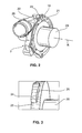
- Fig. 2 represents a perspective view of the compressor housing 3, which is fixable on the bearing housing 28 via the aforementioned first fastening means 19, wherein Fig. 2 represents the fixed state.
- the bearing housing 28 is shown in the form of a cylindrical bearing housing rubber, since the structural details of the bearing housing 28 for the explanation of the present invention are not required.
- the fastening device 19 has in the in Fig. 2 illustrated embodiment, a first locking ring 21 which is fixed to the bearing housing 3.
- the fixation can be done in the manner explained in the introduction.
- the locking ring 21 has a plurality of first locking teeth, of which a locking tooth is identified by the reference numeral 22.
- the number of latch teeth 22 may vary and is adaptable to the particular exhaust gas turbocharger type. As is clear from the Fig. 2 results, the locking teeth 22 are spaced from each other, so that there are 22 free spaces or openings 26 between the locking teeth. How further the Fig. 2 can be removed, the locking teeth 22 have inwardly on the rotational or longitudinal axis R of the exhaust gas turbocharger.
- the first connection device 19 also has a second closure ring 23, which is fixable on the bearing housing 28 in the manner explained above.
- the second locking ring 23 has a number of second locking teeth, which corresponds to that of the number of first locking teeth 22. Because in Fig. 2 the mounting state of bearing housing 28 and compressor housing 3 is shown, the second locking teeth of the second locking ring 23 in Fig. 2 not visible. However, one of these second locking teeth 24 is from the illustration of Fig. 3 seen. The distances between the second locking teeth 24 correspond to those of the first locking teeth 22, so that the locking teeth 24 can be inserted through the passage openings 26 for mounting and after this axial passing through for fixing a rotational movement takes place, due to the locking teeth 22 and 24 engage behind. Therefore, the first fastening device 19 is referred to as a plug-in rotary connection device.
- this represents a snap closure, similar to a bayonet, and can additionally with one out of the 4 and 5 apparent locking pin 27 are provided, which can be inserted into the bearing housing 28 and the compressor housing 3 and at one end has an indicator 29.
- the schematically simplified representation of the Fig. 4 This represents the open state in which the indicator 29 of the locking pin 27 is disposed outside.
- the Fig. 5 represents the secured position with recessed locking pin 27 and indicator 29.
Landscapes
- Engineering & Computer Science (AREA)
- Mechanical Engineering (AREA)
- General Engineering & Computer Science (AREA)
- Chemical & Material Sciences (AREA)
- Combustion & Propulsion (AREA)
- Chemical Kinetics & Catalysis (AREA)
- General Chemical & Material Sciences (AREA)
- Supercharger (AREA)
Abstract
Description
- Die Erfindung betrifft einen Abgasturbolader gemäß dem Oberbegriff des Anspruches 1.
- Ein derartiger Abgasturbolader ist beispielsweise aus der
EP 1 734 231 A1 bekannt. Die Montage des Verdichtergehäuses am Lagergehäuse erfolgt bei einem gattungsgemäßen Turbolader mittels einer Befestigungseinrichtung in Form einer Verschraubung, was einen zeitintensiven Arbeitsschritt darstellt. Denn zum einen ist eine Mehrzahl von Innengewinden vorzusehen und die Verschraubung erfolgt unter Verwendung geeigneter Werkzeuge. - Es ist daher Aufgabe der vorliegenden Erfindung, einen Abgasturbolader der im Oberbegriff des Anspruches 1 angegebenen Art zu schaffen, der eine Vereinfachung der Montage des Verdichtergehäuses am Lagergehäuse und eine erhebliche Beschleunigung dieser Montage ermöglicht.
- Die Lösung dieser Aufgabe erfolgt durch die Merkmale des Anspruches 1.
- Dadurch, dass die erste Befestigungseinrichtung als Steck-Dreh-Verbindungseinrichtung ausgebildet ist, die zur Montage lediglich einen Steckvorgang und einen sich daran anschließenden Drehvorgang zur Verriegelung der beiden Bauteile erfordert, ergibt sich die angestrebte Beschleunigung und Vereinfachung des Montagevorganges, wobei zudem keine Werkzeuge erforderlich sind. Ferner ergibt eine derartige Befestigungseinrichtung die Möglichkeit einer voll maschinellen Montage des Verdichtergehäuses am Lagergehäuse.
- Die Unteransprüche haben vorteilhafte Weiterbildungen der Erfindung zum Inhalt.
- Die erfindungsgemäße Steck-Dreh-Verbindungseinrichtung ist ähnlich einem Bajonettverschluss aufgebaut und kann zwei Verschlussringe mit entsprechenden Riegelzähnen aufweisen, welche am Verdichtergehäuse bzw. Lagergehäuse anbringbar sind.
- Hierbei ist es möglich, die Verschlussringe mit ihren Riegelzähnen durch eine Fräs- und Drehbearbeitung aus den Rohteilen des Lagergehäuses bzw. des Verdichtergehäuses herauszuarbeiten.
- Zum anderen können die Verschlussringe jedoch auch als separate Teile ausgebildet sein, die nach ihrer Fertigung z.B. über einen Pressverband oder durch Schrumpfen am Lagergehäuse bzw. dem Verdichtergehäuse angebracht werden können.
- Im Falle des Verdichtergehäuses ist es vorzugsweise auch möglich, einen direkten Verguss des Verschlussringes mit dem Verdichtergehäuse zu realisieren.
- Die erforderliche Pressung zwischen dem Verdichtergehäuse und dem Lagergehäuse kann über eine Auflaufschräge auf der jeweiligen Kontaktfläche der Verzahnung der beiden Hälften erreicht werden.
- Bei einer besonders bevorzugten Ausführungsform ist es zur Sicherung des am Lagergehäuse montierten Verdichtergehäuses möglich, einen Sicherungsstift vorzusehen, der entweder mittels Federkraft oder manuell eingepresst werden kann, um ein Lösen der Verbindung zwischen dem Lagergehäuse und dem Verdichtergehäuse zu verhindern. Um einen erfolgreichen Montageprozess überprüfen zu können, kann dieser Sicherungsstift mit einem Indikator ausgestattet sein, um die erfolgreiche Montage anzuzeigen. Hierbei ragt der Indikator bei nicht erfolgter Montage des Sicherungsstiftes aus dem Gehäuse heraus, während er bei erfolgter Montage in das Gehäuse zurückgezogen ist. Diese Art der Anzeige der Montage ist auch maschinell überprüfbar.
- Weitere Einzelheiten, Vorteile und Merkmale der vorliegenden Erfindung ergeben sich aus nachfolgender Beschreibung von Ausführungsbeispielen anhand der Zeichnung. Es zeigt:
- Fig. 1
- eine perspektivische, teilweise aufgebrochene Darstellung eines erfindungsgemäßen Abgasturboladers;
- Fig. 2
- eine perspektivische Darstellung des Verdichtergehäuses des Abgasturboladers gemäß
Fig. 1 , das zur Erläuterung der erfindungsgemäßen Prinzipien im am Lagergehäuse montierten Zustand dargestellt ist, wobei das Lagergehäuse als Lagergehäusedummy in stark schematisierter Darstellung sichtbar ist; - Fig. 3
- eine Teilansicht des Verschlussringes des Lagergehäuses; und
- Fig. 4 und 5
- zwei Darstellungen eines Sicherungsstiftes mit Indikator zur Anzeige einer erfolgten bzw. einer noch nicht erfolgten Montage.
- In
Fig. 1 ist in aufgebrochener perspektivischer Darstellung eine mögliche Ausführungsform eines erfindungsgemäßen Abgasturboladers 1 dargestellt, der ein Turbinengehäuse 2 und ein Verdichtergehäuse 3 aufweist, die an den jeweils benachbarten Enden eines Lagergehäuses 28 montiert sind. Hierbei ist eine erste Befestigungseinrichtung 19 zur Fixierung des Lagergehäuses 28 am Verdichtergehäuse 3 und eine zweite Befestigungseinrichtung 20 zur Fixierung des Lagergehäuses 28 am Turbinengehäuse 2 jeweils schematisch vereinfacht dargestellt. Der Aufbau der ersten Befestigungseinrichtung 19 wird im Detail anhand der nachfolgendenFig. 2 bis 5 erläutert werden. - Alle übrigen in
Fig. 1 durch die eingezeichneten Bezugsziffern identifizierten Komponenten können der beigefügten Bezugszeichenliste entnommen werden, sind jedoch für die Erläuterung der Prinzipien vorliegender Erfindung von untergeordneter Bedeutung und stellen dementsprechend optionale Komponenten des Abgasturboladers 1 dar, die nicht alle notwendigerweise vorgesehen sein müssen, jedoch vorgesehen sein können, wie sich dies ausFig. 1 ergibt. -
Fig. 2 stellt eine perspektivische Darstellung des Verdichtergehäuses 3 dar, das über die zuvor erwähnte erste Befestigungseinrichtung 19 am Lagergehäuse 28 fixierbar ist, wobeiFig. 2 den fixierten Zustand darstellt. Wie in der Kurzbeschreibung der Figuren erläutert, ist das Lagergehäuse 28 in Form eines zylindrischen Lagergehäusedummys dargestellt, da die konstruktiven Einzelheiten des Lagergehäuses 28 für die Erläuterung vorliegender Erfindung nicht erforderlich sind. - Die Befestigungseinrichtung 19 weist bei der in
Fig. 2 dargestellten Ausführungsform einen ersten Verschlussring 21 auf, der am Lagergehäuse 3 fixiert ist. Die Fixierung kann auf die in der Beschreibungseinleitung erläuterten Weisen erfolgen. Der Verschlussring 21 weist eine Mehrzahl erster Riegelzähne auf, von denen ein Riegelzahn mit der Bezugsziffer 22 identifiziert ist. Die Anzahl der Riegelzähne 22 kann variieren und ist an den jeweiligen Abgasturboladertyp anpassbar. Wie sich aus derFig. 2 ergibt, sind die Riegelzähne 22 beabstandet zueinander angeordnet, so dass sich zwischen den Riegelzähnen 22 Freiräume bzw. Durchtrittsöffnungen 26 ergeben. Wie ferner derFig. 2 entnommen werden kann, weisen die Riegelzähne 22 nach innen auf die Rotations- bzw. Längsachse R des Abgasturboladers. - Die erste Verbindungseinrichtung 19 weist ferner einen zweiten Verschlussring 23 auf, der am Lagergehäuse 28 in der zuvor erläuterten Art und Weise fixierbar ist. Der zweite Verschlussring 23 weist eine Anzahl von zweiten Riegelzähnen auf, die derjenigen der Anzahl der ersten Riegelzähne 22 entspricht. Da in
Fig. 2 der Montagezustand von Lagergehäuse 28 und Verdichtergehäuse 3 dargestellt ist, sind die zweiten Riegelzähne des zweiten Verschlussringes 23 inFig. 2 nicht sichtbar. Einer dieser zweiten Riegelzähne 24 ist jedoch aus der Darstellung derFig. 3 ersichtlich. Die Abstände zwischen den zweiten Riegelzähnen 24 entsprechen denjenigen der ersten Riegelzähne 22, so dass die Riegelzähne 24 durch die Durchtrittsöffnungen 26 zur Montage hindurchgesteckt werden können und nach diesem axialen Hindurchstecken zur Festlegung eine Drehbewegung erfolgt, aufgrund der sich die Riegelzähne 22 und 24 hintergreifen. Daher wird die erste Befestigungseinrichtung 19 als Steck-Dreh-Verbindungseinrichtung bezeichnet. - Um die Montage weiter zu erleichtern, ist es möglich, zumindest an einer der Gruppe der Riegelzähne 22 bzw. 24 eine Auflaufschräge 25 anzubringen, die in
Fig. 3 an dem Riegelzahn 24 des zweiten Verschlussringes 23 sichtbar ist. Vom Prinzip her ist es jedoch auch möglich, beide Riegelzahngruppen 22 bzw. 24 mit einer derartigen Auflaufschräge 25 zu versehen. - Wie sich aus der voranstehenden Erläuterung der ersten Befestigungseinrichtung 19 ergibt, stellt diese einen Schnell-Verschluss, ähnlich einem Bajonettverschluss, dar und kann zusätzlich mit einem aus den
Fig. 4 und 5 ersichtlichen Sicherungsstift 27 versehen werden, der in das Lagergehäuse 28 und das Verdichtergehäuse 3 eingesteckt werden kann und an einem Ende einen Indikator 29 aufweist. Die schematisch stark vereinfachte Darstellung derFig. 4 stellt hierbei den offenen Zustand dar, in dem der Indikator 29 des Sicherungsstiftes 27 außen angeordnet ist. - Die
Fig. 5 stellt die gesicherte Position mit versenktem Sicherungsstift 27 bzw. Indikator 29 dar. - Neben der voranstehenden schriftlichen Offenbarung wird hiermit explizit auf deren zeichnerische Darstellung in den
Fig. 1 bis 5 verwiesen. -
- 1
- Turbolader
- 2
- Turbinengehäuse
- 3
- Verdichtergehäuse
- 4
- Turbinenrotor
- 5
- Verstellring bzw. Aufnahmering
- 6
- Schaufellagerring
- 7
- Leitschaufeln
- 8
- Schwenkachsen
- 9
- Zuführkanal
- 10
- Axialstutzen
- 11
- Betätigungseinrichtung
- 12
- Steuergehäuse
- 13
- Freiraum für Leitschaufeln 7
- 14
- Stößelglied
- 15
- ringförmiger Teil des Turbinengehäuses 2
- 16
- Abstandshalter / Distanznocken
- 17
- Verdichterrotor
- 18
- Leitgitter
- 19
- erste Befestigungseinrichtung
- 20
- zweite Befestigungseinrichtung
- 21
- erster Verschlussring
- 22
- erste Riegelzähne
- 23
- zweiter Verschlussring
- 24
- zweite Riegelzähne
- 25
- Auflaufschräge
- 26
- Freiräume / Durchtrittsöffnungen
- 27
- Sicherungsstift
- 28
- Lagergehäuse
- 29
- Indikator
- R
- Rotationsachse / Längsachse
Claims (10)
- Abgasturbolader (1)- mit einem Verdichtergehäuse (3),- mit einem Lagergehäuse (28), das an einem Ende mittels einer ersten Befestigungseinrichtung (19) mit dem Verdichtergehäuse (3) verbindbar ist, und- mit einem Turbinengehäuse (2), das an dem anderen Ende des Lagergehäuses (28) mit diesem über eine zweite Befestigungseinrichtung (20) verbindbar ist, wobei sich das Verdichtergehäuse (3), das Lagergehäuse (28) und das Turbinengehäuse (2) entlang einer ATL-Längsachse (R) erstrecken,
dadurch gekennzeichnet,- dass die erste Befestigungseinrichtung (19) als Steck-Dreh-Verbindungseinrichtung ausgebildet ist. - Abgasturbolader nach Anspruch 1, dadurch gekennzeichnet, dass die erste Verbindungseinrichtung (19) einen am Verdichtergehäuse (3) angeordneten ersten Verschlussring (21) mit auf die ATL-Längsachse (R) weisenden, beabstandet zueinander angeordneten ersten Riegelzähnen (22), und einen am Lagergehäuse (28) angeordneten, zweiten Verschlussring (23) mit zu den ersten Riegelzähnen (22) komplementären, beabstandet zueinander angeordneten zweiten Riegelzähnen (24) aufweist.
- Abgasturbolader nach Anspruch 2, dadurch gekennzeichnet, dass der erste Verschlussring (21) einstückig mit dem Verdichtergehäuse (3) ausgebildet ist.
- Abgasturbolader nach Anspruch 2 oder 3, dadurch gekennzeichnet, dass der zweite Verschlussring (23) einstückig mit dem Lagergehäuse (28) ausgebildet ist.
- Abgasturbolader nach Anspruch 3 oder 4, dadurch gekennzeichnet, dass der erste und zweite Verschlussring (21 bzw. 23) durch eine Fräs- und Drehbearbeitung aus den Gehäuserohteilen des Verdichtergehäuses (3) bzw. des Lagergehäuses (28) herausgearbeitet ist.
- Abgasturbolader nach Anspruch 2, dadurch gekennzeichnet, dass der erste und der zweite Verschlussring (21, 23) als separate Teile ausgebildet sind, die mit dem Verdichtergehäuse (3) bzw. dem Lagergehäuse (28) verbindbar sind.
- Abgasturbolader nach einem der Ansprüche 2 bis 6, dadurch gekennzeichnet, dass die ersten und/oder zweiten Riegelzähne (22 bzw. 24) mit einer Auflaufschräge (25) versehen sind.
- Abgasturbolader nach einem der Ansprüche 1 bis 7, dadurch gekennzeichnet, dass die erste Befestigungseinrichtung (19) mit einem Sicherungsstift (27) zur Verhinderung der Lösung der Verbindung zwischen Lagergehäuse (28) und Verdichtergehäuse (3) versehen ist.
- Abgasturbolader nach Anspruch 8, dadurch gekennzeichnet, dass der Sicherungsstift (27) mit einem Indikator (29) versehen ist.
- Abgasturbolader nach einem der Ansprüche 1 bis 9, dadurch gekennzeichnet, dass die erste Verbindungseinrichtung (19) nach Art eines Bajonettverschlusses ausgebildet ist.
Priority Applications (7)
| Application Number | Priority Date | Filing Date | Title |
|---|---|---|---|
| AT09015573T ATE548541T1 (de) | 2009-12-16 | 2009-12-16 | Abgasturbolader |
| EP09015573A EP2336495B1 (de) | 2009-12-16 | 2009-12-16 | Abgasturbolader |
| JP2012544588A JP5970376B2 (ja) | 2009-12-16 | 2010-12-03 | 排気ガスターボ過給機 |
| US13/511,348 US9932896B2 (en) | 2009-12-16 | 2010-12-03 | Exhaust-gas turbocharger |
| CN2010800544509A CN102639839A (zh) | 2009-12-16 | 2010-12-03 | 排气涡轮增压器 |
| KR1020127017141A KR20120091421A (ko) | 2009-12-16 | 2010-12-03 | 배기가스 터보차저 |
| PCT/US2010/058830 WO2011084282A2 (en) | 2009-12-16 | 2010-12-03 | Exhaust-gas turbocharger |
Applications Claiming Priority (1)
| Application Number | Priority Date | Filing Date | Title |
|---|---|---|---|
| EP09015573A EP2336495B1 (de) | 2009-12-16 | 2009-12-16 | Abgasturbolader |
Publications (2)
| Publication Number | Publication Date |
|---|---|
| EP2336495A1 true EP2336495A1 (de) | 2011-06-22 |
| EP2336495B1 EP2336495B1 (de) | 2012-03-07 |
Family
ID=42173878
Family Applications (1)
| Application Number | Title | Priority Date | Filing Date |
|---|---|---|---|
| EP09015573A Not-in-force EP2336495B1 (de) | 2009-12-16 | 2009-12-16 | Abgasturbolader |
Country Status (7)
| Country | Link |
|---|---|
| US (1) | US9932896B2 (de) |
| EP (1) | EP2336495B1 (de) |
| JP (1) | JP5970376B2 (de) |
| KR (1) | KR20120091421A (de) |
| CN (1) | CN102639839A (de) |
| AT (1) | ATE548541T1 (de) |
| WO (1) | WO2011084282A2 (de) |
Families Citing this family (4)
| Publication number | Priority date | Publication date | Assignee | Title |
|---|---|---|---|---|
| KR102076117B1 (ko) * | 2012-05-04 | 2020-02-11 | 보르그워너 인코퍼레이티드 | 가변 터빈 구조 베인 팩을 위한 베이오넷 스페이서 유지 시스템 |
| US9909589B2 (en) * | 2014-01-15 | 2018-03-06 | General Electric Company | Rotary machine having a volute assembly-bearing housing joint with interlocking teeth |
| US9765687B2 (en) * | 2014-04-29 | 2017-09-19 | Honeywell International Inc. | Turbocharger with variable-vane turbine nozzle having a gas pressure-responsive vane clearance control member |
| CN108368777A (zh) * | 2015-12-10 | 2018-08-03 | 舍弗勒技术股份两合公司 | 用于涡轮增压机的具有抗扭转件的轴承装置 |
Citations (8)
| Publication number | Priority date | Publication date | Assignee | Title |
|---|---|---|---|---|
| EP0251125A1 (de) * | 1986-06-24 | 1988-01-07 | Klöckner-Humboldt-Deutz Aktiengesellschaft | Gehäusezentrierung |
| EP1394366A1 (de) * | 2002-09-02 | 2004-03-03 | BorgWarner Inc. | Gehäuse für Strömungsmaschinen |
| DE102004031986A1 (de) * | 2004-07-01 | 2006-01-19 | Volkswagen Ag | Abgasturbolader für eine Brennkraftmaschine |
| DE102004031739A1 (de) * | 2004-06-30 | 2006-01-26 | Volkswagen Ag | Abgasturbolader für eine Brennkraftmaschine |
| EP1734231A1 (de) | 2005-06-16 | 2006-12-20 | BorgWarner Inc. | Turbolader und Schaufellagerring hierfür |
| DE202006004407U1 (de) * | 2006-03-17 | 2007-07-19 | Mann+Hummel Gmbh | Anschluss für ein rohrförmiges Luftführungselement an einem Turbolader |
| DE102007017824A1 (de) * | 2007-04-16 | 2008-10-23 | Continental Automotive Gmbh | Abgasturbolader |
| EP2090755A1 (de) * | 2008-02-14 | 2009-08-19 | ABB Turbo Systems AG | Turboladergehäuse |
Family Cites Families (25)
| Publication number | Priority date | Publication date | Assignee | Title |
|---|---|---|---|---|
| US2377740A (en) * | 1944-03-31 | 1945-06-05 | Gen Electric | Centrifugal compressor |
| GB589689A (en) * | 1944-03-31 | 1947-06-26 | British Thomson Houston Co Ltd | Improvements in and relating to centrifugal compressors |
| SE373927B (de) * | 1970-08-22 | 1975-02-17 | Claber S A S | |
| GB1569567A (en) * | 1975-11-25 | 1980-06-18 | Holset Engineering Co | Arrangement for reducing the leakage of oil |
| DE2728823C2 (de) * | 1977-06-27 | 1982-09-09 | Aktiengesellschaft Kühnle, Kopp & Kausch, 6710 Frankenthal | Gasturbine |
| DE2829150A1 (de) * | 1978-07-03 | 1980-01-24 | Barmag Barmer Maschf | Abgasturbolader |
| US5302617A (en) * | 1990-04-27 | 1994-04-12 | Kabushikikaisha Ueno Seiyaku Oyo Kenkyuio | Biochemical treatment with 15-dehydroxy-16-oxoprostaglandin compounds |
| DE4438611C2 (de) * | 1994-10-28 | 1998-02-19 | Bmw Rolls Royce Gmbh | Radialverdichter oder Radialturbine mit einem Leitschaufeln aufweisenden Diffusor oder Turbinenleitkranz |
| AUPO120696A0 (en) * | 1996-07-24 | 1996-08-15 | Jott Australia Pty. Ltd. | Improvements in closure arrangements for containers |
| DE29614444U1 (de) * | 1996-08-20 | 1997-12-18 | Rumpp, Gerhard, 82266 Inning | Kupplungsanordnung für ein Fahrzeug |
| US6553795B1 (en) * | 1999-08-30 | 2003-04-29 | Knox Company | Locking cover plate arrangement |
| DE10019819A1 (de) * | 2000-04-20 | 2001-10-31 | Fhp Motors Gmbh | Pumpe, insbesondere Umwälzpumpe für Haushaltsmaschinen wie Geschirrspülmaschinen |
| EP1426563A1 (de) * | 2002-12-03 | 2004-06-09 | BorgWarner Inc. | Turbolader mit keramischer oder metallischer Hitzeisolierung zwischen Turbinen- und Lagergehäuse |
| DE50312707D1 (de) * | 2003-03-19 | 2010-06-24 | Abb Turbo Systems Ag | Abgasturbinengehäuse |
| JP2004341265A (ja) * | 2003-05-16 | 2004-12-02 | Fuji Photo Optical Co Ltd | カメラ |
| GB0326534D0 (en) * | 2003-11-14 | 2003-12-17 | Weir Warman Ltd | Pump insert and assembly |
| US7017953B2 (en) * | 2003-12-08 | 2006-03-28 | General Motors Corporation | Twist lock assembly |
| US7677870B1 (en) * | 2005-09-16 | 2010-03-16 | Florida Turbine Techologies, Inc. | Screw in blade/vane |
| US7568338B2 (en) * | 2005-12-23 | 2009-08-04 | Honeywell International Inc. | Multi-piece compressor housing |
| US7918215B2 (en) * | 2006-05-08 | 2011-04-05 | Honeywell International Inc. | Compressor stage assembly lock |
| WO2008055717A1 (de) * | 2006-11-10 | 2008-05-15 | Abb Turbo Systems Ag | Gehäuseverbindung eines abgasturboladers |
| JP4755071B2 (ja) * | 2006-11-20 | 2011-08-24 | 三菱重工業株式会社 | 排気ターボ過給機 |
| US7980816B2 (en) * | 2007-08-27 | 2011-07-19 | Honeywell International Inc. | Retainer for a turbocharger |
| JP5526127B2 (ja) * | 2008-07-02 | 2014-06-18 | ボーグワーナー インコーポレーテッド | 排気ガスターボチャージャの軸受ハウジング本体群 |
| DE102008032492A1 (de) * | 2008-07-05 | 2010-01-07 | Daimler Ag | Turbinengehäuse für einen Abgasturbolader einer Brennkraftmaschine |
-
2009
- 2009-12-16 EP EP09015573A patent/EP2336495B1/de not_active Not-in-force
- 2009-12-16 AT AT09015573T patent/ATE548541T1/de active
-
2010
- 2010-12-03 JP JP2012544588A patent/JP5970376B2/ja not_active Expired - Fee Related
- 2010-12-03 KR KR1020127017141A patent/KR20120091421A/ko not_active Ceased
- 2010-12-03 CN CN2010800544509A patent/CN102639839A/zh active Pending
- 2010-12-03 US US13/511,348 patent/US9932896B2/en not_active Expired - Fee Related
- 2010-12-03 WO PCT/US2010/058830 patent/WO2011084282A2/en not_active Ceased
Patent Citations (8)
| Publication number | Priority date | Publication date | Assignee | Title |
|---|---|---|---|---|
| EP0251125A1 (de) * | 1986-06-24 | 1988-01-07 | Klöckner-Humboldt-Deutz Aktiengesellschaft | Gehäusezentrierung |
| EP1394366A1 (de) * | 2002-09-02 | 2004-03-03 | BorgWarner Inc. | Gehäuse für Strömungsmaschinen |
| DE102004031739A1 (de) * | 2004-06-30 | 2006-01-26 | Volkswagen Ag | Abgasturbolader für eine Brennkraftmaschine |
| DE102004031986A1 (de) * | 2004-07-01 | 2006-01-19 | Volkswagen Ag | Abgasturbolader für eine Brennkraftmaschine |
| EP1734231A1 (de) | 2005-06-16 | 2006-12-20 | BorgWarner Inc. | Turbolader und Schaufellagerring hierfür |
| DE202006004407U1 (de) * | 2006-03-17 | 2007-07-19 | Mann+Hummel Gmbh | Anschluss für ein rohrförmiges Luftführungselement an einem Turbolader |
| DE102007017824A1 (de) * | 2007-04-16 | 2008-10-23 | Continental Automotive Gmbh | Abgasturbolader |
| EP2090755A1 (de) * | 2008-02-14 | 2009-08-19 | ABB Turbo Systems AG | Turboladergehäuse |
Also Published As
| Publication number | Publication date |
|---|---|
| KR20120091421A (ko) | 2012-08-17 |
| WO2011084282A3 (en) | 2011-09-29 |
| US20120328422A1 (en) | 2012-12-27 |
| US9932896B2 (en) | 2018-04-03 |
| WO2011084282A2 (en) | 2011-07-14 |
| CN102639839A (zh) | 2012-08-15 |
| JP5970376B2 (ja) | 2016-08-17 |
| EP2336495B1 (de) | 2012-03-07 |
| JP2013514492A (ja) | 2013-04-25 |
| ATE548541T1 (de) | 2012-03-15 |
Similar Documents
| Publication | Publication Date | Title |
|---|---|---|
| EP1805427A1 (de) | Zug-druck-stange | |
| DE102009006278A1 (de) | Abgasturbolader für eine Verbrennungskraftmaschine | |
| EP2459425A2 (de) | Baugruppe bestehend aus einem ausgleichsbehälter und einem hauptzylinder für eine hydraulische kraftfahrzeugbremsanlage | |
| DE102018203453B4 (de) | Baugruppensystem für den Antrieb eines Kraftfahrzeugs mit elektrischer Antriebsmaschine | |
| EP2336495B1 (de) | Abgasturbolader | |
| DE102014117646A1 (de) | Planetengetriebe für ein lenksystem und verfahren zur montage eines planetengetriebes | |
| DE102019218515A1 (de) | Steer-by-Wire Lenksystem für ein Kraftfahrzeug | |
| EP2000350B1 (de) | Kraftfahrzeugsitzverstellantrieb | |
| DE102014012700A1 (de) | Befestigungsvorrichtung für ein Gassackmodul sowie Gassackmodul, Fahrzeuglenkrad und Insassenschutzsystem mit einer derartigen Befestigungsvorrichtung | |
| EP2268450B1 (de) | Handwerkzeugmaschine, insbesondere handgeführte schleifmaschine | |
| DE102006022382A1 (de) | Vorrichtung und Verfahren zur Befestigung eines Wischermotors an ein Wischergestänge | |
| WO2020249165A1 (de) | Hebelanordnung für kraftfahrzeugtechnische anwendungen | |
| EP3482480B1 (de) | Befestigungsanordnung eines elektromotors und sitz | |
| EP2333249A2 (de) | Lagergehäuse eines Turboladers | |
| DE102015213225A1 (de) | Steuerstange zum Verstellen von einem Rotorblatt eines Hubschraubers | |
| DE102021111646A1 (de) | Linearaktuator für eine Achslenkung, Verfahren zur Montage des Linearaktuators und Achslenkung | |
| DE102016212812A1 (de) | Lenkung für ein Kraftfahrzeug, insbesondere für ein Nutzfahrzeug, mit Lenkwelle und Kugelgewindemutter | |
| DE102015207475A1 (de) | Schließeinrichtung für eine Tür oder Klappe | |
| DE102022213965B4 (de) | Steer-by-Wire-Lenksystem für ein Kraftfahrzeug | |
| EP2639111B1 (de) | Vorrichtung zum Verbinden eines Außenrückspiegels | |
| DE102008027510A1 (de) | Befestigungsvorrichtung für einen Fensterheberantrieb | |
| EP1768228B1 (de) | Elektrische Maschine mit verbesserter Befestigung eines Rückschlusselements | |
| EP1741521A1 (de) | Handwerkzeuggerät mit Schutzhaube | |
| WO2018069234A1 (de) | Adapteranordnung, verfahren zu deren herstellung, baukastensystem für eine adapteranordnung, antriebsanordnung und verfahren zu deren herstellung sowie fahrzeugsitz | |
| DE102017112234A1 (de) | Kantenfräsmaschine |
Legal Events
| Date | Code | Title | Description |
|---|---|---|---|
| PUAI | Public reference made under article 153(3) epc to a published international application that has entered the european phase |
Free format text: ORIGINAL CODE: 0009012 |
|
| AK | Designated contracting states |
Kind code of ref document: A1 Designated state(s): AT BE BG CH CY CZ DE DK EE ES FI FR GB GR HR HU IE IS IT LI LT LU LV MC MK MT NL NO PL PT RO SE SI SK SM TR |
|
| AX | Request for extension of the european patent |
Extension state: AL BA RS |
|
| 17P | Request for examination filed |
Effective date: 20110726 |
|
| GRAP | Despatch of communication of intention to grant a patent |
Free format text: ORIGINAL CODE: EPIDOSNIGR1 |
|
| RIC1 | Information provided on ipc code assigned before grant |
Ipc: F01D 25/16 20060101ALI20110914BHEP Ipc: F02C 6/12 20060101ALI20110914BHEP Ipc: F01D 9/04 20060101ALI20110914BHEP Ipc: F01D 9/02 20060101AFI20110914BHEP Ipc: F01D 25/24 20060101ALI20110914BHEP |
|
| GRAS | Grant fee paid |
Free format text: ORIGINAL CODE: EPIDOSNIGR3 |
|
| GRAA | (expected) grant |
Free format text: ORIGINAL CODE: 0009210 |
|
| AK | Designated contracting states |
Kind code of ref document: B1 Designated state(s): AT BE BG CH CY CZ DE DK EE ES FI FR GB GR HR HU IE IS IT LI LT LU LV MC MK MT NL NO PL PT RO SE SI SK SM TR |
|
| REG | Reference to a national code |
Ref country code: GB Ref legal event code: FG4D Free format text: NOT ENGLISH |
|
| REG | Reference to a national code |
Ref country code: AT Ref legal event code: REF Ref document number: 548541 Country of ref document: AT Kind code of ref document: T Effective date: 20120315 Ref country code: CH Ref legal event code: EP |
|
| REG | Reference to a national code |
Ref country code: IE Ref legal event code: FG4D Free format text: LANGUAGE OF EP DOCUMENT: GERMAN |
|
| REG | Reference to a national code |
Ref country code: DE Ref legal event code: R096 Ref document number: 502009002945 Country of ref document: DE Effective date: 20120503 |
|
| REG | Reference to a national code |
Ref country code: NL Ref legal event code: VDEP Effective date: 20120307 |
|
| PG25 | Lapsed in a contracting state [announced via postgrant information from national office to epo] |
Ref country code: NO Free format text: LAPSE BECAUSE OF FAILURE TO SUBMIT A TRANSLATION OF THE DESCRIPTION OR TO PAY THE FEE WITHIN THE PRESCRIBED TIME-LIMIT Effective date: 20120607 Ref country code: LT Free format text: LAPSE BECAUSE OF FAILURE TO SUBMIT A TRANSLATION OF THE DESCRIPTION OR TO PAY THE FEE WITHIN THE PRESCRIBED TIME-LIMIT Effective date: 20120307 Ref country code: NL Free format text: LAPSE BECAUSE OF FAILURE TO SUBMIT A TRANSLATION OF THE DESCRIPTION OR TO PAY THE FEE WITHIN THE PRESCRIBED TIME-LIMIT Effective date: 20120307 Ref country code: HR Free format text: LAPSE BECAUSE OF FAILURE TO SUBMIT A TRANSLATION OF THE DESCRIPTION OR TO PAY THE FEE WITHIN THE PRESCRIBED TIME-LIMIT Effective date: 20120307 |
|
| LTIE | Lt: invalidation of european patent or patent extension |
Effective date: 20120307 |
|
| PG25 | Lapsed in a contracting state [announced via postgrant information from national office to epo] |
Ref country code: LV Free format text: LAPSE BECAUSE OF FAILURE TO SUBMIT A TRANSLATION OF THE DESCRIPTION OR TO PAY THE FEE WITHIN THE PRESCRIBED TIME-LIMIT Effective date: 20120307 Ref country code: FI Free format text: LAPSE BECAUSE OF FAILURE TO SUBMIT A TRANSLATION OF THE DESCRIPTION OR TO PAY THE FEE WITHIN THE PRESCRIBED TIME-LIMIT Effective date: 20120307 Ref country code: GR Free format text: LAPSE BECAUSE OF FAILURE TO SUBMIT A TRANSLATION OF THE DESCRIPTION OR TO PAY THE FEE WITHIN THE PRESCRIBED TIME-LIMIT Effective date: 20120608 |
|
| PG25 | Lapsed in a contracting state [announced via postgrant information from national office to epo] |
Ref country code: CY Free format text: LAPSE BECAUSE OF FAILURE TO SUBMIT A TRANSLATION OF THE DESCRIPTION OR TO PAY THE FEE WITHIN THE PRESCRIBED TIME-LIMIT Effective date: 20120307 |
|
| PG25 | Lapsed in a contracting state [announced via postgrant information from national office to epo] |
Ref country code: SI Free format text: LAPSE BECAUSE OF FAILURE TO SUBMIT A TRANSLATION OF THE DESCRIPTION OR TO PAY THE FEE WITHIN THE PRESCRIBED TIME-LIMIT Effective date: 20120307 Ref country code: SE Free format text: LAPSE BECAUSE OF FAILURE TO SUBMIT A TRANSLATION OF THE DESCRIPTION OR TO PAY THE FEE WITHIN THE PRESCRIBED TIME-LIMIT Effective date: 20120307 Ref country code: IS Free format text: LAPSE BECAUSE OF FAILURE TO SUBMIT A TRANSLATION OF THE DESCRIPTION OR TO PAY THE FEE WITHIN THE PRESCRIBED TIME-LIMIT Effective date: 20120707 Ref country code: PL Free format text: LAPSE BECAUSE OF FAILURE TO SUBMIT A TRANSLATION OF THE DESCRIPTION OR TO PAY THE FEE WITHIN THE PRESCRIBED TIME-LIMIT Effective date: 20120307 Ref country code: CZ Free format text: LAPSE BECAUSE OF FAILURE TO SUBMIT A TRANSLATION OF THE DESCRIPTION OR TO PAY THE FEE WITHIN THE PRESCRIBED TIME-LIMIT Effective date: 20120307 Ref country code: RO Free format text: LAPSE BECAUSE OF FAILURE TO SUBMIT A TRANSLATION OF THE DESCRIPTION OR TO PAY THE FEE WITHIN THE PRESCRIBED TIME-LIMIT Effective date: 20120307 Ref country code: EE Free format text: LAPSE BECAUSE OF FAILURE TO SUBMIT A TRANSLATION OF THE DESCRIPTION OR TO PAY THE FEE WITHIN THE PRESCRIBED TIME-LIMIT Effective date: 20120307 |
|
| PG25 | Lapsed in a contracting state [announced via postgrant information from national office to epo] |
Ref country code: SK Free format text: LAPSE BECAUSE OF FAILURE TO SUBMIT A TRANSLATION OF THE DESCRIPTION OR TO PAY THE FEE WITHIN THE PRESCRIBED TIME-LIMIT Effective date: 20120307 Ref country code: PT Free format text: LAPSE BECAUSE OF FAILURE TO SUBMIT A TRANSLATION OF THE DESCRIPTION OR TO PAY THE FEE WITHIN THE PRESCRIBED TIME-LIMIT Effective date: 20120709 |
|
| PLBE | No opposition filed within time limit |
Free format text: ORIGINAL CODE: 0009261 |
|
| STAA | Information on the status of an ep patent application or granted ep patent |
Free format text: STATUS: NO OPPOSITION FILED WITHIN TIME LIMIT |
|
| PG25 | Lapsed in a contracting state [announced via postgrant information from national office to epo] |
Ref country code: DK Free format text: LAPSE BECAUSE OF FAILURE TO SUBMIT A TRANSLATION OF THE DESCRIPTION OR TO PAY THE FEE WITHIN THE PRESCRIBED TIME-LIMIT Effective date: 20120307 |
|
| 26N | No opposition filed |
Effective date: 20121210 |
|
| PG25 | Lapsed in a contracting state [announced via postgrant information from national office to epo] |
Ref country code: IT Free format text: LAPSE BECAUSE OF FAILURE TO SUBMIT A TRANSLATION OF THE DESCRIPTION OR TO PAY THE FEE WITHIN THE PRESCRIBED TIME-LIMIT Effective date: 20120307 |
|
| REG | Reference to a national code |
Ref country code: DE Ref legal event code: R097 Ref document number: 502009002945 Country of ref document: DE Effective date: 20121210 |
|
| PG25 | Lapsed in a contracting state [announced via postgrant information from national office to epo] |
Ref country code: ES Free format text: LAPSE BECAUSE OF FAILURE TO SUBMIT A TRANSLATION OF THE DESCRIPTION OR TO PAY THE FEE WITHIN THE PRESCRIBED TIME-LIMIT Effective date: 20120618 |
|
| BERE | Be: lapsed |
Owner name: BORGWARNER, INC. Effective date: 20121231 |
|
| PG25 | Lapsed in a contracting state [announced via postgrant information from national office to epo] |
Ref country code: BG Free format text: LAPSE BECAUSE OF FAILURE TO SUBMIT A TRANSLATION OF THE DESCRIPTION OR TO PAY THE FEE WITHIN THE PRESCRIBED TIME-LIMIT Effective date: 20120607 Ref country code: MC Free format text: LAPSE BECAUSE OF NON-PAYMENT OF DUE FEES Effective date: 20121231 |
|
| REG | Reference to a national code |
Ref country code: IE Ref legal event code: MM4A |
|
| REG | Reference to a national code |
Ref country code: FR Ref legal event code: ST Effective date: 20130830 |
|
| PG25 | Lapsed in a contracting state [announced via postgrant information from national office to epo] |
Ref country code: BE Free format text: LAPSE BECAUSE OF NON-PAYMENT OF DUE FEES Effective date: 20121231 |
|
| PG25 | Lapsed in a contracting state [announced via postgrant information from national office to epo] |
Ref country code: IE Free format text: LAPSE BECAUSE OF NON-PAYMENT OF DUE FEES Effective date: 20121216 |
|
| PG25 | Lapsed in a contracting state [announced via postgrant information from national office to epo] |
Ref country code: FR Free format text: LAPSE BECAUSE OF NON-PAYMENT OF DUE FEES Effective date: 20130102 Ref country code: MT Free format text: LAPSE BECAUSE OF FAILURE TO SUBMIT A TRANSLATION OF THE DESCRIPTION OR TO PAY THE FEE WITHIN THE PRESCRIBED TIME-LIMIT Effective date: 20120307 |
|
| PG25 | Lapsed in a contracting state [announced via postgrant information from national office to epo] |
Ref country code: TR Free format text: LAPSE BECAUSE OF FAILURE TO SUBMIT A TRANSLATION OF THE DESCRIPTION OR TO PAY THE FEE WITHIN THE PRESCRIBED TIME-LIMIT Effective date: 20120307 |
|
| PG25 | Lapsed in a contracting state [announced via postgrant information from national office to epo] |
Ref country code: SM Free format text: LAPSE BECAUSE OF FAILURE TO SUBMIT A TRANSLATION OF THE DESCRIPTION OR TO PAY THE FEE WITHIN THE PRESCRIBED TIME-LIMIT Effective date: 20120307 Ref country code: LU Free format text: LAPSE BECAUSE OF NON-PAYMENT OF DUE FEES Effective date: 20121216 |
|
| PG25 | Lapsed in a contracting state [announced via postgrant information from national office to epo] |
Ref country code: HU Free format text: LAPSE BECAUSE OF FAILURE TO SUBMIT A TRANSLATION OF THE DESCRIPTION OR TO PAY THE FEE WITHIN THE PRESCRIBED TIME-LIMIT Effective date: 20091216 |
|
| REG | Reference to a national code |
Ref country code: CH Ref legal event code: PL |
|
| GBPC | Gb: european patent ceased through non-payment of renewal fee |
Effective date: 20131216 |
|
| PG25 | Lapsed in a contracting state [announced via postgrant information from national office to epo] |
Ref country code: CH Free format text: LAPSE BECAUSE OF NON-PAYMENT OF DUE FEES Effective date: 20131231 Ref country code: LI Free format text: LAPSE BECAUSE OF NON-PAYMENT OF DUE FEES Effective date: 20131231 |
|
| PG25 | Lapsed in a contracting state [announced via postgrant information from national office to epo] |
Ref country code: GB Free format text: LAPSE BECAUSE OF NON-PAYMENT OF DUE FEES Effective date: 20131216 |
|
| PG25 | Lapsed in a contracting state [announced via postgrant information from national office to epo] |
Ref country code: MK Free format text: LAPSE BECAUSE OF FAILURE TO SUBMIT A TRANSLATION OF THE DESCRIPTION OR TO PAY THE FEE WITHIN THE PRESCRIBED TIME-LIMIT Effective date: 20120307 |
|
| REG | Reference to a national code |
Ref country code: AT Ref legal event code: MM01 Ref document number: 548541 Country of ref document: AT Kind code of ref document: T Effective date: 20141216 |
|
| PG25 | Lapsed in a contracting state [announced via postgrant information from national office to epo] |
Ref country code: AT Free format text: LAPSE BECAUSE OF NON-PAYMENT OF DUE FEES Effective date: 20141216 |
|
| PGFP | Annual fee paid to national office [announced via postgrant information from national office to epo] |
Ref country code: DE Payment date: 20191114 Year of fee payment: 11 |
|
| REG | Reference to a national code |
Ref country code: DE Ref legal event code: R119 Ref document number: 502009002945 Country of ref document: DE |
|
| PG25 | Lapsed in a contracting state [announced via postgrant information from national office to epo] |
Ref country code: DE Free format text: LAPSE BECAUSE OF NON-PAYMENT OF DUE FEES Effective date: 20210701 |