EP2333218A1 - Dispositif d'amortissement du mouvement relatif d'éléments mobiles, notamment de portes coulissantes - Google Patents
Dispositif d'amortissement du mouvement relatif d'éléments mobiles, notamment de portes coulissantes Download PDFInfo
- Publication number
- EP2333218A1 EP2333218A1 EP20100013975 EP10013975A EP2333218A1 EP 2333218 A1 EP2333218 A1 EP 2333218A1 EP 20100013975 EP20100013975 EP 20100013975 EP 10013975 A EP10013975 A EP 10013975A EP 2333218 A1 EP2333218 A1 EP 2333218A1
- Authority
- EP
- European Patent Office
- Prior art keywords
- sliding door
- rail
- coupling
- sliding
- damper
- Prior art date
- Legal status (The legal status is an assumption and is not a legal conclusion. Google has not performed a legal analysis and makes no representation as to the accuracy of the status listed.)
- Granted
Links
- 238000013016 damping Methods 0.000 title claims description 44
- 230000008878 coupling Effects 0.000 claims description 27
- 238000010168 coupling process Methods 0.000 claims description 27
- 238000005859 coupling reaction Methods 0.000 claims description 27
- 230000000295 complement effect Effects 0.000 claims 1
- 230000003993 interaction Effects 0.000 claims 1
- 230000000694 effects Effects 0.000 description 5
- 238000010276 construction Methods 0.000 description 3
- 230000001419 dependent effect Effects 0.000 description 2
- 238000007789 sealing Methods 0.000 description 2
- 230000007704 transition Effects 0.000 description 2
- 230000000007 visual effect Effects 0.000 description 2
- 230000000903 blocking effect Effects 0.000 description 1
- 238000001816 cooling Methods 0.000 description 1
- 230000006866 deterioration Effects 0.000 description 1
- 230000002349 favourable effect Effects 0.000 description 1
- 230000005484 gravity Effects 0.000 description 1
- 238000004519 manufacturing process Methods 0.000 description 1
- 238000000034 method Methods 0.000 description 1
- JHJNPOSPVGRIAN-SFHVURJKSA-N n-[3-[(1s)-1-[[6-(3,4-dimethoxyphenyl)pyrazin-2-yl]amino]ethyl]phenyl]-5-methylpyridine-3-carboxamide Chemical compound C1=C(OC)C(OC)=CC=C1C1=CN=CC(N[C@@H](C)C=2C=C(NC(=O)C=3C=C(C)C=NC=3)C=CC=2)=N1 JHJNPOSPVGRIAN-SFHVURJKSA-N 0.000 description 1
- 230000035939 shock Effects 0.000 description 1
- 238000000638 solvent extraction Methods 0.000 description 1
- 210000001364 upper extremity Anatomy 0.000 description 1
Images


Classifications
-
- E—FIXED CONSTRUCTIONS
- E05—LOCKS; KEYS; WINDOW OR DOOR FITTINGS; SAFES
- E05F—DEVICES FOR MOVING WINGS INTO OPEN OR CLOSED POSITION; CHECKS FOR WINGS; WING FITTINGS NOT OTHERWISE PROVIDED FOR, CONCERNED WITH THE FUNCTIONING OF THE WING
- E05F5/00—Braking devices, e.g. checks; Stops; Buffers
- E05F5/003—Braking devices, e.g. checks; Stops; Buffers for sliding wings
-
- F—MECHANICAL ENGINEERING; LIGHTING; HEATING; WEAPONS; BLASTING
- F16—ENGINEERING ELEMENTS AND UNITS; GENERAL MEASURES FOR PRODUCING AND MAINTAINING EFFECTIVE FUNCTIONING OF MACHINES OR INSTALLATIONS; THERMAL INSULATION IN GENERAL
- F16F—SPRINGS; SHOCK-ABSORBERS; MEANS FOR DAMPING VIBRATION
- F16F9/00—Springs, vibration-dampers, shock-absorbers, or similarly-constructed movement-dampers using a fluid or the equivalent as damping medium
- F16F9/32—Details
- F16F9/48—Arrangements for providing different damping effects at different parts of the stroke
-
- E—FIXED CONSTRUCTIONS
- E05—LOCKS; KEYS; WINDOW OR DOOR FITTINGS; SAFES
- E05F—DEVICES FOR MOVING WINGS INTO OPEN OR CLOSED POSITION; CHECKS FOR WINGS; WING FITTINGS NOT OTHERWISE PROVIDED FOR, CONCERNED WITH THE FUNCTIONING OF THE WING
- E05F1/00—Closers or openers for wings, not otherwise provided for in this subclass
- E05F1/08—Closers or openers for wings, not otherwise provided for in this subclass spring-actuated, e.g. for horizontally sliding wings
- E05F1/16—Closers or openers for wings, not otherwise provided for in this subclass spring-actuated, e.g. for horizontally sliding wings for sliding wings
-
- E—FIXED CONSTRUCTIONS
- E05—LOCKS; KEYS; WINDOW OR DOOR FITTINGS; SAFES
- E05Y—INDEXING SCHEME RELATING TO HINGES OR OTHER SUSPENSION DEVICES FOR DOORS, WINDOWS OR WINGS AND DEVICES FOR MOVING WINGS INTO OPEN OR CLOSED POSITION, CHECKS FOR WINGS AND WING FITTINGS NOT OTHERWISE PROVIDED FOR, CONCERNED WITH THE FUNCTIONING OF THE WING
- E05Y2201/00—Constructional elements; Accessories therefore
- E05Y2201/20—Brakes; Disengaging means, e.g. clutches; Holders, e.g. locks; Stops; Accessories therefore
- E05Y2201/21—Brakes
-
- E—FIXED CONSTRUCTIONS
- E05—LOCKS; KEYS; WINDOW OR DOOR FITTINGS; SAFES
- E05Y—INDEXING SCHEME RELATING TO HINGES OR OTHER SUSPENSION DEVICES FOR DOORS, WINDOWS OR WINGS AND DEVICES FOR MOVING WINGS INTO OPEN OR CLOSED POSITION, CHECKS FOR WINGS AND WING FITTINGS NOT OTHERWISE PROVIDED FOR, CONCERNED WITH THE FUNCTIONING OF THE WING
- E05Y2201/00—Constructional elements; Accessories therefore
- E05Y2201/20—Brakes; Disengaging means, e.g. clutches; Holders, e.g. locks; Stops; Accessories therefore
- E05Y2201/214—Disengaging means
-
- E—FIXED CONSTRUCTIONS
- E05—LOCKS; KEYS; WINDOW OR DOOR FITTINGS; SAFES
- E05Y—INDEXING SCHEME RELATING TO HINGES OR OTHER SUSPENSION DEVICES FOR DOORS, WINDOWS OR WINGS AND DEVICES FOR MOVING WINGS INTO OPEN OR CLOSED POSITION, CHECKS FOR WINGS AND WING FITTINGS NOT OTHERWISE PROVIDED FOR, CONCERNED WITH THE FUNCTIONING OF THE WING
- E05Y2201/00—Constructional elements; Accessories therefore
- E05Y2201/20—Brakes; Disengaging means, e.g. clutches; Holders, e.g. locks; Stops; Accessories therefore
- E05Y2201/23—Actuation thereof
- E05Y2201/232—Actuation thereof by automatically acting means
- E05Y2201/24—Actuation thereof by automatically acting means using lost motion
-
- E—FIXED CONSTRUCTIONS
- E05—LOCKS; KEYS; WINDOW OR DOOR FITTINGS; SAFES
- E05Y—INDEXING SCHEME RELATING TO HINGES OR OTHER SUSPENSION DEVICES FOR DOORS, WINDOWS OR WINGS AND DEVICES FOR MOVING WINGS INTO OPEN OR CLOSED POSITION, CHECKS FOR WINGS AND WING FITTINGS NOT OTHERWISE PROVIDED FOR, CONCERNED WITH THE FUNCTIONING OF THE WING
- E05Y2201/00—Constructional elements; Accessories therefore
- E05Y2201/20—Brakes; Disengaging means, e.g. clutches; Holders, e.g. locks; Stops; Accessories therefore
- E05Y2201/252—Brakes; Disengaging means, e.g. clutches; Holders, e.g. locks; Stops; Accessories therefore characterised by type of friction
- E05Y2201/254—Fluid or viscous friction
-
- E—FIXED CONSTRUCTIONS
- E05—LOCKS; KEYS; WINDOW OR DOOR FITTINGS; SAFES
- E05Y—INDEXING SCHEME RELATING TO HINGES OR OTHER SUSPENSION DEVICES FOR DOORS, WINDOWS OR WINGS AND DEVICES FOR MOVING WINGS INTO OPEN OR CLOSED POSITION, CHECKS FOR WINGS AND WING FITTINGS NOT OTHERWISE PROVIDED FOR, CONCERNED WITH THE FUNCTIONING OF THE WING
- E05Y2201/00—Constructional elements; Accessories therefore
- E05Y2201/20—Brakes; Disengaging means, e.g. clutches; Holders, e.g. locks; Stops; Accessories therefore
- E05Y2201/262—Brakes; Disengaging means, e.g. clutches; Holders, e.g. locks; Stops; Accessories therefore characterised by type of motion
- E05Y2201/264—Brakes; Disengaging means, e.g. clutches; Holders, e.g. locks; Stops; Accessories therefore characterised by type of motion linear
-
- E—FIXED CONSTRUCTIONS
- E05—LOCKS; KEYS; WINDOW OR DOOR FITTINGS; SAFES
- E05Y—INDEXING SCHEME RELATING TO HINGES OR OTHER SUSPENSION DEVICES FOR DOORS, WINDOWS OR WINGS AND DEVICES FOR MOVING WINGS INTO OPEN OR CLOSED POSITION, CHECKS FOR WINGS AND WING FITTINGS NOT OTHERWISE PROVIDED FOR, CONCERNED WITH THE FUNCTIONING OF THE WING
- E05Y2600/00—Mounting or coupling arrangements for elements provided for in this subclass
- E05Y2600/40—Mounting location; Visibility of the elements
- E05Y2600/46—Mounting location; Visibility of the elements in or on the wing
-
- E—FIXED CONSTRUCTIONS
- E05—LOCKS; KEYS; WINDOW OR DOOR FITTINGS; SAFES
- E05Y—INDEXING SCHEME RELATING TO HINGES OR OTHER SUSPENSION DEVICES FOR DOORS, WINDOWS OR WINGS AND DEVICES FOR MOVING WINGS INTO OPEN OR CLOSED POSITION, CHECKS FOR WINGS AND WING FITTINGS NOT OTHERWISE PROVIDED FOR, CONCERNED WITH THE FUNCTIONING OF THE WING
- E05Y2800/00—Details, accessories and auxiliary operations not otherwise provided for
- E05Y2800/20—Combinations of elements
- E05Y2800/205—Combinations of elements forming a unit
-
- E—FIXED CONSTRUCTIONS
- E05—LOCKS; KEYS; WINDOW OR DOOR FITTINGS; SAFES
- E05Y—INDEXING SCHEME RELATING TO HINGES OR OTHER SUSPENSION DEVICES FOR DOORS, WINDOWS OR WINGS AND DEVICES FOR MOVING WINGS INTO OPEN OR CLOSED POSITION, CHECKS FOR WINGS AND WING FITTINGS NOT OTHERWISE PROVIDED FOR, CONCERNED WITH THE FUNCTIONING OF THE WING
- E05Y2800/00—Details, accessories and auxiliary operations not otherwise provided for
- E05Y2800/20—Combinations of elements
- E05Y2800/21—Combinations of elements of identical elements, e.g. of identical compression springs
-
- E—FIXED CONSTRUCTIONS
- E05—LOCKS; KEYS; WINDOW OR DOOR FITTINGS; SAFES
- E05Y—INDEXING SCHEME RELATING TO HINGES OR OTHER SUSPENSION DEVICES FOR DOORS, WINDOWS OR WINGS AND DEVICES FOR MOVING WINGS INTO OPEN OR CLOSED POSITION, CHECKS FOR WINGS AND WING FITTINGS NOT OTHERWISE PROVIDED FOR, CONCERNED WITH THE FUNCTIONING OF THE WING
- E05Y2800/00—Details, accessories and auxiliary operations not otherwise provided for
- E05Y2800/20—Combinations of elements
- E05Y2800/23—Combinations of elements of elements of different categories
- E05Y2800/24—Combinations of elements of elements of different categories of springs and brakes
-
- E—FIXED CONSTRUCTIONS
- E05—LOCKS; KEYS; WINDOW OR DOOR FITTINGS; SAFES
- E05Y—INDEXING SCHEME RELATING TO HINGES OR OTHER SUSPENSION DEVICES FOR DOORS, WINDOWS OR WINGS AND DEVICES FOR MOVING WINGS INTO OPEN OR CLOSED POSITION, CHECKS FOR WINGS AND WING FITTINGS NOT OTHERWISE PROVIDED FOR, CONCERNED WITH THE FUNCTIONING OF THE WING
- E05Y2800/00—Details, accessories and auxiliary operations not otherwise provided for
- E05Y2800/20—Combinations of elements
- E05Y2800/242—Combinations of elements arranged in parallel relationship
-
- E—FIXED CONSTRUCTIONS
- E05—LOCKS; KEYS; WINDOW OR DOOR FITTINGS; SAFES
- E05Y—INDEXING SCHEME RELATING TO HINGES OR OTHER SUSPENSION DEVICES FOR DOORS, WINDOWS OR WINGS AND DEVICES FOR MOVING WINGS INTO OPEN OR CLOSED POSITION, CHECKS FOR WINGS AND WING FITTINGS NOT OTHERWISE PROVIDED FOR, CONCERNED WITH THE FUNCTIONING OF THE WING
- E05Y2800/00—Details, accessories and auxiliary operations not otherwise provided for
- E05Y2800/20—Combinations of elements
- E05Y2800/244—Combinations of elements arranged in serial relationship
-
- E—FIXED CONSTRUCTIONS
- E05—LOCKS; KEYS; WINDOW OR DOOR FITTINGS; SAFES
- E05Y—INDEXING SCHEME RELATING TO HINGES OR OTHER SUSPENSION DEVICES FOR DOORS, WINDOWS OR WINGS AND DEVICES FOR MOVING WINGS INTO OPEN OR CLOSED POSITION, CHECKS FOR WINGS AND WING FITTINGS NOT OTHERWISE PROVIDED FOR, CONCERNED WITH THE FUNCTIONING OF THE WING
- E05Y2800/00—Details, accessories and auxiliary operations not otherwise provided for
- E05Y2800/73—Single use of elements
-
- E—FIXED CONSTRUCTIONS
- E05—LOCKS; KEYS; WINDOW OR DOOR FITTINGS; SAFES
- E05Y—INDEXING SCHEME RELATING TO HINGES OR OTHER SUSPENSION DEVICES FOR DOORS, WINDOWS OR WINGS AND DEVICES FOR MOVING WINGS INTO OPEN OR CLOSED POSITION, CHECKS FOR WINGS AND WING FITTINGS NOT OTHERWISE PROVIDED FOR, CONCERNED WITH THE FUNCTIONING OF THE WING
- E05Y2800/00—Details, accessories and auxiliary operations not otherwise provided for
- E05Y2800/74—Specific positions
- E05Y2800/75—Specific positions intermediate
-
- E—FIXED CONSTRUCTIONS
- E05—LOCKS; KEYS; WINDOW OR DOOR FITTINGS; SAFES
- E05Y—INDEXING SCHEME RELATING TO HINGES OR OTHER SUSPENSION DEVICES FOR DOORS, WINDOWS OR WINGS AND DEVICES FOR MOVING WINGS INTO OPEN OR CLOSED POSITION, CHECKS FOR WINGS AND WING FITTINGS NOT OTHERWISE PROVIDED FOR, CONCERNED WITH THE FUNCTIONING OF THE WING
- E05Y2900/00—Application of doors, windows, wings or fittings thereof
- E05Y2900/20—Application of doors, windows, wings or fittings thereof for furnitures, e.g. cabinets
Definitions
- the present invention relates to a damping device with which relative movements between device parts to be damped, in particular movements of sliding doors or other doors or furniture parts.
- furniture parts such as flaps, drawers or doors, in particular cabinet doors and furniture-independent doors, such as room partitioning systems come into consideration.
- cooling facilities. z. B_ in large grocery stores and supermarkets, may have corresponding door systems, in particular, of course, sliding door systems.
- the invention is based on the technical problem to find extended applications for a damping device.
- the invention is directed to a device for damping the relative movement of moving parts of a device with a damper, a coupling for making and releasing a frictional connection between a first of the device parts and one end of the damper, wherein another end of the damper is coupled to a second of the device location, so that the damper in the closed state of the coupling dampens a relative movement between the two device parts, and wherein the two device parts are movable in two opposite directions to each other, characterized in that the clutch can be solved in relative directions of the two parts of the device in both directions, and on a thus designed sliding door system and the use of the damping device for this purpose.
- a basic idea of the invention is to provide the damping device with a coupling which can be released in relative movements in two opposite directions.
- the coupling parts and preferably then also the moving parts of the device, can move away from each other in both directions.
- the damping device can thus be arranged in particular in a middle position of a total movement distance.
- the term "middle” does not necessarily mean that the remaining movement distances in both directions are about the same length. It is only a question of movement paths still existing in both directions, ie the damping device is not used in conjunction with an end position. In the known state of the art, however, various types of damping devices are described which relate precisely to this approach to an end position.
- the invention provides new uses, such as by a sliding door in a certain position closes an opening or concealed and can be moved out of this position to two sides. It could, for example, be a middle element of a multi-part sliding door system.
- the damping device can then attenuate the (initial) moving out of the sliding door element from the middle position and / or driving into this position and / or the driving out beyond the position, which will be discussed in more detail in connection with the embodiments.
- it is especially thought that the damping effect occurs only for a comparatively small part of the movement distances of the device part occurring here, in this case the sliding door element.
- the damper itself may preferably be a linear damper and also preferably a pneumatic damper, to which reference is already made WO 2006/056606 can be referenced.
- the coupling preferably works mechanically, in particular by a physical stop or a positive connection or a combination of both. It therefore preferably dispenses with non-mechanical couplings, such as magnetic couplings.
- the coupling has a designated here as a slider element that can be moved along a certain distance and can reach a release position in at least one angled end of such a sliding distance.
- the clutch is thus released, and preferably by the retraction into the release position itself.
- a pin can thus move out of an area in which he can encounter a stop, or can a mechanical coupling, such as be moved out of such a range by positive locking, producing element out or in its orientation so changed (tilted) that a release is possible.
- a pin can thus move out of an area in which he can encounter a stop, or can a mechanical coupling, such as be moved out of such a range by positive locking, producing element out or in its orientation so changed (tilted) that a release is possible.
- the coupling may have a stop element, in particular on the non-damper-carrying device part, which is held firmly to one side and yielding to another side, so to speak acts as a directional stop.
- a stop element in particular on the non-damper-carrying device part, which is held firmly to one side and yielding to another side, so to speak acts as a directional stop.
- it may be a lever that strikes in an articulated bearing in one direction and can dodge in another direction.
- the second arm can serve for striking in the sense of blocking the stop element and the first arm for striking a further coupling element, wherein the two lever arms can, for example, run at an angle, in particular at right angles.
- the already mentioned slider is forked, so has a recess between two protruding parts, and should embrace a stop element with this fork-like recess.
- elastic means preferably springs.
- spring is meant a spring element constructed of conventional metallic spring material, in particular a helical spring. Rubber elastic or other elastic elements should be included in the term “elastic device” but not in the term “spring.”
- the elastic device allows a coupling part, in particular the slider, to move out of a release position and / or into the middle position along a sliding path reset (although the middle position again does not necessarily have to be symmetrical in the middle).
- two coil springs arranged on both sides of the slide and coupled to it can be used which, in the force-free state of the slide, predetermine a middle position, at least one of the springs being stretched elastically on movement thereof out of the way.
- the coupling entrains the two device parts, that is, the spring loading ensures a position adjustment between the device parts.
- this is not mandatory.
- the clutch can also solve this, for which reference is made to the embodiments in comparison with each other.
- Sliding door systems are used in furniture construction, in room or front doors, in room parts, also for the demarcation of walk-in cabinets, refrigerators or rooms, but also for larger hall doors, garage doors u. ⁇ .
- the sliding door elements to be moved are heavy.
- the invention is also directed to a sliding door system with a damping device as described above, which is mounted in particular on the one hand on a rail for holding and on the other hand on the sliding door element, wherein the damper is mounted within the rail so that it by the rail in the covered on the Schlezutelement vertical viewing direction.
- the basic idea is that the most common sliding door systems anyway provided rails that not only hold the sliding door element, but also include and cover with a rail leg at least a space above the corresponding side edge of the sliding door element.
- the viewing direction on the sliding door element that is perpendicular with respect to its areal extension, meant.
- “Hold” here does not necessarily mean that the rail carries the entire weight or even only the weight of the sliding door elements, but also refers to such cases in which the rail, for example, only against unwanted lateral movements, so to speak in the mentioned direction, is provided and insofar holds the sliding door element in the track.
- the rail can with its leg cover the side edge itself and cover or, as seen in the horizontal direction, substantially connect to the side edge. Then it covers a space above the side edge, which may be used for mounting element and the like. Use and therefore should be protected from view. Of course, there may be a small slot, so that the term covering only in the sense of a substantially covering is to be understood.
- this rail is also used to cover the damping device itself by this is arranged within the rail, so the otherwise observed in the market deterioration of the appearance by damper constructions are avoidable.
- the rail must at most have slightly larger dimensions than otherwise necessary.
- slim designs of the damper are possible, in particular the linear cylinders, which can be readily installed in existing standard rail systems.
- the damping device can be mounted in a limited by the rail itself at best in terms of the available volume (or the width and height) way and connected to the rail and the sliding door. If desired, elaborate housing constructions, in..other cases, for aesthetic reasons, due the otherwise not given protection against contact or for other reasons may be required, be omitted.
- the damping device between the rail and the Schleizürelement is mounted. This is not necessary.
- an inverted L-profit that is horizontally mounted on a ceiling with one leg and covers with the other vertical leg in the manner described at least the space above the side edge, and also thinks this L-profile in front of a wall So mounted in a corner, so the damping device could also be quite appropriate between the Schleizürelement and the wall of the room.
- the rail may include bearings for supporting the sliding door member in the slidable manner in the rail, such as systems having guide rollers and treads therefor. This applies both to the already mentioned case that the holding by the rail corresponds only to a lateral guiding in a web, as well as in the case of a support of a part of or the entire weight of the sliding door element.
- the Dämpfungseinnchtung is mounted in a solution according to the invention in an upper rail, although sliding door systems usually also additionally have lower rails in the bottom area.
- the bottom Rails are a minimal size and therefore often no additional mechanical effort desired. Furthermore, they are particularly well accessible even when viewed from above, when there is a visual coverage in the (horizontal) direction perpendicular to the sliding door element level.
- FIG. 1 shows in six from top to bottom consecutive individual representations schematically a movement of a damping device according to the invention.
- the movement takes place in the drawing plane horizontally from right to left, as indicated by the arrow, with only the last representation means a reverse movement in contrast.
- In the upper area of each individual representation is shaded part of a based FIG. 3 shown in more detail to explanatory mounting rail. It could also be a ceiling.
- To this two two-armed levers 1a and 1b are articulated, as the individual representations show in comparison for the right lever 1 b, the movement shown is reversed also for the left lever 1 a is possible. It can be seen that the right lever 1b can be turned clockwise by about 90 °. In the opposite direction would be in the top single view horizontal standing shorter second lever arm strike and lock such a reverse movement.
- the left lever 1a is exactly the opposite.
- Both levers 1a and 1b form jewells stop elements for a pin 2, which protrudes from a hereinafter explained in more detail damping device upwards, which in turn is mounted on a moving in the sequence of the individual representations from right to left sliding door.
- the comparison of the individual representations shows that this pin 2 in the illustrated movement first pushes the lever 1 b upwards, then to run against the lever 1a as a stop.
- the damping device has two counter-rotating individual pneumatic linear damper 3a and 3b.
- an elastomeric valve located at the respective outer end of the damper 3a and 3b, an elastomeric valve throttles out of the respective cylinder interior to the outside urgent air movements and thus one after each outwardly directed movement of the respective piston rod 4a and 4b attenuates. Respective internal movements are much less damped, because on the piston itself, a sealing lip opening slightly in this direction is provided.
- the piston rods 4a and 4b are recognizably coupled to one another in the illustrations and are fastened to a centrally arranged slide 5.
- This slider 5 has the already mentioned pin 2 and is guided by way of two provided at its horizontal outer ends bearing pins in a sliding guide 6, which defines a sliding distance.
- the slotted guide 6 and the sliding path defined thereby have at their outer ends at an angle kinking sections which define a release position of the slider 5 as the end pieces. This is based on FIG. 2 discussed in more detail.
- the sliding door is moved from the right to the levers 1 a and 1 b is moved, wherein the slider is held in a central position and the spring forces of the springs 8 a and 8 b compensate.
- the pistons of the two dampers are approximately in a middle position, the pin 2 moves past the right stop lever 1 b and pushes in the fourth individual view against the left lever 1 a.
- the inertia of the sliding door leads in the transition to the fifth individual representation to the fact that the slider is moved along the straight part of the sliding distance, wherein the left spring 8a is tensioned. This movement is damped by the right damper by pushing the piston rod 4b into the corresponding cylinder.
- the damping device according to the invention thus has the effect here, an inertia-related Movement of the sliding door on the position in which the pin 2 is arranged at the middle position of the slider 5 between the levers 1 a and 1 b, also to attenuate and also to dampen the return caused by the springs.
- FIG. 2 corresponds in the type of representation completely FIG. 1 ; it is also shown the same damping device as the first embodiment.
- the sequence of individual representations here shows a movement of the sliding door from the end of the movement sequence FIG. 1 reached position to the right.
- the pin 2 abuts right at the beginning, namely in the second individual representation, to the right lever 1 b.
- the slider 5 is first moved along the straight portion of the sliding distance, as the second individual view shows.
- the slider must be up to the tilted portion of the sliding distance, wherein only in the fourth individual view reaches the release position.
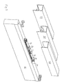
- FIG. 3 shows some illustrations for use on the upper edge of a sliding door 31.
- the damping device according to the FIGS. 1 and 2 shown in perspective, on a low mounting plate 30th
- rollers that support the sliding door 31 not only laterally, but also carry vertically can be provided, as shown on the left front. They can, for example, run in a rail profile 33 with somewhat inwardly angled running surfaces (for centering) or, in the case of a radially adapted roll size, also in the rail 34 shown on the right. In the rail 34, the rollers run on the bottom of each taken (upright) U-shaped lower leg ends of the total (inversely) U-shaped rail profile. As a result, a lateral guidance is possible.
- the rails 33 and 34 are shown here with extended front leg. Instead, additional blind rails may be applied, the vertical spacing of the rollers from the upper edge of the door member 31 could be reduced and / or the thickness of the mounting plate 30 could be increased.
- the second right-hand roller version is for lateral support only, but does not support the vertical gravity of the sliding door 31. It fits the 35 rail profile on the right. In this case, the sliding door 31 would run on rollers mounted below it in the floor area. The only laterally leading rollers can continue to run above in the rail 35, so that no leg extension is necessary. Lateral guidance is also possible with sliding surfaces instead of rollers.
- All rail profiles cover the damping device and the rollers in a particularly favorable manner against glances from the side and z. T. also from below, wherein the damping device and the rollers between the rail legs and between the rail base and the sliding door 31 are housed.
- the damping device may also be mounted outside of the rollers and fastened with mounting plates outside the rails, for example on opposite door pillars or walls.
- FIG. 4 shows again in a single representation a sequence of movements according to the FIGS. 1 and 2 , but with reference to a second embodiment. This differs from the first embodiment only by the configuration of the coupling on the slide 5.
- a single fixed pin 1 c instead of the levers 1a and 1b from the FIGS. 1 and 2
- a fork-like structure 2a and 2b is provided, which defines a recess for receiving the pin 1c.
- FIG. 5 shows accordingly a reverse movement, in which the pin 1 c abuts against the right part 2b of the fork seat when the sliding door is moved from the right to the left.
- the slider 5 is released from the angled position and comes again in positive connection with the pin 1c.
- This form fit now ensures that regardless of the residual swing of the sliding door. that it is driven solely by the force of the tensioned right spring 8b in the center position, wherein the right damper attenuates.
- the residual swing of the sliding door is large enough to provide for an over this middle position driving out, basically the same damping effect occurs as in FIG. 1 shown.
- the previous embodiments have two counter-rotating and each damping in one direction linear damper.
- the Figures 6a and 6b Variants show this as the third and fourth constitusbefsplel.
- the right damper is omitted and instead left the same double-acting linear damper used.
- Its piston 10 is equipped with two sealing lips, which correspond to the first and secondmonysbelsplel, but are provided double and antisymmetric, so that the piston is sealed in both directions of movement.
- the damper in the Figures 6a and 6b another also shown only symbolically valve 11 at its proximal end and thus acts in both directions. It is easy to see that a double-acting damper replaces the two single-acting dampers. For the rest, the above explanations apply.
Priority Applications (1)
| Application Number | Priority Date | Filing Date | Title |
|---|---|---|---|
| PL10013975T PL2333218T3 (pl) | 2009-12-14 | 2010-10-26 | Urządzenie do amortyzowania ruchu względnego ruchomych części urządzeń, zwłaszcza drzwi przesuwnych |
Applications Claiming Priority (1)
| Application Number | Priority Date | Filing Date | Title |
|---|---|---|---|
| DE202009016834U DE202009016834U1 (de) | 2009-12-14 | 2009-12-14 | Einrichtung zum Dämpfen der Relativbewegung bewegter Vorrichtungsteile, insbesondere von Schiebetüren |
Publications (2)
| Publication Number | Publication Date |
|---|---|
| EP2333218A1 true EP2333218A1 (fr) | 2011-06-15 |
| EP2333218B1 EP2333218B1 (fr) | 2018-02-14 |
Family
ID=42114979
Family Applications (1)
| Application Number | Title | Priority Date | Filing Date |
|---|---|---|---|
| EP10013975.7A Active EP2333218B1 (fr) | 2009-12-14 | 2010-10-26 | Dispositif d'amortissement du mouvement relatif d'éléments mobiles, notamment de portes coulissantes |
Country Status (4)
| Country | Link |
|---|---|
| EP (1) | EP2333218B1 (fr) |
| DE (1) | DE202009016834U1 (fr) |
| ES (1) | ES2667843T3 (fr) |
| PL (1) | PL2333218T3 (fr) |
Cited By (6)
| Publication number | Priority date | Publication date | Assignee | Title |
|---|---|---|---|---|
| DE202011102428U1 (de) | 2011-06-22 | 2011-10-25 | Christian Krischke-Lengersdorf | Positionsrückführvorrichtung, insbesondere für Schiebetüren |
| EP2538010A1 (fr) | 2011-06-22 | 2012-12-26 | Krischke-Lengersdorf, Christian | Dispositif de retour de position, notamment pour portes coulissantes |
| CN103764933A (zh) * | 2011-08-16 | 2014-04-30 | 黑蒂赫-海因泽有限及两合公司 | 用于将可移动的家具部件缩回至中间位置的装置 |
| EP3147440A1 (fr) * | 2010-02-08 | 2017-03-29 | KARL SIMON GmbH & Co. KG | Dispositif d'insertion pour portes coulissantes |
| CN106869664A (zh) * | 2017-03-16 | 2017-06-20 | 广东图特家居科技股份有限公司 | 一种挂趟门两内门对碰阻尼系统 |
| WO2021104832A1 (fr) | 2019-11-27 | 2021-06-03 | Paul Hettich Gmbh & Co. Kg | Élément de meuble |
Families Citing this family (5)
| Publication number | Priority date | Publication date | Assignee | Title |
|---|---|---|---|---|
| DE202010007230U1 (de) * | 2010-05-27 | 2010-08-26 | Häfele GmbH & Co. KG | Bidirektionale Einzugsvorrichtung für eine mittlere Schiebetür |
| DE102011001749A1 (de) * | 2011-04-01 | 2012-10-04 | Karl Simon Gmbh & Co. Kg | Einzugvorrichtung |
| DE102011109718B4 (de) * | 2011-08-06 | 2016-06-16 | Hueck Gmbh & Co. Kg | Bremsvorrichtung für eine Schiebetür oder ein Schiebefenster, insbesondere Hebe-Schiebe-Tür, sowie Schiebetür oder Schiebefenster |
| DE102014225291B3 (de) * | 2014-12-09 | 2015-12-24 | Geze Gmbh | Vorrichtung zur Beeinflussung der Öffnungs- und/oder Schließbewegung eines Tür- oder Fensterflügels |
| JP7020828B2 (ja) * | 2017-09-11 | 2022-02-16 | 株式会社Lixil | ソフトクローズ機構及び引戸 |
Citations (2)
| Publication number | Priority date | Publication date | Assignee | Title |
|---|---|---|---|---|
| WO2006056606A1 (fr) | 2004-11-26 | 2006-06-01 | Christian Krischke-Lengersdorf | Amortisseur pneumatique |
| WO2006105660A1 (fr) | 2005-04-05 | 2006-10-12 | Google Inc. | Procede et systeme prenant en charge le signalement verifie d’impressions publicitaires a partir de jeux video |
Family Cites Families (3)
| Publication number | Priority date | Publication date | Assignee | Title |
|---|---|---|---|---|
| DE2818439A1 (de) * | 1978-04-27 | 1979-11-08 | Magnetic Elektromotoren Gmbh | Antrieb fuer tueren u.dgl. |
| DE10019738C1 (de) * | 2000-04-20 | 2001-08-30 | Edscha Ag | Antreibbares Klappenscharnier |
| EP1662170B1 (fr) | 2004-11-26 | 2008-06-25 | Christian Krischke-Lengersdorf | Amortisseur pneumatique |
-
2009
- 2009-12-14 DE DE202009016834U patent/DE202009016834U1/de not_active Expired - Lifetime
-
2010
- 2010-10-26 PL PL10013975T patent/PL2333218T3/pl unknown
- 2010-10-26 EP EP10013975.7A patent/EP2333218B1/fr active Active
- 2010-10-26 ES ES10013975.7T patent/ES2667843T3/es active Active
Patent Citations (2)
| Publication number | Priority date | Publication date | Assignee | Title |
|---|---|---|---|---|
| WO2006056606A1 (fr) | 2004-11-26 | 2006-06-01 | Christian Krischke-Lengersdorf | Amortisseur pneumatique |
| WO2006105660A1 (fr) | 2005-04-05 | 2006-10-12 | Google Inc. | Procede et systeme prenant en charge le signalement verifie d’impressions publicitaires a partir de jeux video |
Cited By (9)
| Publication number | Priority date | Publication date | Assignee | Title |
|---|---|---|---|---|
| EP3147440A1 (fr) * | 2010-02-08 | 2017-03-29 | KARL SIMON GmbH & Co. KG | Dispositif d'insertion pour portes coulissantes |
| EP2534326B1 (fr) * | 2010-02-08 | 2019-05-15 | Karl Simon GmbH & Co. Kg | Dispositif d'escamotage pour portes coulissants |
| DE202011102428U1 (de) | 2011-06-22 | 2011-10-25 | Christian Krischke-Lengersdorf | Positionsrückführvorrichtung, insbesondere für Schiebetüren |
| EP2538010A1 (fr) | 2011-06-22 | 2012-12-26 | Krischke-Lengersdorf, Christian | Dispositif de retour de position, notamment pour portes coulissantes |
| CN103764933A (zh) * | 2011-08-16 | 2014-04-30 | 黑蒂赫-海因泽有限及两合公司 | 用于将可移动的家具部件缩回至中间位置的装置 |
| JP2014527438A (ja) * | 2011-08-16 | 2014-10-16 | ヘティッヒ‐ハインゼ ゲーエムベーハー ウント ツェーオー. カーゲー | 移動可能な家具部分を中間位置に引き込む装置 |
| CN106869664A (zh) * | 2017-03-16 | 2017-06-20 | 广东图特家居科技股份有限公司 | 一种挂趟门两内门对碰阻尼系统 |
| CN106869664B (zh) * | 2017-03-16 | 2024-03-22 | 广东图特精密五金科技股份有限公司 | 一种挂趟门两内门对碰阻尼系统 |
| WO2021104832A1 (fr) | 2019-11-27 | 2021-06-03 | Paul Hettich Gmbh & Co. Kg | Élément de meuble |
Also Published As
| Publication number | Publication date |
|---|---|
| PL2333218T3 (pl) | 2018-07-31 |
| ES2667843T3 (es) | 2018-05-14 |
| EP2333218B1 (fr) | 2018-02-14 |
| DE202009016834U1 (de) | 2010-04-22 |
Similar Documents
| Publication | Publication Date | Title |
|---|---|---|
| EP2333218B1 (fr) | Dispositif d'amortissement du mouvement relatif d'éléments mobiles, notamment de portes coulissantes | |
| EP1841982B1 (fr) | Système pour porte coulissant | |
| DE102013114309A1 (de) | Einzugs- und Dämpfungseinheit für ein Schiebeelement | |
| EP2390448A1 (fr) | Dispositif de rétraction bidirectionnel pour porte coulissante médiane | |
| DE202017100244U1 (de) | Duschabtrennung mit einer durch eine Feder-Dämpfer-Einheit aktiv in die Endstellungen bewegbaren Schiebetür | |
| DE202010004307U1 (de) | Verschlussanordnung | |
| DE102007059575A1 (de) | Dämpfungs- und Einzugseinrichtung für mindestens ein Schiebeelement, z.B. eine Schiebetür | |
| DE202016105495U1 (de) | Beschlag für verschiebbare plattenförmige Elemente mit Dämpfungsfunktion | |
| EP2992156B1 (fr) | Système de guidage d'une porte coulissante, porte coulissante et meuble | |
| EP2730734A2 (fr) | Dispositif d'insertion bidirectionnel pour une porte coulissante moyenne | |
| EP2365168B1 (fr) | Ferrure pour freiner le mouvement relatif d'éléments de dispositif, notamment de portes coulissantes | |
| EP3045643B1 (fr) | Vantail de porte | |
| DE202005017068U1 (de) | Schiebetürsystem mit Dämpfer | |
| EP2739807B1 (fr) | Système de ferrure pour le guidage d'un volet de fermeture d'un meuble | |
| DE202012002884U1 (de) | Dämpfersystem | |
| DE102010030710A1 (de) | Türanlage | |
| DE102018202813B3 (de) | Mechanischer Auslöser | |
| DE102016202377A1 (de) | Beschlaganordnung zur Anbindung eines schieb- und kippbaren Flügels | |
| DE202009006931U1 (de) | Druckfluidlineardämpfer mit Federmechanismus | |
| EP2366858A2 (fr) | Dispositif destiné à fermer une ouverture | |
| DE102010061137A1 (de) | Duschtrennwand oder -kabine | |
| DE102008047757B4 (de) | Vorrichtung zum Verschließen einer Öffnung | |
| EP2251518B1 (fr) | Amortisseur linéaire de fluide sous pression doté d'un mécanisme d'arrêt | |
| DE202009006939U1 (de) | Druckfluidlineardämpfer mit Rastmechanismus | |
| EP1798361A2 (fr) | Porte |
Legal Events
| Date | Code | Title | Description |
|---|---|---|---|
| PUAI | Public reference made under article 153(3) epc to a published international application that has entered the european phase |
Free format text: ORIGINAL CODE: 0009012 |
|
| AK | Designated contracting states |
Kind code of ref document: A1 Designated state(s): AL AT BE BG CH CY CZ DE DK EE ES FI FR GB GR HR HU IE IS IT LI LT LU LV MC MK MT NL NO PL PT RO RS SE SI SK SM TR |
|
| 17P | Request for examination filed |
Effective date: 20111215 |
|
| 17Q | First examination report despatched |
Effective date: 20120502 |
|
| APBK | Appeal reference recorded |
Free format text: ORIGINAL CODE: EPIDOSNREFNE |
|
| APBN | Date of receipt of notice of appeal recorded |
Free format text: ORIGINAL CODE: EPIDOSNNOA2E |
|
| APBR | Date of receipt of statement of grounds of appeal recorded |
Free format text: ORIGINAL CODE: EPIDOSNNOA3E |
|
| APAF | Appeal reference modified |
Free format text: ORIGINAL CODE: EPIDOSCREFNE |
|
| APBT | Appeal procedure closed |
Free format text: ORIGINAL CODE: EPIDOSNNOA9E |
|
| REG | Reference to a national code |
Ref country code: DE Ref legal event code: R079 Ref document number: 502010014641 Country of ref document: DE Free format text: PREVIOUS MAIN CLASS: E05F0005000000 Ipc: E05F0001160000 |
|
| RIC1 | Information provided on ipc code assigned before grant |
Ipc: E05F 1/16 20060101AFI20170620BHEP |
|
| GRAP | Despatch of communication of intention to grant a patent |
Free format text: ORIGINAL CODE: EPIDOSNIGR1 |
|
| STAA | Information on the status of an ep patent application or granted ep patent |
Free format text: STATUS: GRANT OF PATENT IS INTENDED |
|
| INTG | Intention to grant announced |
Effective date: 20170825 |
|
| GRAS | Grant fee paid |
Free format text: ORIGINAL CODE: EPIDOSNIGR3 |
|
| GRAA | (expected) grant |
Free format text: ORIGINAL CODE: 0009210 |
|
| STAA | Information on the status of an ep patent application or granted ep patent |
Free format text: STATUS: THE PATENT HAS BEEN GRANTED |
|
| AK | Designated contracting states |
Kind code of ref document: B1 Designated state(s): AL AT BE BG CH CY CZ DE DK EE ES FI FR GB GR HR HU IE IS IT LI LT LU LV MC MK MT NL NO PL PT RO RS SE SI SK SM TR |
|
| REG | Reference to a national code |
Ref country code: GB Ref legal event code: FG4D Free format text: NOT ENGLISH |
|
| REG | Reference to a national code |
Ref country code: CH Ref legal event code: EP |
|
| REG | Reference to a national code |
Ref country code: IE Ref legal event code: FG4D Free format text: LANGUAGE OF EP DOCUMENT: GERMAN |
|
| REG | Reference to a national code |
Ref country code: DE Ref legal event code: R096 Ref document number: 502010014641 Country of ref document: DE Ref country code: AT Ref legal event code: REF Ref document number: 969942 Country of ref document: AT Kind code of ref document: T Effective date: 20180315 |
|
| REG | Reference to a national code |
Ref country code: CH Ref legal event code: NV Representative=s name: E. BLUM AND CO. AG PATENT- UND MARKENANWAELTE , CH |
|
| REG | Reference to a national code |
Ref country code: ES Ref legal event code: FG2A Ref document number: 2667843 Country of ref document: ES Kind code of ref document: T3 Effective date: 20180514 |
|
| REG | Reference to a national code |
Ref country code: NL Ref legal event code: MP Effective date: 20180214 |
|
| PG25 | Lapsed in a contracting state [announced via postgrant information from national office to epo] |
Ref country code: FI Free format text: LAPSE BECAUSE OF FAILURE TO SUBMIT A TRANSLATION OF THE DESCRIPTION OR TO PAY THE FEE WITHIN THE PRESCRIBED TIME-LIMIT Effective date: 20180214 Ref country code: NO Free format text: LAPSE BECAUSE OF FAILURE TO SUBMIT A TRANSLATION OF THE DESCRIPTION OR TO PAY THE FEE WITHIN THE PRESCRIBED TIME-LIMIT Effective date: 20180514 Ref country code: LT Free format text: LAPSE BECAUSE OF FAILURE TO SUBMIT A TRANSLATION OF THE DESCRIPTION OR TO PAY THE FEE WITHIN THE PRESCRIBED TIME-LIMIT Effective date: 20180214 Ref country code: HR Free format text: LAPSE BECAUSE OF FAILURE TO SUBMIT A TRANSLATION OF THE DESCRIPTION OR TO PAY THE FEE WITHIN THE PRESCRIBED TIME-LIMIT Effective date: 20180214 Ref country code: NL Free format text: LAPSE BECAUSE OF FAILURE TO SUBMIT A TRANSLATION OF THE DESCRIPTION OR TO PAY THE FEE WITHIN THE PRESCRIBED TIME-LIMIT Effective date: 20180214 Ref country code: CY Free format text: LAPSE BECAUSE OF FAILURE TO SUBMIT A TRANSLATION OF THE DESCRIPTION OR TO PAY THE FEE WITHIN THE PRESCRIBED TIME-LIMIT Effective date: 20180214 |
|
| PG25 | Lapsed in a contracting state [announced via postgrant information from national office to epo] |
Ref country code: GR Free format text: LAPSE BECAUSE OF FAILURE TO SUBMIT A TRANSLATION OF THE DESCRIPTION OR TO PAY THE FEE WITHIN THE PRESCRIBED TIME-LIMIT Effective date: 20180515 Ref country code: LV Free format text: LAPSE BECAUSE OF FAILURE TO SUBMIT A TRANSLATION OF THE DESCRIPTION OR TO PAY THE FEE WITHIN THE PRESCRIBED TIME-LIMIT Effective date: 20180214 Ref country code: SE Free format text: LAPSE BECAUSE OF FAILURE TO SUBMIT A TRANSLATION OF THE DESCRIPTION OR TO PAY THE FEE WITHIN THE PRESCRIBED TIME-LIMIT Effective date: 20180214 Ref country code: RS Free format text: LAPSE BECAUSE OF FAILURE TO SUBMIT A TRANSLATION OF THE DESCRIPTION OR TO PAY THE FEE WITHIN THE PRESCRIBED TIME-LIMIT Effective date: 20180214 Ref country code: BG Free format text: LAPSE BECAUSE OF FAILURE TO SUBMIT A TRANSLATION OF THE DESCRIPTION OR TO PAY THE FEE WITHIN THE PRESCRIBED TIME-LIMIT Effective date: 20180514 |
|
| PG25 | Lapsed in a contracting state [announced via postgrant information from national office to epo] |
Ref country code: MT Free format text: LAPSE BECAUSE OF FAILURE TO SUBMIT A TRANSLATION OF THE DESCRIPTION OR TO PAY THE FEE WITHIN THE PRESCRIBED TIME-LIMIT Effective date: 20180214 |
|
| REG | Reference to a national code |
Ref country code: FR Ref legal event code: PLFP Year of fee payment: 9 |
|
| PG25 | Lapsed in a contracting state [announced via postgrant information from national office to epo] |
Ref country code: IT Free format text: LAPSE BECAUSE OF FAILURE TO SUBMIT A TRANSLATION OF THE DESCRIPTION OR TO PAY THE FEE WITHIN THE PRESCRIBED TIME-LIMIT Effective date: 20180214 Ref country code: RO Free format text: LAPSE BECAUSE OF FAILURE TO SUBMIT A TRANSLATION OF THE DESCRIPTION OR TO PAY THE FEE WITHIN THE PRESCRIBED TIME-LIMIT Effective date: 20180214 Ref country code: EE Free format text: LAPSE BECAUSE OF FAILURE TO SUBMIT A TRANSLATION OF THE DESCRIPTION OR TO PAY THE FEE WITHIN THE PRESCRIBED TIME-LIMIT Effective date: 20180214 Ref country code: AL Free format text: LAPSE BECAUSE OF FAILURE TO SUBMIT A TRANSLATION OF THE DESCRIPTION OR TO PAY THE FEE WITHIN THE PRESCRIBED TIME-LIMIT Effective date: 20180214 |
|
| REG | Reference to a national code |
Ref country code: DE Ref legal event code: R097 Ref document number: 502010014641 Country of ref document: DE |
|
| PG25 | Lapsed in a contracting state [announced via postgrant information from national office to epo] |
Ref country code: CZ Free format text: LAPSE BECAUSE OF FAILURE TO SUBMIT A TRANSLATION OF THE DESCRIPTION OR TO PAY THE FEE WITHIN THE PRESCRIBED TIME-LIMIT Effective date: 20180214 Ref country code: DK Free format text: LAPSE BECAUSE OF FAILURE TO SUBMIT A TRANSLATION OF THE DESCRIPTION OR TO PAY THE FEE WITHIN THE PRESCRIBED TIME-LIMIT Effective date: 20180214 Ref country code: SM Free format text: LAPSE BECAUSE OF FAILURE TO SUBMIT A TRANSLATION OF THE DESCRIPTION OR TO PAY THE FEE WITHIN THE PRESCRIBED TIME-LIMIT Effective date: 20180214 Ref country code: SK Free format text: LAPSE BECAUSE OF FAILURE TO SUBMIT A TRANSLATION OF THE DESCRIPTION OR TO PAY THE FEE WITHIN THE PRESCRIBED TIME-LIMIT Effective date: 20180214 |
|
| PLBE | No opposition filed within time limit |
Free format text: ORIGINAL CODE: 0009261 |
|
| STAA | Information on the status of an ep patent application or granted ep patent |
Free format text: STATUS: NO OPPOSITION FILED WITHIN TIME LIMIT |
|
| 26N | No opposition filed |
Effective date: 20181115 |
|
| PG25 | Lapsed in a contracting state [announced via postgrant information from national office to epo] |
Ref country code: SI Free format text: LAPSE BECAUSE OF FAILURE TO SUBMIT A TRANSLATION OF THE DESCRIPTION OR TO PAY THE FEE WITHIN THE PRESCRIBED TIME-LIMIT Effective date: 20180214 |
|
| REG | Reference to a national code |
Ref country code: BE Ref legal event code: MM Effective date: 20181031 |
|
| PG25 | Lapsed in a contracting state [announced via postgrant information from national office to epo] |
Ref country code: LU Free format text: LAPSE BECAUSE OF NON-PAYMENT OF DUE FEES Effective date: 20181026 Ref country code: MC Free format text: LAPSE BECAUSE OF FAILURE TO SUBMIT A TRANSLATION OF THE DESCRIPTION OR TO PAY THE FEE WITHIN THE PRESCRIBED TIME-LIMIT Effective date: 20180214 |
|
| REG | Reference to a national code |
Ref country code: IE Ref legal event code: MM4A |
|
| PG25 | Lapsed in a contracting state [announced via postgrant information from national office to epo] |
Ref country code: BE Free format text: LAPSE BECAUSE OF NON-PAYMENT OF DUE FEES Effective date: 20181031 |
|
| PG25 | Lapsed in a contracting state [announced via postgrant information from national office to epo] |
Ref country code: IE Free format text: LAPSE BECAUSE OF NON-PAYMENT OF DUE FEES Effective date: 20181026 |
|
| PG25 | Lapsed in a contracting state [announced via postgrant information from national office to epo] |
Ref country code: TR Free format text: LAPSE BECAUSE OF FAILURE TO SUBMIT A TRANSLATION OF THE DESCRIPTION OR TO PAY THE FEE WITHIN THE PRESCRIBED TIME-LIMIT Effective date: 20180214 |
|
| PG25 | Lapsed in a contracting state [announced via postgrant information from national office to epo] |
Ref country code: PT Free format text: LAPSE BECAUSE OF FAILURE TO SUBMIT A TRANSLATION OF THE DESCRIPTION OR TO PAY THE FEE WITHIN THE PRESCRIBED TIME-LIMIT Effective date: 20180214 |
|
| PG25 | Lapsed in a contracting state [announced via postgrant information from national office to epo] |
Ref country code: HU Free format text: LAPSE BECAUSE OF FAILURE TO SUBMIT A TRANSLATION OF THE DESCRIPTION OR TO PAY THE FEE WITHIN THE PRESCRIBED TIME-LIMIT; INVALID AB INITIO Effective date: 20101026 Ref country code: MK Free format text: LAPSE BECAUSE OF NON-PAYMENT OF DUE FEES Effective date: 20180214 |
|
| PG25 | Lapsed in a contracting state [announced via postgrant information from national office to epo] |
Ref country code: IS Free format text: LAPSE BECAUSE OF FAILURE TO SUBMIT A TRANSLATION OF THE DESCRIPTION OR TO PAY THE FEE WITHIN THE PRESCRIBED TIME-LIMIT Effective date: 20180614 |
|
| PGFP | Annual fee paid to national office [announced via postgrant information from national office to epo] |
Ref country code: PL Payment date: 20221018 Year of fee payment: 13 |
|
| P01 | Opt-out of the competence of the unified patent court (upc) registered |
Effective date: 20230510 |
|
| PGFP | Annual fee paid to national office [announced via postgrant information from national office to epo] |
Ref country code: GB Payment date: 20231025 Year of fee payment: 14 |
|
| PGFP | Annual fee paid to national office [announced via postgrant information from national office to epo] |
Ref country code: ES Payment date: 20231117 Year of fee payment: 14 |
|
| PGFP | Annual fee paid to national office [announced via postgrant information from national office to epo] |
Ref country code: FR Payment date: 20231023 Year of fee payment: 14 Ref country code: DE Payment date: 20231018 Year of fee payment: 14 Ref country code: CH Payment date: 20231102 Year of fee payment: 14 Ref country code: AT Payment date: 20231019 Year of fee payment: 14 |
|
| PGFP | Annual fee paid to national office [announced via postgrant information from national office to epo] |
Ref country code: PL Payment date: 20231013 Year of fee payment: 14 |