EP2333218A1 - Device for damping the relative motion of moving parts, in particular sliding doors - Google Patents
Device for damping the relative motion of moving parts, in particular sliding doors Download PDFInfo
- Publication number
- EP2333218A1 EP2333218A1 EP20100013975 EP10013975A EP2333218A1 EP 2333218 A1 EP2333218 A1 EP 2333218A1 EP 20100013975 EP20100013975 EP 20100013975 EP 10013975 A EP10013975 A EP 10013975A EP 2333218 A1 EP2333218 A1 EP 2333218A1
- Authority
- EP
- European Patent Office
- Prior art keywords
- sliding door
- rail
- coupling
- sliding
- damper
- Prior art date
- Legal status (The legal status is an assumption and is not a legal conclusion. Google has not performed a legal analysis and makes no representation as to the accuracy of the status listed.)
- Granted
Links
- 238000013016 damping Methods 0.000 title claims description 44
- 230000008878 coupling Effects 0.000 claims description 27
- 238000010168 coupling process Methods 0.000 claims description 27
- 238000005859 coupling reaction Methods 0.000 claims description 27
- 230000000295 complement effect Effects 0.000 claims 1
- 230000003993 interaction Effects 0.000 claims 1
- 230000000694 effects Effects 0.000 description 5
- 238000010276 construction Methods 0.000 description 3
- 230000001419 dependent effect Effects 0.000 description 2
- 238000007789 sealing Methods 0.000 description 2
- 230000007704 transition Effects 0.000 description 2
- 230000000007 visual effect Effects 0.000 description 2
- 230000000903 blocking effect Effects 0.000 description 1
- 238000001816 cooling Methods 0.000 description 1
- 230000006866 deterioration Effects 0.000 description 1
- 230000002349 favourable effect Effects 0.000 description 1
- 230000005484 gravity Effects 0.000 description 1
- 238000004519 manufacturing process Methods 0.000 description 1
- 238000000034 method Methods 0.000 description 1
- JHJNPOSPVGRIAN-SFHVURJKSA-N n-[3-[(1s)-1-[[6-(3,4-dimethoxyphenyl)pyrazin-2-yl]amino]ethyl]phenyl]-5-methylpyridine-3-carboxamide Chemical compound C1=C(OC)C(OC)=CC=C1C1=CN=CC(N[C@@H](C)C=2C=C(NC(=O)C=3C=C(C)C=NC=3)C=CC=2)=N1 JHJNPOSPVGRIAN-SFHVURJKSA-N 0.000 description 1
- 230000035939 shock Effects 0.000 description 1
- 238000000638 solvent extraction Methods 0.000 description 1
- 210000001364 upper extremity Anatomy 0.000 description 1
Images


Classifications
-
- E—FIXED CONSTRUCTIONS
- E05—LOCKS; KEYS; WINDOW OR DOOR FITTINGS; SAFES
- E05F—DEVICES FOR MOVING WINGS INTO OPEN OR CLOSED POSITION; CHECKS FOR WINGS; WING FITTINGS NOT OTHERWISE PROVIDED FOR, CONCERNED WITH THE FUNCTIONING OF THE WING
- E05F5/00—Braking devices, e.g. checks; Stops; Buffers
- E05F5/003—Braking devices, e.g. checks; Stops; Buffers for sliding wings
-
- F—MECHANICAL ENGINEERING; LIGHTING; HEATING; WEAPONS; BLASTING
- F16—ENGINEERING ELEMENTS AND UNITS; GENERAL MEASURES FOR PRODUCING AND MAINTAINING EFFECTIVE FUNCTIONING OF MACHINES OR INSTALLATIONS; THERMAL INSULATION IN GENERAL
- F16F—SPRINGS; SHOCK-ABSORBERS; MEANS FOR DAMPING VIBRATION
- F16F9/00—Springs, vibration-dampers, shock-absorbers, or similarly-constructed movement-dampers using a fluid or the equivalent as damping medium
- F16F9/32—Details
- F16F9/48—Arrangements for providing different damping effects at different parts of the stroke
-
- E—FIXED CONSTRUCTIONS
- E05—LOCKS; KEYS; WINDOW OR DOOR FITTINGS; SAFES
- E05F—DEVICES FOR MOVING WINGS INTO OPEN OR CLOSED POSITION; CHECKS FOR WINGS; WING FITTINGS NOT OTHERWISE PROVIDED FOR, CONCERNED WITH THE FUNCTIONING OF THE WING
- E05F1/00—Closers or openers for wings, not otherwise provided for in this subclass
- E05F1/08—Closers or openers for wings, not otherwise provided for in this subclass spring-actuated, e.g. for horizontally sliding wings
- E05F1/16—Closers or openers for wings, not otherwise provided for in this subclass spring-actuated, e.g. for horizontally sliding wings for sliding wings
-
- E—FIXED CONSTRUCTIONS
- E05—LOCKS; KEYS; WINDOW OR DOOR FITTINGS; SAFES
- E05Y—INDEXING SCHEME RELATING TO HINGES OR OTHER SUSPENSION DEVICES FOR DOORS, WINDOWS OR WINGS AND DEVICES FOR MOVING WINGS INTO OPEN OR CLOSED POSITION, CHECKS FOR WINGS AND WING FITTINGS NOT OTHERWISE PROVIDED FOR, CONCERNED WITH THE FUNCTIONING OF THE WING
- E05Y2201/00—Constructional elements; Accessories therefore
- E05Y2201/20—Brakes; Disengaging means, e.g. clutches; Holders, e.g. locks; Stops; Accessories therefore
- E05Y2201/21—Brakes
-
- E—FIXED CONSTRUCTIONS
- E05—LOCKS; KEYS; WINDOW OR DOOR FITTINGS; SAFES
- E05Y—INDEXING SCHEME RELATING TO HINGES OR OTHER SUSPENSION DEVICES FOR DOORS, WINDOWS OR WINGS AND DEVICES FOR MOVING WINGS INTO OPEN OR CLOSED POSITION, CHECKS FOR WINGS AND WING FITTINGS NOT OTHERWISE PROVIDED FOR, CONCERNED WITH THE FUNCTIONING OF THE WING
- E05Y2201/00—Constructional elements; Accessories therefore
- E05Y2201/20—Brakes; Disengaging means, e.g. clutches; Holders, e.g. locks; Stops; Accessories therefore
- E05Y2201/214—Disengaging means
-
- E—FIXED CONSTRUCTIONS
- E05—LOCKS; KEYS; WINDOW OR DOOR FITTINGS; SAFES
- E05Y—INDEXING SCHEME RELATING TO HINGES OR OTHER SUSPENSION DEVICES FOR DOORS, WINDOWS OR WINGS AND DEVICES FOR MOVING WINGS INTO OPEN OR CLOSED POSITION, CHECKS FOR WINGS AND WING FITTINGS NOT OTHERWISE PROVIDED FOR, CONCERNED WITH THE FUNCTIONING OF THE WING
- E05Y2201/00—Constructional elements; Accessories therefore
- E05Y2201/20—Brakes; Disengaging means, e.g. clutches; Holders, e.g. locks; Stops; Accessories therefore
- E05Y2201/23—Actuation thereof
- E05Y2201/232—Actuation thereof by automatically acting means
- E05Y2201/24—Actuation thereof by automatically acting means using lost motion
-
- E—FIXED CONSTRUCTIONS
- E05—LOCKS; KEYS; WINDOW OR DOOR FITTINGS; SAFES
- E05Y—INDEXING SCHEME RELATING TO HINGES OR OTHER SUSPENSION DEVICES FOR DOORS, WINDOWS OR WINGS AND DEVICES FOR MOVING WINGS INTO OPEN OR CLOSED POSITION, CHECKS FOR WINGS AND WING FITTINGS NOT OTHERWISE PROVIDED FOR, CONCERNED WITH THE FUNCTIONING OF THE WING
- E05Y2201/00—Constructional elements; Accessories therefore
- E05Y2201/20—Brakes; Disengaging means, e.g. clutches; Holders, e.g. locks; Stops; Accessories therefore
- E05Y2201/252—Brakes; Disengaging means, e.g. clutches; Holders, e.g. locks; Stops; Accessories therefore characterised by type of friction
- E05Y2201/254—Fluid or viscous friction
-
- E—FIXED CONSTRUCTIONS
- E05—LOCKS; KEYS; WINDOW OR DOOR FITTINGS; SAFES
- E05Y—INDEXING SCHEME RELATING TO HINGES OR OTHER SUSPENSION DEVICES FOR DOORS, WINDOWS OR WINGS AND DEVICES FOR MOVING WINGS INTO OPEN OR CLOSED POSITION, CHECKS FOR WINGS AND WING FITTINGS NOT OTHERWISE PROVIDED FOR, CONCERNED WITH THE FUNCTIONING OF THE WING
- E05Y2201/00—Constructional elements; Accessories therefore
- E05Y2201/20—Brakes; Disengaging means, e.g. clutches; Holders, e.g. locks; Stops; Accessories therefore
- E05Y2201/262—Brakes; Disengaging means, e.g. clutches; Holders, e.g. locks; Stops; Accessories therefore characterised by type of motion
- E05Y2201/264—Brakes; Disengaging means, e.g. clutches; Holders, e.g. locks; Stops; Accessories therefore characterised by type of motion linear
-
- E—FIXED CONSTRUCTIONS
- E05—LOCKS; KEYS; WINDOW OR DOOR FITTINGS; SAFES
- E05Y—INDEXING SCHEME RELATING TO HINGES OR OTHER SUSPENSION DEVICES FOR DOORS, WINDOWS OR WINGS AND DEVICES FOR MOVING WINGS INTO OPEN OR CLOSED POSITION, CHECKS FOR WINGS AND WING FITTINGS NOT OTHERWISE PROVIDED FOR, CONCERNED WITH THE FUNCTIONING OF THE WING
- E05Y2600/00—Mounting or coupling arrangements for elements provided for in this subclass
- E05Y2600/40—Mounting location; Visibility of the elements
- E05Y2600/46—Mounting location; Visibility of the elements in or on the wing
-
- E—FIXED CONSTRUCTIONS
- E05—LOCKS; KEYS; WINDOW OR DOOR FITTINGS; SAFES
- E05Y—INDEXING SCHEME RELATING TO HINGES OR OTHER SUSPENSION DEVICES FOR DOORS, WINDOWS OR WINGS AND DEVICES FOR MOVING WINGS INTO OPEN OR CLOSED POSITION, CHECKS FOR WINGS AND WING FITTINGS NOT OTHERWISE PROVIDED FOR, CONCERNED WITH THE FUNCTIONING OF THE WING
- E05Y2800/00—Details, accessories and auxiliary operations not otherwise provided for
- E05Y2800/20—Combinations of elements
- E05Y2800/205—Combinations of elements forming a unit
-
- E—FIXED CONSTRUCTIONS
- E05—LOCKS; KEYS; WINDOW OR DOOR FITTINGS; SAFES
- E05Y—INDEXING SCHEME RELATING TO HINGES OR OTHER SUSPENSION DEVICES FOR DOORS, WINDOWS OR WINGS AND DEVICES FOR MOVING WINGS INTO OPEN OR CLOSED POSITION, CHECKS FOR WINGS AND WING FITTINGS NOT OTHERWISE PROVIDED FOR, CONCERNED WITH THE FUNCTIONING OF THE WING
- E05Y2800/00—Details, accessories and auxiliary operations not otherwise provided for
- E05Y2800/20—Combinations of elements
- E05Y2800/21—Combinations of elements of identical elements, e.g. of identical compression springs
-
- E—FIXED CONSTRUCTIONS
- E05—LOCKS; KEYS; WINDOW OR DOOR FITTINGS; SAFES
- E05Y—INDEXING SCHEME RELATING TO HINGES OR OTHER SUSPENSION DEVICES FOR DOORS, WINDOWS OR WINGS AND DEVICES FOR MOVING WINGS INTO OPEN OR CLOSED POSITION, CHECKS FOR WINGS AND WING FITTINGS NOT OTHERWISE PROVIDED FOR, CONCERNED WITH THE FUNCTIONING OF THE WING
- E05Y2800/00—Details, accessories and auxiliary operations not otherwise provided for
- E05Y2800/20—Combinations of elements
- E05Y2800/23—Combinations of elements of elements of different categories
- E05Y2800/24—Combinations of elements of elements of different categories of springs and brakes
-
- E—FIXED CONSTRUCTIONS
- E05—LOCKS; KEYS; WINDOW OR DOOR FITTINGS; SAFES
- E05Y—INDEXING SCHEME RELATING TO HINGES OR OTHER SUSPENSION DEVICES FOR DOORS, WINDOWS OR WINGS AND DEVICES FOR MOVING WINGS INTO OPEN OR CLOSED POSITION, CHECKS FOR WINGS AND WING FITTINGS NOT OTHERWISE PROVIDED FOR, CONCERNED WITH THE FUNCTIONING OF THE WING
- E05Y2800/00—Details, accessories and auxiliary operations not otherwise provided for
- E05Y2800/20—Combinations of elements
- E05Y2800/242—Combinations of elements arranged in parallel relationship
-
- E—FIXED CONSTRUCTIONS
- E05—LOCKS; KEYS; WINDOW OR DOOR FITTINGS; SAFES
- E05Y—INDEXING SCHEME RELATING TO HINGES OR OTHER SUSPENSION DEVICES FOR DOORS, WINDOWS OR WINGS AND DEVICES FOR MOVING WINGS INTO OPEN OR CLOSED POSITION, CHECKS FOR WINGS AND WING FITTINGS NOT OTHERWISE PROVIDED FOR, CONCERNED WITH THE FUNCTIONING OF THE WING
- E05Y2800/00—Details, accessories and auxiliary operations not otherwise provided for
- E05Y2800/20—Combinations of elements
- E05Y2800/244—Combinations of elements arranged in serial relationship
-
- E—FIXED CONSTRUCTIONS
- E05—LOCKS; KEYS; WINDOW OR DOOR FITTINGS; SAFES
- E05Y—INDEXING SCHEME RELATING TO HINGES OR OTHER SUSPENSION DEVICES FOR DOORS, WINDOWS OR WINGS AND DEVICES FOR MOVING WINGS INTO OPEN OR CLOSED POSITION, CHECKS FOR WINGS AND WING FITTINGS NOT OTHERWISE PROVIDED FOR, CONCERNED WITH THE FUNCTIONING OF THE WING
- E05Y2800/00—Details, accessories and auxiliary operations not otherwise provided for
- E05Y2800/73—Single use of elements
-
- E—FIXED CONSTRUCTIONS
- E05—LOCKS; KEYS; WINDOW OR DOOR FITTINGS; SAFES
- E05Y—INDEXING SCHEME RELATING TO HINGES OR OTHER SUSPENSION DEVICES FOR DOORS, WINDOWS OR WINGS AND DEVICES FOR MOVING WINGS INTO OPEN OR CLOSED POSITION, CHECKS FOR WINGS AND WING FITTINGS NOT OTHERWISE PROVIDED FOR, CONCERNED WITH THE FUNCTIONING OF THE WING
- E05Y2800/00—Details, accessories and auxiliary operations not otherwise provided for
- E05Y2800/74—Specific positions
- E05Y2800/75—Specific positions intermediate
-
- E—FIXED CONSTRUCTIONS
- E05—LOCKS; KEYS; WINDOW OR DOOR FITTINGS; SAFES
- E05Y—INDEXING SCHEME RELATING TO HINGES OR OTHER SUSPENSION DEVICES FOR DOORS, WINDOWS OR WINGS AND DEVICES FOR MOVING WINGS INTO OPEN OR CLOSED POSITION, CHECKS FOR WINGS AND WING FITTINGS NOT OTHERWISE PROVIDED FOR, CONCERNED WITH THE FUNCTIONING OF THE WING
- E05Y2900/00—Application of doors, windows, wings or fittings thereof
- E05Y2900/20—Application of doors, windows, wings or fittings thereof for furnitures, e.g. cabinets
Definitions
- the present invention relates to a damping device with which relative movements between device parts to be damped, in particular movements of sliding doors or other doors or furniture parts.
- furniture parts such as flaps, drawers or doors, in particular cabinet doors and furniture-independent doors, such as room partitioning systems come into consideration.
- cooling facilities. z. B_ in large grocery stores and supermarkets, may have corresponding door systems, in particular, of course, sliding door systems.
- the invention is based on the technical problem to find extended applications for a damping device.
- the invention is directed to a device for damping the relative movement of moving parts of a device with a damper, a coupling for making and releasing a frictional connection between a first of the device parts and one end of the damper, wherein another end of the damper is coupled to a second of the device location, so that the damper in the closed state of the coupling dampens a relative movement between the two device parts, and wherein the two device parts are movable in two opposite directions to each other, characterized in that the clutch can be solved in relative directions of the two parts of the device in both directions, and on a thus designed sliding door system and the use of the damping device for this purpose.
- a basic idea of the invention is to provide the damping device with a coupling which can be released in relative movements in two opposite directions.
- the coupling parts and preferably then also the moving parts of the device, can move away from each other in both directions.
- the damping device can thus be arranged in particular in a middle position of a total movement distance.
- the term "middle” does not necessarily mean that the remaining movement distances in both directions are about the same length. It is only a question of movement paths still existing in both directions, ie the damping device is not used in conjunction with an end position. In the known state of the art, however, various types of damping devices are described which relate precisely to this approach to an end position.
- the invention provides new uses, such as by a sliding door in a certain position closes an opening or concealed and can be moved out of this position to two sides. It could, for example, be a middle element of a multi-part sliding door system.
- the damping device can then attenuate the (initial) moving out of the sliding door element from the middle position and / or driving into this position and / or the driving out beyond the position, which will be discussed in more detail in connection with the embodiments.
- it is especially thought that the damping effect occurs only for a comparatively small part of the movement distances of the device part occurring here, in this case the sliding door element.
- the damper itself may preferably be a linear damper and also preferably a pneumatic damper, to which reference is already made WO 2006/056606 can be referenced.
- the coupling preferably works mechanically, in particular by a physical stop or a positive connection or a combination of both. It therefore preferably dispenses with non-mechanical couplings, such as magnetic couplings.
- the coupling has a designated here as a slider element that can be moved along a certain distance and can reach a release position in at least one angled end of such a sliding distance.
- the clutch is thus released, and preferably by the retraction into the release position itself.
- a pin can thus move out of an area in which he can encounter a stop, or can a mechanical coupling, such as be moved out of such a range by positive locking, producing element out or in its orientation so changed (tilted) that a release is possible.
- a pin can thus move out of an area in which he can encounter a stop, or can a mechanical coupling, such as be moved out of such a range by positive locking, producing element out or in its orientation so changed (tilted) that a release is possible.
- the coupling may have a stop element, in particular on the non-damper-carrying device part, which is held firmly to one side and yielding to another side, so to speak acts as a directional stop.
- a stop element in particular on the non-damper-carrying device part, which is held firmly to one side and yielding to another side, so to speak acts as a directional stop.
- it may be a lever that strikes in an articulated bearing in one direction and can dodge in another direction.
- the second arm can serve for striking in the sense of blocking the stop element and the first arm for striking a further coupling element, wherein the two lever arms can, for example, run at an angle, in particular at right angles.
- the already mentioned slider is forked, so has a recess between two protruding parts, and should embrace a stop element with this fork-like recess.
- elastic means preferably springs.
- spring is meant a spring element constructed of conventional metallic spring material, in particular a helical spring. Rubber elastic or other elastic elements should be included in the term “elastic device” but not in the term “spring.”
- the elastic device allows a coupling part, in particular the slider, to move out of a release position and / or into the middle position along a sliding path reset (although the middle position again does not necessarily have to be symmetrical in the middle).
- two coil springs arranged on both sides of the slide and coupled to it can be used which, in the force-free state of the slide, predetermine a middle position, at least one of the springs being stretched elastically on movement thereof out of the way.
- the coupling entrains the two device parts, that is, the spring loading ensures a position adjustment between the device parts.
- this is not mandatory.
- the clutch can also solve this, for which reference is made to the embodiments in comparison with each other.
- Sliding door systems are used in furniture construction, in room or front doors, in room parts, also for the demarcation of walk-in cabinets, refrigerators or rooms, but also for larger hall doors, garage doors u. ⁇ .
- the sliding door elements to be moved are heavy.
- the invention is also directed to a sliding door system with a damping device as described above, which is mounted in particular on the one hand on a rail for holding and on the other hand on the sliding door element, wherein the damper is mounted within the rail so that it by the rail in the covered on the Schlezutelement vertical viewing direction.
- the basic idea is that the most common sliding door systems anyway provided rails that not only hold the sliding door element, but also include and cover with a rail leg at least a space above the corresponding side edge of the sliding door element.
- the viewing direction on the sliding door element that is perpendicular with respect to its areal extension, meant.
- “Hold” here does not necessarily mean that the rail carries the entire weight or even only the weight of the sliding door elements, but also refers to such cases in which the rail, for example, only against unwanted lateral movements, so to speak in the mentioned direction, is provided and insofar holds the sliding door element in the track.
- the rail can with its leg cover the side edge itself and cover or, as seen in the horizontal direction, substantially connect to the side edge. Then it covers a space above the side edge, which may be used for mounting element and the like. Use and therefore should be protected from view. Of course, there may be a small slot, so that the term covering only in the sense of a substantially covering is to be understood.
- this rail is also used to cover the damping device itself by this is arranged within the rail, so the otherwise observed in the market deterioration of the appearance by damper constructions are avoidable.
- the rail must at most have slightly larger dimensions than otherwise necessary.
- slim designs of the damper are possible, in particular the linear cylinders, which can be readily installed in existing standard rail systems.
- the damping device can be mounted in a limited by the rail itself at best in terms of the available volume (or the width and height) way and connected to the rail and the sliding door. If desired, elaborate housing constructions, in..other cases, for aesthetic reasons, due the otherwise not given protection against contact or for other reasons may be required, be omitted.
- the damping device between the rail and the Schleizürelement is mounted. This is not necessary.
- an inverted L-profit that is horizontally mounted on a ceiling with one leg and covers with the other vertical leg in the manner described at least the space above the side edge, and also thinks this L-profile in front of a wall So mounted in a corner, so the damping device could also be quite appropriate between the Schleizürelement and the wall of the room.
- the rail may include bearings for supporting the sliding door member in the slidable manner in the rail, such as systems having guide rollers and treads therefor. This applies both to the already mentioned case that the holding by the rail corresponds only to a lateral guiding in a web, as well as in the case of a support of a part of or the entire weight of the sliding door element.
- the Dämpfungseinnchtung is mounted in a solution according to the invention in an upper rail, although sliding door systems usually also additionally have lower rails in the bottom area.
- the bottom Rails are a minimal size and therefore often no additional mechanical effort desired. Furthermore, they are particularly well accessible even when viewed from above, when there is a visual coverage in the (horizontal) direction perpendicular to the sliding door element level.
- FIG. 1 shows in six from top to bottom consecutive individual representations schematically a movement of a damping device according to the invention.
- the movement takes place in the drawing plane horizontally from right to left, as indicated by the arrow, with only the last representation means a reverse movement in contrast.
- In the upper area of each individual representation is shaded part of a based FIG. 3 shown in more detail to explanatory mounting rail. It could also be a ceiling.
- To this two two-armed levers 1a and 1b are articulated, as the individual representations show in comparison for the right lever 1 b, the movement shown is reversed also for the left lever 1 a is possible. It can be seen that the right lever 1b can be turned clockwise by about 90 °. In the opposite direction would be in the top single view horizontal standing shorter second lever arm strike and lock such a reverse movement.
- the left lever 1a is exactly the opposite.
- Both levers 1a and 1b form jewells stop elements for a pin 2, which protrudes from a hereinafter explained in more detail damping device upwards, which in turn is mounted on a moving in the sequence of the individual representations from right to left sliding door.
- the comparison of the individual representations shows that this pin 2 in the illustrated movement first pushes the lever 1 b upwards, then to run against the lever 1a as a stop.
- the damping device has two counter-rotating individual pneumatic linear damper 3a and 3b.
- an elastomeric valve located at the respective outer end of the damper 3a and 3b, an elastomeric valve throttles out of the respective cylinder interior to the outside urgent air movements and thus one after each outwardly directed movement of the respective piston rod 4a and 4b attenuates. Respective internal movements are much less damped, because on the piston itself, a sealing lip opening slightly in this direction is provided.
- the piston rods 4a and 4b are recognizably coupled to one another in the illustrations and are fastened to a centrally arranged slide 5.
- This slider 5 has the already mentioned pin 2 and is guided by way of two provided at its horizontal outer ends bearing pins in a sliding guide 6, which defines a sliding distance.
- the slotted guide 6 and the sliding path defined thereby have at their outer ends at an angle kinking sections which define a release position of the slider 5 as the end pieces. This is based on FIG. 2 discussed in more detail.
- the sliding door is moved from the right to the levers 1 a and 1 b is moved, wherein the slider is held in a central position and the spring forces of the springs 8 a and 8 b compensate.
- the pistons of the two dampers are approximately in a middle position, the pin 2 moves past the right stop lever 1 b and pushes in the fourth individual view against the left lever 1 a.
- the inertia of the sliding door leads in the transition to the fifth individual representation to the fact that the slider is moved along the straight part of the sliding distance, wherein the left spring 8a is tensioned. This movement is damped by the right damper by pushing the piston rod 4b into the corresponding cylinder.
- the damping device according to the invention thus has the effect here, an inertia-related Movement of the sliding door on the position in which the pin 2 is arranged at the middle position of the slider 5 between the levers 1 a and 1 b, also to attenuate and also to dampen the return caused by the springs.
- FIG. 2 corresponds in the type of representation completely FIG. 1 ; it is also shown the same damping device as the first embodiment.
- the sequence of individual representations here shows a movement of the sliding door from the end of the movement sequence FIG. 1 reached position to the right.
- the pin 2 abuts right at the beginning, namely in the second individual representation, to the right lever 1 b.
- the slider 5 is first moved along the straight portion of the sliding distance, as the second individual view shows.
- the slider must be up to the tilted portion of the sliding distance, wherein only in the fourth individual view reaches the release position.
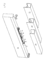
- FIG. 3 shows some illustrations for use on the upper edge of a sliding door 31.
- the damping device according to the FIGS. 1 and 2 shown in perspective, on a low mounting plate 30th
- rollers that support the sliding door 31 not only laterally, but also carry vertically can be provided, as shown on the left front. They can, for example, run in a rail profile 33 with somewhat inwardly angled running surfaces (for centering) or, in the case of a radially adapted roll size, also in the rail 34 shown on the right. In the rail 34, the rollers run on the bottom of each taken (upright) U-shaped lower leg ends of the total (inversely) U-shaped rail profile. As a result, a lateral guidance is possible.
- the rails 33 and 34 are shown here with extended front leg. Instead, additional blind rails may be applied, the vertical spacing of the rollers from the upper edge of the door member 31 could be reduced and / or the thickness of the mounting plate 30 could be increased.
- the second right-hand roller version is for lateral support only, but does not support the vertical gravity of the sliding door 31. It fits the 35 rail profile on the right. In this case, the sliding door 31 would run on rollers mounted below it in the floor area. The only laterally leading rollers can continue to run above in the rail 35, so that no leg extension is necessary. Lateral guidance is also possible with sliding surfaces instead of rollers.
- All rail profiles cover the damping device and the rollers in a particularly favorable manner against glances from the side and z. T. also from below, wherein the damping device and the rollers between the rail legs and between the rail base and the sliding door 31 are housed.
- the damping device may also be mounted outside of the rollers and fastened with mounting plates outside the rails, for example on opposite door pillars or walls.
- FIG. 4 shows again in a single representation a sequence of movements according to the FIGS. 1 and 2 , but with reference to a second embodiment. This differs from the first embodiment only by the configuration of the coupling on the slide 5.
- a single fixed pin 1 c instead of the levers 1a and 1b from the FIGS. 1 and 2
- a fork-like structure 2a and 2b is provided, which defines a recess for receiving the pin 1c.
- FIG. 5 shows accordingly a reverse movement, in which the pin 1 c abuts against the right part 2b of the fork seat when the sliding door is moved from the right to the left.
- the slider 5 is released from the angled position and comes again in positive connection with the pin 1c.
- This form fit now ensures that regardless of the residual swing of the sliding door. that it is driven solely by the force of the tensioned right spring 8b in the center position, wherein the right damper attenuates.
- the residual swing of the sliding door is large enough to provide for an over this middle position driving out, basically the same damping effect occurs as in FIG. 1 shown.
- the previous embodiments have two counter-rotating and each damping in one direction linear damper.
- the Figures 6a and 6b Variants show this as the third and fourth constitusbefsplel.
- the right damper is omitted and instead left the same double-acting linear damper used.
- Its piston 10 is equipped with two sealing lips, which correspond to the first and secondmonysbelsplel, but are provided double and antisymmetric, so that the piston is sealed in both directions of movement.
- the damper in the Figures 6a and 6b another also shown only symbolically valve 11 at its proximal end and thus acts in both directions. It is easy to see that a double-acting damper replaces the two single-acting dampers. For the rest, the above explanations apply.
Abstract
Description
Die vorliegende Erfindung bezieht sich auf eine Dämpfungseinrichtung, mit der Relativbewegungen zwischen Vorrichtungsteilen gedämpft werden sollen, insbesondere Bewegungen von Schiebetüren oder auch anderen Türen oder Möbelteilen. In Betracht kommen insbesondere Möbelteile wie Klappen, Schubladen oder Türen, insbesondere Schranktüren und auch von Möbeln unabhängige Türen, so etwa bei Raumteilungssystemen. Auch Kühleinrichtungen. z. B_ in großen Lebensmittelgeschäften und Supermärkten, können entsprechende Türsysteme, insbesondere natürlich Schiebetürsysteme, aufweisen.The present invention relates to a damping device with which relative movements between device parts to be damped, in particular movements of sliding doors or other doors or furniture parts. In particular, furniture parts such as flaps, drawers or doors, in particular cabinet doors and furniture-independent doors, such as room partitioning systems come into consideration. Also cooling facilities. z. B_ in large grocery stores and supermarkets, may have corresponding door systems, in particular, of course, sliding door systems.
Es ist an sich längst bekannt, Bewegungen mechanisch zu dämpfen, beispielsweise die Ein- und/oder Auszugsbewegungen einer Möbelschublade oder einer Schiebetür. Damit soll verhindert werden, dass eine Schublade oder Schiebetür wegen etwas zu heftiger Betätigung übermäßig schnell geöffnet oder geschlossen wird und mit Lärm und Erschütterungen verbunden an einen jeweiligen Endanschlag stößt. Solche Fehlbetätigungen können durch mangelnde Achtsamkeit, aber auch durch falsche intuitive Annahmen über den Beladungszustand der Schublade oder die Masse der Tür und damit zu große Kräfte bei der Betätigung entstehen.It has long been known to dampen movements mechanically, for example, the input and / or pull movements of a furniture drawer or a sliding door. This is to prevent a drawer or sliding door from being opened or closed excessively quickly because of a too violent operation, and to interfere with a respective end stop with noise and shocks. Such misuse can be caused by lack of awareness, but also by false intuitive assumptions about the loading state of the drawer or the mass of the door and thus too large forces in the operation.
Auch kann es erwünscht sein, eine große Schiebetür oder schwer beladene Schublade, die wegen der Masseträgheit mit einer gewissen Kraft beschleunigt werden muss, um eine Schließ- oder Öffnungsbewegung zu beginnen, nicht ungedämpft bzw. ungebremst in die entgegengesetzte Position fahren zu lassen. Gerade bei schweren Schiebetüren sind zur Beschleunigung der Tür größere Kräfte erforderlich, wobei es für den Benutzer unkomfortabel ist, die Tür vor dem Endanschlag manuell abfangen zu müssen.Also, it may be desirable to have a large sliding door or heavily loaded drawer, which must be accelerated due to inertia with a certain force to begin a closing or opening movement, not to be driven unattenuated or in the opposite position. Especially with heavy sliding doors greater forces are required to accelerate the door, whereby it is uncomfortable for the user to have to catch the door manually before the end stop.
Analoge Überlegungen gelten für viele andere Anwendungsfälle, beispielsweise das Öffnen und Schließen von anderen beweglichen Möbelteilen wie Türen oder Klappen, für Fensterflügel oder Zimmer- und Haustüren im. Luftzug sowie für Rollläden, insbesondere für Möbel usw. Diese Bereiche sind denkbare und bevorzugte, jedoch nicht ausschließliche Anwendungsbereiche der im Folgenden erläuterten Erfindung. Beispiele für einen bekannten Aufbau einer solchen Dämpfungseinrichtung finden sich in der
Der Erfindung liegt das technische Problem zugrunde, erweiterte Anwendungsmöglichkeiten für eine Dämpfungseinrichtung zu finden.The invention is based on the technical problem to find extended applications for a damping device.
Die Erfindung richtet sich auf eine Einrichtung zum Dämpfen der Relativbewegung bewegter Vorrichtungsteile mit einem Dämpfer, einer Kupplung zum Herstellen und Lösen eines Kraftschlusses zwischen einem ersten der Vorrichtungsteile und einem Ende des Dämpfers, wobei ein anderes Ende des Dämpfers mit einem zweiten der Vorrichtungstelle gekoppelt ist, sodass der Dämpfer im geschlossenen Zustand der Kupplung eine Relativbewegung zwischen den beiden Vorrichtungsteilen dämpft, und wobei die beiden Vorrichtungsteile in zwei entgegengesetzten Richtungen zueinander bewegbar sind, dadurch gekennzeichnet, dass sich die Kupplung bei Relativbewegungen der beiden Vorrichtungsteile in beiden Richtungen lösen kann, sowie auf ein damit ausgestaltetes Schiebetürsystem und die Verwendung der Dämpfungseinrichtung hierfür.The invention is directed to a device for damping the relative movement of moving parts of a device with a damper, a coupling for making and releasing a frictional connection between a first of the device parts and one end of the damper, wherein another end of the damper is coupled to a second of the device location, so that the damper in the closed state of the coupling dampens a relative movement between the two device parts, and wherein the two device parts are movable in two opposite directions to each other, characterized in that the clutch can be solved in relative directions of the two parts of the device in both directions, and on a thus designed sliding door system and the use of the damping device for this purpose.
Bevorzugte Ausgestaltungen sind in den abhängigen Ansprüchen angegeben und werden im Folgenden neben der Erfindung in ihrem allgemeinen Sinn näher erläutert. Dabei können die verschiedenen Merkmale auch grundsätzlich für alle Anspruchskategorien von Bedeutung sein. Die Offenbarung soll sich ausdrücklich auch - auf ein Verfahren zum Dämpfen der Relativbewegung, auf die Herstellung entsprechender Dämpfungseinrichtungen und Schiebetürsysteme und auf die beanspruchte Verwendung richten, und zwar im Zusammenhang mit grundsätzlich allen offenbarten Einzelmerkmalen.Preferred embodiments are specified in the dependent claims and are explained in more detail below in addition to the invention in its general sense. The various features can also be fundamentally important for all claim categories. The disclosure should expressly also - be directed to a method for damping the relative movement, to the production of corresponding damping devices and sliding door systems and to the claimed use, in connection with basically all disclosed individual features.
Eine Grundidee der Erfindung liegt darin, die Dämpfungseinrichtung mit einer Kupplung zu versehen, die sich bei Relativbewegungen in zwei entgegengesetzten Richtungen lösen kann. Demzufolge können sich die Kupplungsteile und vorzugsweise dann auch die bewegten Vorrichtungsteile in beiden Richtungen voneinander entfernen. Die Dämpfungseinrichtung kann also insbesondere in einer Mittelposition einer Gesamtbewegungsstrecke angeordnet werden. Dabei bedeutet der Begriff "Mitte" nicht zwingend, dass die verbleibenden Bewegungsstrecken in beiden Richtungen ungefähr gleich lang sind. Es geht lediglich darum, dass in beide Richtungen noch Bewegungsstrecken existieren, die Dämpfungseinrichtung also nicht im Zusammenhang mit einer Endposition eingesetzt wird. Im bekannten Stand der Technik sind hingegen verschiedenartige Dämpfungseinrichtungen beschrieben, die eben dieses Anfahren einer Endposition betreffen.A basic idea of the invention is to provide the damping device with a coupling which can be released in relative movements in two opposite directions. As a result, the coupling parts, and preferably then also the moving parts of the device, can move away from each other in both directions. The damping device can thus be arranged in particular in a middle position of a total movement distance. The term "middle" does not necessarily mean that the remaining movement distances in both directions are about the same length. It is only a question of movement paths still existing in both directions, ie the damping device is not used in conjunction with an end position. In the known state of the art, however, various types of damping devices are described which relate precisely to this approach to an end position.
Damit schafft die Erfindung neue Einsatzmöglichkeiten, etwa indem eine Schiebetür in einer bestimmten Position eine Öffnung verschließt oder verdeckt und aus dieser Position heraus nach zwei Seiten verschoben werden kann. Es könnte sich zum Beispiel um ein mittleres Element eines mehrteiligen Schiebetürsystems handeln. Die Dämpfungseinrichtung kann dann das (anfängliche) Herausbewegen des Schiebetürelements aus der mittleren Position und/oder das Hineinfahren in diese Position und/oder das über die Position Hinausfahren dämpfen, worauf im Zusammenhang mit den Ausführungsbeispielen noch näher eingegangen wird. Hierbei ist insbesondere daran gedacht, dass die Dämpfungswirkung nur für einen vergleichsweise kleineren Teil der an sich auftretenden Bewegungsstrecken des Vorrichtungsteils, hier des Schiebetürelements, in Erscheinung tritt.Thus, the invention provides new uses, such as by a sliding door in a certain position closes an opening or concealed and can be moved out of this position to two sides. It could, for example, be a middle element of a multi-part sliding door system. The damping device can then attenuate the (initial) moving out of the sliding door element from the middle position and / or driving into this position and / or the driving out beyond the position, which will be discussed in more detail in connection with the embodiments. In this case, it is especially thought that the damping effect occurs only for a comparatively small part of the movement distances of the device part occurring here, in this case the sliding door element.
Bei dem Dämpfer selbst kann es sich vorzugsweise um ein Lineardämpfer und ebenfalls vorzugsweise um einen pneumatischen Dämpfer handeln, wozu auf die bereits zitierte
Die Kupplung funktioniert vorzugsweise mechanisch, insbesondere durch einen körperlichen Anschlag oder einen Formschluss oder eine Kombination aus beidem. Sie verzichtet also vorzugsweise auf nichtmechanische Kopplungen, etwa magnetische Kopplungen.The coupling preferably works mechanically, in particular by a physical stop or a positive connection or a combination of both. It therefore preferably dispenses with non-mechanical couplings, such as magnetic couplings.
Bei einer Ausgestaltung weist die Kupplung ein hier als Schieber bezeichnetes Element auf, das entlang einer bestimmten Strecke bewegt werden kann und in zumindest einem abgewinkelten Endstück einer solchen Schiebestrecke eine Freigabeposition erreichen kann. In dieser Freigabeposition wird die Kupplung also gelöst, und zwar vorzugsweise durch das Einfahren in die Freigabeposition selbst. Beispielsweise kann sich ein Stift damit aus einem Bereich heraus bewegen, in dem er an einen.Anschlag stoßen kann, oder kann ein eine mechanische Kopplung, etwa durch Formschluss, herstellendes Element aus einem solchen Bereich heraus bewegt oder in seiner Orientierung so verändert (verkippt) werden, dass eine Freigabe möglich wird. Zur Veranschaulichung wird wieder auf die Ausführungsbeispiele ver wiesen.In one embodiment, the coupling has a designated here as a slider element that can be moved along a certain distance and can reach a release position in at least one angled end of such a sliding distance. In this release position, the clutch is thus released, and preferably by the retraction into the release position itself. For example, a pin can thus move out of an area in which he can encounter a stop, or can a mechanical coupling, such as be moved out of such a range by positive locking, producing element out or in its orientation so changed (tilted) that a release is possible. For illustrative purposes, reference is again made to the exemplary embodiments.
Andererseits kann die Kupplung ein Anschlagelement aufweisen, insbesondere an dem nicht den Dämpfer tragenden Vorrichtungsteil, das nach einer Seite fest und nach einer anderen Seite nachgebend gehalten ist, also gewissermaßen als richtungsabhängiger Anschlag funktioniert. Beispielsweise kann es sich dabei um einen Hebel handeln, der in einer gelenkigen Lagerung In einer Richtung anschlägt und in einer anderen Richtung ausweichen kann. Insbesondere kann bei einem zweiarmigen Hebel der zweite Arm zum Anschlagen im Sinne einer Blockade des Anschlagelements und der erste Arm zum Anschlagen eines weiteren Kupplungselements dienen, wobei die beiden Hebelame beispielsweise gewinkelt verlaufen können, insbesondere rechtwinklig.On the other hand, the coupling may have a stop element, in particular on the non-damper-carrying device part, which is held firmly to one side and yielding to another side, so to speak acts as a directional stop. For example, it may be a lever that strikes in an articulated bearing in one direction and can dodge in another direction. In particular, in the case of a two-armed lever, the second arm can serve for striking in the sense of blocking the stop element and the first arm for striking a further coupling element, wherein the two lever arms can, for example, run at an angle, in particular at right angles.
Bei einer anderen Ausgestaltung ist der bereits erwähnte Schieber gabelartig ausgebildet, weist also eine Einbuchtung zwischen zwei vorstehenden Teilen auf, und soll mit dieser gabelartigen Einbuchtung ein Anschlagelement umgreifen. Dadurch wird insbesondere im Mittelbereich der Schiebestrecke die erwünschte Kopplung zwischen den Kupplungsteilen hergestellt und kann In der bereits erwähnten Freigabeposition, insbesondere infolge einer Verkippung des gabelartigen Elements dort, das Anschlagelement aus der Gabeleinbuchtung heraus bewegt werden.In another embodiment, the already mentioned slider is forked, so has a recess between two protruding parts, and should embrace a stop element with this fork-like recess. As a result, in particular in the middle region of the sliding section, the desired coupling between the coupling parts is produced and, in the already mentioned release position, in particular as a result of a tilting of the fork-like element there, the stop element can be moved out of the fork recess.
Erfindungsgemäß können zusätzlich elastische Einrichtungen vorgesehen sein, vorzugsweise Federn. Mit "Feder" ist hier ein aus üblichem metallischem Federmaterial aufgebautes Federelement gemeint, insbesondere eine Schraubenfeder. Gummielastische oder andere elastische Elemente sollen in dem Begriff "elastische Einrichtung", aber nicht in dem Begriff "Feder' Inbegriffen sein. Mit der elastischen Einrichtung lässt sich ein Kupplungsteil, insbesondere der Schieber, aus einer Freigabeposition und/oder in die Mittelposition entlang einer Schiebestrecke zurückstellen (wobei die Mittelposition auch hier wieder nicht zwingend symmetrisch in der Mitte liegen muss).According to the invention may additionally be provided elastic means, preferably springs. By "spring" is meant a spring element constructed of conventional metallic spring material, in particular a helical spring. Rubber elastic or other elastic elements should be included in the term "elastic device" but not in the term "spring." The elastic device allows a coupling part, in particular the slider, to move out of a release position and / or into the middle position along a sliding path reset (although the middle position again does not necessarily have to be symmetrical in the middle).
Insbesondere können zwei beidseits des Schiebers angeordnete und mit ihm gekoppelte Schraubenfedern verwendet werden, die im kraftfreien Zustand des Schiebers eine Mittelposition vorgeben, wobei bei einer Bewegung daraus zur Seite zumindest eine der Federn elastisch gespannt wird.In particular, two coil springs arranged on both sides of the slide and coupled to it can be used which, in the force-free state of the slide, predetermine a middle position, at least one of the springs being stretched elastically on movement thereof out of the way.
In diesem Zusammenhang kann vorgesehen sein, dass die Kupplung die beiden Vorrichtungsteile mitnimmt, also die Federbeaufschlagung für eine Positionseinstellung zwischen den Vorrichtungsteiien sorgt. Dies ist jedoch nicht zwingend. Insbesondere bei dem erwähnten richtungsabhängig arbeitenden Anschlagelement kann sich die Kupplung hierbei auch lösen, wozu auf die Ausführungsbeispiele im Vergleich miteinander verwiesen wird.In this context, it can be provided that the coupling entrains the two device parts, that is, the spring loading ensures a position adjustment between the device parts. However, this is not mandatory. In particular, in the above-mentioned directionally dependent stop element, the clutch can also solve this, for which reference is made to the embodiments in comparison with each other.
Weitere Aspekte der Erfindung betreffen Schiebetürsysteme mit einer erfindungsgemäßen Dämpfungseinrichtung bzw. die Verwendung der selben für ein solches Schiebetürsystem, bei dem also das Türelement oder Türblatt translatorisch verschoben wird, um die Türöffnung zu verschließen oder freizugeben.Other aspects of the invention relate to sliding door systems with a damping device according to the invention or the use of the same for such a sliding door system, in which therefore the door element or door leaf is translationally displaced to close or release the door opening.
Schiebetürsysteme finden Anwendung im Möbelbau, bei Zimmer- oder Haustüren, bei Raumteilem, auch zur Abgrenzung von begehbaren Schränken, Kühlgeräten oder-räumen, aber auch bei größeren Hallentoren, Garagentoren u.Ä. Je nach Anwendung sind die zu bewegenden Schiebetürelemente schwer.Sliding door systems are used in furniture construction, in room or front doors, in room parts, also for the demarcation of walk-in cabinets, refrigerators or rooms, but also for larger hall doors, garage doors u.Ä. Depending on the application, the sliding door elements to be moved are heavy.
Es ist vorteilhaft, (insbesondere nur) Teile der Schiebebewegung eines Schiebetürelements durch einen Dämpfer abzudämpfen. Dies betrifft nicht nur die Schiebetürbewegung in der Umgebung der Grenzen der Bewegungsstrecke, d. h. der Anschläge.It is advantageous to dampen (in particular only) parts of the sliding movement of a sliding door element by a damper. This not only applies to the sliding door movement in the vicinity of the limits of the movement distance, d. H. the attacks.
Die Erfindung richtet sich hier auch auf ein Schiebetürsystem mit einer Dämpfungseinrichtung nach der vorstehenden Beschreibung, die insbesondere einerseits an einer Schiene zum Halten und andererseits an dem Schiebetürelement angebracht ist, wobei der Dämpfer so innerhalb der Schiene angebracht ist, dass er durch die Schiene in der auf dem Schlebetürelement senkrechten Blickrichtung abgedeckt ist. Die Grundidee besteht darin, dass bei den allemeisten gängigen Schiebetürsystemen ohnehin Schienen vorgesehen sind, die das Schiebetürelement nicht nur halten, sondern auch mit einem Schienenschenkel zumindest einen Raum oberhalb der entsprechenden Seitenkante des Schiebetürelements umfassen und abdecken. Hierbei ist die Blickrichtung auf das Schiebetürelement, also senkrecht in Bezug auf seine flächige Erstreckung, gemeint. "Halten" bedeutet hier nicht notwendigerweise, dass die Schiene das gesamte Gewicht oder überhaupt nur das Gewicht des Schiebetür elements trägt, sondern bezieht sich auch auf solche Fälle, in denen die Schiene beispielsweise nur gegen ungewünschte seitliche Bewegungen, also gewissermaßen in der erwähnten Blickrichtung, vorgesehen ist und Insoweit das Schiebetürelement in der Bahn hält.The invention is also directed to a sliding door system with a damping device as described above, which is mounted in particular on the one hand on a rail for holding and on the other hand on the sliding door element, wherein the damper is mounted within the rail so that it by the rail in the covered on the Schlezutürelement vertical viewing direction. The basic idea is that the most common sliding door systems anyway provided rails that not only hold the sliding door element, but also include and cover with a rail leg at least a space above the corresponding side edge of the sliding door element. Here, the viewing direction on the sliding door element, that is perpendicular with respect to its areal extension, meant. "Hold" here does not necessarily mean that the rail carries the entire weight or even only the weight of the sliding door elements, but also refers to such cases in which the rail, for example, only against unwanted lateral movements, so to speak in the mentioned direction, is provided and insofar holds the sliding door element in the track.
Die Schiene kann mit ihrem Schenkel die Seitenkante selbst umfassen und abdecken oder auch, in horizontaler Blickrichtung gesehen, im Wesentlichen an die Seitenkante anschließen. Dann deckt sie einen Raum oberhalb der Seitenkante ab, der für Montagelement u.Ä. Verwendung findet und daher vor Blicken geschützt werden soll. Natürlich kann es dabei einen kleinen Schlitz geben, sodass der Begriff des Abdeckens nur im Sinne eines im Wesentlichen Abdecken zu verstehen ist.The rail can with its leg cover the side edge itself and cover or, as seen in the horizontal direction, substantially connect to the side edge. Then it covers a space above the side edge, which may be used for mounting element and the like. Use and therefore should be protected from view. Of course, there may be a small slot, so that the term covering only in the sense of a substantially covering is to be understood.
Wenn nun diese Schiene auch dazu ausgenutzt wird, die Dämpfungseinrichtung selbst abzudecken, indem diese innerhalb der Schiene angeordnet wird, so sind die sonst am Markt zu beobachtenden Verschlechterungen des äußeren Erscheinungsbildes durch Dämpferkonstruktionen vermeidbar. Dazu muss die Schiene allenfalls etwas größere Abmessungen aufweisen als sonst notwendig. Es hat sich aber sogar herausgestellt, dass im Rahmen bevorzugter Ausgestaltungen dieser Erfindung schlanke Bauformen des Dämpfers möglich sind, insbesondere die Linearzylinder, die ohne Weiteres auch in bestehenden Standardschienensystemen verbaut werden können.Now, if this rail is also used to cover the damping device itself by this is arranged within the rail, so the otherwise observed in the market deterioration of the appearance by damper constructions are avoidable. For this, the rail must at most have slightly larger dimensions than otherwise necessary. However, it has even been found that in the context of preferred embodiments of this invention, slim designs of the damper are possible, in particular the linear cylinders, which can be readily installed in existing standard rail systems.
Demgegenüber kann bei der Erfindung die Dämpfungseinrichtung in einer durch die Schiene selbst allenfalls im Sinne des zur Verfügung stehenden Volumens (bzw. der Baubreite und -höhe) beschränkten Weise montiert und mit der Schiene und dem Schiebetürelement verbunden werden. Wenn gewünscht, können aufwändige Gehäusekonstruktionen, die in..anderen Fällen schon aus ästhetischen Gründen, wegen des sonst nicht gegebenen Berührschutzes oder aus anderen Gründen erforderlich sein können, weggelassen werden.In contrast, in the invention, the damping device can be mounted in a limited by the rail itself at best in terms of the available volume (or the width and height) way and connected to the rail and the sliding door. If desired, elaborate housing constructions, in..other cases, for aesthetic reasons, due the otherwise not given protection against contact or for other reasons may be required, be omitted.
Bevorzugt ist die Dämpfungseinrichtung zwischen der Schiene und dem Schlebetürelement montiert. Dies ist allerdings nicht unbedingt notwendig. Denkt man sich beispielsweise ein umgekehrtes L-Profit, das mit einem Schenkel horizontal an einer Zimmerdecke montiert ist und mit dem anderen vertikalen Schenkel In der beschriebenen Weise zumindest den Raum über der Seitenkante abdeckt, und denkt man sich ferner dieses L-Profil vor einer Wand, also in einer Ecke, montiert, so könnte die Dämpfungseinrichtung auch durchaus zwischen dem Schlebetürelement und der Zimmerwand angebracht sein. Erfindungsgemäß bevorzugt sind jedoch Lösungen, die unabhängig von solchen Montagesituationen für eine Sichtabdeckung sorgen und damit die Dämpfungseinrichtung zwischen Schiene und Schiebetürelement vorsehen. In Betracht kommen bei der beschriebenen L-Profilform damit der Zwischenraum zwischen dem horizontalen Schenkel des "L" und dem Schiebetürelement, also gewissermaßen eine Montage der Dämpfungseinrichtung "über" dem Schiebetürelement, und der Zwischenraum zwischen dem vertikalen Schenkel der Schiene und dem Schiebetürelement, also gewissermaßen eine Montage "vor" dem Schiebetür element Bevorzugt ist, auch bei anderen Profilformen, eine Montage "über" dem Schiebetürelement, also zwischen einem horizontalen Schenkel der Schiene bzw. ihrer oberen Wand, und dem Schiebetürelement. Bevorzugt sind ferner Schienen in einer umgekehrten U-Form, die also gegenüber der beschriebenen L-Form einen weiteren vertikalen Schenkel aufweisen.Preferably, the damping device between the rail and the Schleizürelement is mounted. This is not necessary. For example, consider an inverted L-profit that is horizontally mounted on a ceiling with one leg and covers with the other vertical leg in the manner described at least the space above the side edge, and also thinks this L-profile in front of a wall So mounted in a corner, so the damping device could also be quite appropriate between the Schleizürelement and the wall of the room. According to the invention, however, preferred are solutions that provide regardless of such mounting situations for a visual cover and thus provide the damping device between rail and sliding door element. In consideration come in the described L-profile shape thus the gap between the horizontal leg of the "L" and the sliding door element, so to speak a mounting of the damping device "on" the sliding door element, and the space between the vertical leg of the rail and the sliding door element, ie To some extent, an assembly "before" the sliding door element is preferred, even with other profile shapes, a mounting "on" the sliding door element, ie between a horizontal leg of the rail or its upper wall, and the sliding door element. Also preferred are rails in an inverted U-shape, which thus have a further vertical leg relative to the described L-shape.
Die Schiene kann Lager zur Lagerung des Schiebetürelements in der verschiebbaren Weise in der Schiene aufweisen, etwa Systeme mit Führungsrollen und Laufflächen für diese. Dies gilt sowohl für den bereits erwähnten Fall, dass das Halten durch die Schiene lediglich einem seitlichen Führen in einer Bahn entspricht, als auch für den Fall einer Abstützung eines Teils des oder des gesamten Gewichts des Schiebetürelements.The rail may include bearings for supporting the sliding door member in the slidable manner in the rail, such as systems having guide rollers and treads therefor. This applies both to the already mentioned case that the holding by the rail corresponds only to a lateral guiding in a web, as well as in the case of a support of a part of or the entire weight of the sliding door element.
Es ist ferner bevorzugt, dass die Dämpfungseinnchtung bei einer erfindungsgemäßen Lösung bei einer oberen Schiene angebracht ist, wenngleich Schiebetürsysteme meistens zusätzlich auch untere Schienen im Bodenbereich aufweisen. Bei den unteren Schienen sind eine minimale Baugröße und daher häufig kein zusätzlicher mechanischer Aufwand gewünscht. Ferner sind sie selbst dann Blicken von oben besonders gut zugänglich, wenn eine Sichtabdeckung in der (horizontalen) Richtung senkrecht zur Schiebetürelementebene besteht.It is further preferred that the Dämpfungseinnchtung is mounted in a solution according to the invention in an upper rail, although sliding door systems usually also additionally have lower rails in the bottom area. At the bottom Rails are a minimal size and therefore often no additional mechanical effort desired. Furthermore, they are particularly well accessible even when viewed from above, when there is a visual coverage in the (horizontal) direction perpendicular to the sliding door element level.
Bevorzugt ist im Rahmen der Erfindung schließlich eine Anwendung im Bereich von Schiebetürsystemen mit besonders schweren Schiebetürelementen, wie sie bei Raumteilern, Abteilungen von begehbaren Schränken, Toren und Zimmer und Haustüren auftreten, also außerhalb der eigentlichen Möbel. Sie richtet sich demnach bevorzugt auf Schiebetürsysteme, die an Zimmer oder Hauswänden montiert sind.Finally, within the scope of the invention, an application in the field of sliding door systems with particularly heavy sliding door elements, as they occur in room dividers, sections of walk-in cabinets, gates and rooms and front doors, is preferred outside the actual furniture. It is therefore preferred on sliding door systems that are mounted on rooms or house walls.
Im Folgenden wird die Erfindung anhand von Ausführungsbeispielen näher erläutert, wobei die einzelnen Merkmale auch in anderen Kombinationen erfindungswesentlich sein können und sich grundsätzlich auf alle Anspruchskategorien beziehen-
- Figur 1
- zeigt sechs schematische Darstellungen einer erfindungsgemäßen Dämpfungseinrichtung nach einem ersten Ausführungsbeispiel in verschiedenen Bewegungszuständen und oben links eine Ansicht in Längsrichtung hierzu.
Figur 2- zeigt weitere schematische Darstellungen zum ersten Ausführungsbeispiel analog
Figur 1 . - Figur 3
- zeigt die Dämpfungseinrichtung gemäß den
Figuren 1 und2 eingebaut in ein Schiebetürsystem in perspektivischer Darstellung. - Figur 4
- zeigt analog
Figur 1 übereinander angeordnete schematische Darstellungen einer Dämpfungseinrichtung nach einem zweiten Ausführungsbeispiel in verschiedenen Bewegungszuständen. - Figur 5
- zeigt weitere Darstellungen analog
Figur 4 zum zweiten Ausführungsbeispiel. - Figur 6a
- zeigt ein drittes Ausführungsbeispiel als Variante des ersten Ausführungsbeispiels.
- Figur 6b
- zeigt ein viertes Ausführungsbeispiel als Variante des zweiten Ausführungsbeispiels.
- FIG. 1
- shows six schematic representations of a damping device according to the invention according to a first embodiment in different states of motion and top left a view in the longitudinal direction thereto.
- FIG. 2
- shows further schematic representations of the first embodiment by analogy
FIG. 1 , - FIG. 3
- shows the damping device according to the
FIGS. 1 and2 installed in a sliding door system in perspective view. - FIG. 4
- shows analog
FIG. 1 superimposed schematic representations of a damping device according to a second embodiment in different states of motion. - FIG. 5
- shows further representations analog
FIG. 4 to the second embodiment. - FIG. 6a
- shows a third embodiment as a variant of the first embodiment.
- FIG. 6b
- shows a fourth embodiment as a variant of the second embodiment.
Beide Hebel 1a und 1b bilden jewells Anschlagelemente für einen Stift 2, der aus einer im folgenden noch näher erläuterten Dämpfungseinrichtung nach oben herausragt, die ihrerseits an einer in der Abfolge der Einzeldarstellungen von rechts nach links bewegten Schiebetür montiert ist. Der Vergleich der Einzeldarstellungen zeigt, dass dieser Stift 2 bei der dargestellten Bewegung zunächst den Hebel 1 b nach oben wegschiebt, um dann gegen den Hebel 1a als Anschlag anzulaufen.Both levers 1a and 1b form jewells stop elements for a
Die Dämpfungseinrichtung weist zwei gegenläufig arbeitende einzelne pneumatische Lineardämpfer 3a und 3b auf. Zu deren Aufbau wird verwiesen auf die bereits zitierte
Die Kolbenstangen 4a und 4b sind in den Darstellungen erkennbar miteinander gekoppelt und dabei an einem mittig angeordneten Schieber 5 befestigt. Dieser Schieber 5 weist den bereits erwähnten Stift 2 auf und ist im Übrigen über zwei an seinen horizontal äußeren Enden vorgesehene Lagerstifte in einer Kulissenführung 6 geführt, die eine Schiebestrecke definiert. Die Kulissenführung 6 und die dadurch definierte Schiebestrecke weisen an ihren äußeren Enden in einem Winkel abknickende Abschnitte auf, die als Endstücke eine Freigabeposition des Schiebers 5 festlegen. Hierauf wird anhand
An dem Schieber 5 ist ferner ein in den Figuren nach unten und damit in zu dem Stift 2 entgegengesetzter Richtung weisender Montagehebel 7 befestigt. An diesem sind zwei Schraubenfedern 8a und 8b angebracht, die jeweils horizontal zu entsprechenden Montagehebein 9a und 9b an den distalen Enden der Dämpfer gespannt sind, also in die Nähe der jeweiligen Elastomerventile.On the slider 5 a pointing in the figures down and thus in to the
In der Abfolge der Einzeldarstellungen erkennt man, dass die Schiebetür von rechts kommend auf die Hebel 1 a und 1 b zubewegt wird, wobei der Schieber in einer Mittelstellung gehalten ist und sich die Federkräfte der Federn 8a und 8b kompensieren. Dabei befinden sich die Kolben der beiden Dämpfer jeweils ungefähr in einer Mittelstellung, Der Stift 2 fährt an dem rechten Anschlaghebel 1b vorbei und stößt in der vierten Einzeldarstellung gegen den linken Hebel 1 a. Die Masseträgheit der Schiebetür führt im Übergang zur fünften Einzeldarstellung dazu, dass der Schieber entlang dem geraden Teil der Schiebestrecke verschoben wird, wobei die linke Feder 8a gespannt wird. Diese Bewegung wird durch den rechten Dämpfer gedämpft, indem die Kolbenstange 4b in den entsprechenden Zylinder hinein geschoben wird. Im Über gang von der fünften zur sechsten Einzeldarstellung bewegt die Rückstellkraft der linken Feder 8a den Schieber 5 wieder in seine Mittelposition und nimmt dabei die Schiebetür mit. Diese Rückführbewegung wird durch den linken Dämpfer gedämpft, indem die Kolbenstange 4a in den dortigen Zylinder eingeschoben wird. Insgesamt hat die erfindungsgemäße Dämpfungseinrichtung hier also die Wirkung, eine trägheitsbedingte Bewegung der Schiebetür über die Position, in der der Stift 2 bei Mittelstellung des Schiebers 5 zwischen den Hebeln 1a und 1b angeordnet ist, hinaus zu dämpfen und die durch die Federn bewirkte Rückführung ebenfalls zu dämpfen.In the sequence of the individual representations it can be seen that the sliding door is moved from the right to the levers 1 a and 1 b is moved, wherein the slider is held in a central position and the spring forces of the springs 8 a and 8 b compensate. In each case, the pistons of the two dampers are approximately in a middle position, the
Links oben erkennt man die Dämpfungseinrichtung in axialer Richtung gesehen, also mit einer in Bezug auf die übrigen Darstellungen um 90° um eine vertikale Achse in der Zeichenebene gedrehten Blickrichtung. Dabei ist vor allem zu erkennen, dass die Schraubenfedern 8a und 8b in Bezug auf die durch die Kolbenstangen 4a und 4b gegebene Achse relativ zu dem Stift 2 und den Hebeln 1a und 1b unter 90° angeordnet sind und nicht unter 180º, wie die übrigen Darstellungen suggerieren. Die den Bewegungsablauf illustrierenden Einzeldarstellungen sind hier aus zeichnerischen Gründen abgeändert. Natürlich bestehen aber grundsätzlich beide Möglichkeiten wie auch die später noch anhand
Man kann sich im Übrigen leicht vorstellen, dass die Bewegung der Tür in eine Endposition in vergleichbarer Weise gedämpft und/oder hinsichtlich eines wieder aus dieser Endposition Herausfahrens mit einer "Schwelle" versehen werden kann. Ferner sind natürlich mehrere Mittelpositionen im Sinn der bisherigen Erläuterung möglich. Dabei kann abgesehen von den Hebeln 1 a und 1 b die selbe Dämpfungseinrichtung verwendet werden.Incidentally, it is easy to imagine that the movement of the door into an end position can be damped in a comparable manner and / or provided with a "threshold" with respect to a retraction from this end position. Furthermore, of course, several middle positions in the sense of the previous explanation are possible. In this case, apart from the levers 1 a and 1 b, the same damping device can be used.
Beispielsweise können dabei konventionelle Rollen, die die Schiebetür 31 nicht nur seitlich stützen, sondern auch vertikal tragen, vorgesehen sein, wie links vorne dargestellt. Sie können beispielsweise in einem Schienenprofil 33 mit etwas nach innen gewinkelten Laufflächen (zur Zentrierung) oder bei radial angepasster Rollengröße auch in der rechts daneben dargestellten Schiene 34 laufen. In der Schiene 34 laufen die Rollen auf dem Boden der jeweils für sich genommen (aufrecht) U-förmigen unteren Schenkelenden des insgesamt (umgekehrt) U-förmigen Schienenprofils. Dadurch ist auch eine seitliche Führung möglich.For example, while conventional rollers that support the sliding
Die Schienen 33 und 34 sind hier mit verlängertem vorderen Schenkel dargestellt. Stattdessen können auch zusätzliche Blendschienen aufgebracht werden, könnte der vertikale Abstand der Rollen von der oberen Kante des Türelements 31 verringert werden und/oder könnte die Stärke der Montageplatte 30 vergrößert werden.The
Die zweite Rollenvariante rechts hinten dient nur zum seitlichen Halten, aber nicht zur Aufnahme der vertikalen Schwerkraft der Schiebetür 31. Sie passt zu dem mit 35 bezifferten Schienenprofil rechts. In diesem Fall würde die Schiebetür 31 auf unter ihr montierten Rollen im Bodenbereich laufen. Die lediglich seitlich führenden Rollen können weiter oberhalb in der Schiene 35 laufen, sodass keine Schenkelverlängerung notwendig ist. Eine seitliche Führung ist auch mit Gleitflächen statt Rollen möglich.The second right-hand roller version is for lateral support only, but does not support the vertical gravity of the sliding
Alle Schienenprofile decken die Dämpfungseinrichtung und die Rollen in besonders günstiger Weise gegen Blicke von der Seite und z. T. auch von unten ab, wobei die Dämpfungseinrichtung und die Rollen zwischen den Schienenschenkeln und zwischen der Schienenbasis und der Schiebetür 31 untergebracht sind.All rail profiles cover the damping device and the rollers in a particularly favorable manner against glances from the side and z. T. also from below, wherein the damping device and the rollers between the rail legs and between the rail base and the sliding
Die Dämpfungseinrichtung kann auch außerhalb der Rollen angebracht und mit Montageplatten außerhalb der Schienen beispielsweise an gegenüberllegenden Türholmen oder Wänden befestigt sein.The damping device may also be mounted outside of the rollers and fastened with mounting plates outside the rails, for example on opposite door pillars or walls.
Ergänzend wird zur Illustration der Funktionsweise des Lineardämpfers und seines Einsatzes verwiesen auf die veröffentlichten Anmeldungen
Die bisherigen Ausführungsbeispiele weisen zwei gegenläufig arbeitende und jeweils in einer Richtung dämpfende Lineardämpfer auf. Die
Claims (15)
mit
einem Dämpfer (3a,b),
einer Kupplung (1a,b,c; 2; 2a.b; 5; 6; 7; 8a,b) zum Herstellen und Lösen eines Kraftschlusses zwischen einem ersten der Vorrichtungsteile (31, 33, 34, 35) und einem Ende des Dämpfers (3a,b),
wobei ein anderes Ende des Dämpfers (3a,b) mit einem zweiten der Vorrichtungsteile (31, 33, 34, 35) gekoppelt ist,
sodass der Dämpfer (3a,b) im geschlossenen Zustand der Kupplung (1a,b,c; 2; 2a,b; 5; 6; 7; 8a,b) eine Relativbewegung zwischen den beiden Vorrichtungsteilen (31, 33, 34, 35) dämpft,
und wobei die beiden Vorrichtungsteile (31, 33, 34, 35) in zwei entgegengesetzten Richtungen zueinander bewegbar sind,
dadurch gekennzeichnet, dass
sich die Kupplung (1 a,b,c; 2; 2a,b; 5; 6; 7; 8a,b) bei Relativbewegungen der beiden Vorrichtungsteile (31, 33, 34, 35) in beiden Richtungen lösen kann.Device for damping the relative movement of moving device parts (31, 33, 34, 35)
With
a damper (3a, b),
a coupling (1a, b, c; 2; 2a.b; 5; 6; 7; 8a, b) for establishing and releasing a frictional connection between a first one of the device parts (31, 33, 34, 35) and one end of the damper (3a, b),
wherein another end of the damper (3a, b) is coupled to a second one of the device parts (31, 33, 34, 35),
that the damper (3a, b) in the closed state of the clutch (1a, b, c; 2; 2a, b; 5; 6; 7; 8a, b) a relative movement between the two device parts (31, 33, 34, 35 ),
and wherein the two device parts (31, 33, 34, 35) are movable in two opposite directions to each other,
characterized in that
the coupling (1 a, b, c; 2; 2a, b; 5; 6; 7; 8a, b) can be released in both directions during relative movements of the two device parts (31, 33, 34, 35).
einer Schiene (33 - 35) zum Halten des Schiebetürelements (31), die zumindest einen Raum oberhalb der Seitenkante mit einem Schienenschenkel umfasst und dadurch zumindest in einer zu dem Schiebetürelement (31) senkrechten Blickrichtung abdeckt und gegenüber der das Schiebetürelement (31) verschoben werden kann,
wobei die Dämpfungseinrichtung zum Abdämpfen zumindest eines Teils von Verschiebebewegungen des Schiebetürelements (31) gegenüber der Schiene (33 - 35) ausgelegt und einerseits an der Schiene (33 - 35) und andererseits an dem Schlebetürelement (31) angebracht ist,
und dabei so innerhalb der Schiene (33 - 35) angebracht ist, dass er durch die Schiene (33 - 35) In der auf dem Schiebetürelement (31) senkrechten Blickrichtung abgedeckt ist.Use according to claim 12 for a sliding door system with a sliding door element (31) which can be displaced in a sliding direction and has a sliding-parallel side edge,
a rail (33-35) for holding the sliding door element (31) which comprises at least one space above the side edge with a rail leg and thereby covers at least a viewing direction perpendicular to the sliding door element (31) and against which the sliding door element (31) is displaced can
wherein the damping device is designed to attenuate at least part of sliding movements of the sliding door element (31) relative to the rail (33-35) and is mounted on the rail (33-35) on the one hand and on the trailing door element (31) on the other hand,
and is mounted within the rail (33-35) so as to be covered by the rail (33-35) in the direction of view normal to the sliding door member (31).
Priority Applications (1)
| Application Number | Priority Date | Filing Date | Title |
|---|---|---|---|
| PL10013975T PL2333218T3 (en) | 2009-12-14 | 2010-10-26 | Device for damping the relative motion of moving parts, in particular sliding doors |
Applications Claiming Priority (1)
| Application Number | Priority Date | Filing Date | Title |
|---|---|---|---|
| DE202009016834U DE202009016834U1 (en) | 2009-12-14 | 2009-12-14 | Device for damping the relative movement of moving device parts, in particular of sliding doors |
Publications (2)
| Publication Number | Publication Date |
|---|---|
| EP2333218A1 true EP2333218A1 (en) | 2011-06-15 |
| EP2333218B1 EP2333218B1 (en) | 2018-02-14 |
Family
ID=42114979
Family Applications (1)
| Application Number | Title | Priority Date | Filing Date |
|---|---|---|---|
| EP10013975.7A Active EP2333218B1 (en) | 2009-12-14 | 2010-10-26 | Device for damping the relative motion of moving parts, in particular sliding doors |
Country Status (4)
| Country | Link |
|---|---|
| EP (1) | EP2333218B1 (en) |
| DE (1) | DE202009016834U1 (en) |
| ES (1) | ES2667843T3 (en) |
| PL (1) | PL2333218T3 (en) |
Cited By (6)
| Publication number | Priority date | Publication date | Assignee | Title |
|---|---|---|---|---|
| DE202011102428U1 (en) | 2011-06-22 | 2011-10-25 | Christian Krischke-Lengersdorf | Position feedback device, especially for sliding doors |
| EP2538010A1 (en) | 2011-06-22 | 2012-12-26 | Krischke-Lengersdorf, Christian | Position return device, in particular for sliding doors |
| CN103764933A (en) * | 2011-08-16 | 2014-04-30 | 黑蒂赫-海因泽有限及两合公司 | Device for retracting a movable furniture part into a central position |
| EP3147440A1 (en) * | 2010-02-08 | 2017-03-29 | KARL SIMON GmbH & Co. KG | Retraction device for sliding doors |
| CN106869664A (en) * | 2017-03-16 | 2017-06-20 | 广东图特家居科技股份有限公司 | A kind of inside door of Door suspension two crashes damping system |
| WO2021104832A1 (en) | 2019-11-27 | 2021-06-03 | Paul Hettich Gmbh & Co. Kg | Furniture element |
Families Citing this family (5)
| Publication number | Priority date | Publication date | Assignee | Title |
|---|---|---|---|---|
| DE202010007230U1 (en) * | 2010-05-27 | 2010-08-26 | Häfele GmbH & Co. KG | Bidirectional feeder for a middle sliding door |
| DE102011001749A1 (en) * | 2011-04-01 | 2012-10-04 | Karl Simon Gmbh & Co. Kg | retraction device |
| DE102011109718B4 (en) * | 2011-08-06 | 2016-06-16 | Hueck Gmbh & Co. Kg | Braking device for a sliding door or a sliding window, in particular lifting-sliding door, and sliding or sliding windows |
| DE102014225291B3 (en) * | 2014-12-09 | 2015-12-24 | Geze Gmbh | Device for influencing the opening and / or closing movement of a door or window sash |
| JP7020828B2 (en) * | 2017-09-11 | 2022-02-16 | 株式会社Lixil | Soft closing mechanism and sliding door |
Citations (2)
| Publication number | Priority date | Publication date | Assignee | Title |
|---|---|---|---|---|
| WO2006056606A1 (en) | 2004-11-26 | 2006-06-01 | Christian Krischke-Lengersdorf | Pneumatic damping device |
| WO2006105660A1 (en) | 2005-04-05 | 2006-10-12 | Google Inc. | Method and system supporting audited reporting of advertising impressions from video games |
Family Cites Families (3)
| Publication number | Priority date | Publication date | Assignee | Title |
|---|---|---|---|---|
| DE2818439A1 (en) * | 1978-04-27 | 1979-11-08 | Magnetic Elektromotoren Gmbh | Drive for reciprocating sliding door - has worm and wheel unit with axial flexible spring absorbing shocks |
| DE10019738C1 (en) * | 2000-04-20 | 2001-08-30 | Edscha Ag | Drivable flap hinge |
| EP1662170B1 (en) | 2004-11-26 | 2008-06-25 | Christian Krischke-Lengersdorf | Pneumatic damper |
-
2009
- 2009-12-14 DE DE202009016834U patent/DE202009016834U1/en not_active Expired - Lifetime
-
2010
- 2010-10-26 EP EP10013975.7A patent/EP2333218B1/en active Active
- 2010-10-26 PL PL10013975T patent/PL2333218T3/en unknown
- 2010-10-26 ES ES10013975.7T patent/ES2667843T3/en active Active
Patent Citations (2)
| Publication number | Priority date | Publication date | Assignee | Title |
|---|---|---|---|---|
| WO2006056606A1 (en) | 2004-11-26 | 2006-06-01 | Christian Krischke-Lengersdorf | Pneumatic damping device |
| WO2006105660A1 (en) | 2005-04-05 | 2006-10-12 | Google Inc. | Method and system supporting audited reporting of advertising impressions from video games |
Cited By (9)
| Publication number | Priority date | Publication date | Assignee | Title |
|---|---|---|---|---|
| EP3147440A1 (en) * | 2010-02-08 | 2017-03-29 | KARL SIMON GmbH & Co. KG | Retraction device for sliding doors |
| EP2534326B1 (en) * | 2010-02-08 | 2019-05-15 | Karl Simon GmbH & Co. Kg | Retracting device for sliding doors |
| DE202011102428U1 (en) | 2011-06-22 | 2011-10-25 | Christian Krischke-Lengersdorf | Position feedback device, especially for sliding doors |
| EP2538010A1 (en) | 2011-06-22 | 2012-12-26 | Krischke-Lengersdorf, Christian | Position return device, in particular for sliding doors |
| CN103764933A (en) * | 2011-08-16 | 2014-04-30 | 黑蒂赫-海因泽有限及两合公司 | Device for retracting a movable furniture part into a central position |
| JP2014527438A (en) * | 2011-08-16 | 2014-10-16 | ヘティッヒ‐ハインゼ ゲーエムベーハー ウント ツェーオー. カーゲー | Device for retracting movable furniture parts to an intermediate position |
| CN106869664A (en) * | 2017-03-16 | 2017-06-20 | 广东图特家居科技股份有限公司 | A kind of inside door of Door suspension two crashes damping system |
| CN106869664B (en) * | 2017-03-16 | 2024-03-22 | 广东图特精密五金科技股份有限公司 | Two inner door butt damping system of hanging sliding door |
| WO2021104832A1 (en) | 2019-11-27 | 2021-06-03 | Paul Hettich Gmbh & Co. Kg | Furniture element |
Also Published As
| Publication number | Publication date |
|---|---|
| EP2333218B1 (en) | 2018-02-14 |
| PL2333218T3 (en) | 2018-07-31 |
| ES2667843T3 (en) | 2018-05-14 |
| DE202009016834U1 (en) | 2010-04-22 |
Similar Documents
| Publication | Publication Date | Title |
|---|---|---|
| EP2333218B1 (en) | Device for damping the relative motion of moving parts, in particular sliding doors | |
| EP1841982B1 (en) | Sliding door system | |
| DE102013114309A1 (en) | Feeding and damping unit for a sliding element | |
| EP2390448A1 (en) | Bidirectional retracting device for a middle sliding door | |
| DE202017100244U1 (en) | Shower partition with a by a spring-damper unit active in the end positions movable sliding door | |
| DE202010004307U1 (en) | closure assembly | |
| DE102007059575A1 (en) | Damping and moving device for sliding element i.e. sliding door, has damping cylinders arranged one above other, where tension springs and damping cylinders are arranged in series connection with one behind other | |
| DE202016105495U1 (en) | Fitting for sliding plate-shaped elements with damping function | |
| EP2992156B1 (en) | Guiding assembly of a sliding door, a sliding door and a piece of furniture | |
| EP2730734A2 (en) | Bidirectional intake device for a medium-sized sliding door | |
| EP2365168B1 (en) | Fitting for braking the relative motion of device parts, in particular of sliding doors | |
| EP3045643B1 (en) | Gate leaf | |
| DE202005017068U1 (en) | Sliding door system for house doors and garage doors comprises a damper arranged within a rail so that it is covered by the rail in the viewing direction perpendicular to the sliding door element | |
| EP2739807B1 (en) | Hardware system for guiding the closure flap of a furniture piece | |
| DE202012002884U1 (en) | damper system | |
| DE102010030710A1 (en) | door system | |
| DE102018202813B3 (en) | Mechanical trigger | |
| DE102016202377A1 (en) | Fitting arrangement for connecting a sliding and tiltable sash | |
| DE202009006931U1 (en) | Pressure fluid linear damper with spring mechanism | |
| EP2366858A2 (en) | Device for closing an opening | |
| DE102010061137A1 (en) | Shower partition for angle-type shower, has guide element i.e. neodymium magnet, attached at region of lower horizontal edge of movable door element, and another guide element i.e. flat iron, made of magnetized material | |
| DE102008047757B4 (en) | Device for closing an opening | |
| EP2251518B1 (en) | Pressure fluid linear damper with catch mechanism | |
| DE202009006939U1 (en) | Pressure fluid linear damper with locking mechanism | |
| EP1798361A2 (en) | Door |
Legal Events
| Date | Code | Title | Description |
|---|---|---|---|
| PUAI | Public reference made under article 153(3) epc to a published international application that has entered the european phase |
Free format text: ORIGINAL CODE: 0009012 |
|
| AK | Designated contracting states |
Kind code of ref document: A1 Designated state(s): AL AT BE BG CH CY CZ DE DK EE ES FI FR GB GR HR HU IE IS IT LI LT LU LV MC MK MT NL NO PL PT RO RS SE SI SK SM TR |
|
| 17P | Request for examination filed |
Effective date: 20111215 |
|
| 17Q | First examination report despatched |
Effective date: 20120502 |
|
| APBK | Appeal reference recorded |
Free format text: ORIGINAL CODE: EPIDOSNREFNE |
|
| APBN | Date of receipt of notice of appeal recorded |
Free format text: ORIGINAL CODE: EPIDOSNNOA2E |
|
| APBR | Date of receipt of statement of grounds of appeal recorded |
Free format text: ORIGINAL CODE: EPIDOSNNOA3E |
|
| APAF | Appeal reference modified |
Free format text: ORIGINAL CODE: EPIDOSCREFNE |
|
| APBT | Appeal procedure closed |
Free format text: ORIGINAL CODE: EPIDOSNNOA9E |
|
| REG | Reference to a national code |
Ref country code: DE Ref legal event code: R079 Ref document number: 502010014641 Country of ref document: DE Free format text: PREVIOUS MAIN CLASS: E05F0005000000 Ipc: E05F0001160000 |
|
| RIC1 | Information provided on ipc code assigned before grant |
Ipc: E05F 1/16 20060101AFI20170620BHEP |
|
| GRAP | Despatch of communication of intention to grant a patent |
Free format text: ORIGINAL CODE: EPIDOSNIGR1 |
|
| STAA | Information on the status of an ep patent application or granted ep patent |
Free format text: STATUS: GRANT OF PATENT IS INTENDED |
|
| INTG | Intention to grant announced |
Effective date: 20170825 |
|
| GRAS | Grant fee paid |
Free format text: ORIGINAL CODE: EPIDOSNIGR3 |
|
| GRAA | (expected) grant |
Free format text: ORIGINAL CODE: 0009210 |
|
| STAA | Information on the status of an ep patent application or granted ep patent |
Free format text: STATUS: THE PATENT HAS BEEN GRANTED |
|
| AK | Designated contracting states |
Kind code of ref document: B1 Designated state(s): AL AT BE BG CH CY CZ DE DK EE ES FI FR GB GR HR HU IE IS IT LI LT LU LV MC MK MT NL NO PL PT RO RS SE SI SK SM TR |
|
| REG | Reference to a national code |
Ref country code: GB Ref legal event code: FG4D Free format text: NOT ENGLISH |
|
| REG | Reference to a national code |
Ref country code: CH Ref legal event code: EP |
|
| REG | Reference to a national code |
Ref country code: IE Ref legal event code: FG4D Free format text: LANGUAGE OF EP DOCUMENT: GERMAN |
|
| REG | Reference to a national code |
Ref country code: DE Ref legal event code: R096 Ref document number: 502010014641 Country of ref document: DE Ref country code: AT Ref legal event code: REF Ref document number: 969942 Country of ref document: AT Kind code of ref document: T Effective date: 20180315 |
|
| REG | Reference to a national code |
Ref country code: CH Ref legal event code: NV Representative=s name: E. BLUM AND CO. AG PATENT- UND MARKENANWAELTE , CH |
|
| REG | Reference to a national code |
Ref country code: ES Ref legal event code: FG2A Ref document number: 2667843 Country of ref document: ES Kind code of ref document: T3 Effective date: 20180514 |
|
| REG | Reference to a national code |
Ref country code: NL Ref legal event code: MP Effective date: 20180214 |
|
| PG25 | Lapsed in a contracting state [announced via postgrant information from national office to epo] |
Ref country code: FI Free format text: LAPSE BECAUSE OF FAILURE TO SUBMIT A TRANSLATION OF THE DESCRIPTION OR TO PAY THE FEE WITHIN THE PRESCRIBED TIME-LIMIT Effective date: 20180214 Ref country code: NO Free format text: LAPSE BECAUSE OF FAILURE TO SUBMIT A TRANSLATION OF THE DESCRIPTION OR TO PAY THE FEE WITHIN THE PRESCRIBED TIME-LIMIT Effective date: 20180514 Ref country code: LT Free format text: LAPSE BECAUSE OF FAILURE TO SUBMIT A TRANSLATION OF THE DESCRIPTION OR TO PAY THE FEE WITHIN THE PRESCRIBED TIME-LIMIT Effective date: 20180214 Ref country code: HR Free format text: LAPSE BECAUSE OF FAILURE TO SUBMIT A TRANSLATION OF THE DESCRIPTION OR TO PAY THE FEE WITHIN THE PRESCRIBED TIME-LIMIT Effective date: 20180214 Ref country code: NL Free format text: LAPSE BECAUSE OF FAILURE TO SUBMIT A TRANSLATION OF THE DESCRIPTION OR TO PAY THE FEE WITHIN THE PRESCRIBED TIME-LIMIT Effective date: 20180214 Ref country code: CY Free format text: LAPSE BECAUSE OF FAILURE TO SUBMIT A TRANSLATION OF THE DESCRIPTION OR TO PAY THE FEE WITHIN THE PRESCRIBED TIME-LIMIT Effective date: 20180214 |
|
| PG25 | Lapsed in a contracting state [announced via postgrant information from national office to epo] |
Ref country code: GR Free format text: LAPSE BECAUSE OF FAILURE TO SUBMIT A TRANSLATION OF THE DESCRIPTION OR TO PAY THE FEE WITHIN THE PRESCRIBED TIME-LIMIT Effective date: 20180515 Ref country code: LV Free format text: LAPSE BECAUSE OF FAILURE TO SUBMIT A TRANSLATION OF THE DESCRIPTION OR TO PAY THE FEE WITHIN THE PRESCRIBED TIME-LIMIT Effective date: 20180214 Ref country code: SE Free format text: LAPSE BECAUSE OF FAILURE TO SUBMIT A TRANSLATION OF THE DESCRIPTION OR TO PAY THE FEE WITHIN THE PRESCRIBED TIME-LIMIT Effective date: 20180214 Ref country code: RS Free format text: LAPSE BECAUSE OF FAILURE TO SUBMIT A TRANSLATION OF THE DESCRIPTION OR TO PAY THE FEE WITHIN THE PRESCRIBED TIME-LIMIT Effective date: 20180214 Ref country code: BG Free format text: LAPSE BECAUSE OF FAILURE TO SUBMIT A TRANSLATION OF THE DESCRIPTION OR TO PAY THE FEE WITHIN THE PRESCRIBED TIME-LIMIT Effective date: 20180514 |
|
| PG25 | Lapsed in a contracting state [announced via postgrant information from national office to epo] |
Ref country code: MT Free format text: LAPSE BECAUSE OF FAILURE TO SUBMIT A TRANSLATION OF THE DESCRIPTION OR TO PAY THE FEE WITHIN THE PRESCRIBED TIME-LIMIT Effective date: 20180214 |
|
| REG | Reference to a national code |
Ref country code: FR Ref legal event code: PLFP Year of fee payment: 9 |
|
| PG25 | Lapsed in a contracting state [announced via postgrant information from national office to epo] |
Ref country code: IT Free format text: LAPSE BECAUSE OF FAILURE TO SUBMIT A TRANSLATION OF THE DESCRIPTION OR TO PAY THE FEE WITHIN THE PRESCRIBED TIME-LIMIT Effective date: 20180214 Ref country code: RO Free format text: LAPSE BECAUSE OF FAILURE TO SUBMIT A TRANSLATION OF THE DESCRIPTION OR TO PAY THE FEE WITHIN THE PRESCRIBED TIME-LIMIT Effective date: 20180214 Ref country code: EE Free format text: LAPSE BECAUSE OF FAILURE TO SUBMIT A TRANSLATION OF THE DESCRIPTION OR TO PAY THE FEE WITHIN THE PRESCRIBED TIME-LIMIT Effective date: 20180214 Ref country code: AL Free format text: LAPSE BECAUSE OF FAILURE TO SUBMIT A TRANSLATION OF THE DESCRIPTION OR TO PAY THE FEE WITHIN THE PRESCRIBED TIME-LIMIT Effective date: 20180214 |
|
| REG | Reference to a national code |
Ref country code: DE Ref legal event code: R097 Ref document number: 502010014641 Country of ref document: DE |
|
| PG25 | Lapsed in a contracting state [announced via postgrant information from national office to epo] |
Ref country code: CZ Free format text: LAPSE BECAUSE OF FAILURE TO SUBMIT A TRANSLATION OF THE DESCRIPTION OR TO PAY THE FEE WITHIN THE PRESCRIBED TIME-LIMIT Effective date: 20180214 Ref country code: DK Free format text: LAPSE BECAUSE OF FAILURE TO SUBMIT A TRANSLATION OF THE DESCRIPTION OR TO PAY THE FEE WITHIN THE PRESCRIBED TIME-LIMIT Effective date: 20180214 Ref country code: SM Free format text: LAPSE BECAUSE OF FAILURE TO SUBMIT A TRANSLATION OF THE DESCRIPTION OR TO PAY THE FEE WITHIN THE PRESCRIBED TIME-LIMIT Effective date: 20180214 Ref country code: SK Free format text: LAPSE BECAUSE OF FAILURE TO SUBMIT A TRANSLATION OF THE DESCRIPTION OR TO PAY THE FEE WITHIN THE PRESCRIBED TIME-LIMIT Effective date: 20180214 |
|
| PLBE | No opposition filed within time limit |
Free format text: ORIGINAL CODE: 0009261 |
|
| STAA | Information on the status of an ep patent application or granted ep patent |
Free format text: STATUS: NO OPPOSITION FILED WITHIN TIME LIMIT |
|
| 26N | No opposition filed |
Effective date: 20181115 |
|
| PG25 | Lapsed in a contracting state [announced via postgrant information from national office to epo] |
Ref country code: SI Free format text: LAPSE BECAUSE OF FAILURE TO SUBMIT A TRANSLATION OF THE DESCRIPTION OR TO PAY THE FEE WITHIN THE PRESCRIBED TIME-LIMIT Effective date: 20180214 |
|
| REG | Reference to a national code |
Ref country code: BE Ref legal event code: MM Effective date: 20181031 |
|
| PG25 | Lapsed in a contracting state [announced via postgrant information from national office to epo] |
Ref country code: LU Free format text: LAPSE BECAUSE OF NON-PAYMENT OF DUE FEES Effective date: 20181026 Ref country code: MC Free format text: LAPSE BECAUSE OF FAILURE TO SUBMIT A TRANSLATION OF THE DESCRIPTION OR TO PAY THE FEE WITHIN THE PRESCRIBED TIME-LIMIT Effective date: 20180214 |
|
| REG | Reference to a national code |
Ref country code: IE Ref legal event code: MM4A |
|
| PG25 | Lapsed in a contracting state [announced via postgrant information from national office to epo] |
Ref country code: BE Free format text: LAPSE BECAUSE OF NON-PAYMENT OF DUE FEES Effective date: 20181031 |
|
| PG25 | Lapsed in a contracting state [announced via postgrant information from national office to epo] |
Ref country code: IE Free format text: LAPSE BECAUSE OF NON-PAYMENT OF DUE FEES Effective date: 20181026 |
|
| PG25 | Lapsed in a contracting state [announced via postgrant information from national office to epo] |
Ref country code: TR Free format text: LAPSE BECAUSE OF FAILURE TO SUBMIT A TRANSLATION OF THE DESCRIPTION OR TO PAY THE FEE WITHIN THE PRESCRIBED TIME-LIMIT Effective date: 20180214 |
|
| PG25 | Lapsed in a contracting state [announced via postgrant information from national office to epo] |
Ref country code: PT Free format text: LAPSE BECAUSE OF FAILURE TO SUBMIT A TRANSLATION OF THE DESCRIPTION OR TO PAY THE FEE WITHIN THE PRESCRIBED TIME-LIMIT Effective date: 20180214 |
|
| PG25 | Lapsed in a contracting state [announced via postgrant information from national office to epo] |
Ref country code: HU Free format text: LAPSE BECAUSE OF FAILURE TO SUBMIT A TRANSLATION OF THE DESCRIPTION OR TO PAY THE FEE WITHIN THE PRESCRIBED TIME-LIMIT; INVALID AB INITIO Effective date: 20101026 Ref country code: MK Free format text: LAPSE BECAUSE OF NON-PAYMENT OF DUE FEES Effective date: 20180214 |
|
| PG25 | Lapsed in a contracting state [announced via postgrant information from national office to epo] |
Ref country code: IS Free format text: LAPSE BECAUSE OF FAILURE TO SUBMIT A TRANSLATION OF THE DESCRIPTION OR TO PAY THE FEE WITHIN THE PRESCRIBED TIME-LIMIT Effective date: 20180614 |
|
| PGFP | Annual fee paid to national office [announced via postgrant information from national office to epo] |
Ref country code: PL Payment date: 20221018 Year of fee payment: 13 |
|
| P01 | Opt-out of the competence of the unified patent court (upc) registered |
Effective date: 20230510 |
|
| PGFP | Annual fee paid to national office [announced via postgrant information from national office to epo] |
Ref country code: GB Payment date: 20231025 Year of fee payment: 14 |
|
| PGFP | Annual fee paid to national office [announced via postgrant information from national office to epo] |
Ref country code: ES Payment date: 20231117 Year of fee payment: 14 |
|
| PGFP | Annual fee paid to national office [announced via postgrant information from national office to epo] |
Ref country code: FR Payment date: 20231023 Year of fee payment: 14 Ref country code: DE Payment date: 20231018 Year of fee payment: 14 Ref country code: CH Payment date: 20231102 Year of fee payment: 14 Ref country code: AT Payment date: 20231019 Year of fee payment: 14 |
|
| PGFP | Annual fee paid to national office [announced via postgrant information from national office to epo] |
Ref country code: PL Payment date: 20231013 Year of fee payment: 14 |