EP2333165A1 - Baugerät mit Schmiermittelinjektionsvorrichtung in der Kabine - Google Patents
Baugerät mit Schmiermittelinjektionsvorrichtung in der Kabine Download PDFInfo
- Publication number
- EP2333165A1 EP2333165A1 EP10193437A EP10193437A EP2333165A1 EP 2333165 A1 EP2333165 A1 EP 2333165A1 EP 10193437 A EP10193437 A EP 10193437A EP 10193437 A EP10193437 A EP 10193437A EP 2333165 A1 EP2333165 A1 EP 2333165A1
- Authority
- EP
- European Patent Office
- Prior art keywords
- grease
- pipe
- grease injection
- inner ring
- cab
- Prior art date
- Legal status (The legal status is an assumption and is not a legal conclusion. Google has not performed a legal analysis and makes no representation as to the accuracy of the status listed.)
- Withdrawn
Links
Images

Classifications
-
- E—FIXED CONSTRUCTIONS
- E02—HYDRAULIC ENGINEERING; FOUNDATIONS; SOIL SHIFTING
- E02F—DREDGING; SOIL-SHIFTING
- E02F9/00—Component parts of dredgers or soil-shifting machines, not restricted to one of the kinds covered by groups E02F3/00 - E02F7/00
- E02F9/16—Cabins, platforms, or the like, for drivers
-
- E—FIXED CONSTRUCTIONS
- E02—HYDRAULIC ENGINEERING; FOUNDATIONS; SOIL SHIFTING
- E02F—DREDGING; SOIL-SHIFTING
- E02F9/00—Component parts of dredgers or soil-shifting machines, not restricted to one of the kinds covered by groups E02F3/00 - E02F7/00
- E02F9/08—Superstructures; Supports for superstructures
- E02F9/10—Supports for movable superstructures mounted on travelling or walking gears or on other superstructures
- E02F9/12—Slewing or traversing gears
- E02F9/121—Turntables, i.e. structure rotatable about 360°
-
- B—PERFORMING OPERATIONS; TRANSPORTING
- B66—HOISTING; LIFTING; HAULING
- B66C—CRANES; LOAD-ENGAGING ELEMENTS OR DEVICES FOR CRANES, CAPSTANS, WINCHES, OR TACKLES
- B66C23/00—Cranes comprising essentially a beam, boom, or triangular structure acting as a cantilever and mounted for translatory of swinging movements in vertical or horizontal planes or a combination of such movements, e.g. jib-cranes, derricks, tower cranes
- B66C23/62—Constructional features or details
- B66C23/84—Slewing gear
-
- E—FIXED CONSTRUCTIONS
- E02—HYDRAULIC ENGINEERING; FOUNDATIONS; SOIL SHIFTING
- E02F—DREDGING; SOIL-SHIFTING
- E02F9/00—Component parts of dredgers or soil-shifting machines, not restricted to one of the kinds covered by groups E02F3/00 - E02F7/00
- E02F9/08—Superstructures; Supports for superstructures
- E02F9/10—Supports for movable superstructures mounted on travelling or walking gears or on other superstructures
- E02F9/12—Slewing or traversing gears
- E02F9/121—Turntables, i.e. structure rotatable about 360°
- E02F9/126—Lubrication systems
-
- F—MECHANICAL ENGINEERING; LIGHTING; HEATING; WEAPONS; BLASTING
- F16—ENGINEERING ELEMENTS AND UNITS; GENERAL MEASURES FOR PRODUCING AND MAINTAINING EFFECTIVE FUNCTIONING OF MACHINES OR INSTALLATIONS; THERMAL INSULATION IN GENERAL
- F16C—SHAFTS; FLEXIBLE SHAFTS; ELEMENTS OR CRANKSHAFT MECHANISMS; ROTARY BODIES OTHER THAN GEARING ELEMENTS; BEARINGS
- F16C19/00—Bearings with rolling contact, for exclusively rotary movement
- F16C19/02—Bearings with rolling contact, for exclusively rotary movement with bearing balls essentially of the same size in one or more circular rows
- F16C19/14—Bearings with rolling contact, for exclusively rotary movement with bearing balls essentially of the same size in one or more circular rows for both radial and axial load
- F16C19/16—Bearings with rolling contact, for exclusively rotary movement with bearing balls essentially of the same size in one or more circular rows for both radial and axial load with a single row of balls
-
- F—MECHANICAL ENGINEERING; LIGHTING; HEATING; WEAPONS; BLASTING
- F16—ENGINEERING ELEMENTS AND UNITS; GENERAL MEASURES FOR PRODUCING AND MAINTAINING EFFECTIVE FUNCTIONING OF MACHINES OR INSTALLATIONS; THERMAL INSULATION IN GENERAL
- F16C—SHAFTS; FLEXIBLE SHAFTS; ELEMENTS OR CRANKSHAFT MECHANISMS; ROTARY BODIES OTHER THAN GEARING ELEMENTS; BEARINGS
- F16C33/00—Parts of bearings; Special methods for making bearings or parts thereof
- F16C33/30—Parts of ball or roller bearings
- F16C33/66—Special parts or details in view of lubrication
- F16C33/6603—Special parts or details in view of lubrication with grease as lubricant
- F16C33/6622—Details of supply and/or removal of the grease, e.g. purging grease
-
- F—MECHANICAL ENGINEERING; LIGHTING; HEATING; WEAPONS; BLASTING
- F16—ENGINEERING ELEMENTS AND UNITS; GENERAL MEASURES FOR PRODUCING AND MAINTAINING EFFECTIVE FUNCTIONING OF MACHINES OR INSTALLATIONS; THERMAL INSULATION IN GENERAL
- F16C—SHAFTS; FLEXIBLE SHAFTS; ELEMENTS OR CRANKSHAFT MECHANISMS; ROTARY BODIES OTHER THAN GEARING ELEMENTS; BEARINGS
- F16C2300/00—Application independent of particular apparatuses
- F16C2300/10—Application independent of particular apparatuses related to size
- F16C2300/14—Large applications, e.g. bearings having an inner diameter exceeding 500 mm
-
- F—MECHANICAL ENGINEERING; LIGHTING; HEATING; WEAPONS; BLASTING
- F16—ENGINEERING ELEMENTS AND UNITS; GENERAL MEASURES FOR PRODUCING AND MAINTAINING EFFECTIVE FUNCTIONING OF MACHINES OR INSTALLATIONS; THERMAL INSULATION IN GENERAL
- F16C—SHAFTS; FLEXIBLE SHAFTS; ELEMENTS OR CRANKSHAFT MECHANISMS; ROTARY BODIES OTHER THAN GEARING ELEMENTS; BEARINGS
- F16C2350/00—Machines or articles related to building
- F16C2350/26—Excavators
Definitions
- the present invention relates to the supply of grease to a drive portion of a swing device within a cab, and more particularly to construction equipment having a grease injection device within a cab, which can supply lubricating grease to a rolling contact portion between an outer ring and an inner ring of a swing device using a grease gun within the cab.
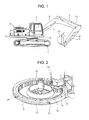
- Construction equipment to which the present invention is applied includes a lower driving structure 1; an upper swing structure 2 mounted on the lower driving structure 1 to be swiveled; a cap 3 and an engine room 4 mounted on the upper swing structure 2; a working device 11 including a boom 6 rotatably fixed to the upper swing structure 2 to be driven by a boom cylinder 6, an arm 8 connected to the boom 6 to be driven by an arm cylinder 7, and a bucket 10 connected to the arm 8 to be driven by a bucket cylinder 9; and a counter weight 12 mounted on the rear of the upper swing structure 2.
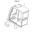
- a grease injection device mounted on construction equipment in the related art includes a swing device 19 including a swing bearing 15 provided with an outer ring 13 fixed to the upper swing structure 2 and an inner ring 14 fixed to a lower frame, and a swing motor 18 that makes the upper swing structure 2 swing against the lower driving structure 1 through a pinion gear 17 tooth-engaged with an inner ring gear 16 of the inner ring 14; a metal pipe 20 fixed to an outer side surface of the outer ring 13; and a grease injection nipple 21 that communicates with the pipe 20 and supplies grease injected from the outside through a grease gun (not illustrated) to a driving portion (i.e. a rolling contact portion between the inner ring and the outer ring) of the swing device.
- a driving portion i.e. a rolling contact portion between the inner ring and the outer ring
- the grease injection nipple 21 and the pipe 20 are exposed to the outside, they may be easily damaged due to collision with external objects in an inferior work environment, and this causes the increase of the cost of the grease injection device.
- the present invention has been made to solve the above-mentioned problems occurring in the prior art while advantages achieved by the prior art are maintained intact.
- An embodiment of the present invention relates to construction equipment having a grease injection device within a cab, which can supply lubricating grease to a swing device driving portion using a grease gun coupled to a grease nipple installed inside the cab.
- An embodiment of the present invention relates to construction equipment having a grease injection device within a cab, which can supply grease without being exposed to weather conditions or a pollution source in the surrounding environment of a work place and regardless of the traveling direction of the construction equipment.
- An embodiment of the present invention relates to construction equipment having a grease injection device within a cab, which does not expose the grease injection device to the outside and thus can prevent the damage of the grease injection device.
- construction equipment which includes a lower driving structure; an upper swing structure including a body frame mounted on the lower driving structure to be swiveled and a bottom plate mounted on the body frame; a swing device that makes the upper swing structure swing against the lower driving structure by an outer ring fixed to the body frame and an inner ring having an inner ring gear formed on an inner side surface of the inner ring, the inner ring gear being tooth-engaged with a pinion gear of a swing motor to make the upper swing structure swing; a cap and an engine room mounted on the upper swing structure; a working device including a boom rotatably fixed to the upper swing structure to be driven by a boom cylinder, an arm connected to the boom to be driven by an arm cylinder, and a bucket connected to the arm to be driven by a bucket cylinder; a counter weight mounted on the rear of the upper swing structure; and a grease injection device including a grease injection nipple fixed to a predetermined position of the bottom plate inside the cab,
- the construction equipment may further include a first connector mounted on a bottom surface of the bottom plate to connect the one end of the pipe that is positioned below the bottom plate to the grease injection nipple so that the pipe communicates with the grease injection nipple, and a second connector mounted on an upper surface of the body frame to connect the other end of the pipe to the paths formed on the body frame and the outer ring, respectively, so that the pipe communicates with the paths.
- the construction equipment having the grease injection device within the cab as constructed above has the following advantages.
- the lubricating grease is supplied to the swing device driving portion using the grease gun coupled to the grease nipple installed inside the cab, and thus the durability of the corresponding components can be increased.
- the operator can inject the grease in a comfortable posture without being exposed to weather conditions or a pollution source in the surrounding environment of a work place and regardless of the traveling direction of the construction equipment, and thus the operator's convenience can be served.
- construction equipment having a grease injection device within a cab includes a lower driving structure 1; an upper swing structure 2 including a body frame 22 mounted on the lower driving structure 1 to be swiveled and a bottom plate 23 mounted on the body frame 22; a swing device 19 that makes the upper swing structure 2 swing against the lower driving structure 1 by an outer ring13 fixed to the body frame 22 and an inner ring 14 having an inner ring gear 16 formed on an inner side surface of the inner ring 14, the inner ring gear 16 being tooth-engaged with a pinion gear 17 of a swing motor 18 to make the upper swing structure 2 swing; a cap 3 and an engine room 4 mounted on the upper swing structure 2; a working device 11 including a boom 6 rotatably fixed to the upper swing structure 2 to be driven by a boom cylinder 5, an arm 8 connected to the boom 6 to be driven by an arm cylinder 7, and a bucket 10 connected to the arm 8 to be driven by a bucket cylinder 9; a counter
- the construction equipment further includes a first connector 29 (e.g. a nut a that fixes the grease injection nipple 25 to the bottom plate 23 and an elbow b that connects the pipe 26 to the grease injection nipple 25) mounted on a bottom surface of the bottom plate 23 to connect the one end of the pipe 26 that is positioned below the bottom plate 23 to the grease injection nipple 25 so that the pipe 26 communicates with the grease injection nipple 25, and a second connector 30 (e.g.
- an elbow b that fixes the pipe 26 to the body frame 22) mounted on an upper surface of the body frame 22 to connect the other end of the pipe 26 to the paths 27 and 28 formed on the body frame 22 and the outer ring 13, respectively, so that the pipe 26 communicates with the paths 27 and 28.
- the unexplained reference numeral 31 is a vibration absorption device mounted on the body frame 22 to prevent impact or the like generated from the lower driving structure 1 from being transferred to the cab 3 through the bottom plate 23, and 32 is a ball bearing inserted into the rolling contact portion between the inner ring 14 and the outer ring 13.
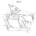
- the grease injection nipple 25 is installed in a predetermined front position within the cab 3 by the first connector 29. That is, the grease injection nipple 25 that is coupled to the bottom plate 23 is fixed by the nut a, and the pipe 26 is connected to the elbow b that is coupled to the grease injection nipple 25.
- the predetermined position of the nipple 25 means a position in which an operator is not interfered with the grease injection nipple 25 when the operator gets in or gets out of the cab 3 or when the operator manipulates a pedal (e.g. a driving pedal or an option device pedal) mounted on the front portion within the cab 3.
- a pedal e.g. a driving pedal or an option device pedal
- the other end of the pipe 26 for supplying the grease injected through the grease injection nipple 25 to the rolling contact portion between the outer ring 13 and the inner ring 14 of the swing device 19 is installed on the body frame 22 by the second connector 30. That is, the pipe 26 is connected to the path 27 formed in the body frame 22 by the elbow b coupled to the body frame 22.
- the operator can supply the grease to the rolling contact portion between the inner ring 14 and the outer ring 13 of the swing device 19 using the grease gun, without seceding from the cab 3. That is, the grease can be injected by coupling the grease gun to the grease injection nipple 25 after opening a lid c of the grease injection nipple 25 installed in front of the bottom plate 23 within the cab 3.
- the grease injected through the grease injection ripple 25 moves along the pipe 26 installed between the bottom plate 23 and the body frame 22, and is supplied to the coupling portion of the ball bearing 32 via the second connector 30 installed on the upper surface of the body frame 22, the path 27 formed on the body frame 22, and the path 28 formed on the outer ring 13 in order.
- the operator since the operator injects the grease into the rolling contact portion between the outer ring 13 and the inner ring 14 of the swing device within the cab 3, the operator can be protected from the inferior work environment where fine particles and so on are generated or various kinds of pollution sources (in the related art, the operator secedes from the cab to inject the grease into the driving portion of the swing device, and thus the operator's body is exposed to the inferior work environment).
- the operator can supply the grease into the driving portion of the swing device 19 within the cab 3 regardless of the traveling direction of the construction equipment and can inject the grease in a comfortable posture, the operator's convenience can be served (in the related art, if the grease injection nipple is positioned in a direction opposite to the traveling direction of the construction equipment, the operator should go down below the upper swing structure to manipulate the grease gun coupled to the grease injection nipple installed on the swing device).
- the pipe 26 and the grease injection nipple 25 for injecting the grease are mounted inside the construction equipment, they are prevented from being damaged while the construction equipment operates in an inferior work environment (in the related art, the grease injection device is exposed to the inferior work environment, and thus may be easily damaged due to collision with external objects while the construction equipment operates).
Landscapes
- Engineering & Computer Science (AREA)
- General Engineering & Computer Science (AREA)
- Mechanical Engineering (AREA)
- Mining & Mineral Resources (AREA)
- Civil Engineering (AREA)
- Structural Engineering (AREA)
- Component Parts Of Construction Machinery (AREA)
Applications Claiming Priority (1)
| Application Number | Priority Date | Filing Date | Title |
|---|---|---|---|
| KR1020090118966A KR20110062289A (ko) | 2009-12-03 | 2009-12-03 | 운전실캡 내부에 그리스 주입장치가 구비된 건설장비 |
Publications (1)
| Publication Number | Publication Date |
|---|---|
| EP2333165A1 true EP2333165A1 (de) | 2011-06-15 |
Family
ID=43617915
Family Applications (1)
| Application Number | Title | Priority Date | Filing Date |
|---|---|---|---|
| EP10193437A Withdrawn EP2333165A1 (de) | 2009-12-03 | 2010-12-02 | Baugerät mit Schmiermittelinjektionsvorrichtung in der Kabine |
Country Status (5)
| Country | Link |
|---|---|
| US (1) | US20110135433A1 (de) |
| EP (1) | EP2333165A1 (de) |
| JP (1) | JP2011117278A (de) |
| KR (1) | KR20110062289A (de) |
| CN (1) | CN102086652A (de) |
Families Citing this family (15)
| Publication number | Priority date | Publication date | Assignee | Title |
|---|---|---|---|---|
| JP5980711B2 (ja) * | 2013-03-29 | 2016-08-31 | 住友重機械工業株式会社 | ショベル |
| CN103741744A (zh) * | 2013-12-25 | 2014-04-23 | 柳州正菱集团有限公司 | 一种挖掘机 |
| CN104652521B (zh) * | 2015-01-27 | 2017-11-07 | 山东临工工程机械有限公司 | 挖掘机回转系统 |
| KR101737551B1 (ko) | 2015-08-28 | 2017-05-18 | (주)마이크로컨텍솔루션 | 테스트 소켓용 컨택트 |
| KR101737550B1 (ko) | 2015-08-28 | 2017-05-18 | (주)마이크로컨텍솔루션 | 콘택트 제조 방법, 콘택트, 및 콘택트를 포함하는 소켓 |
| KR101677709B1 (ko) | 2015-08-31 | 2016-11-21 | (주)마이크로컨텍솔루션 | Ssd 테스트용 젠더 구조 |
| KR101871479B1 (ko) | 2015-11-30 | 2018-06-26 | 소연실 | 완강기 지지대 |
| KR101871480B1 (ko) | 2015-11-30 | 2018-08-02 | 소연실 | 완강기용 기어 및 완강기 |
| KR101659487B1 (ko) | 2015-12-11 | 2016-09-28 | 윤재훈 | 수납 박스 |
| CN106062285B (zh) * | 2016-03-17 | 2021-06-04 | 株式会社小松制作所 | 作业车辆 |
| CN106989262B (zh) * | 2017-05-17 | 2018-08-17 | 广西玉柴重工有限公司 | 一种回转支承齿轮润滑脂槽防水结构 |
| CN109323115A (zh) * | 2018-11-21 | 2019-02-12 | 湖北杜德起重机械有限公司 | 一种起重机吊臂的润滑脂加注机构 |
| KR20230037995A (ko) | 2021-09-10 | 2023-03-17 | (주)마이크로컨텍솔루션 | Ssd 테스트용 젠더 |
| CN114622616B (zh) * | 2022-05-16 | 2022-07-19 | 徐州东方传动机械股份有限公司 | 一种电动防爆挖掘机的回转装置 |
| CN116025022B (zh) * | 2022-12-27 | 2023-09-26 | 金诚信(湖北)智能装备有限公司 | 一种铲运机 |
Citations (8)
| Publication number | Priority date | Publication date | Assignee | Title |
|---|---|---|---|---|
| US3990539A (en) * | 1970-08-05 | 1976-11-09 | Caterpillar Tractor Co. | Lubrication means for swing gear drive |
| JPS5242501U (de) * | 1975-09-19 | 1977-03-26 | ||
| JPS52166301U (de) * | 1976-06-10 | 1977-12-16 | ||
| US4244447A (en) * | 1979-01-08 | 1981-01-13 | Northwest Engineering Company | Mobile power crane-excavator with open gear greasing |
| JPH0269160U (de) * | 1988-11-16 | 1990-05-25 | ||
| JP2000110197A (ja) * | 1998-10-02 | 2000-04-18 | Shin Caterpillar Mitsubishi Ltd | 作業用車両の給脂構造 |
| JP2000205283A (ja) * | 1999-01-11 | 2000-07-25 | Shin Caterpillar Mitsubishi Ltd | 旋回軸受の給脂構造 |
| KR20090008528A (ko) * | 2007-07-18 | 2009-01-22 | 두산인프라코어 주식회사 | 선회식 작업차량의 선회베어링을 위한 그리스 급지구조 |
Family Cites Families (7)
| Publication number | Priority date | Publication date | Assignee | Title |
|---|---|---|---|---|
| JPS5187656A (ja) * | 1975-01-23 | 1976-07-31 | Caterpillar Tractor Co | Hagurumakudokiko |
| JPS528784U (de) * | 1975-07-08 | 1977-01-21 | ||
| JPS6212157Y2 (de) * | 1979-06-16 | 1987-03-26 | ||
| JPH0258059U (de) * | 1988-10-18 | 1990-04-26 | ||
| JP2559229Y2 (ja) * | 1992-09-11 | 1998-01-14 | 新キャタピラー三菱株式会社 | 作業用走行車における給脂構造 |
| JP4740088B2 (ja) * | 2006-10-23 | 2011-08-03 | 日立建機株式会社 | 建設機械 |
| CN101230947A (zh) * | 2007-04-26 | 2008-07-30 | 张立民 | 衡润自动黄油机 |
-
2009
- 2009-12-03 KR KR1020090118966A patent/KR20110062289A/ko not_active Application Discontinuation
-
2010
- 2010-12-01 CN CN2010105676703A patent/CN102086652A/zh active Pending
- 2010-12-02 US US12/958,757 patent/US20110135433A1/en not_active Abandoned
- 2010-12-02 EP EP10193437A patent/EP2333165A1/de not_active Withdrawn
- 2010-12-03 JP JP2010269915A patent/JP2011117278A/ja active Pending
Patent Citations (8)
| Publication number | Priority date | Publication date | Assignee | Title |
|---|---|---|---|---|
| US3990539A (en) * | 1970-08-05 | 1976-11-09 | Caterpillar Tractor Co. | Lubrication means for swing gear drive |
| JPS5242501U (de) * | 1975-09-19 | 1977-03-26 | ||
| JPS52166301U (de) * | 1976-06-10 | 1977-12-16 | ||
| US4244447A (en) * | 1979-01-08 | 1981-01-13 | Northwest Engineering Company | Mobile power crane-excavator with open gear greasing |
| JPH0269160U (de) * | 1988-11-16 | 1990-05-25 | ||
| JP2000110197A (ja) * | 1998-10-02 | 2000-04-18 | Shin Caterpillar Mitsubishi Ltd | 作業用車両の給脂構造 |
| JP2000205283A (ja) * | 1999-01-11 | 2000-07-25 | Shin Caterpillar Mitsubishi Ltd | 旋回軸受の給脂構造 |
| KR20090008528A (ko) * | 2007-07-18 | 2009-01-22 | 두산인프라코어 주식회사 | 선회식 작업차량의 선회베어링을 위한 그리스 급지구조 |
Also Published As
| Publication number | Publication date |
|---|---|
| CN102086652A (zh) | 2011-06-08 |
| KR20110062289A (ko) | 2011-06-10 |
| JP2011117278A (ja) | 2011-06-16 |
| US20110135433A1 (en) | 2011-06-09 |
Similar Documents
| Publication | Publication Date | Title |
|---|---|---|
| EP2333165A1 (de) | Baugerät mit Schmiermittelinjektionsvorrichtung in der Kabine | |
| CN106917430B (zh) | 自推进的工作机器 | |
| US9554514B2 (en) | Rotary cutter implement with ball joint connection to a power machine | |
| US8851826B2 (en) | Bucket and work vehicle | |
| US6772544B2 (en) | Wheeled work vehicle | |
| US9027986B2 (en) | Wiper device, open/close guard with wiper device, and cab for construction machine | |
| CN101023223A (zh) | 具有提升臂行程限制器的工作机械 | |
| US20140003901A1 (en) | Hydraulic excavator | |
| JP3829071B2 (ja) | 建設機械 | |
| US20170175357A1 (en) | Work vehicle | |
| JP4867651B2 (ja) | 建設機械のキャビンヘッドガード装置 | |
| EP1333143A2 (de) | Öffnungs- und Schliessvorrichtung für Kraftfahrzeugtür | |
| CN103485376A (zh) | 工程机械 | |
| JP2006205922A (ja) | 車両搭載型作業機 | |
| JPS6212157Y2 (de) | ||
| JP2009227213A (ja) | 車両および作業機械 | |
| GB2393708B (en) | Excavating and loading machine | |
| CN215663058U (zh) | 驾驶室及工程机械 | |
| CN2868808Y (zh) | 驾驶室前面罩翻转保护装置 | |
| JPH04114Y2 (de) | ||
| JP4883626B2 (ja) | 車両 | |
| JPH10191706A (ja) | 畦塗機 | |
| CN100999229B (zh) | 驾驶室前面罩翻转保护装置 | |
| CN208763105U (zh) | 一种内嵌式挖掘机扶手架 | |
| JPS6326447Y2 (de) |
Legal Events
| Date | Code | Title | Description |
|---|---|---|---|
| PUAI | Public reference made under article 153(3) epc to a published international application that has entered the european phase |
Free format text: ORIGINAL CODE: 0009012 |
|
| AK | Designated contracting states |
Kind code of ref document: A1 Designated state(s): AL AT BE BG CH CY CZ DE DK EE ES FI FR GB GR HR HU IE IS IT LI LT LU LV MC MK MT NL NO PL PT RO RS SE SI SK SM TR |
|
| AX | Request for extension of the european patent |
Extension state: BA ME |
|
| 17P | Request for examination filed |
Effective date: 20111215 |
|
| 17Q | First examination report despatched |
Effective date: 20120606 |
|
| STAA | Information on the status of an ep patent application or granted ep patent |
Free format text: STATUS: THE APPLICATION IS DEEMED TO BE WITHDRAWN |
|
| 18D | Application deemed to be withdrawn |
Effective date: 20121017 |