EP2332601A1 - Syringe - Google Patents
Syringe Download PDFInfo
- Publication number
- EP2332601A1 EP2332601A1 EP09809860A EP09809860A EP2332601A1 EP 2332601 A1 EP2332601 A1 EP 2332601A1 EP 09809860 A EP09809860 A EP 09809860A EP 09809860 A EP09809860 A EP 09809860A EP 2332601 A1 EP2332601 A1 EP 2332601A1
- Authority
- EP
- European Patent Office
- Prior art keywords
- distal end
- aperture
- end nozzle
- syringe
- range
- Prior art date
- Legal status (The legal status is an assumption and is not a legal conclusion. Google has not performed a legal analysis and makes no representation as to the accuracy of the status listed.)
- Withdrawn
Links
Images


Classifications
-
- A—HUMAN NECESSITIES
- A61—MEDICAL OR VETERINARY SCIENCE; HYGIENE
- A61M—DEVICES FOR INTRODUCING MEDIA INTO, OR ONTO, THE BODY; DEVICES FOR TRANSDUCING BODY MEDIA OR FOR TAKING MEDIA FROM THE BODY; DEVICES FOR PRODUCING OR ENDING SLEEP OR STUPOR
- A61M5/00—Devices for bringing media into the body in a subcutaneous, intra-vascular or intramuscular way; Accessories therefor, e.g. filling or cleaning devices, arm-rests
- A61M5/178—Syringes
- A61M5/28—Syringe ampoules or carpules, i.e. ampoules or carpules provided with a needle
-
- A—HUMAN NECESSITIES
- A61—MEDICAL OR VETERINARY SCIENCE; HYGIENE
- A61M—DEVICES FOR INTRODUCING MEDIA INTO, OR ONTO, THE BODY; DEVICES FOR TRANSDUCING BODY MEDIA OR FOR TAKING MEDIA FROM THE BODY; DEVICES FOR PRODUCING OR ENDING SLEEP OR STUPOR
- A61M5/00—Devices for bringing media into the body in a subcutaneous, intra-vascular or intramuscular way; Accessories therefor, e.g. filling or cleaning devices, arm-rests
- A61M5/178—Syringes
- A61M5/24—Ampoule syringes, i.e. syringes with needle for use in combination with replaceable ampoules or carpules, e.g. automatic
-
- A—HUMAN NECESSITIES
- A61—MEDICAL OR VETERINARY SCIENCE; HYGIENE
- A61M—DEVICES FOR INTRODUCING MEDIA INTO, OR ONTO, THE BODY; DEVICES FOR TRANSDUCING BODY MEDIA OR FOR TAKING MEDIA FROM THE BODY; DEVICES FOR PRODUCING OR ENDING SLEEP OR STUPOR
- A61M5/00—Devices for bringing media into the body in a subcutaneous, intra-vascular or intramuscular way; Accessories therefor, e.g. filling or cleaning devices, arm-rests
- A61M5/178—Syringes
- A61M5/31—Details
- A61M2005/3103—Leak prevention means for distal end of syringes, i.e. syringe end for mounting a needle
- A61M2005/3104—Caps for syringes without needle
-
- A—HUMAN NECESSITIES
- A61—MEDICAL OR VETERINARY SCIENCE; HYGIENE
- A61M—DEVICES FOR INTRODUCING MEDIA INTO, OR ONTO, THE BODY; DEVICES FOR TRANSDUCING BODY MEDIA OR FOR TAKING MEDIA FROM THE BODY; DEVICES FOR PRODUCING OR ENDING SLEEP OR STUPOR
- A61M5/00—Devices for bringing media into the body in a subcutaneous, intra-vascular or intramuscular way; Accessories therefor, e.g. filling or cleaning devices, arm-rests
- A61M5/178—Syringes
- A61M5/31—Details
- A61M5/3129—Syringe barrels
- A61M5/3137—Specially designed finger grip means, e.g. for easy manipulation of the syringe rod
- A61M2005/3139—Finger grips not integrally formed with the syringe barrel, e.g. using adapter with finger grips
Definitions
- the present invention relates to syringes and, more particularly, relates to syringes suitable for use as pre-filled syringes filled beforehand with medicinal liquid.
- pre-filled syringes they are shipped in such a manner that their caps are mounted respectively on their distal end nozzles to thereby place the medicinal liquid filled inside is placed in a hermetically sealed state.
- this invention relates to a syringe capable of getting rid of the possibility of the occurrence of "link-thread" (i.e., the formation of a viscous thread) from the distal end nozzle at the time the syringe is actually used after shipment in the form of a pre-filled syringe.
- link-thread i.e., the formation of a viscous thread
- the medicinal liquid filed inside is placed in a hermetically sealed state between the gasket engaged in through the proximal end opening of the pre-filled syringe and the cap mounted onto the distal end nozzle. Then, with the filled medicinal liquid in such a hermetically sealed state, the pre-filled syringe is subjected to a sterilization treatment and, thereafter, is shipped and provided to a medical institution and so on.
- Patent Literature I discloses a pre-filled syringe of the following type.
- this disclosure shows that there is formed a luer lock so as to encircle a distal end nozzle of the pre-filled syringe, that a cap is mounted onto the distal end nozzle so as to provide also covering of the outer peripheral surface of the luer lock, and that there is formed in the outer peripheral surface of the luer lock a deaeration groove extending in the direction from the distal end to the proximal end.
- the deaeration groove prevents the air, enclosed in an empty space between the distal end nozzle and the luer lock, from expanding upon receipt of heat or the like in association with the sterilization treatment. This prevents the cap from being drawn off.
- the inner peripheral surface 105 of the cap 103 moves in the pull-off direction while it remains in close contact with the outer peripheral surface 104 of the distal end nozzle 101 and, as a result, the gap space K defined between the inner back surface 107 of the cap 103 and the side of the distal end opening 102 of the distal end nozzle 102 expands while it remains hermetically sealed. This causes the gap space K to enter into a semi-vacuum state (reduced pressure state).
- the result is that the medicinal liquid scatters immediately after the "link-thread” is broken. This will cause inconveniences. That is, the scattered medicinal liquid may adhere to the clothes and the hands of a healthcare practitioner who is dealing with the pre-filled syringe.
- the liquid bead Q1 (see Figure (b)) is formed by surface tension at the distal end opening 102 of the distal end nozzle 101 after the "link-thread” is broken, so that the liquid bead Q1 is in an exposed state to the outside space.
- an object of the present invention is to provide a syringe capable of avoiding the occurrence of "link-thread” even if the medicinal liquid filled has a high viscosity and therefore capable of avoiding the occurrence of inconvenience due to the occurrence of "link-thread".
- the present invention is intended for a syringe which comprises: a synthetic resin barrel which is provided with a distal end nozzle, the distal end nozzle projecting and opening on the side of a distal end of said barrel; a cap which, when mounted onto the distal end nozzle, hermetically closes a distal end opening of the distal end nozzle; and a gasket which, when engaged in through a proximal end opening of the barrel, hermetically closes the side of a proximal end of the barrel.
- this syringe has the following characteristics.
- the aperture diameter of an inner aperture of the distal end nozzle at least, at the position of the distal end opening of the distal end nozzle is set so as to fall within the aperture diameter range of substantially from 0.1 to 1.0 mm. More preferably, the aperture diameter of the inner aperture is set so as to fall within the range of from 0.5 to 1.0 mm.
- the diameter of the filled medicinal liquid to be sucked in is extremely small, as corresponds to the aperture diameter of the distal end opening, since the distal end opening of the distal end nozzle is formed so as to have a small aperture diameter falling within the range of from 0.1 to 1.0 mm as described above.
- a medicinal liquid whose viscosity falls within the range of from 1000 to 60000 mPa ⁇ s
- hyaluronic acid preparations may be used.
- the cap includes a tubular part for engagement onto the distal end nozzle.
- the inner peripheral surface is extended from the opening end on one side of the tubular part to the inner back surface on the other side so that the tubular part is closed off at one end.
- the length to be sealed thus (seal length) can be set so as to fall within the range of substantially from 2.0 to 6 mm. More preferably, the seal length can be set so as to fall within the range of substantially from 3.0 to 6.0 mm.
- the inner aperture of the distal end nozzle is formed so as to have an aperture diameter that falls within the aforesaid aperture diameter range and, in the case of the latter partial diameter aperture formation in the inner aperture, the inner aperture of the distal end nozzle is reduced in diameter over the range of length from 0.3 to 3.0 mm from the position of the distal end opening to the proximal end side whereby the inner aperture of the distal end nozzle is formed so as to have an aperture diameter falling within the aforesaid aperture diameter range.
- the range of the reduction in diameter is set less than 0.3 mm, this may cause a tendency of deficiency in strength against the pressure at the time the medicinal liquid filled in the barrel is pushed out.
- the range of the reduction in diameter is set longer than 3.0 mm, this results in formation of a lengthy thick portion with the outer peripheral surface of the distal end nozzle constituting a male luer taper, thereby causing the possibility of the occurrence of sink at the time of synthetic resin molding.
- the outer peripheral surface of the distal end nozzle is formed into a predetermined male luer taper by setting the range of the reduction in diameter so as to fall within the aforesaid length range and, at the same time, it becomes possible to definitely form the inner aperture of the distal end nozzle so that it has an aperture diameter capable of preventing the occurrence of "link-thread" without causing any inconvenience such as the occurrence of sink due to synthetic resin molding. That is, while realizing the requisition for the male luer taper with respect to the outer peripheral surface of the distal end nozzle, it additionally becomes possible to realize the aforesaid aperture diameter range while avoiding the formation of an excessively thick portion and the occurrence of inconvenience due to synthetic resin molding.
- the diameter of the filled medicinal liquid to which suction is applied can be made extremely small, as corresponds to the aperture diameter of the distal end opening, by forming the distal end opening of the distal end nozzle so as to have a small aperture diameter falling within the range of from 0.1 to 1.0 mm.
- the medicinal liquid filled is a high viscosity medicinal liquid
- the medicinal liquid adhered to the cap is torn apart instantly as the cap is pulled off to a further extent, thereby making it possible to avoid the occurrence of "link-thread". That is, even in the case where a medicinal liquid of high viscosity is filled to form a pre-filled syringe, it is possible to avoid the possibility of the occurrence of "link-thread" at the point of use, i.e., when the cap is removed, thereby making it possible to prevent the occurrence of inconvenience due to the occurrence of "link-thread".
- the inner aperture of the distal end nozzle By forming a part or all of the inner aperture of the distal end nozzle to have an aperture diameter falling within the aforesaid aperture diameter range, it becomes possible to definitely manufacture a syringe according to the present invention. Furthermore, by forming the inner aperture of the distal end nozzle to have an aperture diameter falling within the aforesaid aperture diameter range over the range of length (from 0.3 to 3.0 mm) from the position of the distal end opening to the proximal end side, it becomes possible to prevent the formation of an excessively thick portion while realizing the requisition for a male luer taper with respect to the outer peripheral surface of the distal end nozzle. This makes it possible to definitely realize the aforesaid aperture diameter range while preventing the occurrence of inconvenience due to synthetic resin molding whereby the avoidance of "link-thread" by the present invention can be accomplished.
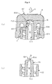
- FIGS 1-3 illustrate a syringe according to an embodiment of the present invention, in which figures a barrel which is a syringe tube of the syringe 1 is denoted by reference numeral 2, a gasket is denoted by reference numeral 3, a plunger rod is denoted by reference numeral 4, a finger grip is denoted by reference numeral 5 and a cap for sealing is denoted by reference numeral 6.
- the barrel 2 is made of transparent plastic (synthetic resin). Formed on the side of a distal end of the barrel 2 are a distal end nozzle 21 and a luer lock adapter 22 (see Figure 2 and Figure 3 for both of these parts). On the other hand, formed on the side of a proximal end of the barrel 2 are a proximal end opening 23 (see Figure 3 ) and a proximal end flange 24 projecting on the side of an outer peripheral surface of the proximal end opening 23. And, it is configured that the cap 6 is detachably mounted onto the distal end nozzle 21 and the luer lock adapter 22 and that the finger grip 5 is detachably mounted to the proximal end flange 24 from the lateral direction.
- the distal end side of the barrel 2 is formed in a double tube structure by the distal end nozzle 21 and the luer lock adapter 22. And the cap 6 is mounted, in a close contact manner, onto the distal end nozzle 21 which is in fluid communication with the inside of the barrel 2, thereby liquid tightly sealing off the distal end opening of the barrel 2 while providing covering of the outer peripheral surface of the luer lock adapter 22. Details of the structure of the distal end side of the barrel 2 will be hereinafter described.
- a plurality of ribs 31, 31, ... having a slightly expanded diameter are formed integrally with and on the outer peripheral surface of the gasket 3.
- Each rib 31 closely and liquid tightly contacts with the inner peripheral surface of the barrel 2, thereby blocking leakage of the medicinal liquid held in the barrel 2 on the distal end side ahead of the gasket 3.
- a concave part 32 (see Figure 3 ) which opens to the proximal end side of the barrel 2 and which has in its inner peripheral surface a thread groove, and a thread part 42 (see Figure 2 and Figure 3 ) of the plunger rod 4 is screwed in the concave part 32 so that the gasket 3 is integrally coupled to the distal end of the plunger rod 4.
- a plunger With the plunger rod 4 and the gasket 3 made integral with each other, there is now constituted a plunger.
- a medicinal liquid chamber 25 (see Figure 3 ) for holding medicinal liquid is defined, by partitioning, in the inside of the barrel 2 ahead of the gasket 3.
- the plunger rod 4 includes a rod main body 41 which is shaped like a cross in transverse cross section, a thread part 42 which projects from the distal end position of the rod main body 41 in the direction of the distal end of the barrel 2 and an operation part 43 which extends circumferentially from the proximal end position of the rod main body 41 and, in addition to these parts, the plunger rod 4 further includes a disc part 44 and a disc part 45 at the distal end position of the rod main body 41 and at at the intermediate position of the rod main body 41 at a given distance away from the distal end position in the direction of the proximal end side, respectively.
- the disc part 44 at the distal end position is given an outside diameter capable of abutting and covering almost the entire backside of the gasket 3.
- the disc part 45 is given an outside diameter which is set as follows. That is, the outside diameter of the disc part 45 is smaller, just by such a slight extent that it becomes minimum in the range that allows the disc part 45 to advancingly and retreatingly move within the barrel 2, than the inside diameter of the barrel 2. But the outside diameter of the disk part 45 is larger, by a predetermined amount, than the outside diameter of a virtual circular arc formed by connecting together outer peripheral end edges of the cross-shaped body constituting the rod main body 41.
- This part that projects so as to have a larger diameter than the outside diameter of the rod main body 41 abuts and stops against an aperture edge 521 of the finger grip 521 (hereinafter described), thereby preventing a further movement in the pull-off direction. This prevents the plunger rod 4 from being pulled off of the barrel 2.
- a concave part 451 (see Figure 1 or Figure 2 ) is formed by concavely cutting away a part of the outer peripheral edge of the disc part 45 into a concave shape, and gas for sterilization is circulated, through the concave part 451, between the proximal end side and the distal end side in the barrel 2. That is, the concave part 451 establishes mutual fluid communication between a semi-hennetically closed space sandwiched between both the disc parts 44, 45 in the barrel 2 and the inside of the barrel 2 in fluid communication through the proximal end opening 23 to the outside, thereby making gas for sterilization (for example, hydrogen peroxide gas) circulatable.
- gas for sterilization for example, hydrogen peroxide gas
- the finger grip 5 has a grip main body 51 from which grip parts 511, 511 stretch out to the right-hand side and to the left-hand sides, respectively so as to project bilaterally across the proximal end flange 24 of the barrel-2, thereby forming a finger hook portion for grasping at the time of performing a syringe operation with the syringe 1.
- the grip main body 51 is of the type that includes an aperture part 52 into which the barrel 2 is inserted passing completely through the central position of the grip main body 51 and a concave groove part 53 which is in fluid communication with the aperture part 52 and which is able to accommodate the proximal end flange 24.
- aperture edge 521 which is the aperture edge of the aperture part 52 and which is situated on the proximal end side across the concave groove part 53, the aperture edge 512 being configured such that it has an inside diameter which is equal to the outside diameter of the rod main body 41 of the plunger rod 4 and which is set to be smaller than the outside diameter of the disc part 45 and there is an aperture edge 522 on the distal end side which is configured such that it has a diameter approximately equal to the outside diameter of the barrel 2.
- the finger grip 5 becomes immobile and the proximal end opening 23 is narrowed by the aperture edge 521 on the proximal end side.
- the distal end nozzle 21 constitutes an inner tubular portion of the double tube structure.
- the distal end nozzle 21 is configured as follows. That is, the distal end nozzle 21 extends along the central axis X up to a certain position so that it projects more than the luer lock adapter 22 of the barrel 2 by a given length in the direction of the distal end side, and its outer peripheral surface 241 constitutes a male luer taper part. And, it is set such that the aperture diameter, d , of the distal end nozzle 21 at the position of the distal end opening 211 (see Figure 4 ) has a predetermined small diameter.
- the aperture diameter d is formed such that it has a small diameter dimension selected from among the following aperture diameter ranges: Practically, an aperture diameter range 0.1-1.0 mm; preferably, either an aperture diameter range 0.4-1.0 mm or an aperture diameter range 0.5-1.0 mm; more preferably, either an aperture diameter range 0.4-0.7 mm or an aperture diameter range 0.5-0.7 mm.
- an aperture diameter range 0.1-1.0 mm preferably, either an aperture diameter range 0.4-1.0 mm or an aperture diameter range 0.5-1.0 mm; more preferably, either an aperture diameter range 0.4-0.7 mm or an aperture diameter range 0.5-0.7 mm.
- the threshold limit value for the small diameter side is subjected to the restriction mainly from the manufactural viewpoint, whereas the threshold limit value for the large diameter side is subjected to the restriction mainly from the functional viewpoint.
- the distal end nozzle 21 is formed together with the barrel 2 by means of synthetic resin molding, this will accompany difficulties with stably and precisely forming the aperture diameter d at less than 0.1 mm and, in addition, this will further accompany difficulties with stably, precisely and mass-productively forming the aperture diameter d at even less than either 0.4 or 0.5 mm.
- the aperture diameter range 0.5-0.7 mm is an aperture diameter range of from 0.5 mm to 0.7 mm (i.e., an aperture diameter range of from not less than 0.5 mm to not more than 0.7 mm) and, in that regard, what are meant by "not less than” and “not more than” are practical ranges.
- this representation when represented as “not less than 5 mm”, this representation includes also 0.49 mm and so on, and when represented as “not more than 7 mm”, this representation includes also 0.71 mm and so on. Also in the following description, the similar range representation has the similar definition.
- the inner aperture of the distal end nozzle 21 is formed such that it has the aperture diameter d throughout, or the entire inner aperture of the distal end nozzle 21 is formed into a taper shape in parallel with the male luer taper part so as to have the aperture diameter d at the position of the distal end opening 211, or the inner aperture of the distal end nozzle 21 is partially reduced so as to have the aperture diameter d, or preferably a distal end side part of the inner aperture 212 is formed (in a predetermined range) so as to have the aperture diameter d as exemplarily shown in the figure.
- the inner aperture 212 When formed in the predetermined range on the distal end side (as exemplarily shown in the figure), the inner aperture 212 is reduced in diameter by forming a bulge part 213 which is situated on the distal end side of the inner aperture 212 and which bulges inwardly over a predetermined range of length e from the distal end opening 21 whereby the inside diameter of the bulge part 213 becomes equal to the the aperture diameter d .
- the length range e it suffices to set a length range of, substantially, from 0.3 mm to 3.0 mm from the position of the distal end opening 211 on the distal end side of the inner aperture 212.
- the length range e is too short, this may cause the possibility that the bulge part 213 yields to the pressure exerted when the filled medicinal liquid is pushed out and itself undergoes folding breakage.
- the length range e is, conversely, too long, this causes the thick portion to become bulky, as corresponds to the extension in the length range e and, as a result, sink is prone to take place. Therefore, the aforesaid length range is preferable.
- the luer lock adapter 22 constitutes an outer tubular portion which encircles the outer peripheral side of the distal end nozzle 21.
- the luer lock adapter 22 is formed on the outer peripheral side of the distal end nozzle 21 and in a coaxial manner, relative to the central axis X, with the distal end nozzle 21 across an annular space 26 into which the female luer taper part, such as a syringe needle or the like, is placed.
- each convex part 222 prevents the inner peripheral surface of an outer tubular cover part 62 of the cap 6 from being placed in close contact with an outer peripheral surface 224 of the luer lock adapter 22, as will be hereinafter described.
- the cap 6 is of the type that is formed in one piece of a synthetic resin such as rubber or other like material.
- the cap 6 has an inner and outer double tubular structure that is opened to the proximal end side wherein the inner and outer double tubular structure of the cap 6 is formed by an outer tubular cover part 62 which extends from the periphery of a top wall part 61 on the distal end side to the proximal end side, and a cap seal part 63 which extends, on the inner peripheral side of the outer tubular cover part 62, from the inner surface of the top wall part 61 to the proximal end side so as to be arranged coaxially with the outer tubular cover part 62.
- the cap seal part 63 is formed so as to include an inner peripheral surface 631 and an opening end surface 632.
- the inner peripheral surface 631 has a shape capable of close contact, when the cap 6 is mounted onto the distal end nozzle 21, with an outer peripheral surface 214 of the distal end nozzle 21 while being elastically compressed by a given amount in the radial direction.
- the opening end surface 632 extends for a given seal length s from the distal end opening 211 of the distal end nozzle 21 to the proximal end side and is positioned.
- the seal length s is set by selection from among the dimensions of a range of from 2.0 to 6.0 mm, preferably either from among the dimensions of a range of from 3.0 to 6.0 mm or from among the dimensions of a range of from 3.0 to 5.0 mm.
- the seal length s is assigned the aforesaid ranges, the reason for which is that if the seal length s is too short then it becomes impossible to aim at maintaining and securing the sealability and, conversely, if the seal length s is too long then it becomes impossible to effectively avoid the occurrence of "link-thread" in relation to the viscosity of the filled medicinal liquid even when the aperture diameter d of the distal end nozzle 21 is set at a dimension on the practical minimum side.
- the seal length s is set much shorter than that of conventional caps of the type that is brought into close contact with the outer peripheral surface 214 of the distal end nozzle 21 for hermetical sealing of the distal end opening 211 whereby the cap seal part 63 is prevented from close contact with most of the distal end nozzle 21 on the proximal end side.
- the length of projection of the cap seal part 63 from the top wall part 61 to the proximal end side along the central axis X is set much shorter than the length of projection of the distal end nozzle 21 to the distal end side.
- the setting of geometry is made for an inner back surface 633 of the seal cap part 63 and a distal end surface 215 of the distal end nozzle 21 to be placed in close contact with each other, but these surfaces may be placed in such a state that they are separated a very small dimension.
- the reason for this is that the sealing-off of the distal end opening 211 is secured by close contact of the amount of the seal length s of the inner peripheral surface 631 of the seal cap part 63 to the outer peripheral surface 214 of the distal end nozzle 21.
- the cap seal part 63 is formed such that, in the aforesaid mounted state in which the cap 6 is mounted onto the distal end nozzle 21 and the seal cap part 63 is placed within the annular space 26, there is left, between the outer peripheral surface 634 and the inner peripheral surface of the luer lock adapter 22, a gap.
- the radial width of the annular groove 64 between the seal cap part 63 and the outer tubular cover 62 is set greater than the radial width of the luer lock adapter 22 including the thread 221 and, in addition, the dimensions and the shape thereof are set so that, in the aforesaid mounted state, gaps are formed, respectively, between the groove bottom surface of the annular groove 64 and the distal end surface 223 of the luer lock adapter 22 and between the inner peripheral surface 621 of the outer tubular cover part 62 and the outer peripheral surface 224 of the luer lock adapter 22, thereby allowing the annular space 26 to be in fluid communication with the outside even in the aforesaid mounted state.
- the maintaining of this fluid communication is definitely ensured by the following means.
- an arrow-shaped part 67 Formed integrally with and on the distal end surface of the top wall part 61 is an arrow-shaped part 67 in the form of a convex (see Figure 2 ).
- the arrow-shaped part 67 is provided for the purpose of guiding and showing a user that the cap 6 can be removed easily by rotating it in the arrow direction.
- the flow of process up to the shipping includes an individual sterilization step, a medicinal liquid filling/assembly step, a packaging step and a final sterilization step which steps are performed in that order.
- the individual sterilization step is a step in which component parts, such as the barrel 2, the gasket 3, the plunger rod 4, the finger grip 5 and the cap 6, are individually subjected to a sterilizing treatment such as, for example, a high-temperature steam sterilizing treatment.
- the medicinal liquid chamber 25 is filled with a medicinal liquid by means of, for example, a vacuum filling method. Thereafter, the plunger rod 4 is inserted so that its distal end is coupled to the gasket 3. Then, the finger grip 5 is mounted to the flange 24 to form a pre-filled syringe (see the state shown in Figure 1 ).
- the packaging step the pre-filled syringe after having being filled with the medicinal liquid is placed in a package body (such as a blister container, a package bag having a gas permeable part, or the like) which is then hermetically sealed. With the syringe packed in the package body, the final sterilization step is carried out using hydrogen peroxide gas or the like.
- the present embodiment is intended for using, as the medicinal liquid (pharmaceutical preparation) to be filled in the medicinal liquid filling/assembly step, medicinal liquids having a high viscosity of from 1000 to 60000 mPa ⁇ s.
- a high viscosity medicinal liquid includes hyaluronic acid preparations.
- the hyaluronic acid preparations there is a solution prepared by dissolving either hyaluronate sodium derived by microbial fermentation or hyaluronate sodium derived by extraction from chicken comb, cow's eye vitreous body or umbilical cord, or the like, into injection water or injection solution liquid such as normal saline solution.
- the diameter of the filled medicinal liquid M sucked from the distal end opening 211 is equal to or smaller than the aperture diameter d of the distal end opening 211 (see Figure 4 ) and, therefore, disconnection tends to take place and, in addition, the amount of medicinal liquid itself drawn by suction decreases in proportion to the square of the rate of diameter reduction of the aperture diameter, in comparison with conventionally used ones.
- the seal length s of the seal cap part 63 is shorter than conventionally used ones and, therefore, the aforesaid vacuum pressure reduction tendency is instantly broken by movement of the cap 6 in the pull-off direction, thereby causing suction power against the filled medicinal liquid M to disappear.
- the size of a liquid bead Q (see Figure 6(b) ) left at the distal end opening 211 of the distal end nozzle 21 when the cap 6 is completely removed can also be reduced to a large extent with the reduction in diameter of the distal end opening 211. That is, it also becomes possible to reduce the existence of the liquid bead Q to be exposed to the outside space in proportion to the square of the rate of aperture diameter reduction, in comparison with to the liquid bead Q1 of Figure 9(b) .
- this removing operation of the cap 6 can be carried out easily by removing it from the barrel 2 while rotating it in the direction indicated by the arrow of the arrow-shaped part 67 and, besides, it becomes possible to slow down the appearance of a tendency of vacuum pressure reduction by preventing the gap space K from rapid expansion whereby the degree of suction against the filled medicinal liquid M can also be reduced. This make a contribution to the avoidance of the occurrence of "link-thread".
- the present invention is not limited to the aforesaid embodiment and, therefore, includes other various embodiments. That is, the syringe shown in the aforesaid embodiment has the luer lock adapter 22 at the distal end side of the barrel 2 and the outer tubular cover part 62 for covering the luer lock adapter 22. This is however should not be considered restrictive in any way. It is possible to form a barrel of the type without the luer lock adapter 22 and it is possible to form a cap of the type without the outer tubular cover part 62. This is because the main idea of the present invention is the configuration of the distal end nozzle 21 and the configuration of the seal cap part 63 which are shown in the aforesaid embodiment.
- Syringes in the basic form of the aforesaid embodiment were filled with high viscosity medicinal liquid and were used as testing pre-filled syringes.
- testing was conducted in order to check whether there occurred "link-thread" when the cap was removed.
- the barrel 2 seven different types were prepared having their respective aperture diameters D (namely, 1.5 mm, 1.3 mm, 1.0 mm, 0.7 mm, 0.6 mm, 0.5 mm and 0.4 mm) over the range of length e of the inner aperture's 212 distal end side from the distal end opening 211(see Figure 4 ).
- the cap 6 five different types were prepared having their respective seal part lengths S (namely, 8.0 mm, 6.0 mm, 4.5 mm, 3.0 mm and 2.0 mm).
- Each test piece was filled with hyaluronic acid preparation (as a medicinal liquid to be filled) of from 30000 to 500000 mPa ⁇ s (measured by a type-B viscometer). These 350 (35 x 10) test pieces were used for testing and, more specifically, 10 test pieces per each of the 35 combinations of the aperture diameter D and the seal length S were subjected to pull-off testing.
- the representation of D as the aperture diameter and the representation of S as the seal length indicate, respectively, the aperture diameter and the seal length in the present testing and, on the other hand, the representation of d as the aperture diameter and the representation of s as the seal length indicate, respectively, the aperture diameter and the seal length in the foregoing embodiment.
- the pull-off (removal) testing was carried out in the following way.
- Each pre-filled syringe was fixed to a tension-compression testing device, with its cap positioned downside. Then, the cap was withdrawn downwardly by means of a special jig at a speed of 1000 mm/min.
- the existence or nonexistent of the occurrence of "link-thread” was checked with eyes. Visual confirmation of the occurrence of "link-thread” was classified as the presence of "link-thread”. On the other hand, when the occurrence of "link-thread” was not visually confirmed, this was classified as the absence of "link-thread".
- the arrangement that the cap was positioned downside was made on the assumption that "link-thread" was most likely to take place in such positioning, in other words, on the assumption of the worst possible use status.
- Figure 7 in the form of a table summarizes the results of the testing.
- n is indicative of the number of syringes that had undergone "link-thread”
- N is indicative of the number of syringes which were tested under the same conditions (10 syringes in the present testing example)
- n / N is indicative of the ratio of the number of syringes that had undergone "link-thread” against all of the 10 syringes.
- the notation of 1/10 shows that, of all the 10 syringes tested, the number of syringes that had undergone "link-thread" is one, and that the remaining 9 syringes were free from "link-thread".
- the seal length s to be combined therewith is required to fall within the range of substantially not more than 3.0 mm nor less than 2.0 mm in order that the occurrence of "link-thread" is avoided.
- the present invention provides a syringe which is distributed and provided as a pre-filled syringe in the filed of medicine or other like field.
Landscapes
- Health & Medical Sciences (AREA)
- Vascular Medicine (AREA)
- Engineering & Computer Science (AREA)
- Anesthesiology (AREA)
- Biomedical Technology (AREA)
- Heart & Thoracic Surgery (AREA)
- Hematology (AREA)
- Life Sciences & Earth Sciences (AREA)
- Animal Behavior & Ethology (AREA)
- General Health & Medical Sciences (AREA)
- Public Health (AREA)
- Veterinary Medicine (AREA)
- Infusion, Injection, And Reservoir Apparatuses (AREA)
Applications Claiming Priority (2)
| Application Number | Priority Date | Filing Date | Title |
|---|---|---|---|
| JP2008214861 | 2008-08-25 | ||
| PCT/JP2009/064683 WO2010024209A1 (ja) | 2008-08-25 | 2009-08-24 | 注射器 |
Publications (1)
| Publication Number | Publication Date |
|---|---|
| EP2332601A1 true EP2332601A1 (en) | 2011-06-15 |
Family
ID=41721377
Family Applications (1)
| Application Number | Title | Priority Date | Filing Date |
|---|---|---|---|
| EP09809860A Withdrawn EP2332601A1 (en) | 2008-08-25 | 2009-08-24 | Syringe |
Country Status (9)
| Country | Link |
|---|---|
| US (1) | US20120109072A1 (ko) |
| EP (1) | EP2332601A1 (ko) |
| JP (1) | JP5618440B2 (ko) |
| KR (1) | KR101647163B1 (ko) |
| CN (1) | CN102131538B (ko) |
| AU (1) | AU2009285115A1 (ko) |
| CA (1) | CA2735146A1 (ko) |
| TW (1) | TWI505848B (ko) |
| WO (1) | WO2010024209A1 (ko) |
Cited By (2)
| Publication number | Priority date | Publication date | Assignee | Title |
|---|---|---|---|---|
| EP2939649A4 (en) * | 2012-12-27 | 2016-07-20 | Terumo Corp | EXTERNAL CYLINDER OF PRE-FILLED SYRINGE AND ITS PACKAGING |
| US11013865B2 (en) | 2013-10-15 | 2021-05-25 | Becton Dickinson France | Tip cap assembly for closing an injection system |
Families Citing this family (27)
| Publication number | Priority date | Publication date | Assignee | Title |
|---|---|---|---|---|
| US7860342B2 (en) | 2005-07-01 | 2010-12-28 | The Invention Science Fund I, Llc | Modifying restricted images |
| US9814870B2 (en) | 2010-08-17 | 2017-11-14 | Becton, Dickinson And Company | Non-luer connectors |
| SG193389A1 (en) | 2011-03-10 | 2013-10-30 | Xeris Pharmaceuticals Inc | Stable formulations for parenteral injection of peptide drugs |
| US9433768B2 (en) | 2011-03-25 | 2016-09-06 | Becton, Dickinson And Company | Drug delivery connectors |
| ES2948322T3 (es) | 2012-06-01 | 2023-09-08 | Novartis Ag | Jeringa |
| US9125805B2 (en) | 2012-06-27 | 2015-09-08 | Xeris Pharmaceuticals, Inc. | Stable formulations for parenteral injection of small molecule drugs |
| JP6040025B2 (ja) * | 2012-12-28 | 2016-12-07 | 株式会社大協精工 | 医療用の注射器 |
| CN103203052A (zh) * | 2013-04-03 | 2013-07-17 | 山东威高集团医用高分子制品股份有限公司 | 一种安全型预充式冲管注射器 |
| JP6479674B2 (ja) * | 2013-11-03 | 2019-03-06 | テルモ株式会社 | 針付きシリンジ、プレフィルドシリンジおよびそれを用いた医療用液体投与具 |
| US9867944B1 (en) * | 2014-03-17 | 2018-01-16 | Matthew L Justus | Multi-mode medication dispenser |
| JP6081670B2 (ja) * | 2014-07-11 | 2017-02-15 | 株式会社メニコン | 視認性確保材および視認性確保材吐出装置 |
| CN106573106B (zh) * | 2014-08-06 | 2021-06-22 | Xeris药物公司 | 用于皮内和/或皮下注射糊剂的注射器、试剂盒和方法 |
| US10773067B2 (en) * | 2014-09-08 | 2020-09-15 | Neomed, Inc. | Enteral connectors having coupling features |
| US10688251B2 (en) * | 2014-09-08 | 2020-06-23 | Neomed, Inc. | Self-righting tip cap |
| GB2530808A (en) * | 2014-10-03 | 2016-04-06 | Special Products Ltd | A syringe assembly |
| US9649364B2 (en) | 2015-09-25 | 2017-05-16 | Xeris Pharmaceuticals, Inc. | Methods for producing stable therapeutic formulations in aprotic polar solvents |
| US11590205B2 (en) | 2015-09-25 | 2023-02-28 | Xeris Pharmaceuticals, Inc. | Methods for producing stable therapeutic glucagon formulations in aprotic polar solvents |
| EP3427244B1 (en) * | 2016-03-07 | 2020-09-09 | SHL Medical AG | Automatic injection training device |
| RU2709154C1 (ru) * | 2016-04-08 | 2019-12-16 | Аллерган, Инк. | Аспирационно-инъекционное устройство |
| CN108883233B (zh) | 2016-04-15 | 2021-10-01 | 泰尔茂株式会社 | 注射器用筒体及其制造方法以及预灌封注射器 |
| US10537683B2 (en) | 2016-11-03 | 2020-01-21 | Johnson & Johnson Surgical Vision, Inc. | Syringe finger grip |
| USD819805S1 (en) * | 2017-04-28 | 2018-06-05 | Ucb Biopharma Sprl | Injector |
| US11020403B2 (en) | 2017-06-02 | 2021-06-01 | Xeris Pharmaceuticals, Inc. | Precipitation resistant small molecule drug formulations |
| WO2019111613A1 (ja) * | 2017-12-06 | 2019-06-13 | 住友ゴム工業株式会社 | 先端用キャップ |
| KR102574226B1 (ko) * | 2018-11-16 | 2023-09-04 | 코탁 재팬 엘엘씨 | 과산화수소 용액에 적합한 주사기 및 키트 |
| US20230321345A1 (en) * | 2020-08-25 | 2023-10-12 | Yong Hyun Kim | Method for manufacturing pre-filled medicinal liquid pumping assembly, pre-filled medicinal liquid pumping assembly, and pre-filled medicinal liquid injection apparatus |
| WO2023176277A1 (ja) * | 2022-03-14 | 2023-09-21 | テルモ株式会社 | 薬液投与システム及びその滅菌方法 |
Family Cites Families (18)
| Publication number | Priority date | Publication date | Assignee | Title |
|---|---|---|---|---|
| FR2380031A1 (fr) * | 1977-02-09 | 1978-09-08 | Scherico Ltd | Perfectionnements a des seringues, en particulier des seringues pour administrer des solutions ou suspensions de medicaments |
| DE4434644C2 (de) * | 1994-09-28 | 1997-08-07 | Schott Glaswerke | Behältnis zur Lagerung und Verabreichung von Injektions-, Infusions- und Diagnostikpräparaten |
| JP3346086B2 (ja) * | 1995-03-04 | 2002-11-18 | ニプロ株式会社 | プレフィルドシリンジ |
| JP3380705B2 (ja) * | 1997-03-12 | 2003-02-24 | 株式会社大協精工 | 注射器兼容器用密封ゴム栓 |
| US6361524B1 (en) * | 1998-04-14 | 2002-03-26 | Becton, Dickinson And Company | Syringe assembly |
| JP4626064B2 (ja) * | 2000-09-28 | 2011-02-02 | 生化学工業株式会社 | 注射器 |
| US6607512B2 (en) * | 2001-01-09 | 2003-08-19 | Genzyme Corporation | Device for delivery of liquid and gel-like surgical materials and methods for use thereof |
| JP4479103B2 (ja) | 2001-01-15 | 2010-06-09 | 生化学工業株式会社 | 注射器 |
| JP4381614B2 (ja) * | 2001-01-29 | 2009-12-09 | テルモ株式会社 | プレフィルドシリンジの製造方法 |
| US6821267B2 (en) * | 2002-03-07 | 2004-11-23 | Baxter International | Luer tip cap having reduced removal force |
| US20040127859A1 (en) * | 2002-12-26 | 2004-07-01 | Ward Michael Terrance | Anti-reflux syringe |
| JP4355151B2 (ja) | 2003-03-24 | 2009-10-28 | テルモ株式会社 | プレフィルドシリンジ用注射器およびプレフィルドシリンジ |
| JP2005230458A (ja) * | 2004-02-23 | 2005-09-02 | Terumo Corp | プレフィルドシリンジ用注射器、プレフィルドシリンジおよびプレフィルドシリンジのキャップ嵌合状態検査方法 |
| US8043267B2 (en) * | 2005-08-22 | 2011-10-25 | Nipro Corporation | Prefilled syringe |
| JP4943690B2 (ja) * | 2005-10-27 | 2012-05-30 | 前田産業株式会社 | シリンジホルダー及び注射器 |
| JP2008049082A (ja) * | 2006-08-28 | 2008-03-06 | Hisamitsu Pharmaceut Co Inc | プレフィルド型シリンジ |
| US20090124996A1 (en) * | 2006-11-03 | 2009-05-14 | Scott Heneveld | Apparatus and methods for injecting high viscosity dermal fillers |
| JP2013034567A (ja) * | 2011-08-05 | 2013-02-21 | Daikyo Seiko Ltd | プラスチック製ノズルキャップ |
-
2009
- 2009-08-24 WO PCT/JP2009/064683 patent/WO2010024209A1/ja active Application Filing
- 2009-08-24 TW TW098128407A patent/TWI505848B/zh not_active IP Right Cessation
- 2009-08-24 CN CN200980133494.8A patent/CN102131538B/zh active Active
- 2009-08-24 AU AU2009285115A patent/AU2009285115A1/en not_active Abandoned
- 2009-08-24 KR KR1020117006793A patent/KR101647163B1/ko active IP Right Grant
- 2009-08-24 US US13/060,764 patent/US20120109072A1/en not_active Abandoned
- 2009-08-24 EP EP09809860A patent/EP2332601A1/en not_active Withdrawn
- 2009-08-24 CA CA2735146A patent/CA2735146A1/en not_active Abandoned
- 2009-08-24 JP JP2010526687A patent/JP5618440B2/ja active Active
Non-Patent Citations (1)
| Title |
|---|
| See references of WO2010024209A1 * |
Cited By (3)
| Publication number | Priority date | Publication date | Assignee | Title |
|---|---|---|---|---|
| EP2939649A4 (en) * | 2012-12-27 | 2016-07-20 | Terumo Corp | EXTERNAL CYLINDER OF PRE-FILLED SYRINGE AND ITS PACKAGING |
| US10279103B2 (en) | 2012-12-27 | 2019-05-07 | Terumo Kabushiki Kaisha | Outer cylinder for prefilled syringe and outer cylinder packaging for prefilled syringes |
| US11013865B2 (en) | 2013-10-15 | 2021-05-25 | Becton Dickinson France | Tip cap assembly for closing an injection system |
Also Published As
| Publication number | Publication date |
|---|---|
| CA2735146A1 (en) | 2010-03-04 |
| JPWO2010024209A1 (ja) | 2012-01-26 |
| US20120109072A1 (en) | 2012-05-03 |
| KR20110060909A (ko) | 2011-06-08 |
| WO2010024209A1 (ja) | 2010-03-04 |
| TW201023929A (en) | 2010-07-01 |
| TWI505848B (zh) | 2015-11-01 |
| KR101647163B1 (ko) | 2016-08-09 |
| CN102131538A (zh) | 2011-07-20 |
| JP5618440B2 (ja) | 2014-11-05 |
| AU2009285115A1 (en) | 2010-03-04 |
| CN102131538B (zh) | 2014-04-16 |
Similar Documents
| Publication | Publication Date | Title |
|---|---|---|
| EP2332601A1 (en) | Syringe | |
| CN101370544B (zh) | 一种安全针头 | |
| ES2437817T3 (es) | Adaptador de transferencia de fluido para utilizar con un cilindro de jeringa | |
| KR102386843B1 (ko) | 시린지 | |
| EP3021903B1 (en) | A tip cap and an injection device having a distal tip sealed by a tip cap | |
| EP2298392A1 (en) | Injector | |
| JP2013519415A (ja) | 医療用針カバー装置 | |
| IL158229A (en) | Tube adapter with a needle-free valve for use with tube closures of various sizes | |
| JP2009534152A (ja) | 格納式注射針を持つ注射器具 | |
| JP5283417B2 (ja) | キャップおよびプレフィルドシリンジの製造方法 | |
| US10973986B2 (en) | Protective device for a syringe needle | |
| US10512591B2 (en) | Cartridge assembly for an injection system | |
| CN104043180A (zh) | 阀控导管组件和相关方法 | |
| KR20160061334A (ko) | 의료 용기와의 커플링을 위한 어댑터 및 블리스터를 포함하는 조립체 | |
| JP2016531697A (ja) | 一体型のアンプルを有するシリンジ | |
| AU2013370560A1 (en) | Cartridge assembly for an injection system | |
| US20110077601A1 (en) | Quadraglide Syringe | |
| JP4449401B2 (ja) | プレフィルドシリンジ | |
| JP2022529901A (ja) | アンダーカットを有する針カバー | |
| CN112156280A (zh) | 一种无菌预灌封注射器及其生产工艺 | |
| WO2013151523A1 (en) | Medical syringe prime and cross-contamination free devices | |
| CN209967276U (zh) | 安全型预充注射器 | |
| CN213724132U (zh) | 一种无菌预灌封注射器 | |
| US20120265140A1 (en) | Medical syrnge prime and cross-contamination free devices |
Legal Events
| Date | Code | Title | Description |
|---|---|---|---|
| PUAI | Public reference made under article 153(3) epc to a published international application that has entered the european phase |
Free format text: ORIGINAL CODE: 0009012 |
|
| 17P | Request for examination filed |
Effective date: 20110325 |
|
| AK | Designated contracting states |
Kind code of ref document: A1 Designated state(s): AT BE BG CH CY CZ DE DK EE ES FI FR GB GR HR HU IE IS IT LI LT LU LV MC MK MT NL NO PL PT RO SE SI SK SM TR |
|
| AX | Request for extension of the european patent |
Extension state: AL BA RS |
|
| DAX | Request for extension of the european patent (deleted) | ||
| STAA | Information on the status of an ep patent application or granted ep patent |
Free format text: STATUS: THE APPLICATION IS DEEMED TO BE WITHDRAWN |
|
| 18D | Application deemed to be withdrawn |
Effective date: 20140301 |