EP2330366A2 - Klimaanlage und Außeneinheit dafür - Google Patents
Klimaanlage und Außeneinheit dafür Download PDFInfo
- Publication number
- EP2330366A2 EP2330366A2 EP10189837A EP10189837A EP2330366A2 EP 2330366 A2 EP2330366 A2 EP 2330366A2 EP 10189837 A EP10189837 A EP 10189837A EP 10189837 A EP10189837 A EP 10189837A EP 2330366 A2 EP2330366 A2 EP 2330366A2
- Authority
- EP
- European Patent Office
- Prior art keywords
- heat exchanger
- header
- refrigerant
- air conditioner
- heat
- Prior art date
- Legal status (The legal status is an assumption and is not a legal conclusion. Google has not performed a legal analysis and makes no representation as to the accuracy of the status listed.)
- Withdrawn
Links
Images

Classifications
-
- F—MECHANICAL ENGINEERING; LIGHTING; HEATING; WEAPONS; BLASTING
- F24—HEATING; RANGES; VENTILATING
- F24F—AIR-CONDITIONING; AIR-HUMIDIFICATION; VENTILATION; USE OF AIR CURRENTS FOR SCREENING
- F24F5/00—Air-conditioning systems or apparatus not covered by F24F1/00 or F24F3/00, e.g. using solar heat or combined with household units such as an oven or water heater
-
- F—MECHANICAL ENGINEERING; LIGHTING; HEATING; WEAPONS; BLASTING
- F25—REFRIGERATION OR COOLING; COMBINED HEATING AND REFRIGERATION SYSTEMS; HEAT PUMP SYSTEMS; MANUFACTURE OR STORAGE OF ICE; LIQUEFACTION SOLIDIFICATION OF GASES
- F25B—REFRIGERATION MACHINES, PLANTS OR SYSTEMS; COMBINED HEATING AND REFRIGERATION SYSTEMS; HEAT PUMP SYSTEMS
- F25B40/00—Subcoolers, desuperheaters or superheaters
- F25B40/02—Subcoolers
-
- F—MECHANICAL ENGINEERING; LIGHTING; HEATING; WEAPONS; BLASTING
- F28—HEAT EXCHANGE IN GENERAL
- F28F—DETAILS OF HEAT-EXCHANGE AND HEAT-TRANSFER APPARATUS, OF GENERAL APPLICATION
- F28F9/00—Casings; Header boxes; Auxiliary supports for elements; Auxiliary members within casings
-
- F—MECHANICAL ENGINEERING; LIGHTING; HEATING; WEAPONS; BLASTING
- F25—REFRIGERATION OR COOLING; COMBINED HEATING AND REFRIGERATION SYSTEMS; HEAT PUMP SYSTEMS; MANUFACTURE OR STORAGE OF ICE; LIQUEFACTION SOLIDIFICATION OF GASES
- F25B—REFRIGERATION MACHINES, PLANTS OR SYSTEMS; COMBINED HEATING AND REFRIGERATION SYSTEMS; HEAT PUMP SYSTEMS
- F25B2339/00—Details of evaporators; Details of condensers
- F25B2339/04—Details of condensers
- F25B2339/044—Condensers with an integrated receiver
Definitions
- Embodiments relate to an air conditioner having a refrigeration cycle system.
- An air conditioner is an apparatus to control, e.g., the temperature or humidity of air through transfer of heat generated during evaporation or condensation of a refrigerant.
- a refrigeration cycle system of an air conditioner includes a compressor, a condenser, an expander, an evaporator, and pipes connecting the above mentioned elements to one another.
- the refrigerant In circulation of a refrigerant through the pipes, the refrigerant is compressed to a high pressure by the compressor and then, is introduced into the condenser.
- the refrigerant is condensed via heat emission while passing through the condenser.
- the condensed refrigerant is introduced into the expander so as to be expanded to a low-temperature and low-pressure refrigerant.
- the expanded liquid-phase refrigerant is introduced into the expander, the refrigerant is evaporated upon receiving heat from the surrounding air while passing through the evaporator.
- the performance of the air conditioner may be estimated in terms of cooling/heating capability and energy efficiency. To enhance the cooling/heating capability and energy efficiency of the air conditioner, it may be necessary to increase heat transfer ability and efficiency of the condenser.
- an air conditioner includes a compressor to compress a refrigerant, a first heat exchanger arranged to undergo heat exchange with the surrounding air and connected to the compressor through a first connection pipe so as to condense the gas-phase refrigerant compressed by the compressor, a second heat exchanger arranged to undergo heat exchange with the surrounding air and connected to the first heat exchanger through a second connection pipe so as to super-cool the refrigerant condensed by the first heat exchanger, the super-cooled refrigerant being discharged through a third connection pipe, and a blower arranged to generate air flow toward the first heat exchanger and the second heat exchanger, wherein the first heat exchanger includes a first header in communication with the first connection pipe for introduction of the refrigerant, a plurality of tubes each having one end in communication with the first header, and a second header in communication with the other end of each of the plurality of tubes, and wherein the second heat exchanger includes a heat exchange pipe that is bent plural times between the second connection pipe and the third connection
- the second heat exchanger may be arranged upstream of the first heat exchanger in a blowing direction of the blower.
- the first heat exchanger may include a plurality of baffles arranged in the first header and the second header to divide the plurality of tubes into a plurality of groups, each of the groups may include the plurality of tubes, and the refrigerant of the first heat exchanger may flow in the same direction through the tubes of the same group.
- Some of the plurality of groups arranged downstream in a refrigerant flow direction may include a lower number of tubes than others arranged upstream in the refrigerant flow direction.
- the second connection pipe may be connected to the first header at one side of the first heat exchanger, and may be connected to the second heat exchanger at one side of the second heat exchanger corresponding to the side of the first heat exchanger.
- the first heat exchanger may include a first heat exchange region defined between the first header and the second header
- the second heat exchanger may include a first bent portion and a second bent portion arranged at opposite sides, and a second heat exchange region defined between the first bent portion and the second bent portion, and the first heat exchange region and the second heat exchange region may overlap each other.
- the first heat exchange region and the second heat exchange region may have the same shape.
- a distance between the first bent portion and the second bent portion of the second heat exchanger may be substantially equal to a distance between the first header and the second header of the first heat exchanger.
- a height of the first heat exchange region may be substantially equal to a height of the second heat exchange region.
- an outdoor unit of an air conditioner includes a compressor to compress a refrigerant, a first heat exchanger connected to the compressor so as to condense the gas-phase refrigerant compressed by the compressor and including a first header, a second header and a plurality of tubes arranged between the first header and the second header to define a first heat exchange region, a second heat exchanger connected to the first heat exchanger so as to super-cool the refrigerant condensed by the first heat exchanger and including a heat exchange pipe that is bent plural times to define a second heat exchange region, and a blower arranged to generate air flow passing through the first heat exchanger and the second heat exchanger, wherein the first heat exchanger and the second heat exchanger are arranged parallel to each other in a blowing direction of the blower.
- the blower may include an axial flow fan, and the second heat exchanger, the first heat exchanger and the axial flow fan may be arranged sequentially in the blowing direction.
- the first heat exchange region and the second heat exchange region may have substantially the same shape and size.
- the first heat exchanger may include a plurality of baffles arranged in the first header and the second header to divide the plurality of tubes into a plurality of groups, each of the groups may include the plurality of tubes, and the refrigerant of the first heat exchanger may flow in the same given direction when passing through the tubes of the same group, and may flow in different directions when passing through the tubes of the neighboring two groups.
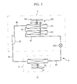
- FIG. 1 is a view schematically illustrating an air conditioner according to an embodiment
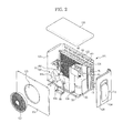
- FIG. 2 is a perspective view illustrating an outdoor unit of the air conditioner according to an embodiment.
- the air conditioner 1 includes an indoor unit 2 and an outdoor unit 3. Constituent elements of a refrigeration cycle system are mounted in the indoor unit 2 and the outdoor unit 3. These constituent elements are connected to one another via a refrigerant line 4.
- the indoor unit 2 is arranged in an indoor space of a building to cool or heat indoor air.
- the outdoor unit 3 is arranged outdoors to enable heat exchange between a refrigerant circulating through the refrigerant line 4 and outdoor air.
- the indoor unit 2 and the outdoor unit 3 may be separated from or integrated with each other.
- the indoor unit 2 includes an evaporator 10. As a fan 14 is driven by a motor 12, indoor air is fed toward the evaporator 10. A refrigerant passing through the evaporator 10 is evaporated by absorbing heat from the indoor air fed by the fan 14, and the high-temperature indoor air is cooled and is discharged into an indoor space.
- the outdoor unit 3 includes a compressor 20, a first heat exchanger 40, a second heat exchanger 60, and a blower 80.
- the compressor 20 is connected to the evaporator 10 via a refrigerant pipe 4a and compresses the evaporated refrigerant from the evaporator 10, generating a high-temperature and high-pressure refrigerant.
- the first exchanger 40 is arranged to undergo heat exchange with the surrounding air and is connected to the compressor 20 via a first connection pipe 4b.
- the compressed gas-phase refrigerant generated in the compressor 20 is introduced into the first heat exchanger 40 and is condensed by emitting heat to the surrounding air while passing through the first heat exchanger 40.
- the second heat exchanger 60 is connected to the first heat exchanger 40 via a second connection pipe 4c.
- the second heat exchanger 60 undergoes heat exchange with the surrounding air, to super-cool the refrigerant condensed by the first heat exchanger 40.
- the air conditioner 1 may achieve enhanced refrigerant super-cooling performance and thus, enhanced cooling capability thereof.
- the second heat exchanger 60 has an interior space to accommodate a liquid-phase refrigerant therein, the refrigerant line 4 may be filled with a great quantity of refrigerant. This may enhance the cooling capability of the air conditioner 1 and the super-cooling efficiency of the refrigerant without a significant increase in condensation pressure or evaporation pressure of the refrigerant.
- the blower 80 generates air flow toward the first heat exchanger 40 and the second heat exchanger 60 as a fan 84 is rotated by a motor 82.
- the second heat exchanger 60 may be arranged upstream of the first heat exchanger 40 in a blowing direction F of the blower 80.
- the above described configuration raises the overall efficiency of the first heat exchanger 40 and the second heat exchanger 60. Specifically, since the refrigerant inside the second heat exchanger 60 has a lower temperature than that of the refrigerant inside the first heat exchanger 40, it may be possible to raise the efficiency of the second heat exchanger 60 when the second heat exchanger 60 first undergoes heat exchange with the blown air. Also, even if a temperature of the blown air increases due to heat transferred from the second heat exchanger 60, the refrigerant inside the first heat exchanger 40 having a relatively higher temperature may efficiently undergo heat exchange with the increased temperature of air.
- the super-cooled refrigerant having passed through the second heat exchanger 60, is discharged from the second heat exchanger 60 through a third connection pipe 4d.
- the discharged super-cooled refrigerant is introduced into the expander 100 thus being lowered in pressure and then, is fed into the evaporator 10 through a refrigerant pipe 4e.
- FIG. 1 illustrates the expander 100 provided in the outdoor unit 3
- the expander 100 may be provided in the indoor unit 2.
- the outdoor unit 3 includes a box-shaped case 120.
- the case 120 is formed by coupling a front plate 122, a rear plate 124, both lateral plates 126 and 128, a top plate 130 and a bottom plate 132.
- the rear plate 124 and one lateral plate 126 may be formed of a single right-angled panel.
- the rear plate 124 has a suction grill 125 for suction of outdoor air.
- the other lateral plate 128 has an opening (not shown) for passage of the refrigerant pipes and electric wires for power supply.
- a cover 134 is coupled to the opening.
- the front plate 122 has a discharge hole 123 to discharge air out of the case 120.
- a fan guard 136 is coupled to the discharge hole 123 to prevent external impurities from entering the outdoor unit 3.
- the compressor 20, the first heat exchanger 40, the second heat exchanger 60 and the blower 80 are arranged inside the case 120.
- the blower 80 may include the axial flow fan 84 and the motor 82 to drive the axial flow fan 84.
- the blower 80 is fixed to a supporting member 86 and in turn, upper and lower ends of the supporting member 86 are coupled respectively to the top plate 130 and the bottom plate 132 so as to be coupled to the case 120.
- the axial flow fan 84 includes a hub 84a coupled to a rotating shaft of the motor 82, and blades 84b extending from the hub 84a in a radial direction and arranged in a circumferential direction of the hub 84a.
- a hub 84a coupled to a rotating shaft of the motor 82
- blades 84b extending from the hub 84a in a radial direction and arranged in a circumferential direction of the hub 84a.
- a partition 138 is used to separate a space for installation of the compressor 20 from a space for installation of the axial flow fan 84.
- An electric box 140 in which a variety of electric elements are accommodated, is arranged in an upper region of the space for installation of the compressor 20.
- the first heat exchanger 40 and the second heat exchanger 60 are arranged between the suction grill 125 and the axial flown fan 84 in the blowing direction F of the blower 80. Outdoor air suctioned through the suction grill 125 absorbs heat from the first heat exchanger 40 and the second heat exchanger 60 thus acting to cool the refrigerant and then, is discharged out of the case 120 through the discharge hole 123.
- FIG. 3 is a perspective view illustrating a fan, a first heat exchanger and a second heat exchanger included in the outdoor unit of the air conditioner according to an embodiment
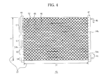
- FIG. 4 is a front view of the first heat exchanger
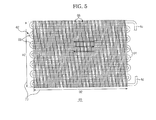
- FIG. 5 is a front view of the second heat exchanger.
- the first heat exchanger 40 is a so-called parallel flow heat exchanger.
- the first heat exchanger 40 includes a first header 42 and a second header 44 each defining a space therein, and a plurality of tubes 46 connecting the first header 42 and the second header 44 to each other.
- the first header 42, the second header 44 and the tubes 46 may be made of aluminum materials having superior heat transfer characteristics.
- the first header 42 and the second header 44 extend vertically and are horizontally spaced apart from each other by a predetermined distance on the drawing.
- the first connection pipe 4b and the second connection pipe 4c are connected respectively to upper and lower positions of the first header 42. The positions of the first connection pipe 4b and the second connection pipe 4c may be reversed.
- the high-temperature and high-pressure refrigerant compressed in the compressor 20 is introduced into the first heat exchanger 40 through the first connection pipe 4b. Also, the condensed refrigerant having passed through the first heat exchanger 40 is fed into the second heat exchanger 60 through the second connection pipe 4c.
- Each of the tubes 46 is in communication with the first header 42, and the other opposite end of each of the tubes 46 is in communication with the second header 44.
- Air paths 48 are defined between the respective tubes 46 to enable air passage.
- the first heat exchanger 40 has a first heat exchange region 50 in which the refrigerant inside the first heat exchanger 40 undergoes heat exchange with the air stream.
- the first heat exchange region 50 may be defined between the first header 42 and the second header 44 in consideration of the fact that most heat exchange occurs in the air paths 48 and the tubes 46 located between the first header 42 and the second header 44.
- Fins 52 to facilitate heat exchange are arranged in the air paths 48.
- the fins 52 may be made of aluminum materials, and may be soldered to the neighboring tubes 46.
- FIG. 4 illustrates waveform-shaped fins 52 extending between the first header 42 and the second header 44, the shape of the fins 52 may be changed.
- Baffles 54a, 54b and 54c are arranged in the first header 42 and the second header 44.
- the baffles 54a, 54b and 54c divide the tubes 46 of the first heat exchanger 40 into a plurality of groups.
- a first group G1 is divided by the baffle 54a arranged upstream in a refrigerant flow direction inside the first header 42.
- a second group G2 is defined between the baffle 54a and the baffle 54b arranged in the second header 44.
- a third group G3 is defined between the baffle 54b inside the second header 44 and the baffle 54c arranged downstream of the first header 42.
- a fourth group G4 is divided by the baffle 54c arranged downstream of the first header 42.
- the refrigerant passes through the first heat exchanger 40, the refrigerant flows in the same given direction when passing through the tubes of the same group, but flows in different directions when passing through the tubes of the neighboring two groups.
- the high-temperature and high-pressure refrigerant introduced into the first header 42 through the first connection pipe 4b, undergoes heat exchange with the surrounding air while flowing to the second header 44 through the tubes 46 of the first group G1.
- the refrigerant having passed through the tubes 46 of the first group G1, is merged into the second header 44 and thereafter, is distributed into the tubes 46 of the second group G2.
- the distributed refrigerant undergoes heat exchange with the surrounding air while flowing to the first header 44 through the tubes 46 of the second group G2.
- the refrigerant flows to the second header 44 through the tubes 46 of the third group G3 and returns to the first header 42 through the tubes 46 of the fourth group G4, thereby being discharged through the second connection pipe 4c.
- FIG. 4 illustrates an embodiment in which the first to fourth groups G1, G2, G3 and G4 include 6, 5, 3 and 2 tubes respectively.
- the high-temperature and high-pressure refrigerant present upstream of the first heat exchanger 40 shows a relatively faster flow rate, whereas the condensed refrigerant present downstream of the first heat exchanger 40 shows a relatively slower flow rate. Accordingly, when the refrigerant flows through a great number of tubes upstream of the first heat exchanger 40, heat exchange ability and efficiency may be enhanced.
- FIG. 4 illustrates an embodiment in which the three baffles 54a, 54b and 54c divide the tubes into the four groups G1, G2, G3 and G4, the number of the baffles may be changed according to the number of groups to be divided.
- the refrigerant introduced into the second heat exchanger 60 through the second connection pipe 4c is super-cooled while passing through the second heat exchanger 60, and is discharged out of the second heat exchanger 60 through the third connection pipe 4d.
- the second heat exchanger 60 includes a serpentine heat exchange pipe 62 that is bent plural times between the second connection pipe 4c and the third connection pipe 4d.
- the heat exchange pipe 62 has a first bent portion 64 and a second bent portion 66 arranged at opposite sides.
- the refrigerant having passed through the first bent portion 64 flows to the second bent portion 66, and the flow direction of the refrigerant is reversed at the second bent portion 66.
- the refrigerant having passed through the second bent portion 66 flows to the first bent portion 64 and the flow direction of the refrigerant is again reversed at the first bent portion 64 so as to flow to the second bent portion 66.
- the second heat exchanger 60 has a second heat exchange region 70 in which the refrigerant inside the second heat exchanger 60 undergoes heat exchange with the air stream.
- the second heat exchange region 70 may be defined between the first bent portion 64 and the second bent portion 66 in consideration of the fact that most heat exchange occurs in the heat exchange pipe 62 between the first bent portion 64 and the second bent portion 66.
- Fins 68 to facilitate heat exchange are coupled to the heat exchange pipe 62.
- the fins 68 may be press-fitted into the heat exchange pipe 62.
- the fins 68 are made of thin metal plates having superior heat transfer characteristics and may be arranged between the first bent portion 64 and the second bent portion 66.
- the second heat exchanger 60, the first heat exchanger 40 and the axial flow fan 84 are arranged sequentially in the blowing direction F.
- the first heat exchange region 50 of the first heat exchanger 40 and the second heat exchange region 70 of the second heat exchanger 60 may overlap each other. This arrangement may provide the outdoor unit 3 with compactness and the second heat exchanger 60 with enhanced efficiency, causing enhanced super-cooling performance and cooling capability of the air conditioner 1.
- the first heat exchange region 50 and the second heat exchange region 70 may have substantially the same shape and size.
- a distance D1 between the first header 42 and the second header 44 of the first heat exchanger 40 may be substantially equal to a distance D2 between the first bent portion 64 and the second bent portion 66 of the second heat exchanger 60.
- a distance H1 between the uppermost and lowermost tubes of the first heat exchanger 40 i.e. a height of the first heat exchange region 50
- a distance H2 between upper and lower ends of the heat exchange pipe 62 of the second heat exchanger 60 i.e. a height of the second heat exchange region 70).
- the second connection pipe 4c may be connected to the first header 42 at one side of the first heat exchanger 40 and also, may be connected to the second heat exchanger 60 at one side of the second heat exchanger 60 corresponding to the side of the first heat exchanger 40.
- This configuration simplifies piping between the first heat exchanger 40 and the second heat exchanger 60, realizing compactness of the outdoor unit 3.
- the air conditioner according to the embodiment having the above described configuration may exhibit enhanced capability and efficiency, resulting in excellent performance without using a large size outdoor unit.
Landscapes
- Engineering & Computer Science (AREA)
- Mechanical Engineering (AREA)
- General Engineering & Computer Science (AREA)
- Physics & Mathematics (AREA)
- Thermal Sciences (AREA)
- Life Sciences & Earth Sciences (AREA)
- Sustainable Development (AREA)
- Chemical & Material Sciences (AREA)
- Combustion & Propulsion (AREA)
- Other Air-Conditioning Systems (AREA)
Applications Claiming Priority (1)
| Application Number | Priority Date | Filing Date | Title |
|---|---|---|---|
| KR1020090112434A KR20110055840A (ko) | 2009-11-20 | 2009-11-20 | 공기조화기와 그 실외기 |
Publications (2)
| Publication Number | Publication Date |
|---|---|
| EP2330366A2 true EP2330366A2 (de) | 2011-06-08 |
| EP2330366A3 EP2330366A3 (de) | 2011-08-03 |
Family
ID=43608619
Family Applications (1)
| Application Number | Title | Priority Date | Filing Date |
|---|---|---|---|
| EP10189837A Withdrawn EP2330366A3 (de) | 2009-11-20 | 2010-11-03 | Klimaanlage und Außeneinheit dafür |
Country Status (4)
| Country | Link |
|---|---|
| US (1) | US20110126581A1 (de) |
| EP (1) | EP2330366A3 (de) |
| KR (1) | KR20110055840A (de) |
| CN (1) | CN102072528A (de) |
Cited By (2)
| Publication number | Priority date | Publication date | Assignee | Title |
|---|---|---|---|---|
| JP2013087976A (ja) * | 2011-10-13 | 2013-05-13 | Daikin Industries Ltd | 空気調和装置 |
| WO2025032265A1 (es) * | 2023-08-08 | 2025-02-13 | Masam Purificadores, S.L. | Sistema de bomba de calor |
Families Citing this family (21)
| Publication number | Priority date | Publication date | Assignee | Title |
|---|---|---|---|---|
| US9551498B2 (en) * | 2012-06-28 | 2017-01-24 | Samsung Electronics Co., Ltd. | Indoor unit of air conditioner and method of controlling the air conditioner |
| KR101989096B1 (ko) * | 2013-06-18 | 2019-06-13 | 엘지전자 주식회사 | 공기조화기의 열교환기 |
| KR101989097B1 (ko) * | 2012-11-05 | 2019-06-13 | 엘지전자 주식회사 | 공기조화기의 열교환기 |
| KR20140142802A (ko) * | 2013-06-04 | 2014-12-15 | 삼성전자주식회사 | 실외 열교환기 및 공기조화기 |
| KR102174510B1 (ko) * | 2013-11-05 | 2020-11-04 | 엘지전자 주식회사 | 냉장고의 냉각 사이클 |
| JP6177193B2 (ja) * | 2014-06-06 | 2017-08-09 | 三菱電機株式会社 | 空気調和機の室外機 |
| CN106152253A (zh) * | 2015-03-24 | 2016-11-23 | 台达电子工业股份有限公司 | 空调装置 |
| KR20160131577A (ko) * | 2015-05-08 | 2016-11-16 | 엘지전자 주식회사 | 공기조화기의 열교환기 |
| ITUB20152983A1 (it) * | 2015-08-07 | 2017-02-07 | De Longhi Appliances Srl | Condizionatore portatile perfezionato |
| CN105258388A (zh) * | 2015-10-30 | 2016-01-20 | 苏州必信空调有限公司 | 一种节能高效制冷系统 |
| JP6139760B1 (ja) * | 2016-07-13 | 2017-05-31 | 株式会社岡村製作所 | 冷却装置 |
| JP6880901B2 (ja) * | 2017-03-27 | 2021-06-02 | ダイキン工業株式会社 | 熱交換器ユニット |
| CN109000389B (zh) * | 2017-11-03 | 2021-07-27 | 株式会社电装 | 冷凝器及具备该冷凝器的制冷系统 |
| CN108692384B (zh) * | 2018-06-05 | 2020-06-16 | 海信(广东)空调有限公司 | 一种窗式空调器 |
| JP7658711B2 (ja) * | 2019-02-12 | 2025-04-08 | ナブテスコ株式会社 | 空気圧縮装置 |
| CN110345636A (zh) * | 2019-07-30 | 2019-10-18 | 西安交通大学 | 热回收式空气源热泵热水器循环系统及工作方法 |
| IT201900021486A1 (it) * | 2019-11-18 | 2021-05-18 | Mitsubishi Electric Hydronics & It Cooling Systems S P A | Disposizione migliorata di ciclo di refrigerazione raffreddato ad aria |
| US11262112B2 (en) | 2019-12-02 | 2022-03-01 | Johnson Controls Technology Company | Condenser coil arrangement |
| CN113251502A (zh) * | 2021-06-11 | 2021-08-13 | 青岛腾远设计事务所有限公司 | 一种冷凝换热单元和节能多联机 |
| CN114623628A (zh) * | 2022-04-21 | 2022-06-14 | 合肥圣三松冷热技术有限公司 | 一种热泵循环系统及其工作方法 |
| CN220103272U (zh) * | 2023-04-18 | 2023-11-28 | 特灵空调系统(中国)有限公司 | 气候控制系统的侧排放室外单元 |
Family Cites Families (16)
| Publication number | Priority date | Publication date | Assignee | Title |
|---|---|---|---|---|
| US1870457A (en) * | 1930-12-19 | 1932-08-09 | Grigsby Grunow Co | Refrigerating apparatus |
| US2181354A (en) * | 1939-07-28 | 1939-11-28 | Winters John | Condenser for refrigerators |
| DE3938842A1 (de) * | 1989-06-06 | 1991-05-29 | Thermal Waerme Kaelte Klima | Verfluessiger fuer ein kaeltemittel einer fahrzeugklimaanlage |
| JP3051420B2 (ja) * | 1990-03-02 | 2000-06-12 | 株式会社日立製作所 | 空気調和装置,その装置に用いられる室内熱交換器の製造方法 |
| DE4205681C2 (de) * | 1992-02-25 | 2001-05-31 | Behr Gmbh & Co | Verfahren zum Betreiben einer Klimaanlage und Klimaanlage hierfür |
| US5682944A (en) * | 1992-11-25 | 1997-11-04 | Nippondenso Co., Ltd. | Refrigerant condenser |
| US5590539A (en) * | 1993-11-26 | 1997-01-07 | Omega Enterprises Inc. | Refrigeration apparatus and methods |
| US5546761A (en) * | 1994-02-16 | 1996-08-20 | Nippondenso Co., Ltd. | Receiver-integrated refrigerant condenser |
| US5660050A (en) * | 1995-07-10 | 1997-08-26 | Russell Coil Company | Refrigeration condenser, receiver subcooler system |
| EP0961092A1 (de) * | 1998-05-27 | 1999-12-01 | Huai-Wei Wang | Verflüssigereinheit |
| US5946932A (en) * | 1998-06-03 | 1999-09-07 | Wang; Huai-Wei | Multistage condensing structure |
| JP3649236B2 (ja) * | 2003-10-09 | 2005-05-18 | ダイキン工業株式会社 | 空気調和装置 |
| CN1782554A (zh) * | 2004-11-29 | 2006-06-07 | 乐金电子(天津)电器有限公司 | 空调器的室外机系统 |
| GB0614942D0 (en) * | 2006-07-27 | 2006-09-06 | British American Tobacco Co | Apparatus and method for packing smoking articles |
| CN1959330A (zh) * | 2006-09-15 | 2007-05-09 | 东莞高宝铝材制品厂有限公司 | 一种高科技复合材料环保节能空调制冷系统冷凝器和散热网 |
| JP4803199B2 (ja) * | 2008-03-27 | 2011-10-26 | 株式会社デンソー | 冷凍サイクル装置 |
-
2009
- 2009-11-20 KR KR1020090112434A patent/KR20110055840A/ko not_active Withdrawn
-
2010
- 2010-11-03 EP EP10189837A patent/EP2330366A3/de not_active Withdrawn
- 2010-11-18 US US12/926,459 patent/US20110126581A1/en not_active Abandoned
- 2010-11-18 CN CN201010553525XA patent/CN102072528A/zh active Pending
Non-Patent Citations (1)
| Title |
|---|
| None |
Cited By (2)
| Publication number | Priority date | Publication date | Assignee | Title |
|---|---|---|---|---|
| JP2013087976A (ja) * | 2011-10-13 | 2013-05-13 | Daikin Industries Ltd | 空気調和装置 |
| WO2025032265A1 (es) * | 2023-08-08 | 2025-02-13 | Masam Purificadores, S.L. | Sistema de bomba de calor |
Also Published As
| Publication number | Publication date |
|---|---|
| CN102072528A (zh) | 2011-05-25 |
| EP2330366A3 (de) | 2011-08-03 |
| KR20110055840A (ko) | 2011-05-26 |
| US20110126581A1 (en) | 2011-06-02 |
Similar Documents
| Publication | Publication Date | Title |
|---|---|---|
| EP2330366A2 (de) | Klimaanlage und Außeneinheit dafür | |
| US9702637B2 (en) | Heat exchanger, indoor unit, and refrigeration cycle apparatus | |
| AU2014260968B2 (en) | Indoor unit for air conditioning device | |
| JP4827882B2 (ja) | 熱交換器モジュール、熱交換器、室内ユニット及び空調冷凍装置、並びに熱交換器の製造方法 | |
| US20140102131A1 (en) | Outdoor unit of refrigeration system | |
| CN102297480B (zh) | 空调的室内单元 | |
| EP2835587B1 (de) | Wärmetauscher für klimaanlagenvorrichtung sowie klimaanlagenvorrichtung | |
| CN103238037A (zh) | 热交换器和安装有热交换器的一体化空调机 | |
| JP2008261615A (ja) | 熱交換器、熱交換装置、冷蔵庫、空調装置 | |
| JP6466047B1 (ja) | 熱交換器及び空気調和装置 | |
| US11885570B2 (en) | Cooling system | |
| EP1953480B1 (de) | Wärmetauscher für ausseneinheit | |
| JP2018162938A (ja) | 熱交換器又は冷凍装置 | |
| CN212390507U (zh) | 空调器 | |
| KR100502303B1 (ko) | 나선형 열교환장치 | |
| JP2006336909A (ja) | 凝縮器及びこれを用いた空気調和機用室内ユニット | |
| JP2018048769A (ja) | 熱交換器 | |
| EP4283221A1 (de) | Wärmetauscher | |
| WO2019151115A1 (ja) | 冷凍装置の熱源ユニット | |
| CN213020011U (zh) | 空调器 | |
| WO2019116838A1 (ja) | 熱交換ユニット及びこれを搭載する空気調和装置 | |
| CN113970133A (zh) | 空调器 | |
| TWI810896B (zh) | 除濕裝置 | |
| JPH0926252A (ja) | 熱交換ユニット及び冷凍装置 | |
| WO2023233572A1 (ja) | 熱交換器及び冷凍サイクル装置 |
Legal Events
| Date | Code | Title | Description |
|---|---|---|---|
| PUAI | Public reference made under article 153(3) epc to a published international application that has entered the european phase |
Free format text: ORIGINAL CODE: 0009012 |
|
| AK | Designated contracting states |
Kind code of ref document: A2 Designated state(s): AL AT BE BG CH CY CZ DE DK EE ES FI FR GB GR HR HU IE IS IT LI LT LU LV MC MK MT NL NO PL PT RO RS SE SI SK SM TR |
|
| AX | Request for extension of the european patent |
Extension state: BA ME |
|
| PUAL | Search report despatched |
Free format text: ORIGINAL CODE: 0009013 |
|
| AK | Designated contracting states |
Kind code of ref document: A3 Designated state(s): AL AT BE BG CH CY CZ DE DK EE ES FI FR GB GR HR HU IE IS IT LI LT LU LV MC MK MT NL NO PL PT RO RS SE SI SK SM TR |
|
| AX | Request for extension of the european patent |
Extension state: BA ME |
|
| RIC1 | Information provided on ipc code assigned before grant |
Ipc: F25B 40/02 20060101ALI20110627BHEP Ipc: F25B 39/04 20060101ALI20110627BHEP Ipc: F25B 6/04 20060101AFI20110627BHEP |
|
| 17P | Request for examination filed |
Effective date: 20120113 |
|
| RAP1 | Party data changed (applicant data changed or rights of an application transferred) |
Owner name: SAMSUNG ELECTRONICS CO., LTD. |
|
| STAA | Information on the status of an ep patent application or granted ep patent |
Free format text: STATUS: THE APPLICATION HAS BEEN WITHDRAWN |
|
| 18W | Application withdrawn |
Effective date: 20131009 |