EP2327622A1 - Unmanned submarine and device for connecting a fibre optic cable to an unmanned submarine - Google Patents
Unmanned submarine and device for connecting a fibre optic cable to an unmanned submarine Download PDFInfo
- Publication number
- EP2327622A1 EP2327622A1 EP10190567A EP10190567A EP2327622A1 EP 2327622 A1 EP2327622 A1 EP 2327622A1 EP 10190567 A EP10190567 A EP 10190567A EP 10190567 A EP10190567 A EP 10190567A EP 2327622 A1 EP2327622 A1 EP 2327622A1
- Authority
- EP
- European Patent Office
- Prior art keywords
- cable
- connection
- underwater vehicle
- strain relief
- mine
- Prior art date
- Legal status (The legal status is an assumption and is not a legal conclusion. Google has not performed a legal analysis and makes no representation as to the accuracy of the status listed.)
- Granted
Links
- 239000000835 fiber Substances 0.000 title claims abstract description 26
- 238000007667 floating Methods 0.000 claims description 20
- 230000003287 optical effect Effects 0.000 claims description 13
- 238000004804 winding Methods 0.000 claims description 9
- 230000009182 swimming Effects 0.000 description 20
- 230000006378 damage Effects 0.000 description 19
- 239000013307 optical fiber Substances 0.000 description 15
- 239000002360 explosive Substances 0.000 description 7
- 238000005452 bending Methods 0.000 description 6
- 238000000926 separation method Methods 0.000 description 6
- 238000005422 blasting Methods 0.000 description 3
- 238000000034 method Methods 0.000 description 3
- 238000002360 preparation method Methods 0.000 description 3
- 238000011084 recovery Methods 0.000 description 3
- XLYOFNOQVPJJNP-UHFFFAOYSA-N water Substances O XLYOFNOQVPJJNP-UHFFFAOYSA-N 0.000 description 3
- 238000005520 cutting process Methods 0.000 description 2
- 238000005474 detonation Methods 0.000 description 2
- 230000003213 activating effect Effects 0.000 description 1
- 230000006978 adaptation Effects 0.000 description 1
- 230000005540 biological transmission Effects 0.000 description 1
- 238000007664 blowing Methods 0.000 description 1
- 238000010276 construction Methods 0.000 description 1
- 230000001419 dependent effect Effects 0.000 description 1
- 238000001514 detection method Methods 0.000 description 1
- 230000007613 environmental effect Effects 0.000 description 1
- 239000006260 foam Substances 0.000 description 1
- 231100001261 hazardous Toxicity 0.000 description 1
- 230000001939 inductive effect Effects 0.000 description 1
- 238000003780 insertion Methods 0.000 description 1
- 230000037431 insertion Effects 0.000 description 1
- 230000003137 locomotive effect Effects 0.000 description 1
- 238000004519 manufacturing process Methods 0.000 description 1
- 230000001404 mediated effect Effects 0.000 description 1
- 238000005065 mining Methods 0.000 description 1
- 229920001296 polysiloxane Polymers 0.000 description 1
- 230000001681 protective effect Effects 0.000 description 1
- 239000007787 solid Substances 0.000 description 1
Images

Classifications
-
- G—PHYSICS
- G02—OPTICS
- G02B—OPTICAL ELEMENTS, SYSTEMS OR APPARATUS
- G02B6/00—Light guides; Structural details of arrangements comprising light guides and other optical elements, e.g. couplings
- G02B6/44—Mechanical structures for providing tensile strength and external protection for fibres, e.g. optical transmission cables
- G02B6/4439—Auxiliary devices
- G02B6/4471—Terminating devices ; Cable clamps
-
- B—PERFORMING OPERATIONS; TRANSPORTING
- B63—SHIPS OR OTHER WATERBORNE VESSELS; RELATED EQUIPMENT
- B63C—LAUNCHING, HAULING-OUT, OR DRY-DOCKING OF VESSELS; LIFE-SAVING IN WATER; EQUIPMENT FOR DWELLING OR WORKING UNDER WATER; MEANS FOR SALVAGING OR SEARCHING FOR UNDERWATER OBJECTS
- B63C11/00—Equipment for dwelling or working underwater; Means for searching for underwater objects
- B63C11/34—Diving chambers with mechanical link, e.g. cable, to a base
-
- G—PHYSICS
- G02—OPTICS
- G02B—OPTICAL ELEMENTS, SYSTEMS OR APPARATUS
- G02B6/00—Light guides; Structural details of arrangements comprising light guides and other optical elements, e.g. couplings
- G02B6/44—Mechanical structures for providing tensile strength and external protection for fibres, e.g. optical transmission cables
- G02B6/4401—Optical cables
- G02B6/4415—Cables for special applications
- G02B6/4427—Pressure resistant cables, e.g. undersea cables
Definitions
- the invention relates to a device for connecting an optical fiber cable to an unmanned underwater vehicle and an unmanned underwater vehicle, which is controllable by means of an optical fiber cable, which is trackable by a carrier platform,
- Unmanned Underwater Vehicles are used for a variety of underwater tasks called missions, e.g. in the civilian sector, for the exploration and examination of the seabed, the control of cables and pipelines on the seabed and the recovery of lost equipment.
- unmanned underwater vehicles are used in particular for mine reconnaissance and mine destruction, but are also used for such operations, which pose a high risk to manned missions.
- the underwater vehicle is remotely controlled by means of a connecting cable, which is tracked to the underwater vehicle by a carrier platform, for example, a surface ship.
- the remote control cable is usually a powerful optical fiber cable.
- guided underwater vehicles are used in two variants via fiber optic cables. A first variant is used for closer identification of an object found eg by a sonar, eg a mine, and then retrieved back to the carrier platform. For demining a second variant is used, which additionally carries an explosive charge and after finding of the previously identified target at the destruction of the target at the same time destroyed itself.
- mine hunting drones ie used for mine control unmanned underwater vehicles, the loss of the underwater vehicle with regard to the desired clearing success is accepted.
- fiber optic swimming cables are used to control underwater vehicles, which have the required for obtaining the underwater vehicle tensile strength.
- a low weight of the swimming cable is desired to avoid a drop in the cable.
- US 2008/0087186 A1 discloses a method for the destruction of a localized mine, wherein for the purpose of blasting the mine an unmanned underwater vehicle cooperates as a primary vehicle with an unmanned, remote-controlled underwater vehicle as a secondary vehicle, which is equipped with an explosive charge.
- primary and secondary vehicles are used as an autonomously operating tandem, in which the secondary vehicle of remotely controlled from the primary vehicle.
- the secondary vehicle is designed as a one-way vehicle and equipped with an explosive charge for mine destruction and an associated detonator.
- the propulsion energy is supplied to the secondary vehicle from an energy source of the primary vehicle via a connection cable, which also serves to transmit steering signals to a steering device of the secondary vehicle and to transmit a detonator activating trigger signal.
- the tandem drives as an autonomous, ie independent from a platform, tandem independently to a previously located mine.
- the primary vehicle brings the secondary vehicle by remote control directly to the mine and triggers by appropriate ignition signal from the detonator of the explosive charge.
- connection cable Similar to a direct control of a destructible mine hunting drone via a connection cable from a platform, the connection cable is destroyed even with the known insertion of a primary and secondary vehicle simultaneously with a loss of the secondary vehicle. It is therefore to replace the underwater vehicle and the connection cable after a mine clearance mission with a corresponding cost.
- a mine clearance method and equipment system is known with an autonomous power unmanned underwater vehicle for transporting a mine clearance charge, wherein a control cable for controlling the underwater vehicle from a ship's ship is simultaneously used as an ignition cable.
- the combined control and ignition cable is galvanic or non-contact, in particular inductive, coupled with an igniter of the mine destruction charge.
- the connection cable is subdivided into two partial lengths corresponding to the action radius. The first part length is housed on a separate cable spool and is dropped with the mine destruction charge. The return is done by means of cable control over the second part length, which is housed on a second cable reel in the underwater vehicle.
- the first and second part lengths of the combined control and ignition cable of the known device are connected by means of a connector (e.g., plug). After triggering the detonation on the connection cable is lost in the known device, the first part length of the combined control and ignition cable with the deposited mine destruction charge. In a blast but also the second part of the length of the connection cable is connected to the mine destruction charge and is destroyed or at least damaged so far that it must be replaced for cost reasons.
- a connector e.g., plug
- DD 300 526 A5 discloses a cable-towable underwater implement carrier, in particular a mine-hunting device, which tows a control cable which is unreeled from a cable reel located on the underwater device carrier and deposited on the seabed.
- the known device is based on the fact that when positioning the underwater device carrier and Drehmanövern due to the lack of a cable pulling force, the risk of damage directly exiting the fuselage of the underwater equipment control cable by protruding fuselage parts, eg. Rudder and rudder, but especially by the drive propeller, is extremely high.
- the control cable is guided within a arranged on the control cable outlet opening of the underwater device flexible support hose with appropriate bending stiffness.
- the present invention is based on the problem to provide a device for connecting an optical fiber cable to an unmanned underwater vehicle and an unmanned underwater vehicle, which reduce the cost of a mission of the underwater vehicle.
- the optical fiber cable is connected via a connection device with the underwater vehicle, which has a connection cable and connection elements at the ends of the connection cable on the one hand for the optical fiber cable and on the other hand for the underwater vehicle.
- connection cable is expediently a second optical fiber cable. Since its loss is accepted, it is advantageously provided with a short length, but sufficient to reliably prevent damage to the fiber optic swimming cable connected to the carrier platform during a blast.
- the support platform of the underwater vehicle may be stationary or mobile, such as on board a ship, set up.
- the very long fiber optic cable of the carrier platform compared to the connecting cable can be used for further missions and is then equipped with a new connection device, so that the cost of a mission, in particular a mine clearance with a mine hunting drone of og. second variant, be reduced.
- the disposable component can be stored in larger quantities on the support platform. Also, the number of possible missions for the support platform can be increased because the long fiber optic cable can be reused and instead of replacing the long fiber optic cable, a variety of connection cables can be stored.
- connection device is also easy to handle, since it requires only a few handles to connect on the one hand to the long fiber optic cable of the carrier platform and on the other hand to the underwater vehicle.
- connection device also reduces the potential for error in the preparation of a mission.
- the optical fiber cable which is adapted to the connection device is advantageously a swimming cable.
- a swimming cable prevents the connection cable of the underwater vehicle from hitting obstacles on the seabed.
- the connection cable can also be designed as a swimming cable.
- the ends of the connection cable each carry connector, wherein the connection elements of the connection cable strain relief for the cable ends, so that on the one hand, a stable and robust optical fiber connection between the carrier platform and the underwater vehicle and thus the probability of failure is reduced.
- the strain relief elements at the ends ensure reliable recovery of the cable and the underwater vehicle.
- the strain relief connection can simplify recovery of the submersible. In a mine clearance mission associated with a loss of the mine hunting drone, in the event of a fault, e.g. In the event of a failure to ignore, the underwater vehicle should be quickly found and cleared using the connection provided by fiber optic cables and connection cables.
- the cost-effective connection device also has the advantage of full compatibility with existing fiber optic cable systems.
- connection device Due to the fixed properties of the connection device, it is possible to provide a reliable application according to the environmental conditions give. It has been shown that there is a linear relationship with the situation-specific parameters of the distance to the target and the countercurrent for the underwater vehicle to be considered. If the range of use for swim cables and connection cables, which is linearly limited due to the distance to the target and the countercurrent, is exceeded, a mission using two coils to dispense the fiber optic cable is recommended. In this variant, a coil for dispensing the connecting cable is provided both on the support platform and on the underwater vehicle in order to create a strain-relieved and therefore stable connection.
- a suitability of the inventive control of the underwater vehicle by optical fiber cable and connection device can be assumed to be reliable below a target distance of several hundred meters and a counterflow of a few nodes.
- connection element for the optical waveguide cable comprises a floating body which receives a portion of the connection cable with a strain relief element and has a further strain relief element for receiving the optical waveguide cable.
- the connecting element of the connecting cable for the underwater vehicle is advantageously formed with a body elongated radially to the cable for arrangement on a rear chamber of the underwater vehicle, which carries the strain relief for the connectable to the underwater vehicle end of the connecting cable.
- This body has a cable guide for the connection cable, through which the cable end is guided for connection to the underwater vehicle.
- the cable guide is advantageously formed by a funnel-shaped design of a cable channel in the connection element.
- the wall of the funnel rounded to effectively protect the fiber optic cable from damage by kinking and also to keep the potential bending of the fiber within a range where optical reflection occurs in the fiber optic cable.
- This design of the connecting element allows in a few steps a strain-relieved and less prone to failure adaptation of the underwater vehicle.
- connection device is advantageously formed separable from the underwater vehicle, so that the connection device according to the invention is suitable for missions with reusable vehicles. For example. For example, catching the cable on an underwater obstacle, such as a wreck, may make it impossible to retrieve the vehicle so that the underwater vehicle can be salvaged by appropriately controlled disconnection of the cable connection.
- This separation can e.g. by a miniature snap device for blowing off the connection cable or a remote controllable cutting device for cutting the connection cable done.
- Such separators may be provided at one or both ends of the connection cable or even therebetween.
- a controlled detachment of the connection device from the underwater vehicle also permits a partially cable-guided and partially autonomous mission of the underwater vehicle. For example. can be cable-guided to a certain depth and then operated by cable separation even at greater depths.
- the controlled detachment of the connection device from the underwater vehicle allows, for example, work on pipelines, which are to be carried out regularly autonomously.
- the cable separation takes place in a particular embodiment of the floating body of the connection device, so that the swimming cable can be obtained.
- the swimming cable and the connection device can be separated in a controlled manner if the connecting cable and its connecting elements are designed with a lower tensile strength than the swimming cable. It can then by targeted construction of tensile forces, eg. By operating the winch of the swimming cable, a separation of the connection device are brought about.
- the strain relief on the connection elements of the connection cable can be arranged or adjusted so that different tensile strengths allow a targeted detachment of the cable.
- connection device The costs of producing the connection device according to the invention are further reduced if all connection elements have identical strain relief elements.
- the strain relief elements are tuned to the cross sections of each connected cable. It is advantageous to match the cross section of the connecting cable to the cross section of the floating cable, so that cables with the same cross sections and identical strain relief can be used.
- a flexible tube is arranged on the connection element for the underwater vehicle, through which the connection cable is passed.
- the flexible tube therefore points away from the underwater vehicle in the installed position and prevents excessive bending of the connection cable in the area of the vehicle drive.
- the flexible tube is advantageously arranged on the body having the cable guide.
- the connecting cable is wound onto a winding carrier which can be placed on an adapter provided on the carrier platform.
- the disposable component can thus be stored in an orderly manner and used quickly if necessary.
- the cable wrap also ensures safe delivery of the connection cable during the launch phase of the underwater vehicle.
- the disposable component with the cable wrap is also easy and quick to handle.
- the user When preparing the mission, the user only has to connect the float to the fiber optic cable and the connection cable to the underwater vehicle, as well as the cable wrap of the connection cable put on the adapter, which can be attached, for example, to the railing of a watercraft.
- the cable length of the connection cable is first unwound with, for example, a few dozen meters of length. Once the connection cable is in the water, the floating body pulls the floating cable into the water as a force-fit connection between the connection cable and the swim cable and the underwater vehicle begins to take the swim cable from the cable winch.
- Fig. 1 schematically an unmanned underwater vehicle 1 is shown, which is controlled by a cable connection from a support platform 2.
- the carrier platform 2 is in the embodiment, a surface ship.
- the carrier platform is an underwater vehicle, eg a submarine, a floating platform, eg a non-powered vehicle, such as a tender, a transportable container or any form of mobile or stationary platform, for example, set ashore on the coast or at the seabed, for example, in order to be able to free from mines affected by mining waterways, especially straits.
- the underwater vehicle 1 is a mine-hunting drone which may be equipped with an explosive charge for mine-clearance missions or with various mine-detection sensors.
- the cable connection for controlling the underwater vehicle 1 consists of an optical fiber swimming cable 3, which with a in Fig. 2 separately shown connection device 4 is connected to the underwater vehicle 1.
- the optical fiber swimming cable 3 is tracked by a cable winch 5 on board the watercraft 2.
- a strain relief 6, which is assigned in the embodiment of the cable winch 5, ensures a zugentlasteten connection of the swimming cable 3 to a control unit 7 of the support platform. 2
- connection device 4 consists of an optical waveguide cable as connection cable 8, at the ends 9, 10 connection elements are arranged, namely at the end 9 a float 11 and at the other end 10, a connection element 12 for connection to the underwater vehicle.
- a plug 13, 14 is arranged in each case. Before the underwater vehicle 1 is exposed, the plug 13 assigned to the floating body 11 is connected to a corresponding plug-in element 15 of the floating cable 3. The plug 14 at the other end 10 of the connecting cable 8 is connected to a corresponding contact 16 of the underwater vehicle 1.
- the floating body 11 is a solid body which receives the end 9 of the connection cable 8 with a strain relief element 17.
- the floating body 11 has a further strain relief element 18 for receiving the swimming cable 3.
- Both strain relief elements 17, 18 are attached to the floating body 11 so that tensile forces between the connected cables 3, 8 are imparted by the fixed float 11.
- the floating body 11 is designed as an elongated body, at the ends of each of the strain reliefs 17, 18 are fixed so that the cable ends in the space between the strain relief elements 17, 18 can be easily plugged together and a strain relief connector is made. In this way it is avoided that the locomotive mine hunting drone 1 separates the connector on the float or it comes with a collection of the floating cable 3 to an unwanted separation of the connecting cable.
- the plug connection between the connecting cable 8 and the swimming cable 3 and the associated strain relief elements 17, 18 are received in the interior of the floating body 11.
- the float 11 is aerodynamically shaped and has in the present embodiment in its interior a pressure-resistant with respect to the depth of use of the underwater vehicle, acting as a buoyant foam.
- the end 9 of the connecting cable 8 is guided over a formed on the floating body 11 anti-buckling 19 into the interior of the floating body 11, so that a kinking of the connecting cable 8 is avoided.
- the connecting element 12 for the underwater vehicle 1 is formed with a body radially formed in sections for placement on a rear chamber 21 of the underwater vehicle 1, wherein the body has a cable guide 20 for the connection cable 8.
- the end 10 of the connecting cable 8 is guided in the rear chamber 21 defined.
- the cable guide 20 prevents damage to the fiber optic cable by sharp bending.
- the cable guide is formed at one or both ends thereof so that the minimum bending radii to be maintained for the optical waveguide are actually maintained.
- the (respective) end preferably has a convexly curved funnel-shaped section.
- the connecting element 12 carries in the region of the cable guide 20, a strain relief element 22, which relieves the end 10 of the connection cable 8 during a mission and protects against unwanted detachment.
- a flexible tube 23 On the opposite side of the strain relief element 22 with the cable guide 20 body is arranged a flexible tube 23 through which the connection cable 8 extends.
- the flexible tube 23, which is preferably made of silicone, protects the connecting cable 8 against excessive kinking in the region of the connecting element 12 and keeps the connection cable 8 in particular away from the drive located in the rear region of the underwater vehicle 1.
- connection cable 8 may be equipped with a protective jacket which extends over the entire length of the connection cable.
- connection device 4 is a disposable component that can be produced inexpensively, which consists of the connection cable 8 and the float 11 and the connection element 12 for the mine hunting drone.
- the component includes a cable winding 24 with a winding support 25 on which the connecting cable 8 is wound.
- the winding support 25 is in the embodiment, a cone-shaped coil from which the connecting cable 8 can be easily removed at the start of a mission.
- the winding support 25 is in a simple operation on an adapter 26 of the support platform 2 ( Fig. 1 ) attached.
- the adapter 26 is attached in the present embodiment to the railing 27 of the surface ship, but may also be located elsewhere in the ship.
- connection device 4 is also lost as a disposable component in a mine hunting mission due to the destruction of the underwater vehicle, but damage to the long fiber optic cable of the carrier platform is avoided by the detonation.
- the long swimming cable is located according to the length of the connecting cable 8 at a safe distance from the underwater vehicle and can therefore be used again.
- the connecting cable 8 is sufficiently long to protect the swimming cable in a blasting from damage.
- connection device 4 The cost-effective production and ease of handling of the connection device 4 is further promoted by the fact that all strain reliefs 17, 18, 22 on the float 11 and the connection device 4 are designed to be identical to the connection element 12.
- connection device 4 is easy to handle in the preparation of a mission, so that sources of error are reduced.
- the user only has to Mount the floating cable 3 in the floating body 11 or the strain relief element 18 provided in the floating body 11 and then adapt the underwater vehicle via the flexible tube 23 and the body of the connecting element 12 equipped with the cable guide 20.
- the underwater vehicle After the underwater vehicle has been exposed and started, it first takes the length of the connecting cable 8 from the cable winding 24 and then pulls over the float 11, the actual swimming cable 3 into the water. Subsequently, the underwater vehicle takes the fiber optic swimming cable 3 of the cable winch 5 of the support platform 2.
- the strain reliefs 17, 18 in the float 11 for a transmission of tensile forces between connecting cable 8 and swimming cable 3 without affecting the fiber optic connector.
- connection element 12 an optical waveguide channel 28 is formed, whose end portion facing the cable end 10 is part of the cable guide 20.
- the end portion of the optical waveguide channel 28 is funnel-shaped with a convexly rounded contour, wherein the rounding radii avoid unwanted bending of the optical fiber cable and thus damage the connection cable 8.
- the radial body of the connection element 12 and the cable guide 20 formed in the body thus jointly form an approximately S-shaped contour.
Landscapes
- Physics & Mathematics (AREA)
- General Physics & Mathematics (AREA)
- Optics & Photonics (AREA)
- Laying Of Electric Cables Or Lines Outside (AREA)
- Light Guides In General And Applications Therefor (AREA)
- Mechanical Coupling Of Light Guides (AREA)
Abstract
Description
Die Erfindung betrifft eine Einrichtung zum Anschluss eines Lichtwellenleiterkabels an ein unbemanntes Unterwasserfahrzeug sowie ein unbemanntes Unterwasserfahrzeug, welches mittels eines Lichtwellenleiterkabels steuerbar ist, das von einer Trägerplattform nachführbar ist,The invention relates to a device for connecting an optical fiber cable to an unmanned underwater vehicle and an unmanned underwater vehicle, which is controllable by means of an optical fiber cable, which is trackable by a carrier platform,
Unbemannte Unterwasserfahrzeuge (UUV, Unmanned Underwater Vehicle) werden für eine Vielzahl von Aufgaben unter Wasser, sog. Missionen, eingesetzt, z.B. im zivilen Bereich für das Absuchen und Untersuchen des Meeresbodens, die Kontrolle von Kabeln und Rohrleitungen auf dem Meeresboden sowie die Bergung von verloren gegangenen Geräten. Im militärischen Bereich werden unbemannte Unterwasserfahrzeuge insbesondere zur Minenaufklärung und Minenvernichtung eingesetzt, aber auch für solche Einsätze herangezogen, die für bemannte Missionen ein hohes Risiko darstellen.Unmanned Underwater Vehicles (UUV) are used for a variety of underwater tasks called missions, e.g. in the civilian sector, for the exploration and examination of the seabed, the control of cables and pipelines on the seabed and the recovery of lost equipment. In the military sector, unmanned underwater vehicles are used in particular for mine reconnaissance and mine destruction, but are also used for such operations, which pose a high risk to manned missions.
Als ferngesteuertes Unterwasserfahrzeug bzw. sog. Remotely Operated Vehicle (ROV) wird das Unterwasserfahrzeug mittels eines Verbindungskabels ferngelenkt, welches dem Unterwasserfahrzeug von einer Trägerplattform, bspw. einem Überwasserschiff, nachgeführt wird. Das Fernlenkkabel ist dabei üblicherweise ein leistungsfähiges Lichtwellenleiterkabel. Auf dem Gebiet der Minenjagd werden über Lichtwellenleiterkabel ferngelenkte Unterwasserfahrzeuge in zwei Varianten verwendet. Eine erste Variante wird zur näheren Identifikation eines, bspw. durch Sonar, aufgefundenen Objekts, z.B. einer Mine eingesetzt und anschließend zur Trägerplattform zurückgeholt. Zur Minenräumung wird eine zweite Variante eingesetzt, welche zusätzlich eine Sprengladung trägt und nach Auffinden des vorher identifizierten Ziels bei der Vernichtung des Ziels zugleich selbst zerstört wird. Bei derartigen Minenjagddrohnen, d.h. zur Minenbekämpfung eingesetzten unbemannten Unterwasserfahrzeugen, wird der Verlust des Unterwasserfahrzeugs im Hinblick auf den gewünschten Räumerfolg in Kauf genommen.As a remote-controlled underwater vehicle or so-called. Remotely Operated Vehicle (ROV), the underwater vehicle is remotely controlled by means of a connecting cable, which is tracked to the underwater vehicle by a carrier platform, for example, a surface ship. The remote control cable is usually a powerful optical fiber cable. In the field of mine hunting, guided underwater vehicles are used in two variants via fiber optic cables. A first variant is used for closer identification of an object found eg by a sonar, eg a mine, and then retrieved back to the carrier platform. For demining a second variant is used, which additionally carries an explosive charge and after finding of the previously identified target at the destruction of the target at the same time destroyed itself. In such mine hunting drones, ie used for mine control unmanned underwater vehicles, the loss of the underwater vehicle with regard to the desired clearing success is accepted.
Bei derartigen Minenjagddrohnen führt allerdings auch ein Fehlschlagen der Minenräumung zum Verlust des Unterwasserfahrzeugs, da es aus Sicherheitsgründen nicht mehr an Bord genommen werden und seine mitgeführte Sprengladung gezündet wird. Auch die o.g. erste Variante von Unterwasserfahrzeugen kann bei Minenjagdmissionen verloren gehen, wenn nämlich durch das Unterwasserfahrzeug der Auslösemechanismus einer aufgefundenen Seemine aktiviert wird.In such mine hunting drones, however, a failure of mine clearance leads to the loss of the underwater vehicle, since it will no longer be taken on board for safety reasons and his entrained explosive charge is ignited. Also the o.g. first variant of submersibles can be lost in mine hunting missions, namely, when activated by the underwater vehicle, the triggering mechanism of a discovered maritime mine.
Gemäß dem Stand der Technik werden zur Steuerung von Unterwasserfahrzeugen Lichtwellenleiter-Schwimmkabel eingesetzt, welche die zum Einholen des Unterwasserfahrzeugs erforderliche Zugfestigkeit aufweisen. Dabei ist ein geringes Gewicht des Schwimmkabels erwünscht, um ein Absinken des Kabels zu vermeiden.According to the prior art, fiber optic swimming cables are used to control underwater vehicles, which have the required for obtaining the underwater vehicle tensile strength. In this case, a low weight of the swimming cable is desired to avoid a drop in the cable.
Die Kosten einer Minenräummission sind regelmäßig hoch, zumal bei einem Verlust des Unterwasserfahrzeugs gleichzeitig das Lichtwellenleiterkabel zerstört wird und ersetzt werden muss. Dabei muss gegebenenfalls ein Großteil des Kabels von der Winsch genommen und ein neues Lichtwellenleiterkabel eingerichtet und aufgespult werden, was neben den Beschaffungskosten für das Kabel mit hohem Arbeitsaufwand verbunden ist.The cost of a mine clearance mission is regularly high, especially as a loss of the underwater vehicle at the same time the fiber optic cable is destroyed and must be replaced. If necessary, a large part of the cable must be removed from the winch and set up a new fiber optic cable and reeled, which is connected in addition to the cost of procurement of the cable with a lot of work.
Ähnlich einer unmittelbaren Steuerung einer zerstörbaren Minenjagddrohne über ein Verbindungskabel von einer Plattform wird auch bei dem bekannten Einsetzen eines Primär- und Sekundärfahrzeugs gleichzeitig mit einem Verlust des Sekundärfahrzeugs das Verbindungskabel zerstört. Es sind daher nach einer Minenräummission mit entsprechendem Kostenaufwand das Unterwasserfahrzeug und das Verbindungskabel zu ersetzen.Similar to a direct control of a destructible mine hunting drone via a connection cable from a platform, the connection cable is destroyed even with the known insertion of a primary and secondary vehicle simultaneously with a loss of the secondary vehicle. It is therefore to replace the underwater vehicle and the connection cable after a mine clearance mission with a corresponding cost.
Aus
Die erste und die zweite Teillänge des kombinierten Steuer- und Zündkabels der bekannten Einrichtung sind mittels eines Verbindungselements (z.B. Stecker) verbunden. Nach Auslösung der Sprengung über das Verbindungskabel geht bei der bekannten Einrichtung die erste Teillänge des kombinierten Steuer- und Zündkabels mit der abgelegten Minenvernichtungsladung verloren. Bei einer Sprengung ist aber auch die zweite Teillänge des Verbindungskabels mit der Minenvernichtungsladung verbunden und wird zerstört bzw. wenigstens soweit beschädigt, dass es aus Kostengründen ersetzt werden muss.The first and second part lengths of the combined control and ignition cable of the known device are connected by means of a connector (e.g., plug). After triggering the detonation on the connection cable is lost in the known device, the first part length of the combined control and ignition cable with the deposited mine destruction charge. In a blast but also the second part of the length of the connection cable is connected to the mine destruction charge and is destroyed or at least damaged so far that it must be replaced for cost reasons.
Der vorliegenden Erfindung liegt das Problem zugrunde, eine Einrichtung zum Anschluss eines Lichtwellenleiterkabels an ein unbemanntes Unterwasserfahrzeug sowie ein unbemanntes Unterwasserfahrzeug zu schaffen, welche die Kosten einer Mission des Unterwasserfahrzeugs reduzieren.
The present invention is based on the problem to provide a device for connecting an optical fiber cable to an unmanned underwater vehicle and an unmanned underwater vehicle, which reduce the cost of a mission of the underwater vehicle.
Diese Aufgabe wird erfindungsgemäß durch eine Einrichtung zum Anschluss eines Lichtwellenleiterkabels mit den Merkmalen des Patentanspruchs 1 und ein unbemanntes Unterwasserfahrzeug mit den Merkmalen des Patentanspruchs 8 gelöst.This object is achieved by a device for connecting a fiber optic cable with the features of
Erfindungsgemäß ist das Lichtwellenleiterkabel über eine Anschlusseinrichtung mit dem Unterwasserfahrzeug verbunden, welche ein als Anschlusskabel und Anschlusselemente an den Enden des Anschlusskabels einerseits für das Lichtwellenleiterkabel und andererseits für das Unterwasserfahrzeug aufweist. Dadurch wird vermieden, dass bei einem Verlust des Unterwasserfahrzeugs durch Sprengungen das in der Regel sehr lange Lichtwellenleiterkabel zur Steuerung des Unterwasserfahrzeugs zerstört wird. Es geht lediglich die Anschlusseinrichtung verloren, welche jedoch als Einweg-Bauteil kostengünstig vorgefertigt werden kann.According to the invention the optical fiber cable is connected via a connection device with the underwater vehicle, which has a connection cable and connection elements at the ends of the connection cable on the one hand for the optical fiber cable and on the other hand for the underwater vehicle. This avoids that in a loss of the underwater vehicle by blasting the usually very long fiber optic cable for controlling the underwater vehicle is destroyed. It is only lost the connection device, which, however, can be prefabricated inexpensively as a disposable component.
Das Anschlusskabel ist zweckmäßig ein zweites Lichtwellenleiterkabel. Da sein Verlust in Kauf genommen wird, wird es vorteilhaft mit einer geringen Länge bereitgestellt, welche aber ausreichend ist, um bei einer Sprengung eine Beschädigung des an die Trägerplattform angeschlossenen Lichtwellenleiter-Schwimmkabels zuverlässig zu vermeiden. Die Trägerplattform des Unterwasserfahrzeugs kann dabei stationär oder mobil, etwa an Bord eines Schiffes, eingerichtet sein.The connection cable is expediently a second optical fiber cable. Since its loss is accepted, it is advantageously provided with a short length, but sufficient to reliably prevent damage to the fiber optic swimming cable connected to the carrier platform during a blast. The support platform of the underwater vehicle may be stationary or mobile, such as on board a ship, set up.
Das im Vergleich zum Anschlusskabel sehr lange Lichtwellenleiterkabel der Trägerplattform kann für weitere Missionen verwendet werden und wird dann mit einer neuen Anschlusseinrichtung ausgerüstet, so dass die Kosten einer Mission, insbesondere einer Minenräumung mit einer Minenjagddrohne der o.g. zweiten Variante, reduziert werden.The very long fiber optic cable of the carrier platform compared to the connecting cable can be used for further missions and is then equipped with a new connection device, so that the cost of a mission, in particular a mine clearance with a mine hunting drone of og. second variant, be reduced.
Das Einweg-Bauteil kann in größerer Stückzahl an der Trägerplattform bevorratet werden. Auch kann die Zahl der möglichen Missionen für die Trägerplattform erhöht werden, da das lange Lichtwellenleiterkabel wieder verwendet werden kann und anstelle eines Ersatzes für das lange Lichtwellenleiterkabel eine Vielzahl von Anschlusskabeln gelagert werden kann.The disposable component can be stored in larger quantities on the support platform. Also, the number of possible missions for the support platform can be increased because the long fiber optic cable can be reused and instead of replacing the long fiber optic cable, a variety of connection cables can be stored.
Die Anschlusseinrichtung ist auch einfach zu handhaben, da es lediglich weniger Handgriffe zum Anschließen einerseits an das lange Lichtwellenleiterkabel der Trägerplattform und andererseits an das Unterwasserfahrzeug bedarf.The connection device is also easy to handle, since it requires only a few handles to connect on the one hand to the long fiber optic cable of the carrier platform and on the other hand to the underwater vehicle.
Durch die einfache Handhabung der Anschlusseinrichtung wird auch das Fehlerpotential bei der Vorbereitung einer Mission reduziert.The simple handling of the connection device also reduces the potential for error in the preparation of a mission.
Das Lichtwellenleiterkabel, das an die Anschlusseinrichtung adaptiert wird, ist vorteilhaft ein Schwimmkabel. Ein Schwimmkabel verhindert, dass die Verbindungsleitung des Unterwasserfahrzeugs an Hindernissen am Meeresgrund hängen bleibt. Mit diesen vorteilhaften Eigenschaften kann auch das Anschlusskabel als Schwimmkabel ausgeführt sein.The optical fiber cable which is adapted to the connection device is advantageously a swimming cable. A swimming cable prevents the connection cable of the underwater vehicle from hitting obstacles on the seabed. With these advantageous properties, the connection cable can also be designed as a swimming cable.
Bei einer besonderen Ausführungsform tragen die Enden des Anschlusskabels jeweils Verbindungsstecker, wobei die Anschlusselemente des Anschlusskabels Zugentlastungselemente für die Kabelenden aufweisen, so dass einerseits eine stabile und robuste Lichtwellenleiterverbindung zwischen der Trägerplattform und dem Unterwasserfahrzeug besteht und so die Ausfallwahrscheinlichkeit reduziert wird. Andererseits ist durch die Zugentlastungselemente an den Enden eine zuverlässige Bergung des Kabels und des Unterwasserfahrzeugs gewährleistet. Bei Verwendung von rücksetzbaren Zündern, bspw. EFI-Zündern (Electrical Fuse Ignitor) kann durch die zugentlastete Verbindung die Bergung des Unterwasserfahrzeugs vereinfacht werden. Bei einer Minenräummission, die mit einem Verlust der Minenjagddrohne verbunden ist, kann im Fehlerfall, z.B. bei einem Zündversager, das Unterwasserfahrzeug schnell mit Hilfe der durch Lichtwellenleiterkabel und Anschlusskabel gegebenen Verbindung gefunden und geräumt werden.In a particular embodiment, the ends of the connection cable each carry connector, wherein the connection elements of the connection cable strain relief for the cable ends, so that on the one hand, a stable and robust optical fiber connection between the carrier platform and the underwater vehicle and thus the probability of failure is reduced. On the other hand, the strain relief elements at the ends ensure reliable recovery of the cable and the underwater vehicle. When using resettable igniters, such as EFI (Electrical Fuse Ignitor) igniters, the strain relief connection can simplify recovery of the submersible. In a mine clearance mission associated with a loss of the mine hunting drone, in the event of a fault, e.g. In the event of a failure to ignore, the underwater vehicle should be quickly found and cleared using the connection provided by fiber optic cables and connection cables.
Die kostengünstige Anschlusseinrichtung hat zudem den Vorteil der vollständigen Kompatibilität zu bereits bestehenden Lichtwellenleiterkabel-Systemen.The cost-effective connection device also has the advantage of full compatibility with existing fiber optic cable systems.
Durch die festliegenden Eigenschaften der Anschlusseinrichtung ist es möglich, eine zuverlässige Einsatzempfehlung entsprechend den Umweltbedingungen zu geben. Es hat sich dabei gezeigt, dass bei den zu berücksichtigenden, situationsbezogenen Parametern der Entfernung zum Ziel und der Gegenströmung für das Unterwasserfahrzeug ein linearer Zusammenhang besteht. Wird der durch Zielentfernung und Gegenströmung linear begrenzte Einsatzbereich für Schwimmkabel und Anschlusskabel überschritten, so ist eine Mission unter Einsatz von zwei Spulen zur Abgabe des Lichtwellenleiterkabels zu empfehlen. Bei dieser Variante ist sowohl an der Trägerplattform als auch an dem Unterwasserfahrzeug eine Spule zur Abgabe des Verbindungskabels vorgesehen, um eine zugentlastete und damit stabile Verbindung zu schaffen. Aufgrund eines linearen Zusammenhangs der situationsbezogenen Parameter, nämlich Zielentfernung und Gegenströmung, kann unterhalb einer Zielentfernung von mehreren hundert Metern sowie einer Gegenströmung von wenigen Knoten eine Eignung der erfindungsgemäßen Steuerung des Unterwasserfahrzeugs durch Lichtwellenleiterkabel und Anschlusseinrichtung als zuverlässig angenommen werden.Due to the fixed properties of the connection device, it is possible to provide a reliable application according to the environmental conditions give. It has been shown that there is a linear relationship with the situation-specific parameters of the distance to the target and the countercurrent for the underwater vehicle to be considered. If the range of use for swim cables and connection cables, which is linearly limited due to the distance to the target and the countercurrent, is exceeded, a mission using two coils to dispense the fiber optic cable is recommended. In this variant, a coil for dispensing the connecting cable is provided both on the support platform and on the underwater vehicle in order to create a strain-relieved and therefore stable connection. Due to a linear relationship of the situation-related parameters, namely target distance and countercurrent, a suitability of the inventive control of the underwater vehicle by optical fiber cable and connection device can be assumed to be reliable below a target distance of several hundred meters and a counterflow of a few nodes.
Vorteilhaft umfasst das Anschlusselement für das Lichtwellenleiterkabel einen Schwimmkörper, welcher mit einem Zugentlastungselement einen Abschnitt des Anschlusskabels aufnimmt und ein weiteres Zugentlastungselement zur Aufnahme des Lichtwellenleiterkabels aufweist. Dadurch wird die Steckverbindung zwischen dem Lichtwellenleiterkabel und dem Anschlusskabel vor Zugkräften und damit einer ungewollten Trennung geschützt, da Zugkräfte über den festen Schwimmkörper zwischen den beiden verbundenen Kabeln vermittelt werden.Advantageously, the connection element for the optical waveguide cable comprises a floating body which receives a portion of the connection cable with a strain relief element and has a further strain relief element for receiving the optical waveguide cable. As a result, the connector between the optical fiber cable and the connecting cable is protected from tensile forces and thus an unwanted separation, as tensile forces are mediated by the fixed float between the two connected cables.
Das Anschlusselement des Anschlusskabels für das Unterwasserfahrzeug ist vorteilhafterweise mit einem radial zum Kabel gestreckten Körper zur Anordnung an einer Heckkammer des Unterwasserfahrzeugs ausgebildet, welcher das Zugentlastungselement für das am Unterwasserfahrzeug anschließbare Ende des Anschlusskabels trägt. Dieser Körper weist eine Kabelführung für das Anschlusskabel auf, durch die das Kabelende zum Anschluss an das Unterwasserfahrzeug geführt ist.The connecting element of the connecting cable for the underwater vehicle is advantageously formed with a body elongated radially to the cable for arrangement on a rear chamber of the underwater vehicle, which carries the strain relief for the connectable to the underwater vehicle end of the connecting cable. This body has a cable guide for the connection cable, through which the cable end is guided for connection to the underwater vehicle.
Die Kabelführung ist vorteilhaft durch eine trichterförmige Gestaltung eines Kabelkanals im Anschlusselement gebildet. Dabei ist die Wandung des Trichters gerundet ausgebildet, um das Lichtwellenleiterkabel effektiv vor Beschädigungen durch Abknicken zu schützen und außerdem die mögliche Biegung des Lichtwellenleiters innerhalb eines Bereichs zu halten, in dem optische Reflektion im Lichtwellenleiterkabel erfolgt. Diese Gestaltung des Anschlusselements erlaubt mit wenigen Handgriffen eine zugentlastete und wenig störanfällige Adaption des Unterwasserfahrzeugs.The cable guide is advantageously formed by a funnel-shaped design of a cable channel in the connection element. Here is the wall of the funnel rounded to effectively protect the fiber optic cable from damage by kinking and also to keep the potential bending of the fiber within a range where optical reflection occurs in the fiber optic cable. This design of the connecting element allows in a few steps a strain-relieved and less prone to failure adaptation of the underwater vehicle.
Die Anschlusseinrichtung ist vorteilhaft vom Unterwasserfahrzeug trennbar ausgebildet, so dass sich die erfindungsgemäße Anschlusseinrichtung für Missionen mit wiederverwendbaren Fahrzeugen eignet. Bspw. kann ein Verfangen des Kabels an einem Unterwasserhindernis, wie einem Wrack, ein Rückholen des Fahrzeugs unmöglich machen, so dass durch eine entsprechend gesteuerte Trennung der Kabelverbindung das Unterwasserfahrzeug gerettet werden kann.The connection device is advantageously formed separable from the underwater vehicle, so that the connection device according to the invention is suitable for missions with reusable vehicles. For example. For example, catching the cable on an underwater obstacle, such as a wreck, may make it impossible to retrieve the vehicle so that the underwater vehicle can be salvaged by appropriately controlled disconnection of the cable connection.
Diese Trennung kann z.B. durch eine Miniatursprengeinrichtung zum Absprengen des Anschlusskabels oder eine fernsteuerbare Schneideinrichtung zum Durchtrennen des Anschlusskabels erfolgen. Derartige Trenneinrichtungen können an einem oder beiden Enden des Anschlusskabels oder auch dazwischen vorgesehen sein.This separation can e.g. by a miniature snap device for blowing off the connection cable or a remote controllable cutting device for cutting the connection cable done. Such separators may be provided at one or both ends of the connection cable or even therebetween.
Auch erlaubt eine kontrollierte Ablösung der Anschlusseinrichtung vom Unterwasserfahrzeug eine teilweise kabelgeführte und teilweise autonome Mission des Unterwasserfahrzeugs. Bspw. kann bis zu einer gewissen Tiefe kabelgeführt und anschließend durch Kabeltrennung auch in größeren Tiefen operiert werden. Die kontrollierte Ablösung der Anschlusseinrichtung vom Unterwasserfahrzeug erlaubt bspw. Arbeiten an Pipelines, die regelmäßig autonom durchzuführen sind.A controlled detachment of the connection device from the underwater vehicle also permits a partially cable-guided and partially autonomous mission of the underwater vehicle. For example. can be cable-guided to a certain depth and then operated by cable separation even at greater depths. The controlled detachment of the connection device from the underwater vehicle allows, for example, work on pipelines, which are to be carried out regularly autonomously.
Die Kabeltrennung erfolgt bei einer besonderen Ausführungsform am Schwimmkörper der Anschlusseinrichtung, so dass das Schwimmkabel eingeholt werden kann. Das Schwimmkabel und die Anschlusseinrichtung können kontrolliert getrennt werden, wenn das Anschlusskabel und dessen Anschlusselemente mit geringerer Zugfestigkeit als das Schwimmkabel ausgebildet werden. Es kann dann durch gezielten Aufbau von Zugkräften, bspw. durch Betätigen der Winsch des Schwimmkabels, eine Abtrennung der Anschlussvorrichtung herbeigeführt werden. Hierzu können auch die Zugentlastungselemente an den Anschlusselementen des Anschlusskabels so angeordnet oder eingestellt werden, dass unterschiedliche Zugfestigkeiten ein gezieltes Ablösen des Kabels ermöglichen.The cable separation takes place in a particular embodiment of the floating body of the connection device, so that the swimming cable can be obtained. The swimming cable and the connection device can be separated in a controlled manner if the connecting cable and its connecting elements are designed with a lower tensile strength than the swimming cable. It can then by targeted construction of tensile forces, eg. By operating the winch of the swimming cable, a separation of the connection device are brought about. For this purpose, the strain relief on the connection elements of the connection cable can be arranged or adjusted so that different tensile strengths allow a targeted detachment of the cable.
Die Kosten der Herstellung der erfindungsgemäßen Anschlusseinrichtung sind weiter reduziert, wenn alle Anschlusselemente baugleiche Zugentlastungselemente aufweisen. Die Zugentlastungselemente sind dabei mit den Querschnitten der jeweils angebundenen Kabel abgestimmt. Es ist vorteilhaft, den Querschnitt des Anschlusskabels dem Querschnitt des Schwimmkabels anzugleichen, so dass Kabel mit gleichen Querschnitten und baugleiche Zugentlastungselemente eingesetzt werden können.The costs of producing the connection device according to the invention are further reduced if all connection elements have identical strain relief elements. The strain relief elements are tuned to the cross sections of each connected cable. It is advantageous to match the cross section of the connecting cable to the cross section of the floating cable, so that cables with the same cross sections and identical strain relief can be used.
Um eine Beschädigung des Anschlusskabels durch den Antrieb des Unterwasserfahrzeugs bzw. ein Aufwickeln des Anschlusskabels um den Antrieb zu vermeiden, ist an dem Anschlusselement für das Unterwasserfahrzeugs eine flexible Röhre angeordnet, durch welche das Anschlusskabel hindurchgeführt ist. Die flexible Röhre weist demnach in Einbaulage vom Unterwasserfahrzeug weg und verhindert ein übermäßiges Abknicken des Anschlusskabels im Bereich des Fahrzeugsantriebs. Die flexible Röhre ist vorteilhaft an dem die Kabelführung aufweisenden Körper angeordnet.In order to avoid damage to the connection cable by the drive of the underwater vehicle or a winding of the connection cable to the drive, a flexible tube is arranged on the connection element for the underwater vehicle, through which the connection cable is passed. The flexible tube therefore points away from the underwater vehicle in the installed position and prevents excessive bending of the connection cable in the area of the vehicle drive. The flexible tube is advantageously arranged on the body having the cable guide.
Besonders vorteilhaft ist das Anschlusskabel auf einen Wickelträger aufgewickelt, welcher einem an der Trägerplattform vorgesehen Adapter aufsetzbar ist. Das Einweg-Bauteil kann somit geordnet gelagert und im Bedarfsfall schnell eingesetzt werden. Der Kabelwickel gewährleistet zudem eine sichere Abgabe des Anschlusskabels während der Startphase des Unterwasserfahrzeugs.Particularly advantageously, the connecting cable is wound onto a winding carrier which can be placed on an adapter provided on the carrier platform. The disposable component can thus be stored in an orderly manner and used quickly if necessary. The cable wrap also ensures safe delivery of the connection cable during the launch phase of the underwater vehicle.
Das Einwegbauteil mit dem Kabelwickel ist auch leicht und schnell zu handhaben. Bei der Vorbereitung der Mission muss der Anwender lediglich den Schwimmkörper an das Lichtwellenleiterkabel und das Anschlusskabel an das Unterwasserfahrzeug anschließen sowie den Kabelwickel des Anschlusskabels auf den Adapter setzen, der bspw. an der Reling eines Wasserfahrzeugs befestigt sein kann. Nachdem das Unterwasserfahrzeug ausgesetzt und gestartet ist, wird zunächst die Kabellänge des Anschlusskabels mit bspw. einigen wenigen Dutzend Metern Länge abgespult. Nachdem sich das Anschlusskabel im Wasser befindet, zieht der Schwimmkörper als kraftschlüssige Verbindung zwischen Anschlusskabel und Schwimmkabel das Schwimmkabel ins Wasser und das Unterwasserfahrzeug beginnt das Schwimmkabel von der Kabelwinsch zu nehmen.The disposable component with the cable wrap is also easy and quick to handle. When preparing the mission, the user only has to connect the float to the fiber optic cable and the connection cable to the underwater vehicle, as well as the cable wrap of the connection cable put on the adapter, which can be attached, for example, to the railing of a watercraft. After the underwater vehicle has been suspended and started, the cable length of the connection cable is first unwound with, for example, a few dozen meters of length. Once the connection cable is in the water, the floating body pulls the floating cable into the water as a force-fit connection between the connection cable and the swim cable and the underwater vehicle begins to take the swim cable from the cable winch.
Weitere vorteilhafte Ausführungsformen ergeben sich aus den Unteransprüchen sowie den anhand der Zeichnung näher erläuterten Ausführungsbeispielen der Erfindung. In der Zeichnung zeigt:
- Fig. 1
- eine schematische Darstellung eines Wasserfahrzeugs und eines unbemannten Unterwasserfahrzeugs, welche mittels eines Lichtwellenleiterkabels und einer erfindungsgemäßen Anschlusseinrichtung miteinander verbunden sind,
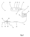
- Fig. 2
- eine schematische Darstellung einer Einrichtung zum Anschluss eines Lichtwellenleiterkabels an ein unbemanntes Unterwasserfahrzeug.
- Fig. 1
- a schematic representation of a watercraft and an unmanned underwater vehicle, which are interconnected by means of a fiber optic cable and a connection device according to the invention,
- Fig. 2
- a schematic representation of a device for connecting an optical fiber cable to an unmanned underwater vehicle.
In
Die Kabelverbindung zur Steuerung des Unterwasserfahrzeugs 1 besteht aus einem Lichtwellenleiter-Schwimmkabel 3, welches mit einer in
Die Anschlusseinrichtung 4 besteht aus einem Lichtwellenleiterkabel als Anschlusskabel 8, an dessen Enden 9, 10 Anschlusselemente angeordnet sind, nämlich am Ende 9 ein Schwimmkörper 11 und am anderen Ende 10 ein Anschlusselement 12 zum Anschluss an das Unterwasserfahrzeug 1.The
An beiden Enden 9, 10 des Anschlusskabels ist jeweils ein Stecker 13, 14 angeordnet. Vor dem Aussetzen des Unterwasserfahrzeugs 1 wird der dem Schwimmkörper 11 zugeordnete Stecker 13 mit einem entsprechenden Steckelement 15 des Schwimmkabels 3 verbunden. Der Stecker 14 am anderen Ende 10 des Anschlusskabels 8 wird an einen entsprechenden Kontakt 16 des Unterwasserfahrzeugs 1 angeschlossen.At both ends 9, 10 of the connecting cable, a
Der Schwimmkörper 11 ist ein fester Körper, welcher das Ende 9 des Anschlusskabels 8 mit einem Zugentlastungselement 17 aufnimmt. Der Schwimmkörper 11 weist ein weiteres Zugentlastungselement 18 zur Aufnahme des Schwimmkabels 3 auf. Beide Zugentlastungselemente 17, 18 sind am Schwimmkörper 11 befestigt, so dass Zugkräfte zwischen den angeschlossenen Kabeln 3, 8 durch den festen Schwimmkörper 11 vermittelt werden. Der Schwimmkörper 11 ist als länglicher Körper ausgeführt, an dessen Enden jeweils die Zugentlastungen 17, 18 befestigt sind, so dass die Kabelenden in dem Raum zwischen den Zugentlastungselementen 17, 18 leicht zusammen gesteckt werden können und eine zugentlastete Steckverbindung hergestellt wird. Auf diese Weise ist vermieden, dass die sich fortbewegende Minenjagddrohne 1 die Steckverbindung am Schwimmkörper trennt oder aber es bei einem Einholen des Schwimmkabels 3 zu einer unerwünschten Trennung des Verbindungskabels kommt.The floating
Die Steckverbindung zwischen dem Anschlusskabel 8 und dem Schwimmkabel 3 sowie die dazugehörigen Zugentlastungselemente 17, 18 sind im Inneren des Schwimmkörpers 11 aufgenommen. Der Schwimmkörper 11 ist strömungsgünstig geformt und weist im vorliegenden Ausführungsbeispiel in seinem Inneren einen im Hinblick auf die Einsatztiefe des Unterwasserfahrzeugs druckbeständigen, als Auftriebskörper wirkenden Schaum auf. Das Ende 9 des Anschlusskabels 8 ist über einen am Schwimmkörper 11 ausgeformten Knickschutz 19 ins Innere des Schwimmkörpers 11 geführt, so dass ein Abknicken des Anschlusskabels 8 vermieden ist.The plug connection between the connecting
Das Anschlusselement 12 für das Unterwasserfahrzeug 1 ist mit einem abschnittsweise radial ausgebildeten Körper zur Anordnung an einer Heckkammer 21 des Unterwasserfahrzeugs 1 ausgebildet, wobei der Körper eine Kabelführung 20 für das Anschlusskabel 8 aufweist. Durch die Kabelführung 20 ist das Ende 10 des Anschlusskabels 8 definiert in die Heckkammer 21 geführt. Die Kabelführung 20 verhindert Beschädigungen der Lichtwellenleitung durch scharfes Abknicken. Ferner ist die Kabelführung an einem oder beiden ihrer Enden derart geformt, dass die für die Lichtwellenleitung einzuhaltenden minimalen Biegeradien tatsächlich eingehalten werden. Dazu weist das (jeweilige) Ende vorzugsweise einen konvex gewölbten trichterförmigen Abschnitt auf.The connecting
Das Anschlusselement 12 trägt im Bereich der Kabelführung 20 ein Zugentlastungselement 22, welches während einer Mission das Ende 10 des Anschlusskabels 8 entlastet und vor einer ungewollten Ablösung schützt. Auf der dem Zugentlastungselement 22 gegenüberliegenden Seite mit der Kabelführung 20 ausgestalteten Körpers ist eine flexible Röhre 23 angeordnet, durch welche das Anschlusskabel 8 verläuft. Die flexible Röhre 23, die vorzugsweise aus Silikon besteht, schützt das Anschlusskabel 8 vor übermäßigem Abknicken im Bereich des Anschlusselements 12 und hält das Anschlusskabel 8 insbesondere von dem im Heckbereich der Unterwasserfahrzeug 1 liegenden Antrieb fern.The connecting
In einem nicht dargestellten Ausführungsbeispiel kann anstelle einer flexiblen Röhre das Anschlusskabel 8 mit einem Schutzmantel ausgestattet sein, welches sich über die Gesamtlänge des Anschlusskabels erstreckt.In an embodiment not shown, instead of a flexible tube, the
Die in
Die Anschlusseinrichtung 4 geht als Einweg-Bauteil bei einer Minenjagdmission aufgrund der Zerstörung des Unterwasserfahrzeugs ebenfalls verlustig, wobei jedoch eine Beschädigung des langen Lichtwellenleiterkabels der Trägerplattform durch die Detonation vermieden wird. Das lange Schwimmkabel befindet sich entsprechend der Länge des Anschlusskabels 8 in sicherer Entfernung zum Unterwasserfahrzeug und kann daher wieder verwendet werden. Das Anschlusskabel 8 ist ausreichend lang, um das Schwimmkabel bei einer Sprengung vor Beschädigungen zu schützen.The
Die kostengünstige Herstellung und leichte Handhabbarkeit der Anschlusseinrichtung 4 wird weiter dadurch gefördert, dass sämtliche Zugentlastungen 17, 18, 22 an dem Schwimmkörper 11 und der Anschlusseinrichtung 4 dem Anschlusselement 12 baugleich ausgeführt sind.The cost-effective production and ease of handling of the
Die Anschlusseinrichtung 4 ist bei der Vorbereitung einer Mission einfach zu handhaben, so dass Fehlerquellen reduziert werden. Der Anwender muss lediglich das Schwimmkabel 3 in dem Schwimmkörper 11 bzw. dem im Schwimmkörper 11 vorgesehen Zugentlastungselement 18 montieren und anschließend das Unterwasserfahrzeug über die flexible Röhre 23 und den mit der Kabelführung 20 ausgestatteten Körper des Anschlusselements 12 adaptieren. Nachdem das Unterwasserfahrzeug ausgesetzt wurde und gestartet wurde, nimmt es zunächst die Länge des Anschlusskabels 8 von dem Kabelwickel 24 und zieht anschließend über den Schwimmkörper 11 das eigentliche Schwimmkabel 3 ins Wasser. Anschließend nimmt das Unterwasserfahrzeug das Lichtwellenleiter-Schwimmkabel 3 von der Kabelwinsch 5 der Trägerplattform 2. Dabei sorgen die Zugentlastungen 17, 18 im Schwimmkörper 11 für eine Übertragung der Zugkräfte zwischen Anschlusskabel 8 und Schwimmkabel 3 ohne Beeinträchtigung der Glasfaser-Steckverbindung.The
In dem Anschlusselement 12 ist ein Lichtwellenleiterkanal 28 ausgebildet, dessen dem Kabelende 10 zugewandter Endabschnitts Teil der Kabelführung 20 ist. Der Endabschnitt des Lichtwellenleiterkanals 28 ist trichterförmig mit einer konvex gerundeten Kontur ausgebildet, wobei die Rundungsradien ein ungewolltes Abknicken des Lichtwellenleiterkabels und damit Beschädigungen des Anschlusskabels 8 vermeiden. Der radiale Körper des Anschlusselements 12 und die in dem Körper ausgebildete Kabelführung 20 bilden so gemeinsam eine etwa s-förmige Kontur aus.In the
Sämtliche in der Figurenbeschreibung, in den Ansprüchen und in der Beschreibungseinleitung genannten Merkmale sind sowohl einzeln als auch in beliebiger Weise miteinander kombiniert einsetzbar. Die Erfindung ist daher nicht auf die beschriebenen bzw. beanspruchten Merkmalskombinationen beschränkt. Vielmehr sind alle Merkmalskombinationen als offenbart zu betrachten.All mentioned in the description of the figures, in the claims and in the introduction of the description can be used both individually and in any combination. The invention is therefore not limited to the described or claimed feature combinations. Rather, all feature combinations are to be regarded as disclosed.
Claims (10)
gekennzeichnet durch
ein Anschlusskabel (8) und Anschlusselemente (11, 12) an den jeweiligen Enden (9, 10) des Anschlusskabels (8) für ein Lichtwellenleiterkabel (3) einerseits und für ein unbemanntes Unterwasserfahrzeug (1) anderseits.Connecting device for connecting an optical waveguide cable (3) to an unmanned underwater vehicle (1),
marked by
a connecting cable (8) and connecting elements (11, 12) at the respective ends (9, 10) of the connecting cable (8) for a fiber optic cable (3) on the one hand and for an unmanned underwater vehicle (1) on the other.
dadurch gekennzeichnet, dass
die Enden (9, 10) des Anschlusskabels (8) jeweils Verbindungsstecker (13, 14) tragen und die Anschlusselemente (11, 12) Zugentlastungselemente (17, 22) für die Enden (9, 10) des Anschlusskabels (8) aufweisen.Connection device according to claim 1,
characterized in that
the ends (9, 10) of the connection cable (8) each carry connection plugs (13, 14) and the connection elements (11, 12) have strain relief elements (17, 22) for the ends (9, 10) of the connection cable (8).
dadurch gekennzeichnet, dass
das Anschlusselement für das Lichtwellenleiterkabel (3) ein Schwimmkörper (11) ist, welcher mit einem Zugentlastungselement (17) ein Ende (9) des Anschlusskabels (8) aufnimmt und ein weiteres Zugentlastungselement (18) zur Aufnahme des Lichtwellenleiterkabels (3) aufweist.Connecting device according to claim 1 or 2,
characterized in that
the connection element for the optical waveguide cable (3) is a floating body (11) which receives with a strain relief element (17) one end (9) of the connection cable (8) and has a further strain relief element (18) for receiving the optical waveguide cable (3).
dadurch gekennzeichnet, dass
das Anschlusselement (12) für das Unterwasserfahrzeug (1) mit einem eine Kabelführung (20) aufweisenden Körper zur Anordnung des Anschlusselements (12) an einer Heckkammer (21) des Unterwasserfahrzeugs (1) ausgebildet ist, welcher das Zugentlastungselement (22) für das am Unterwasserfahrzeug (1) anschließbare Ende (10) des Anschlusskabels (8) trägt.Connection device according to one of the present claims,
characterized in that
the connecting element (12) for the underwater vehicle (1) with a cable guide (20) having body for mounting the connecting element (12) on a rear chamber (21) of the underwater vehicle (1) is formed, which the strain relief element (22) for the on Underwater vehicle (1) connectable end (10) of the connecting cable (8) carries.
dadurch gekennzeichnet, dass
das Anschlusskabel (8) durch eine am Anschlusselement (12) für das Unterwasserfahrzeug (1) angeordnete flexible Röhre (23) geführt ist.Connection device according to claim 4,
characterized in that
the connecting cable (8) is guided by a flexible tube (23) arranged on the connection element (12) for the underwater vehicle (1).
dadurch gekennzeichnet, dass
die Anschlusselemente (11, 12) baugleiche Zugentlastungselemente (17, 18, 22) aufweisen.Connection device according to claims 2 to 5,
characterized in that
the connection elements (11, 12) have identical strain relief elements (17, 18, 22).
dadurch gekennzeichnet, dass
das Anschlusskabel (8) auf einem Wickelträger (25) aufgewickelt ist.Connecting device according to one of claims 1 to 6,
characterized in that
the connecting cable (8) is wound on a winding carrier (25).
dadurch gekennzeichnet, dass
das Lichtwellenleiterkabel (3) über eine Anschlusseinrichtung (4) mit dem Unterwasserfahrzeug (1) verbunden ist, welche ein Anschlusskabel (8) und jeweils ein Anschlusselement (11, 12) einerseits für das erste Lichtwellenleiterkabel (3) und für das Unterwasserfahrzeug (1) aufweist.Unmanned underwater vehicle, which is controllable by means of an optical waveguide cable (3) which can be tracked by a carrier platform (2),
characterized in that
the optical waveguide cable (3) is connected via a connecting device (4) to the underwater vehicle (1), which has a connecting cable (8) and respectively a connecting element (11, 12) on the one hand for the first optical waveguide cable (3) and for the underwater vehicle (1) having.
dadurch gekennzeichnet, dass
die Anschlusseinrichtung (4) vom Unterwasserfahrzeug (1) trennbar ausgebildet ist.Underwater vehicle according to claim 8,
characterized in that
the connection device (4) of the underwater vehicle (1) is formed separable.
dadurch gekennzeichnet, dass
das Anschlusskabel (8) auf einem Wickelträger (25) aufgewickelt ist, welcher einem der Trägerplattform (2) zugeordneten Adapter (26) aufsetzbar ist.Underwater vehicle according to claim 8 or 9,
characterized in that
the connecting cable (8) is wound on a winding carrier (25) which can be placed on an adapter (26) associated with the carrier platform (2).
Priority Applications (1)
| Application Number | Priority Date | Filing Date | Title |
|---|---|---|---|
| PL10190567T PL2327622T3 (en) | 2009-11-18 | 2010-11-09 | Unmanned submarine and device for connecting a fibre optic cable to an unmanned submarine |
Applications Claiming Priority (1)
| Application Number | Priority Date | Filing Date | Title |
|---|---|---|---|
| DE102009053742A DE102009053742B4 (en) | 2009-11-18 | 2009-11-18 | Unmanned underwater vehicle and device for connecting a fiber optic cable to an unmanned underwater vehicle |
Publications (2)
| Publication Number | Publication Date |
|---|---|
| EP2327622A1 true EP2327622A1 (en) | 2011-06-01 |
| EP2327622B1 EP2327622B1 (en) | 2013-05-29 |
Family
ID=43589567
Family Applications (1)
| Application Number | Title | Priority Date | Filing Date |
|---|---|---|---|
| EP10190567.7A Not-in-force EP2327622B1 (en) | 2009-11-18 | 2010-11-09 | Unmanned submarine and device for connecting a fibre optic cable to an unmanned submarine |
Country Status (7)
| Country | Link |
|---|---|
| US (1) | US8831393B2 (en) |
| EP (1) | EP2327622B1 (en) |
| JP (1) | JP5340253B2 (en) |
| DE (1) | DE102009053742B4 (en) |
| DK (1) | DK2327622T3 (en) |
| ES (1) | ES2424799T3 (en) |
| PL (1) | PL2327622T3 (en) |
Cited By (5)
| Publication number | Priority date | Publication date | Assignee | Title |
|---|---|---|---|---|
| WO2012177824A1 (en) * | 2011-06-23 | 2012-12-27 | Bluefin Robotics Corporation | Dual mode fiber optic cable system for underwater remotely operated vehicle |
| EP2604504A3 (en) * | 2011-12-14 | 2014-05-07 | ATLAS Elektronik GmbH | Protective casing for a propeller of an underwater vehicle, connection system with a connection cable and such a protective housing and use of a shielding case for accommodating a connection cable |
| WO2016015710A1 (en) * | 2014-07-28 | 2016-02-04 | Atlas Elektronik Gmbh | Mock-up, mock-up system, underwater vehicle or lowering device and reeling device, vehicle, and training method |
| EP3643596A4 (en) * | 2017-06-22 | 2021-03-31 | Fulldepth Co., Ltd. | Adaptor, electronic apparatus, and method for transferring electronic apparatus |
| US20230358907A1 (en) * | 2022-05-04 | 2023-11-09 | Nec Laboratories America, Inc | Flexible rapid deployable perimeter monitor system |
Families Citing this family (26)
| Publication number | Priority date | Publication date | Assignee | Title |
|---|---|---|---|---|
| US20130125806A1 (en) * | 2011-11-19 | 2013-05-23 | Stephen C. Lubard | Long-range UUVs |
| DE102012006566A1 (en) * | 2012-03-30 | 2013-10-02 | Atlas Elektronik Gmbh | Method of detecting sea mines and marine detection system |
| US20130328691A1 (en) * | 2012-06-12 | 2013-12-12 | Tyco Electronics Subsea Communications Llc | Method and system for communication for underwater communications |
| PT107159A (en) * | 2012-09-13 | 2014-03-13 | Azorean Aquatic Technologies S A | BIPLANAR AND AUTOMATIC NAVAL EXPLORER |
| US9463849B2 (en) * | 2014-02-20 | 2016-10-11 | Woods Hole Oceanographic Institution | Mechanical tether system for a submersible vehicle |
| DE102014005349A1 (en) | 2014-04-11 | 2015-10-15 | Frank Ehlers | Device for holding an underwater vehicle to be sheltered |
| DE102014110600A1 (en) | 2014-07-28 | 2016-01-28 | Atlas Elektronik Gmbh | Fiber optic cable, winding, vehicle and vehicle combination |
| KR101595912B1 (en) * | 2015-10-20 | 2016-02-19 | 주식회사 리온텍 | A Buoyancy Device for a Solar Generaror |
| JP6677532B2 (en) * | 2016-02-29 | 2020-04-08 | 株式会社東芝 | Underwater remote control vehicle, container inspection device, container inspection method |
| EP3345823B1 (en) * | 2016-03-29 | 2020-06-10 | Korea Institute Of Ocean Science & Technology | Coupling device for recovering unmanned ship and coupling control method using same |
| CN105905551A (en) * | 2016-07-05 | 2016-08-31 | 安徽电信工程有限责任公司 | Device for transporting optical cable |
| DE102017112931A1 (en) * | 2017-06-13 | 2018-12-13 | Prüftechnik Dieter Busch Aktiengesellschaft | Mobile means of transporting data collectors, data collection system and data collection procedures |
| WO2019083536A1 (en) | 2017-10-26 | 2019-05-02 | Halliburton Energy Services, Inc. | Submersible vehicle with optical fiber |
| CN107839853A (en) * | 2017-11-23 | 2018-03-27 | 泰州市金海运船用设备有限责任公司 | Can long-distance navigation rescue unmanned boat |
| CN107792319A (en) * | 2017-11-23 | 2018-03-13 | 泰州市金海运船用设备有限责任公司 | Multipurpose rescues unmanned boat |
| CN108860525A (en) * | 2018-07-05 | 2018-11-23 | 上海查湃智能科技有限公司 | Underwater robot |
| CN108808561A (en) * | 2018-08-14 | 2018-11-13 | 国网辽宁省电力有限公司辽阳供电公司 | A kind of unmanned plane high-altitude circuit foreign matter treatment device |
| CN111045173B (en) * | 2019-11-14 | 2020-11-06 | 上海交通大学 | Optical fiber cable laying process protection device of optical fiber remote control submersible and working method thereof |
| US11161572B1 (en) | 2020-06-01 | 2021-11-02 | Raytheon Bbn Technologies Corp. | System and method for underway autonomous replenishment of ships |
| US11958580B2 (en) | 2020-11-12 | 2024-04-16 | Eagle Technology, Llc | Unmanned underwater vehicle (UUV) based underwater communications network including short-range navigation device and related methods |
| US11438072B2 (en) | 2020-11-12 | 2022-09-06 | Eagle Technology, Llc | Docking system including first and second optical transceivers for docking and related methods |
| DE102021206306A1 (en) | 2021-06-21 | 2022-12-22 | Thyssenkrupp Ag | Inflatable boat launching system for a submarine |
| KR102684550B1 (en) * | 2022-01-14 | 2024-07-15 | 국방과학연구소 | Fiber optic cable guidance system for guidance of underwater vehicle and fiber optic cable guidance apparatus thererof |
| CN115042939B (en) * | 2022-08-16 | 2022-10-28 | 山东金科星机电股份有限公司 | Submersible vehicle adopting winch towing cable and control method |
| DE102023103889B3 (en) * | 2023-02-16 | 2024-04-18 | Thyssenkrupp Ag | Safe routing of a cable on a submarine |
| CN117141684B (en) * | 2023-11-01 | 2024-02-20 | 中国海洋大学 | Cabled underwater robot positioning device and positioning method thereof |
Citations (14)
| Publication number | Priority date | Publication date | Assignee | Title |
|---|---|---|---|---|
| US4010619A (en) * | 1976-05-24 | 1977-03-08 | The United States Of America As Represented By The Secretary Of The Navy | Remote unmanned work system (RUWS) electromechanical cable system |
| FR2325557A2 (en) * | 1974-05-08 | 1977-04-22 | Eca | Sea bed exploration paravane towed by surface vessel - has secondary paravane guiding the first at equal depth |
| DE3112000A1 (en) * | 1981-03-26 | 1982-10-07 | Siemens AG, 1000 Berlin und 8000 München | Plug-and-socket device for optical fibres |
| FR2668446A1 (en) * | 1990-10-30 | 1992-04-30 | Mediterranee Const Ind | Improvements made to wire-guided underwater craft |
| DD300526A5 (en) | 1988-12-20 | 1992-06-17 | Inst Schiffbautechnik | Underwater equipment rack |
| DD301215A7 (en) | 1981-04-21 | 1992-10-29 | Institut Fur Schifbautechnik Und Um Welschutz Gmbh | Method and device system for destroying mines |
| EP0939327A2 (en) * | 1998-02-27 | 1999-09-01 | Siemens Aktiengesellschaft | Optical fibre connector and method of manufacture thereof |
| WO2001021476A1 (en) * | 1999-09-20 | 2001-03-29 | Coflexip, S.A. | Apparatus and method for deploying, recovering, servicing, and operating an autonomous underwater vehicle |
| US6279501B1 (en) * | 2000-09-28 | 2001-08-28 | Mentor Subsea Technology Services, Inc. | Umbilical constraint mechanism |
| WO2002006146A1 (en) * | 2000-07-18 | 2002-01-24 | Hydrovision Limited | System for feeding line |
| DE102004062126A1 (en) * | 2004-12-23 | 2006-07-13 | Atlas Elektronik Gmbh | Unmanned underwater vehicle |
| WO2006074953A2 (en) * | 2005-01-17 | 2006-07-20 | Ccs Technology, Inc. | Optical cable, connection system for an optical cable and assembly for connecting a plurality of optical waveguides |
| US20080087186A1 (en) | 2004-09-20 | 2008-04-17 | Atlas Elektronik Gmbh | Method For The Destruction Of A Localized Mine |
| WO2008130682A1 (en) * | 2007-04-17 | 2008-10-30 | Woods Hole Oceanographic Institution | Systems and methods for tethering underwater vehicles |
Family Cites Families (17)
| Publication number | Priority date | Publication date | Assignee | Title |
|---|---|---|---|---|
| DE300526C (en) | ||||
| JPS52133699A (en) | 1976-04-30 | 1977-11-09 | Nippon Kokan Kk <Nkk> | Manned sea bottom vehicle |
| JPS5685705A (en) | 1979-12-14 | 1981-07-13 | Nippon Telegr & Teleph Corp <Ntt> | Submarine optical cable anchoring device |
| US4468157A (en) * | 1980-05-02 | 1984-08-28 | Global Marine, Inc. | Tension-leg off shore platform |
| US4682848A (en) * | 1984-10-03 | 1987-07-28 | Lockheed Corporation | Underwater-mateable optical fiber connector |
| US5224189A (en) * | 1992-01-02 | 1993-06-29 | Litton Systems, Inc. | High pressure fiber optic splice and method of fabrication |
| JP3743529B2 (en) | 1995-09-25 | 2006-02-08 | 住友電気工業株式会社 | Unmanned submersible system |
| JP4162787B2 (en) | 1998-12-14 | 2008-10-08 | 若築建設株式会社 | How to attach and detach cables to underwater work machines |
| US6510270B1 (en) * | 2001-07-24 | 2003-01-21 | Ocean Design, Inc. | Sub-oceanic cable network system and method |
| US7027695B2 (en) * | 2003-06-28 | 2006-04-11 | General Dynamics Advanced Information Systems, Inc. | Fiber transition segment for use in optical fiber hydrophone array |
| US7963721B2 (en) * | 2004-09-21 | 2011-06-21 | Kellogg Brown & Root Llc | Distributed buoyancy subsea pipeline apparatus and method |
| DE102005058475B3 (en) | 2005-12-07 | 2007-01-04 | Atlas Elektronik Gmbh | Device for deploying and tracking unmanned underwater vehicle has tracking device on end of oblong support pivotably joined to holding cable in central region, pivoting device activated after unlatching of vessel from holding device |
| GB2461713B (en) * | 2008-07-09 | 2010-09-08 | Pelamis Wave Power Ltd | Marine connection system and method |
| GB2462641A (en) * | 2008-08-15 | 2010-02-17 | Verderg Engineering Ltd | Seismic network installation and wet connector |
| EP2169438B1 (en) * | 2008-09-30 | 2014-06-18 | CCS Technology Inc. | System for distribution of optical fibers |
| US20100212574A1 (en) * | 2009-02-26 | 2010-08-26 | Hawkes Ocean Technologies | Remotely operated underwater vehicle |
| EP2531397B1 (en) * | 2010-02-03 | 2014-09-17 | Viking Seatech Norge AS | Improved device and method for forming an anchor spread |
-
2009
- 2009-11-18 DE DE102009053742A patent/DE102009053742B4/en not_active Expired - Fee Related
-
2010
- 2010-11-09 PL PL10190567T patent/PL2327622T3/en unknown
- 2010-11-09 EP EP10190567.7A patent/EP2327622B1/en not_active Not-in-force
- 2010-11-09 ES ES10190567T patent/ES2424799T3/en active Active
- 2010-11-09 DK DK10190567.7T patent/DK2327622T3/en active
- 2010-11-17 US US12/948,363 patent/US8831393B2/en not_active Expired - Fee Related
- 2010-11-18 JP JP2010257848A patent/JP5340253B2/en not_active Expired - Fee Related
Patent Citations (14)
| Publication number | Priority date | Publication date | Assignee | Title |
|---|---|---|---|---|
| FR2325557A2 (en) * | 1974-05-08 | 1977-04-22 | Eca | Sea bed exploration paravane towed by surface vessel - has secondary paravane guiding the first at equal depth |
| US4010619A (en) * | 1976-05-24 | 1977-03-08 | The United States Of America As Represented By The Secretary Of The Navy | Remote unmanned work system (RUWS) electromechanical cable system |
| DE3112000A1 (en) * | 1981-03-26 | 1982-10-07 | Siemens AG, 1000 Berlin und 8000 München | Plug-and-socket device for optical fibres |
| DD301215A7 (en) | 1981-04-21 | 1992-10-29 | Institut Fur Schifbautechnik Und Um Welschutz Gmbh | Method and device system for destroying mines |
| DD300526A5 (en) | 1988-12-20 | 1992-06-17 | Inst Schiffbautechnik | Underwater equipment rack |
| FR2668446A1 (en) * | 1990-10-30 | 1992-04-30 | Mediterranee Const Ind | Improvements made to wire-guided underwater craft |
| EP0939327A2 (en) * | 1998-02-27 | 1999-09-01 | Siemens Aktiengesellschaft | Optical fibre connector and method of manufacture thereof |
| WO2001021476A1 (en) * | 1999-09-20 | 2001-03-29 | Coflexip, S.A. | Apparatus and method for deploying, recovering, servicing, and operating an autonomous underwater vehicle |
| WO2002006146A1 (en) * | 2000-07-18 | 2002-01-24 | Hydrovision Limited | System for feeding line |
| US6279501B1 (en) * | 2000-09-28 | 2001-08-28 | Mentor Subsea Technology Services, Inc. | Umbilical constraint mechanism |
| US20080087186A1 (en) | 2004-09-20 | 2008-04-17 | Atlas Elektronik Gmbh | Method For The Destruction Of A Localized Mine |
| DE102004062126A1 (en) * | 2004-12-23 | 2006-07-13 | Atlas Elektronik Gmbh | Unmanned underwater vehicle |
| WO2006074953A2 (en) * | 2005-01-17 | 2006-07-20 | Ccs Technology, Inc. | Optical cable, connection system for an optical cable and assembly for connecting a plurality of optical waveguides |
| WO2008130682A1 (en) * | 2007-04-17 | 2008-10-30 | Woods Hole Oceanographic Institution | Systems and methods for tethering underwater vehicles |
Cited By (7)
| Publication number | Priority date | Publication date | Assignee | Title |
|---|---|---|---|---|
| WO2012177824A1 (en) * | 2011-06-23 | 2012-12-27 | Bluefin Robotics Corporation | Dual mode fiber optic cable system for underwater remotely operated vehicle |
| EP2604504A3 (en) * | 2011-12-14 | 2014-05-07 | ATLAS Elektronik GmbH | Protective casing for a propeller of an underwater vehicle, connection system with a connection cable and such a protective housing and use of a shielding case for accommodating a connection cable |
| WO2016015710A1 (en) * | 2014-07-28 | 2016-02-04 | Atlas Elektronik Gmbh | Mock-up, mock-up system, underwater vehicle or lowering device and reeling device, vehicle, and training method |
| US10107986B2 (en) | 2014-07-28 | 2018-10-23 | Atlas Elektronik Gmbh | Mockup, mockup system, underwater vessel or sinker, together with a transfer mechanism, vessel and training method |
| EP3643596A4 (en) * | 2017-06-22 | 2021-03-31 | Fulldepth Co., Ltd. | Adaptor, electronic apparatus, and method for transferring electronic apparatus |
| US12116095B2 (en) | 2017-06-22 | 2024-10-15 | Fulldepth Co., Ltd. | Adapter, electronic device, and method for transporting electronic device |
| US20230358907A1 (en) * | 2022-05-04 | 2023-11-09 | Nec Laboratories America, Inc | Flexible rapid deployable perimeter monitor system |
Also Published As
| Publication number | Publication date |
|---|---|
| ES2424799T3 (en) | 2013-10-08 |
| DE102009053742B4 (en) | 2012-01-26 |
| EP2327622B1 (en) | 2013-05-29 |
| DK2327622T3 (en) | 2013-08-19 |
| PL2327622T3 (en) | 2013-09-30 |
| US20110114006A1 (en) | 2011-05-19 |
| DE102009053742A1 (en) | 2011-05-19 |
| JP2011105305A (en) | 2011-06-02 |
| US8831393B2 (en) | 2014-09-09 |
| JP5340253B2 (en) | 2013-11-13 |
Similar Documents
| Publication | Publication Date | Title |
|---|---|---|
| EP2327622B1 (en) | Unmanned submarine and device for connecting a fibre optic cable to an unmanned submarine | |
| DE102007031156B4 (en) | Device and method for suspending and recovering an underwater vehicle and method for docking an underwater vehicle to such a device | |
| EP2598396B1 (en) | Method and system for reconnoitering a region under water | |
| EP2830935B1 (en) | Method for detecting sea mines ans sea mine detection system | |
| EP2794393B1 (en) | Device and method for hauling in an unmanned submersible | |
| DE69504594T2 (en) | Improved process for the destruction of an underwater object, especially a sea mine | |
| DE4241445C2 (en) | Naval warfare device | |
| DE69202045T2 (en) | Process for the destruction of an underwater object, in particular a sea mine. | |
| EP1791754A1 (en) | Method and system for the destruction of a localized mine | |
| EP3527928B1 (en) | Device and method for removing unexploded ordinance under water | |
| DE69406029T2 (en) | Improved process for the destruction of a sunk object, especially a sea mine | |
| DE69203011T2 (en) | Method and device for deploying a fiber transmission cable for a device from an underwater launch pad. | |
| EP3180241B1 (en) | Launching device and submarine vehicle | |
| DE102017128319A1 (en) | Buoy to assist navigation and / or communication of a submarine | |
| DE102007053103B3 (en) | Method for reconnaissance of a sea area | |
| DE19901083C1 (en) | Destruction of mines at sea by surrounding with net and bringing mine to destruction unit for automatic triggering of destruction charge | |
| DE102023103889B3 (en) | Safe routing of a cable on a submarine | |
| EP3191362B1 (en) | Vehicle system comprising a mother ship and an unmanned watercraft, and method for recovering an unmanned watercraft | |
| DE102022003485B4 (en) | coil unit for a guided missile | |
| EP3794303B1 (en) | Barrel module for ejection of two guided weapons arranged one behind the other | |
| DE102013000671B4 (en) | Procedure for performing an action from a submarine | |
| DE102013106064A1 (en) | Apparatus and method for neutralizing ordnance | |
| DE1756236C (en) | Communication link for the transmission of messages from operating points under water to operating points above the surface of the water | |
| DE102014005349A1 (en) | Device for holding an underwater vehicle to be sheltered | |
| DE4313638A1 (en) | Arrangement for making a towing connection between a ship and a tug |
Legal Events
| Date | Code | Title | Description |
|---|---|---|---|
| PUAI | Public reference made under article 153(3) epc to a published international application that has entered the european phase |
Free format text: ORIGINAL CODE: 0009012 |
|
| AK | Designated contracting states |
Kind code of ref document: A1 Designated state(s): AL AT BE BG CH CY CZ DE DK EE ES FI FR GB GR HR HU IE IS IT LI LT LU LV MC MK MT NL NO PL PT RO RS SE SI SK SM TR |
|
| AX | Request for extension of the european patent |
Extension state: BA ME |
|
| 17P | Request for examination filed |
Effective date: 20111115 |
|
| RIC1 | Information provided on ipc code assigned before grant |
Ipc: B63G 7/04 20060101AFI20121026BHEP Ipc: G02B 6/44 20060101ALI20121026BHEP |
|
| GRAP | Despatch of communication of intention to grant a patent |
Free format text: ORIGINAL CODE: EPIDOSNIGR1 |
|
| GRAS | Grant fee paid |
Free format text: ORIGINAL CODE: EPIDOSNIGR3 |
|
| GRAA | (expected) grant |
Free format text: ORIGINAL CODE: 0009210 |
|
| AK | Designated contracting states |
Kind code of ref document: B1 Designated state(s): AL AT BE BG CH CY CZ DE DK EE ES FI FR GB GR HR HU IE IS IT LI LT LU LV MC MK MT NL NO PL PT RO RS SE SI SK SM TR |
|
| REG | Reference to a national code |
Ref country code: GB Ref legal event code: FG4D Free format text: NOT ENGLISH |
|
| REG | Reference to a national code |
Ref country code: CH Ref legal event code: EP |
|
| REG | Reference to a national code |
Ref country code: AT Ref legal event code: REF Ref document number: 614203 Country of ref document: AT Kind code of ref document: T Effective date: 20130615 |
|
| REG | Reference to a national code |
Ref country code: IE Ref legal event code: FG4D Free format text: LANGUAGE OF EP DOCUMENT: GERMAN |
|
| REG | Reference to a national code |
Ref country code: DE Ref legal event code: R096 Ref document number: 502010003429 Country of ref document: DE Effective date: 20130801 |
|
| REG | Reference to a national code |
Ref country code: EE Ref legal event code: FG4A Ref document number: E008012 Country of ref document: EE Effective date: 20130626 |
|
| REG | Reference to a national code |
Ref country code: DK Ref legal event code: T3 |
|
| REG | Reference to a national code |
Ref country code: SE Ref legal event code: TRGR |
|
| REG | Reference to a national code |
Ref country code: NL Ref legal event code: T3 |
|
| REG | Reference to a national code |
Ref country code: PL Ref legal event code: T3 |
|
| REG | Reference to a national code |
Ref country code: NO Ref legal event code: T2 Effective date: 20130529 |
|
| REG | Reference to a national code |
Ref country code: ES Ref legal event code: FG2A Ref document number: 2424799 Country of ref document: ES Kind code of ref document: T3 Effective date: 20131008 |
|
| PG25 | Lapsed in a contracting state [announced via postgrant information from national office to epo] |
Ref country code: SI Free format text: LAPSE BECAUSE OF FAILURE TO SUBMIT A TRANSLATION OF THE DESCRIPTION OR TO PAY THE FEE WITHIN THE PRESCRIBED TIME-LIMIT Effective date: 20130529 Ref country code: IS Free format text: LAPSE BECAUSE OF FAILURE TO SUBMIT A TRANSLATION OF THE DESCRIPTION OR TO PAY THE FEE WITHIN THE PRESCRIBED TIME-LIMIT Effective date: 20130929 Ref country code: PT Free format text: LAPSE BECAUSE OF FAILURE TO SUBMIT A TRANSLATION OF THE DESCRIPTION OR TO PAY THE FEE WITHIN THE PRESCRIBED TIME-LIMIT Effective date: 20130930 Ref country code: GR Free format text: LAPSE BECAUSE OF FAILURE TO SUBMIT A TRANSLATION OF THE DESCRIPTION OR TO PAY THE FEE WITHIN THE PRESCRIBED TIME-LIMIT Effective date: 20130830 |
|
| PG25 | Lapsed in a contracting state [announced via postgrant information from national office to epo] |
Ref country code: HR Free format text: LAPSE BECAUSE OF FAILURE TO SUBMIT A TRANSLATION OF THE DESCRIPTION OR TO PAY THE FEE WITHIN THE PRESCRIBED TIME-LIMIT Effective date: 20130529 Ref country code: RS Free format text: LAPSE BECAUSE OF FAILURE TO SUBMIT A TRANSLATION OF THE DESCRIPTION OR TO PAY THE FEE WITHIN THE PRESCRIBED TIME-LIMIT Effective date: 20130529 Ref country code: BG Free format text: LAPSE BECAUSE OF FAILURE TO SUBMIT A TRANSLATION OF THE DESCRIPTION OR TO PAY THE FEE WITHIN THE PRESCRIBED TIME-LIMIT Effective date: 20130829 |
|
| PG25 | Lapsed in a contracting state [announced via postgrant information from national office to epo] |
Ref country code: CZ Free format text: LAPSE BECAUSE OF FAILURE TO SUBMIT A TRANSLATION OF THE DESCRIPTION OR TO PAY THE FEE WITHIN THE PRESCRIBED TIME-LIMIT Effective date: 20130529 Ref country code: SK Free format text: LAPSE BECAUSE OF FAILURE TO SUBMIT A TRANSLATION OF THE DESCRIPTION OR TO PAY THE FEE WITHIN THE PRESCRIBED TIME-LIMIT Effective date: 20130529 |
|
| PG25 | Lapsed in a contracting state [announced via postgrant information from national office to epo] |
Ref country code: RO Free format text: LAPSE BECAUSE OF FAILURE TO SUBMIT A TRANSLATION OF THE DESCRIPTION OR TO PAY THE FEE WITHIN THE PRESCRIBED TIME-LIMIT Effective date: 20130529 |
|
| PLBE | No opposition filed within time limit |
Free format text: ORIGINAL CODE: 0009261 |
|
| STAA | Information on the status of an ep patent application or granted ep patent |
Free format text: STATUS: NO OPPOSITION FILED WITHIN TIME LIMIT |
|
| 26N | No opposition filed |
Effective date: 20140303 |
|
| REG | Reference to a national code |
Ref country code: DE Ref legal event code: R097 Ref document number: 502010003429 Country of ref document: DE Effective date: 20140303 |
|
| PG25 | Lapsed in a contracting state [announced via postgrant information from national office to epo] |
Ref country code: MC Free format text: LAPSE BECAUSE OF FAILURE TO SUBMIT A TRANSLATION OF THE DESCRIPTION OR TO PAY THE FEE WITHIN THE PRESCRIBED TIME-LIMIT Effective date: 20130529 |
|
| REG | Reference to a national code |
Ref country code: IE Ref legal event code: MM4A |
|
| PG25 | Lapsed in a contracting state [announced via postgrant information from national office to epo] |
Ref country code: IE Free format text: LAPSE BECAUSE OF NON-PAYMENT OF DUE FEES Effective date: 20131109 |
|
| PG25 | Lapsed in a contracting state [announced via postgrant information from national office to epo] |
Ref country code: SM Free format text: LAPSE BECAUSE OF FAILURE TO SUBMIT A TRANSLATION OF THE DESCRIPTION OR TO PAY THE FEE WITHIN THE PRESCRIBED TIME-LIMIT Effective date: 20130529 |
|
| PG25 | Lapsed in a contracting state [announced via postgrant information from national office to epo] |
Ref country code: CY Free format text: LAPSE BECAUSE OF FAILURE TO SUBMIT A TRANSLATION OF THE DESCRIPTION OR TO PAY THE FEE WITHIN THE PRESCRIBED TIME-LIMIT Effective date: 20130529 |
|
| REG | Reference to a national code |
Ref country code: CH Ref legal event code: PL |
|
| PG25 | Lapsed in a contracting state [announced via postgrant information from national office to epo] |
Ref country code: LI Free format text: LAPSE BECAUSE OF NON-PAYMENT OF DUE FEES Effective date: 20141130 Ref country code: CH Free format text: LAPSE BECAUSE OF NON-PAYMENT OF DUE FEES Effective date: 20141130 Ref country code: HU Free format text: LAPSE BECAUSE OF FAILURE TO SUBMIT A TRANSLATION OF THE DESCRIPTION OR TO PAY THE FEE WITHIN THE PRESCRIBED TIME-LIMIT; INVALID AB INITIO Effective date: 20101109 Ref country code: LU Free format text: LAPSE BECAUSE OF NON-PAYMENT OF DUE FEES Effective date: 20131109 Ref country code: MK Free format text: LAPSE BECAUSE OF FAILURE TO SUBMIT A TRANSLATION OF THE DESCRIPTION OR TO PAY THE FEE WITHIN THE PRESCRIBED TIME-LIMIT Effective date: 20130529 |
|
| PG25 | Lapsed in a contracting state [announced via postgrant information from national office to epo] |
Ref country code: MT Free format text: LAPSE BECAUSE OF FAILURE TO SUBMIT A TRANSLATION OF THE DESCRIPTION OR TO PAY THE FEE WITHIN THE PRESCRIBED TIME-LIMIT Effective date: 20130529 |
|
| REG | Reference to a national code |
Ref country code: FR Ref legal event code: PLFP Year of fee payment: 6 |
|
| PGFP | Annual fee paid to national office [announced via postgrant information from national office to epo] |
Ref country code: DE Payment date: 20151119 Year of fee payment: 6 Ref country code: EE Payment date: 20151111 Year of fee payment: 6 Ref country code: LT Payment date: 20151023 Year of fee payment: 6 Ref country code: FI Payment date: 20151111 Year of fee payment: 6 Ref country code: TR Payment date: 20151028 Year of fee payment: 6 Ref country code: NO Payment date: 20151124 Year of fee payment: 6 Ref country code: GB Payment date: 20151118 Year of fee payment: 6 Ref country code: IT Payment date: 20151125 Year of fee payment: 6 Ref country code: DK Payment date: 20151118 Year of fee payment: 6 |
|
| PGFP | Annual fee paid to national office [announced via postgrant information from national office to epo] |
Ref country code: PL Payment date: 20151022 Year of fee payment: 6 Ref country code: FR Payment date: 20151119 Year of fee payment: 6 Ref country code: LV Payment date: 20151111 Year of fee payment: 6 Ref country code: SE Payment date: 20151118 Year of fee payment: 6 Ref country code: ES Payment date: 20151111 Year of fee payment: 6 Ref country code: BE Payment date: 20151118 Year of fee payment: 6 Ref country code: NL Payment date: 20151118 Year of fee payment: 6 |
|
| REG | Reference to a national code |
Ref country code: AT Ref legal event code: MM01 Ref document number: 614203 Country of ref document: AT Kind code of ref document: T Effective date: 20151109 |
|
| PG25 | Lapsed in a contracting state [announced via postgrant information from national office to epo] |
Ref country code: AT Free format text: LAPSE BECAUSE OF NON-PAYMENT OF DUE FEES Effective date: 20151109 Ref country code: BE Free format text: LAPSE BECAUSE OF NON-PAYMENT OF DUE FEES Effective date: 20161130 |
|
| REG | Reference to a national code |
Ref country code: DE Ref legal event code: R119 Ref document number: 502010003429 Country of ref document: DE |
|
| REG | Reference to a national code |
Ref country code: LT Ref legal event code: MM4D Effective date: 20161109 |
|
| REG | Reference to a national code |
Ref country code: EE Ref legal event code: MM4A Ref document number: E008012 Country of ref document: EE Effective date: 20161130 |
|
| REG | Reference to a national code |
Ref country code: DK Ref legal event code: EBP Effective date: 20161130 Ref country code: NO Ref legal event code: MMEP |
|
| REG | Reference to a national code |
Ref country code: SE Ref legal event code: EUG |
|
| REG | Reference to a national code |
Ref country code: NL Ref legal event code: MM Effective date: 20161201 |
|
| GBPC | Gb: european patent ceased through non-payment of renewal fee |
Effective date: 20161109 |
|
| PG25 | Lapsed in a contracting state [announced via postgrant information from national office to epo] |
Ref country code: LT Free format text: LAPSE BECAUSE OF NON-PAYMENT OF DUE FEES Effective date: 20161109 Ref country code: EE Free format text: LAPSE BECAUSE OF NON-PAYMENT OF DUE FEES Effective date: 20161130 Ref country code: FI Free format text: LAPSE BECAUSE OF NON-PAYMENT OF DUE FEES Effective date: 20161109 Ref country code: NO Free format text: LAPSE BECAUSE OF NON-PAYMENT OF DUE FEES Effective date: 20161130 |
|
| REG | Reference to a national code |
Ref country code: FR Ref legal event code: ST Effective date: 20170731 |
|
| PG25 | Lapsed in a contracting state [announced via postgrant information from national office to epo] |
Ref country code: LV Free format text: LAPSE BECAUSE OF NON-PAYMENT OF DUE FEES Effective date: 20161109 Ref country code: SE Free format text: LAPSE BECAUSE OF NON-PAYMENT OF DUE FEES Effective date: 20161110 |
|
| PG25 | Lapsed in a contracting state [announced via postgrant information from national office to epo] |
Ref country code: NL Free format text: LAPSE BECAUSE OF NON-PAYMENT OF DUE FEES Effective date: 20161201 |
|
| PG25 | Lapsed in a contracting state [announced via postgrant information from national office to epo] |
Ref country code: FR Free format text: LAPSE BECAUSE OF NON-PAYMENT OF DUE FEES Effective date: 20161130 Ref country code: IT Free format text: LAPSE BECAUSE OF NON-PAYMENT OF DUE FEES Effective date: 20161109 |
|
| PG25 | Lapsed in a contracting state [announced via postgrant information from national office to epo] |
Ref country code: DE Free format text: LAPSE BECAUSE OF NON-PAYMENT OF DUE FEES Effective date: 20170601 Ref country code: DK Free format text: LAPSE BECAUSE OF NON-PAYMENT OF DUE FEES Effective date: 20161130 Ref country code: GB Free format text: LAPSE BECAUSE OF NON-PAYMENT OF DUE FEES Effective date: 20161109 |
|
| REG | Reference to a national code |
Ref country code: BE Ref legal event code: MM Effective date: 20161130 |
|
| PG25 | Lapsed in a contracting state [announced via postgrant information from national office to epo] |
Ref country code: PL Free format text: LAPSE BECAUSE OF NON-PAYMENT OF DUE FEES Effective date: 20161109 |
|
| PG25 | Lapsed in a contracting state [announced via postgrant information from national office to epo] |
Ref country code: ES Free format text: LAPSE BECAUSE OF NON-PAYMENT OF DUE FEES Effective date: 20161110 |
|
| PG25 | Lapsed in a contracting state [announced via postgrant information from national office to epo] |
Ref country code: AL Free format text: LAPSE BECAUSE OF FAILURE TO SUBMIT A TRANSLATION OF THE DESCRIPTION OR TO PAY THE FEE WITHIN THE PRESCRIBED TIME-LIMIT Effective date: 20130529 |
|
| REG | Reference to a national code |
Ref country code: ES Ref legal event code: FD2A Effective date: 20181113 |
|
| PG25 | Lapsed in a contracting state [announced via postgrant information from national office to epo] |
Ref country code: TR Free format text: LAPSE BECAUSE OF NON-PAYMENT OF DUE FEES Effective date: 20161109 |