EP2327458B1 - Bindungsplatte und Ski mit einer Bindungsplatte - Google Patents
Bindungsplatte und Ski mit einer Bindungsplatte Download PDFInfo
- Publication number
- EP2327458B1 EP2327458B1 EP10191832.4A EP10191832A EP2327458B1 EP 2327458 B1 EP2327458 B1 EP 2327458B1 EP 10191832 A EP10191832 A EP 10191832A EP 2327458 B1 EP2327458 B1 EP 2327458B1
- Authority
- EP
- European Patent Office
- Prior art keywords
- base plate
- plate
- binding
- strap
- ski
- Prior art date
- Legal status (The legal status is an assumption and is not a legal conclusion. Google has not performed a legal analysis and makes no representation as to the accuracy of the status listed.)
- Active
Links
Images




Classifications
-
- A—HUMAN NECESSITIES
- A63—SPORTS; GAMES; AMUSEMENTS
- A63C—SKATES; SKIS; ROLLER SKATES; DESIGN OR LAYOUT OF COURTS, RINKS OR THE LIKE
- A63C9/00—Ski bindings
- A63C9/003—Non-swivel sole plate fixed on the ski
-
- A—HUMAN NECESSITIES
- A63—SPORTS; GAMES; AMUSEMENTS
- A63C—SKATES; SKIS; ROLLER SKATES; DESIGN OR LAYOUT OF COURTS, RINKS OR THE LIKE
- A63C9/00—Ski bindings
- A63C9/005—Ski bindings with means for adjusting the position of a shoe holder or of the complete binding relative to the ski
-
- A—HUMAN NECESSITIES
- A63—SPORTS; GAMES; AMUSEMENTS
- A63C—SKATES; SKIS; ROLLER SKATES; DESIGN OR LAYOUT OF COURTS, RINKS OR THE LIKE
- A63C9/00—Ski bindings
- A63C9/007—Systems preventing accumulation of forces on the binding when the ski is bending
-
- A—HUMAN NECESSITIES
- A63—SPORTS; GAMES; AMUSEMENTS
- A63C—SKATES; SKIS; ROLLER SKATES; DESIGN OR LAYOUT OF COURTS, RINKS OR THE LIKE
- A63C9/00—Ski bindings
- A63C2009/008—Ski bindings with a binding element sliding along a rail during use or setting
Definitions
- the invention relates to a binding plate to be fastened to the upper side of a ski for arranging a ski binding having two ski binding parts, with a base plate which has a front mounting region with slide rails for the one ski binding part and a rear mounting region with slide rails for the second ski binding part, and with at least one band-shaped, latched to the base plate element with at least one located at the top of the base plate end portion with locking points for locking complementary locking elements of a ski binding part in relation to the band-shaped element different longitudinal positions.
- a binding plate of the type mentioned is for example from the EP-A-1 621 237 known.
- the band-shaped element has end sections, each with a number of locking points, wherein at the one row of locking points of a ski binding part and the second row of locking points of the other ski binding part are latched in different positions, so that each ski binding part adjusted in its longitudinal position and in the selected position can be fixed.
- the band-shaped element has at its one end a plug-in device, in particular two plug-in claws, which project downwardly from the strip and can be suspended in receiving points of the base plate. Is the tape mounted in the base plate, it runs largely free at the top of the binding plate to allow for mounted ski binding parts a certain longitudinal mobility of the same when Ski malbiegung. To mount the ski binding parts they are to be threaded on the band so that both ski binding parts can only be mounted from the free end of the band.
- a device for mounting a two ski binding parts having safety ski binding on a ski which device has two spaced apart in the ski longitudinal direction and connected to the ski plates with guide profiles for slidably locating the two ski binding parts.
- longitudinal recesses are formed in which the end portions of a band-shaped element are inserted in such a way that this element is guided and supported with its underside and its longitudinal sides on the plates.
- the band-shaped element has at the top in the region of its end portions in each case a number of latching elements and is determined in the middle skifest before assembly of the ski binding parts.
- the locking elements cooperate with complementary locking elements on the ski binding parts in order to fix the ski binding parts in such a way and, if necessary, to adjust them in the longitudinal direction relative to the band or the plates.
- the invention has for its object to perform a binding plate of the type mentioned in such a way that it has a high stability in a simple design and that the ski binding parts are quick and easy to install.
- the object is achieved according to the invention in that the band-shaped element in the central region of the base plate on the underside of the base plate is latched and at the top of the base plate at least one further point in a longitudinally movable manner, but in the lateral direction and against lifting in the vertical direction fixed, held on the base plate.
- each ski binding member may be slid adjacent to its mounting area adjacent to the binding plate and without threading into the band, since the band (s) are additionally retained at the top of the base plate. The installation of the ski binding is therefore quick and easy vonstatten.
- two band-shaped elements are provided, the mutually facing end portions on the underside of the base plate can be latched. Two band-shaped elements are easier to position on the base plate than a single, long band.
- a transverse web which comes in the latched position with the ends of the band-shaped elements in contact.
- the band-shaped element (s) on the underside of the binding plate can be latched in a form-fitting manner in any desired manner. Positive connections can be made particularly quickly when assembling the binding plate.
- the power transmission is optimal for shock loads.
- portions are provided on the band-shaped element or on the band-shaped elements relative to the base plate obliquely extending portions.
- the band-shaped element (s) Since the loads and forces occurring during skiing are to a considerable extent transferred from the ski binding jaws to the band-shaped element (s), it is advantageous for the band-shaped element (s) to additionally be attached to it / hold their plate outer ends in a longitudinally movable manner, wherein a Fixation in the lateral direction and against lifting in the vertical direction should also be ensured at these attachment points.
- a cover plate At the top of the base plate, a cover plate, in a simple manner by means of snap elements, be attached.
- the cover plate essentially only needs to be recessed in the area of the end portions of the band-shaped element (s) provided with the latching points.
- the invention further relates to a ski on which a binding plate designed according to the invention is fastened or in / on which such a binding plate has been integrated in the production of the ski, in particular in a manner known per se.
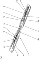
- the binding plate 1 shown in the drawing figures is intended to be mounted in the binding mounting portion of a ski, not shown, on the top and is used for arranging not shown ski binding parts, in particular a toe and a heel holder of a safety ski binding, which conventional manner may be performed.
- the binding plate 1 consists of several components, to which a base plate 2, in particular made of plastic as an injection molded part, a cover plate 3 likewise made of plastic as an injection molded part and two, in particular, metallic strip-shaped elements 4 belong.
- the over the entire length of the binding plate 1 extending base plate 2 has a rear mounting portion 5 for arranging the rear ski binding portion and a front mounting portion 6 for arranging the front ski binding portion.
- the lateral longitudinal edges of the base plate 2 are formed such that they each form a pair of slide rails 7 and 8, which each extend parallel to each other and from the respective end of the base plate 2 from pushing each one of the ski binding parts, which accordingly opposite to the slide rails 7, 8 shaped parts - support plates, housing parts or the like - have allowed.
- the base plate 2 is waisted in its middle portion extending between the rear and front mounting portions 5, 6, but the base plate 2 may also have an at least substantially constant width throughout.
- a flat elongated recess 9 is formed, which extends into the two mounting portions 5, 6 inside.
- the 4 shows is in the base plate 2 in the region of the recess 9, in each case in front of the mounting portions 5, 6, each an opening 10a, 10b formed.
- the two openings 10a, 10b are separated from each other by a bridge 12 of the base plate 2.
- the recess 9 has in the mounting areas 5, 6 symmetrical to the longitudinal axis of the base plate 2 broadening, in each of which an attachment point, in particular a respective attachment hole 15 is formed.
- Another pair of fixing holes 15 are located in the front end portion of the base plate 2. Of the four pairs of fixing holes 15, three are elongated in the longitudinal direction of the plate 2.
- the mounting holes 15 are used for screwing the base plate 2 to a ski, not shown, wherein the plate 2 is screwed fixed position on a pair of holes, the other pairs of holes 15 allow a certain relative movement of the base plate 2 in the ski longitudinal direction.
- each mounting area 5, 6 are formed in the base plate 2, on its central longitudinal axis, two slot-like fastening holes 11, wherein the measures provided for in the front mounting area 5 and the rear mounting area 6 two Holes 11 are spaced apart from each other in the order of the Leksverstell Kunststoffes the ski binding parts.
- the recess 17a is bounded by two parallel to the longitudinal axis of the base plate 2 extending lateral edges 18a, protrude from each of which three locking projections 19 which extend transversely to the longitudinal plate axis.
- the latching projections 19 are preferably equally spaced from each other and form between them, the transverse web 16 and a boundary edge of the recess 17a locking recesses 20.
- the second recess 17b is made shorter in the longitudinal direction of the plate 17a, their lateral edges 18b and the subsequent thereto lateral Longitudinal edges of the opening 10b are provided analogously with latching projections 19 and locking recesses 20.
- the two band-shaped elements 4 are designed to match.
- Each band-shaped element 4 has at its one end a portion with a series of latching points 25, which are formed in the illustrated embodiment as mutually parallel elevations, which are oriented transversely to the longitudinal extent of the band-shaped elements 4 and equally spaced.
- the latching points 25 may be formed as depressions.
- the rest stops 25 can, as in Fig. 6 shown to be formed on a separate latching plate 27 which is fixedly connected to the band-shaped element 4, for example riveted, is.
- the second end portion of the band-shaped element 4 is designed as a latching portion 26 with two rows of latching projections 26a at its longitudinal edges, which are designed such that they are positively inserted into the locking recesses 20 on the underside of the base plate 2.
- the band-shaped element 4 has a slightly inclined portion 4a, so that the latching portion 26 is offset from the portion with the latching plate 27 slightly in the level.
- cover plate 3 has a shape substantially adapted to the recess 9 of the base plate 2 shape or outer contour.
- the cover plate 3 is provided with holes or openings 22, so that in the binding plate 1 mounted on the ski, the screws inserted into the holes 15 are accessible when the cover plate 3 is positioned.
- the cover plate 3 has at its two end portions also two elongated and extending in the direction of their longitudinal recesses 23a, 23b, so that when mounted cover plate 3, the locking points 25 of the two band-shaped elements 4 remain accessible from above.
- the base plate 2, the cover plate 3 and the two band-shaped elements 4 are joined to the binding plate 1 by the two band-shaped elements 4 are inserted from the bottom of the base plate 3 with their portions carrying the advice points 25 through the openings 10 a and 10 b. Subsequently, the latching portions 26 of the two band-shaped elements 4 in the locking recesses 20 on the underside of the base plate 2 and at the same time the lugs 28 in the receiving openings 11 a, 11 b of the base plate 2 are locked.
- the slot-like design receiving openings 11 allow a relative movement between the elements 4 and the base plate 2 in the longitudinal direction thereof.
- the cover plate 3 is locked by means not shown snap elements in openings of the base plate 1.
- the front jaw of the front end of the binding plate 1 and the heel holder is pushed from the rear end of the binding plate 1.
- the toe and the heel holder are locked in the desired positions on the latching points 25 of the elements 4. This is done for example by a latching of the toe and on the heel holder in a known manner movably arranged and running in a known manner locking levers or the like.
- Scales 30 on the cover plate 3 allow a corresponding longitudinal positioning of the ski binding parts on the binding plate. 1
- the invention is not limited to the illustrated embodiment.
- the latching portions of the band-shaped elements 4 can be made in other ways and locked in other ways with the base plate 2. It is also possible, instead of two band-shaped elements 4 to provide a continuous band, which may be provided with separate locking plate at its end portions. In a continuous band, no crosspiece is present on the underside of the base plate. Otherwise, the latching elements, which can be brought into engagement with one another in a form-fitting manner, can be designed and arranged analogously to the illustrated embodiment on the base plate and on the belt.
Landscapes
- Package Frames And Binding Bands (AREA)
Description
- Die Erfindung betrifft eine an der Oberseite eines Skis zu befestigende Bindungsplatte zum Anordnen einer zwei Skibindungsteile aufweisenden Skibindung, mit einer Basisplatte, welche einen vorderen Montagebereich mit Gleitschienen für den einen Skibindungsteil und einen rückwärtigen Montagebereich mit Gleitschienen für den zweiten Skibindungsteil aufweist, und mit zumindest einem bandförmigen, an der Basisplatte einrastbaren Element mit zumindest einem an der Oberseite der Basisplatte befindlichen Endabschnitt mit Raststellen zum Einrasten von komplementären Rastelementen eines Skibindungsteils in gegenüber dem bandförmigen Element unterschiedlichen Längspositionen.
- Eine Bindungsplatte der eingangs genannten Art ist beispielsweise aus der
EP-A-1 621 237 bekannt. Das bandförmige Element weist Endabschnitte mit jeweils einer Reihe von Raststellen auf, wobei an der einen Reihe von Raststellen der eine Skibindungsteil und an der zweiten Reihe von Raststellen der andere Skibindungsteil jeweils in unterschiedlichen Positionen verrastbar sind, sodass jeder Skibindungsteil in seiner Längsposition verstellt und in der gewählten Position fixiert werden kann. Das bandförmige Element weist an seinem einen Ende eine Steckeinrichtung, insbesondere zwei Steckklauen, auf, die vom Band nach unten ragen und in Aufnahmestellen der Basisplatte einhängbar sind. Ist das Band in der Basisplatte eingehängt verläuft es weitgehend frei an der Oberseite der Bindungsplatte, um bei montierten Skibindungsteilen eine gewisse Längsbeweglichkeit derselben bei Skidurchbiegung zu ermöglichen. Zur Montage der Skibindungsteile sind diese am Band einzufädeln, sodass beide Skibindungsteile nur vom freien Ende des Bandes aus montierbar sind. - Aus der
EP-A-1 800 716 ist eine Vorrichtung zur Montage einer zwei Skibindungsteile aufweisenden Sicherheitsskibindung auf einem Ski bekannt, welche Vorrichtung zwei in Skilängsrichtung voneinander beabstandete und mit dem Ski verbundene Platten mit Führungsprofilen zum gleitbeweglichen Anordnen der beiden Skibindungsteile aufweist. In den Platten sind in Längsrichtung verlaufende Vertiefungen ausgebildet, in welchen die Endabschnitte eines bandförmigen Elementes derart eingelegt sind, dass dieses Element mit seiner Unterseite und seinen Längsseiten an den Platten geführt und abgestützt ist. Das bandförmige Element weist an der Oberseite im Bereich seiner Endabschnitte jeweils eine Reihe von Rastelementen auf und wird vor der Montage der Skibindungsteile mittig skifest festgelegt. Die Rastelemente wirken mit komplementären Rastelementen an den Skibindungsteilen zusammen, um derart die Skibindungsteile zu fixieren und bei Bedarf gegenüber dem Band bzw. den Platten in Längsrichtung zu verstellen. - In
WO 2007/096245 A2 wird ebenfalls ein Verstellsystem, mit endlosem Band, offenbart. Der Erfindung liegt die Aufgabe zugrunde, eine Bindungsplatte der eingangs genannten Art derart auszuführen, dass sie bei einer einfachen Ausführung eine hohe Stabilität aufweist und dass die Skibindungsteile schnell und unproblematisch montierbar sind.
Gelöst wird die gestellte Aufgabe erfindungsgemäß dadurch, dass das bandförmige Element im mittleren Bereich der Basisplatte an der Unterseite der Basisplatte einrastbar ist und an der Oberseite der Basisplatte an zumindest einer weiteren Stelle auf längsbewegliche Weise, jedoch in seitlicher Richtung sowie gegen ein Abheben in vertikaler Richtung fixiert, an der Basisplatte gehalten ist. - Bei einer erfindungsgemäß ausgeführten Bindungsplatte ist das bzw. sind die bandförmige(n) Element(e) an der Unterseite der Basisplatte und somit gesichert und stabil eingerastet. Jeder Skibindungsteil kann seinem Montagebereich benachbart auf die Bindungsplatte geschoben werden und ohne dass ein Einfädeln in das Band erforderlich ist, da das Band/die Bänder zusätzlich an der Oberseite der Basisplatte gehalten ist bzw. sind. Die Montage der Skibindung geht daher schnell und problemlos vonstatten.
- Bei einer bevorzugten Ausführungsform der Erfindung sind zwei bandförmige Elemente vorgesehen, der aneinander zugewandte Endabschnitte an der Unterseite der Basisplatte einrastbar sind. Zwei bandförmige Elemente lassen sich an der Basisplatte einfacher positionieren als ein einzelnes, langes Band.
- Für die Übertragung der beim Skifahren auf die bandförmigen Elemente wirkenden Kräfte ist es ferner günstig, wenn diese in Längsrichtung der Basisplatte unter einem gegenseitigen Abstand an der Unterseite der Basisplatte eingerastet sind.
- Bei einer bevorzugten Ausführungsform der Erfindung kann zwischen den beiden Enden der bandförmigen Elemente ein Quersteg ausgebildet sein, welcher in der verrasteten Lage mit den Enden der bandförmigen Elemente in Kontakt kommt. Auf diese Weise lassen sich Stoßbelastungen in Längsrichtung der Bindungsplatte von den bandförmigen Elemente auf die Basisplatte besonders gut übertragen.
- Grundsätzlich kann das bzw. können die bandförmige(n) Element(e) an der Unterseite der Bindungsplatte auf beliebige Weise formschlüssig einrastbar sein. Formschlüssige Verbindungen lassen sich beim Zusammenbau der Bindungsplatte besonders schnell herstellen.
- Sind nun die den Formschluss bewirkenden Rastelemente des bzw. der bandförmigen Elemente(s) und der Basisplatte quer bzw. senkrecht zur Längsrichtung der Basisplatte orientiert, ist die Kraftübertragung bei Stoßbelastungen optimal.
- Zum Ausgleich des Niveauunterschiedes zwischen den an der Ober- und an der Unterseite der Basisplatte positionierten Abschnitte sind am bandförmigen Element bzw. an den bandförmigen Elementen gegenüber der Basisplatte schräg verlaufende Abschnitte vorgesehen.
- Da die beim Skifahren auftretenden Belastungen und Kräfte zu einem erheblichen Teil von den Skibindungsbacken auf das bzw. die bandförmige(n) Element(e) übertragen werden, ist es vorteilhaft, das bzw. die bandförmige(n) Element(e) zusätzlich an seinem/ihren plattenäußeren Enden auf längsbewegliche Weise zu halten, wobei eine Fixierung in seitlicher Richtung sowie gegen ein Abheben in vertikaler Richtung auch an diesen Befestigungsstellen gewährleistet sein soll.
- Es vereinfacht die Herstellung des bzw. der bandförmigen Elemente(s), wenn die mit den Einraststellen versehenen Abschnitte auf separaten Plättchen ausgebildet sind, welche mit den/dem bandförmigen Element(en) fest verbunden sind.
- An der Oberseite der Basisplatte kann eine Abdeckplatte, auf einfache Weise mittels Schnappelementen, befestigt sein. Die Abdeckplatte braucht im Wesentlichen lediglich im Bereich der die Einraststellen versehenen Endabschnitte des bzw. der bandförmigen Elemente(s) ausgenommen zu sein.
- Die Erfindung betrifft ferner einen Ski, auf welchem eine erfindungsgemäß ausgeführte Bindungsplatte befestigt ist oder in/auf welchen eine derartige Bindungsplatte bei der Herstellung des Skis, insbesondere in an sich bekannter Weise, integriert worden ist.
- Weitere Merkmale, Vorteile und Einzelheiten der Erfindung werden nun anhand der Zeichnung, die schematisch ein Ausführungsbeispiel darstellt, näher beschrieben. Dabei zeigen
-
Fig. 1 eine Ansicht der Oberseite einer Bindungsplatte, -
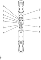
Fig. 2 eine Ansicht der Unterseite der Bindungsplatte, -
Fig. 3 eine Ansicht einer Basisplatte, -
Fig. 4 undFig. 5 Ansichten der Ober- und der Unterseite der Basisplatte und -
Fig. 6 eine Ansicht eines bandförmigen Elementes. - Die in den Zeichnungsfiguren gezeigte Bindungsplatte 1 ist dafür vorgesehen, im Bindungsmontagebereich eines nicht gezeigten Skis auf dessen Oberseite befestigt zu werden und dient zum Anordnen von nicht gezeigten Skibindungsteilen, insbesondere einem Vorderbacken und einem Fersenhalter einer Sicherheitsskibindung, welche auf herkömmliche Weise ausgeführt sein kann. Die Bindungsplatte 1 besteht aus mehreren Bestandteilen, zu welchen eine insbesondere als Spritzgussteil aus Kunststoff gefertigte Basisplatte 2, eine ebenfalls als Spritzgussteil aus Kunststoff hergestellte Abdeckplatte 3 und zwei insbesondere metallische bandförmige Elemente 4 gehören. Die über die gesamte Länge der Bindungsplatte 1 verlaufende Basisplatte 2 weist einen rückwärtigen Montagebereich 5 zum Anordnen des rückwärtigen Skibindungsteils und einen vorderen Montagebereich 6 zum Anordnen des vorderen Skibindungsteils auf. In den Montagebereichen 5, 6 sind die seitlichen Längskanten der Basisplatte 2 derart geformt, dass sie je ein Paar von Gleitschienen 7 und 8 bilden, welche jeweils parallel zueinander verlaufen und vom jeweiligen Ende der Basisplatte 2 aus ein Aufschieben je eines der Skibindungsteile, welche entsprechend gegengleich zu den Gleitschienen 7, 8 geformte Teile - Tragplatten, Gehäuseteile oder dergleichen - aufweisen, gestatten. Bei der gezeigten Ausführung ist die Basisplatte 2 in ihrem mittleren Abschnitt, welcher sich zwischen dem rückwärtigen und dem vorderen Montagebereich 5, 6 erstreckt, tailliert ausgeführt, die Basisplatte 2 kann jedoch auch durchgehend eine zumindest im Wesentlichen konstante Breite aufweisen. An der Oberseite der Basisplatte 2 ist eine flache langgestreckte Vertiefung 9 ausgeformt, welche sich in die beiden Montagebereiche 5, 6 hinein erstreckt. Wie insbesondere
Fig. 4 zeigt ist in der Basisplatte 2 im Bereich der Ausnehmung 9, jeweils vor den Montagebereichen 5, 6, je eine Öffnung 10a, 10b ausgebildet. Die beiden Öffnungen 10a, 10b sind voneinander durch eine Brücke 12 der Basisplatte 2 getrennt. Die Vertiefung 9 weist in den Montagebereichen 5, 6 symmetrisch zur Längsachse der Basisplatte 2 Verbreiterungen auf, in welchen jeweils eine Befestigungsstelle, insbesondere je ein Befestigungsloch 15, ausgebildet ist. Ein weiteres Paar von Befestigungslöchern 15 befindet sich im vorderen Endabschnitt der Basisplatte 2. Von den vier Paaren von Befestigungslöchern 15 sind drei in Längsrichtung der Platte 2 langlochartig ausgeführt. Die Befestigungslöcher 15 dienen zum Anschrauben der Basisplatte 2 an einem nicht gezeigten Ski, wobei die Platte 2 an einem Lochpaar positionsfest angeschraubt wird, die weiteren Paare von Löchern 15 gestatten eine gewisse Relativbewegung der Basisplatte 2 in Skilängsrichtung. - In jedem Montagebereich 5, 6 sind in der Basisplatte 2, auf ihrer Mittellängsachse, zwei langlochartig ausgeführte Befestigungslöcher 11 ausgebildet, wobei die im vorderen Montagebereich 5 und die im rückwärtigen Montagebereich 6 vorgesehenen beiden Löcher 11 voneinander in der Größenordnung des Längsverstellbereiches der Skibindungsteile beabstandet sind.
- An der Unterseite der Basisplatte 2 befindet sich unterhalb der Brücke 12 ein schmaler, im rechten Winkel zur Längsachse der Basisplatte 2 verlaufender, vorspringender Quersteg 16, welcher flache Ausnehmungen 17a, 17b begrenzt. Die Ausnehmung 17a ist durch zwei parallel zur Längsachse der Basisplatte 2 verlaufende seitliche Kanten 18a begrenzt, von welchen jeweils drei Rastvorsprünge 19 abragen, die sich quer zur Plattenlängsachse erstrecken. Die Rastvorsprünge 19 sind voneinander bevorzugt gleich beabstandet und bilden zwischen sich, zum Quersteg 16 und zu einer Begrenzungskante der Ausnehmung 17a Rastvertiefungen 20. Die zweite Ausnehmung 17b ist in Plattenlängsrichtung kürzer ausgeführt als die Ausnehmung 17a, ihre seitlichen Kanten 18b sowie die an diese anschließenden seitlichen Längskanten der Öffnung 10b sind analog mit Rastvorsprüngen 19 und Rastvertiefungen 20 versehen.
- Die beiden bandförmigen Elemente 4 sind übereinstimmend ausgeführt. Jedes bandförmige Element 4 weist an seinem einen Ende einen Abschnitt mit einer Reihe von Raststellen 25 auf, welche bei dargestellten Ausführungsform als parallel zueinander verlaufende Erhebungen ausgebildet sind, die quer zur Längserstreckung der bandförmigen Elemente 4 orientiert und voneinander gleich beabstandet sind. Alternativ dazu können die Raststellen 25 als Vertiefungen ausgebildet sein. Die Raststellen 25 können, wie in
Fig. 6 gezeigt, an einem gesonderten Rastplättchen 27 ausgebildet sein, welches mit dem bandförmigen Element 4 fest verbunden, beispielsweise vernietet, ist. Der zweite Endabschnitt des bandförmigen Elementes 4 ist als Rastabschnitt 26 mit zwei Reihen von Rastvorsprüngen 26a an seinen in Längsrichtung verlaufenden Kanten ausgeführt, welche derart ausgestaltet sind, dass sie formschlüssig in die Rastvertiefungen 20 an der Unterseite der Basisplatte 2 einsetzbar sind. Zwischen den Raststellen 25 und dem Rastabschnitt 26 weist das bandförmige Element 4 einen leicht geneigt verlaufenden Abschnitt 4a auf, sodass der Rastabschnitt 26 gegenüber dem Abschnitt mit dem Rastplättchen 27 geringfügig im Niveau versetzt ist. - Von der Unterseite der bandförmigen Elemente 4 ragen jeweils zwei Ansatznieten 28 ab, welche jeweils vor und hinter der Reihe von Einraststellen 25 am bandförmigen Element 4 befestigt sind und einen zylindrischen Fußabschnitt 28a aufweisen, welcher einen scheibenförmigen Kopf 28b trägt.
- Die in
Fig. 1 gezeigte Abdeckplatte 3 weist eine im Wesentlichen an die Ausnehmung 9 der Basisplatte 2 angepasste Form bzw. Außenkontur auf. Im Bereich der Befestigungslöcher 15 ist die Abdeckplatte 3 mit Löchern bzw. Öffnungen 22 versehen, sodass bei am Ski montierter Bindungsplatte 1 die in die Löcher 15 eingesetzten Schrauben bei positionierter Abdeckplatte 3 zugänglich sind. Die Abdeckplatte 3 weist an ihren beiden Endabschnitten ferner zwei lang gestreckte und in Richtung ihrer Längserstreckung verlaufende Aussparungen 23a, 23b auf, sodass bei montierter Abdeckplatte 3 die Raststellen 25 der beiden bandförmigen Elemente 4 von oben zugänglich bleiben. - Die Basisplatte 2, die Abdeckplatte 3 und die beiden bandförmigen Elemente 4 werden zur Bindungsplatte 1 zusammengefügt, indem die beiden bandförmigen Elemente 4 von der Unterseite der Basisplatte 3 mit ihren die Ratstellen 25 tragenden Abschnitten durch die Öffnungen 10a bzw. 10b gesteckt werden. Anschließend werden die Rastabschnitte 26 der beiden bandförmigen Elemente 4 in den Rastvertiefungen 20 an der Unterseite der Basisplatte 2 und gleichzeitig die Ansatznieten 28 in den Aufnahmeöffnungen 11a, 11 b der Basisplatte 2 verrastet. Die langlochartig ausgeführten Aufnahmeöffnungen 11 gestatten eine Relativbewegung zwischen den Elementen 4 und der Basisplatte 2 in Längsrichtung derselben. Die Abdeckplatte 3 wird mittels nicht gezeigter Schnappelemente in Öffnungen der Basisplatte 1 eingerastet. Zur Montage der nicht gezeigten Skibindung wird deren Vorderbacken vom vorderen Ende der Bindungsplatte 1 und deren Fersenhalter vom rückwärtigen Ende der Bindungsplatte 1 aufgeschoben. Der Vorderbacken und der Fersenhalter werden in den gewünschten Positionen an den Raststellen 25 der Elemente 4 verrastet. Dies erfolgt beispielsweise durch ein Einrasten von am Vorderbacken und am Fersenhalter in bekannter Weise bewegbar angeordneten und in bekannter Weise ausgeführten Rasthebeln oder dergleichen. Skalen 30 auf der Abdeckplatte 3 erlauben eine entsprechende Längspositionierung der Skibindungsteile auf der Bindungsplatte 1.
- Die Erfindung ist auf die dargestellte Ausführungsform nicht eingeschränkt. So können beispielsweise die Rastabschnitte der bandförmigen Elemente 4 auf andere Weise ausgeführt und auf andere Weise mit der Basisplatte 2 verrastet werden. Es ist ferner möglich, anstelle von zwei bandförmigen Elementen 4 ein durchgehendes Band vorzusehen, welches mit gesonderten Rastplättchen an seinen Endabschnitten versehen sein kann. Bei einem durchgehenden Band ist an der Unterseite der Basisplatte kein Quersteg vorhanden. Ansonst können die miteinander formschlüssig in Eingriff bringbaren Rastelemente an der Basisplatte und am Band analog zur dargestellten Ausführungsform ausgeführt und angeordnet sein.
-
- 1 ..........
- Bindungsplatte
- 2 ..........
- Basisplatte
- 3 ..........
- Abdeckplatte
- 4 ..........
- bandförmiges Element
- 4a ........
- geneigter Abschnitt
- 5 ..........
- rückwärtiger Montagebereich
- 6 ..........
- vorderer Montagebereich
- 7 ..........
- Gleitschiene
- 8 ..........
- Gleitschiene
- 9 ..........
- Ausnehmung
- 10a ......
- Öffnung
- 10b ......
- Öffnung
- 11 ........
- Befestigungsloch
- 12 ........
- Brücke
- 14 ........
- Verbreiterung
- 15........
- Befestigungsloch
- 16 ........
- Quersteg
- 17a ......
- Ausnehmung
- 17b ......
- Ausnehmung
- 18a ......
- Kante
- 18b ......
- Kante
- 19 ........
- Rastvorsprung
- 20 ........
- Rastvertiefung
- 23a ......
- Aussparung
- 23b ......
- Aussparung
- 25 ........
- Raststellen
- 26 ........
- Rastabschnitt
- 26a ......
- Rastvorsprung
- 27 ........
- Rastplättchen
- 28 ........
- Ansatzniet
- 28a ......
- Fußabschnitt
- 28b ......
- Kopf
- 30 ........
- Skala
Claims (12)
- An der Oberseite eines Skis zu befestigende Bindungsplatte zum Anordnen einer zwei Skibindungsteile aufweisenden Skibindung, mit einer Basisplatte (2), welche einen vorderen Montagebereich (5) mit Gleitschienen (7) für den einen Skibindungsteil und einen rückwärtigen Montagebereich (6) mit Gleitschienen (8) für den zweiten Skibindungsteil aufweist, und mit zumindest einem bandförmigen, an der Basisplatte (2) einrastbaren Element (4) dadurch gekennzeichnet, dass das bandförmige Element (4) zumindest einen an der Oberseite der Basisplatte (2) befindlichen Endabschnitt mit Raststellen (25) zum Einrasten von komplementären Rastelementen eines Skibindungsteils in gegenüber dem bandförmigen Element (4) unterschiedlichen Längspositionen besitzt, wobei das bandförmige Element (4) im mittleren Bereich der Basisplatte (2) an der Unterseite der Basisplatte (2) einrastbar ist und an der Oberseite der Basisplatte (2) zumindest an einer weiteren Stelle auf längsbewegliche Weise, jedoch in seitlicher Richtung sowie gegen ein Abheben in vertikaler Richtung fixiert, an der Basisplatte (2) gehalten ist.
- Bindungsplatte (1) nach Anspruch 1, dadurch gekennzeichnet, dass zwei bandförmige Elemente (4) vorgesehen sind, deren einander zugewandte Endabschnitte an der Unterseite der Basisplatte (2) einrastbar sind.
- Bindungsplatte (1) nach Anspruch 1 oder 2, dadurch gekennzeichnet, dass die beiden bandförmigen Elemente (4) in Längsrichtung der Basisplatte (2) unter einem gegenseitigen Abstand an der Unterseite der Basisplatte (2) einrastbar sind.
- Bindungsplatte (1) nach Anspruch 2 oder 3, dadurch gekennzeichnet, dass zwischen den verrasteten Endabschnitten der beiden bandförmigen Elemente (4) in der Basisplatte (2) ein mit den Enden der bandförmigen Elemente (4) in Kontakt stehender Quersteg (14) ausgebildet ist.
- Bindungsplatte (1) nach einem der Ansprüche 1 bis 3, dadurch gekennzeichnet, dass das bzw. die bandförmige(n) Element(e) (4) an der Unterseite der Bindungsplatte (2) formschlüssig einrastbar ist bzw. sind.
- Bindungsplatte (1) nach Anspruch 5, dadurch gekennzeichnet, dass die den Formschluss bewirkenden Rastelemente des bzw. der bandförmigen Element(e)s (4) quer zur Längsrichtung der Basisplatte (2) orientiert sind.
- Bindungsplatte (1) nach einem der Ansprüche 1 bis 4, dadurch gekennzeichnet, dass das bandförmige Element (4) zum Niveauausgleich zwischen der Ober- und Unterseite der Basisplatte (2) einen gegenüber der Basisplatte (2) schräg verlaufenden Abschnitt (4a) aufweist.
- Bindungsplatte (1) nach einem der Ansprüche 1 bis 6, dadurch gekennzeichnet, dass das bzw. die bandförmigen Element(e) (4) auch an seinem/ihren plattenäußeren Enden auf längsbewegliche Weise, in seitlicher Richtung sowie gegen ein Abheben in vertikaler Richtung fixiert, an der Basisplatte (2) gehalten ist bzw. sind.
- Bindungsplatte (1) nach einem der Ansprüche 1 bis 7, dadurch gekennzeichnet, dass die mit den Einraststellen (25) versehene Abschnitte auf separaten Plättchen ausgebildet sind, welche mit dem/den bandförmigen Element(en) (4) fest verbunden sind.
- Bindungsplatte (1) nach einem der Ansprüche 1 bis 6, dadurch gekennzeichnet, dass an der Oberseite der Basisplatte (2) eine Abdeckplatte (3) mittels Schnappelementen befestigt ist.
- Ski, auf welchem eine Bindungsplatte (1) nach Anspruch 1 und nach einem oder mehreren der Ansprüche 2 bis 9 befestigt ist.
- Ski, in welchen eine Bindungsplatte (1) nach Anspruch 1 und nach einem oder mehreren der Ansprüche 2 bis 9 integriert ist.
Applications Claiming Priority (1)
| Application Number | Priority Date | Filing Date | Title |
|---|---|---|---|
| AT0189509A AT508892B1 (de) | 2009-11-30 | 2009-11-30 | Bindungsplatte und ski mit einer bindungsplatte |
Publications (2)
| Publication Number | Publication Date |
|---|---|
| EP2327458A1 EP2327458A1 (de) | 2011-06-01 |
| EP2327458B1 true EP2327458B1 (de) | 2016-04-06 |
Family
ID=43708958
Family Applications (1)
| Application Number | Title | Priority Date | Filing Date |
|---|---|---|---|
| EP10191832.4A Active EP2327458B1 (de) | 2009-11-30 | 2010-11-19 | Bindungsplatte und Ski mit einer Bindungsplatte |
Country Status (2)
| Country | Link |
|---|---|
| EP (1) | EP2327458B1 (de) |
| AT (1) | AT508892B1 (de) |
Families Citing this family (2)
| Publication number | Priority date | Publication date | Assignee | Title |
|---|---|---|---|---|
| CH718467A2 (de) | 2021-03-22 | 2022-09-30 | Duss Roland | Skibindungsplatte 2.0. |
| EP4094813A1 (de) | 2021-05-28 | 2022-11-30 | Duss Evolution GmbH | Bindungsplatte |
Family Cites Families (5)
| Publication number | Priority date | Publication date | Assignee | Title |
|---|---|---|---|---|
| FR2873592B1 (fr) | 2004-07-30 | 2006-12-01 | Salomon Sa | Ensemble de retenue d'une chaussure sur une planche de glisse |
| DE102004048768A1 (de) * | 2004-10-05 | 2006-04-06 | Marker Deutschland Gmbh | Verstellanordnung einer Ski- bzw. Snowboardbindung |
| AT9190U1 (de) | 2005-12-21 | 2007-06-15 | Tyrolia Technology Gmbh | Vorrichtung zur montage einer skibindung |
| ITPN20060006A1 (it) * | 2006-01-27 | 2007-07-28 | Nordica Spa | Procedimento per la realizzazione di un attrezzo sportivo, e attrezzo sportivo ottenuto con tale procedimento. |
| ITPN20060005U1 (it) * | 2006-02-20 | 2007-08-21 | Tecnologica S P A | Piastra di attacco perfezionata di uno scarpone ad uno sci. |
-
2009
- 2009-11-30 AT AT0189509A patent/AT508892B1/de not_active IP Right Cessation
-
2010
- 2010-11-19 EP EP10191832.4A patent/EP2327458B1/de active Active
Also Published As
| Publication number | Publication date |
|---|---|
| AT508892B1 (de) | 2011-05-15 |
| AT508892A4 (de) | 2011-05-15 |
| EP2327458A1 (de) | 2011-06-01 |
Similar Documents
| Publication | Publication Date | Title |
|---|---|---|
| DE3927875A1 (de) | Sicherheitsskibindung | |
| DE2736079A1 (de) | Einrastbare reihenklemme oder anschlussmoduln sowie traegerschiene hierfuer | |
| EP3526490B2 (de) | Kettenglied für eine energieführungskette | |
| AT508892B1 (de) | Bindungsplatte und ski mit einer bindungsplatte | |
| AT502276A2 (de) | Kupplungsvorrichtung | |
| DE3929352A1 (de) | Seitliche fuehrungsvorrichtung eines skischuhs | |
| DE4313242C2 (de) | Kettenglied für eine Energieführungskette | |
| EP1600196B1 (de) | Einrichtung bestehend aus zumindest einer Bindungsplatte | |
| EP1764138B1 (de) | Vorrichtung zum Positionieren einer zwei Skibindungsteile aufweisenden Skibindung auf einem Ski | |
| EP1366785A1 (de) | Ski, Verfahren zur Montage einer Skibindung an dem Ski und Verfahren zur Herstellung des Skis | |
| EP1669112B1 (de) | Bindungssystem für Skier | |
| AT400680B (de) | Sicherheitsskibindung | |
| EP1800716B1 (de) | Vorrichtung zur Montage einer Skibindung | |
| EP4385588B1 (de) | Ausgleichselement und fersenbacken mit einem ausgleichselement | |
| EP1442769B1 (de) | Anordnung zur Montage einer Skibindung, eines Skibindungsteils oder eines diese bzw. dieses tragendes, insbesondere plattenförmigen Teils, an einem Ski | |
| DE102006059180B4 (de) | Montagesystem für schienenmontable Gehäuse | |
| EP2620188B1 (de) | Skibindung zum Tourengehen | |
| EP1247551B1 (de) | Schibindung | |
| AT400404B (de) | Haltevorrichtung für eine skibindung | |
| DE202004004304U1 (de) | Gleitbrett, insbesondere Ski | |
| EP2556865B1 (de) | Harscheisen | |
| AT507889B1 (de) | Skibindung | |
| EP1502629A1 (de) | Verfahren und Anordnung zum Positionieren einer Skibindung auf einem Ski | |
| DE202007000292U1 (de) | Verstelleinrichtung | |
| DE202004012590U1 (de) | Fersenabstützvorrichtung für einen Skischuh |
Legal Events
| Date | Code | Title | Description |
|---|---|---|---|
| PUAI | Public reference made under article 153(3) epc to a published international application that has entered the european phase |
Free format text: ORIGINAL CODE: 0009012 |
|
| AK | Designated contracting states |
Kind code of ref document: A1 Designated state(s): AL AT BE BG CH CY CZ DE DK EE ES FI FR GB GR HR HU IE IS IT LI LT LU LV MC MK MT NL NO PL PT RO RS SE SI SK SM TR |
|
| AX | Request for extension of the european patent |
Extension state: BA ME |
|
| 17P | Request for examination filed |
Effective date: 20110630 |
|
| RIC1 | Information provided on ipc code assigned before grant |
Ipc: A63C 9/00 20120101AFI20150903BHEP |
|
| GRAP | Despatch of communication of intention to grant a patent |
Free format text: ORIGINAL CODE: EPIDOSNIGR1 |
|
| INTG | Intention to grant announced |
Effective date: 20151020 |
|
| RIN1 | Information on inventor provided before grant (corrected) |
Inventor name: HOESL, ERWIN Inventor name: PFALLER, ROBERT Inventor name: JAHNEL, GERNOT Inventor name: BAUMGARTNER, MANFRED |
|
| GRAS | Grant fee paid |
Free format text: ORIGINAL CODE: EPIDOSNIGR3 |
|
| GRAA | (expected) grant |
Free format text: ORIGINAL CODE: 0009210 |
|
| AK | Designated contracting states |
Kind code of ref document: B1 Designated state(s): AL AT BE BG CH CY CZ DE DK EE ES FI FR GB GR HR HU IE IS IT LI LT LU LV MC MK MT NL NO PL PT RO RS SE SI SK SM TR |
|
| REG | Reference to a national code |
Ref country code: GB Ref legal event code: FG4D Free format text: NOT ENGLISH |
|
| REG | Reference to a national code |
Ref country code: AT Ref legal event code: REF Ref document number: 787100 Country of ref document: AT Kind code of ref document: T Effective date: 20160415 Ref country code: CH Ref legal event code: EP |
|
| REG | Reference to a national code |
Ref country code: IE Ref legal event code: FG4D Free format text: LANGUAGE OF EP DOCUMENT: GERMAN |
|
| REG | Reference to a national code |
Ref country code: DE Ref legal event code: R096 Ref document number: 502010011389 Country of ref document: DE |
|
| REG | Reference to a national code |
Ref country code: LT Ref legal event code: MG4D Ref country code: NL Ref legal event code: MP Effective date: 20160406 |
|
| PG25 | Lapsed in a contracting state [announced via postgrant information from national office to epo] |
Ref country code: NL Free format text: LAPSE BECAUSE OF FAILURE TO SUBMIT A TRANSLATION OF THE DESCRIPTION OR TO PAY THE FEE WITHIN THE PRESCRIBED TIME-LIMIT Effective date: 20160406 |
|
| PG25 | Lapsed in a contracting state [announced via postgrant information from national office to epo] |
Ref country code: LT Free format text: LAPSE BECAUSE OF FAILURE TO SUBMIT A TRANSLATION OF THE DESCRIPTION OR TO PAY THE FEE WITHIN THE PRESCRIBED TIME-LIMIT Effective date: 20160406 Ref country code: PL Free format text: LAPSE BECAUSE OF FAILURE TO SUBMIT A TRANSLATION OF THE DESCRIPTION OR TO PAY THE FEE WITHIN THE PRESCRIBED TIME-LIMIT Effective date: 20160406 Ref country code: NO Free format text: LAPSE BECAUSE OF FAILURE TO SUBMIT A TRANSLATION OF THE DESCRIPTION OR TO PAY THE FEE WITHIN THE PRESCRIBED TIME-LIMIT Effective date: 20160706 Ref country code: FI Free format text: LAPSE BECAUSE OF FAILURE TO SUBMIT A TRANSLATION OF THE DESCRIPTION OR TO PAY THE FEE WITHIN THE PRESCRIBED TIME-LIMIT Effective date: 20160406 Ref country code: IS Free format text: LAPSE BECAUSE OF FAILURE TO SUBMIT A TRANSLATION OF THE DESCRIPTION OR TO PAY THE FEE WITHIN THE PRESCRIBED TIME-LIMIT Effective date: 20160806 |
|
| REG | Reference to a national code |
Ref country code: FR Ref legal event code: PLFP Year of fee payment: 7 |
|
| PG25 | Lapsed in a contracting state [announced via postgrant information from national office to epo] |
Ref country code: PT Free format text: LAPSE BECAUSE OF FAILURE TO SUBMIT A TRANSLATION OF THE DESCRIPTION OR TO PAY THE FEE WITHIN THE PRESCRIBED TIME-LIMIT Effective date: 20160808 Ref country code: SE Free format text: LAPSE BECAUSE OF FAILURE TO SUBMIT A TRANSLATION OF THE DESCRIPTION OR TO PAY THE FEE WITHIN THE PRESCRIBED TIME-LIMIT Effective date: 20160406 Ref country code: GR Free format text: LAPSE BECAUSE OF FAILURE TO SUBMIT A TRANSLATION OF THE DESCRIPTION OR TO PAY THE FEE WITHIN THE PRESCRIBED TIME-LIMIT Effective date: 20160707 Ref country code: ES Free format text: LAPSE BECAUSE OF FAILURE TO SUBMIT A TRANSLATION OF THE DESCRIPTION OR TO PAY THE FEE WITHIN THE PRESCRIBED TIME-LIMIT Effective date: 20160406 Ref country code: RS Free format text: LAPSE BECAUSE OF FAILURE TO SUBMIT A TRANSLATION OF THE DESCRIPTION OR TO PAY THE FEE WITHIN THE PRESCRIBED TIME-LIMIT Effective date: 20160406 Ref country code: HR Free format text: LAPSE BECAUSE OF FAILURE TO SUBMIT A TRANSLATION OF THE DESCRIPTION OR TO PAY THE FEE WITHIN THE PRESCRIBED TIME-LIMIT Effective date: 20160406 Ref country code: LV Free format text: LAPSE BECAUSE OF FAILURE TO SUBMIT A TRANSLATION OF THE DESCRIPTION OR TO PAY THE FEE WITHIN THE PRESCRIBED TIME-LIMIT Effective date: 20160406 |
|
| PG25 | Lapsed in a contracting state [announced via postgrant information from national office to epo] |
Ref country code: IT Free format text: LAPSE BECAUSE OF FAILURE TO SUBMIT A TRANSLATION OF THE DESCRIPTION OR TO PAY THE FEE WITHIN THE PRESCRIBED TIME-LIMIT Effective date: 20160406 |
|
| REG | Reference to a national code |
Ref country code: DE Ref legal event code: R097 Ref document number: 502010011389 Country of ref document: DE |
|
| PG25 | Lapsed in a contracting state [announced via postgrant information from national office to epo] |
Ref country code: RO Free format text: LAPSE BECAUSE OF FAILURE TO SUBMIT A TRANSLATION OF THE DESCRIPTION OR TO PAY THE FEE WITHIN THE PRESCRIBED TIME-LIMIT Effective date: 20160406 Ref country code: CZ Free format text: LAPSE BECAUSE OF FAILURE TO SUBMIT A TRANSLATION OF THE DESCRIPTION OR TO PAY THE FEE WITHIN THE PRESCRIBED TIME-LIMIT Effective date: 20160406 Ref country code: SK Free format text: LAPSE BECAUSE OF FAILURE TO SUBMIT A TRANSLATION OF THE DESCRIPTION OR TO PAY THE FEE WITHIN THE PRESCRIBED TIME-LIMIT Effective date: 20160406 Ref country code: DK Free format text: LAPSE BECAUSE OF FAILURE TO SUBMIT A TRANSLATION OF THE DESCRIPTION OR TO PAY THE FEE WITHIN THE PRESCRIBED TIME-LIMIT Effective date: 20160406 Ref country code: EE Free format text: LAPSE BECAUSE OF FAILURE TO SUBMIT A TRANSLATION OF THE DESCRIPTION OR TO PAY THE FEE WITHIN THE PRESCRIBED TIME-LIMIT Effective date: 20160406 |
|
| PLBE | No opposition filed within time limit |
Free format text: ORIGINAL CODE: 0009261 |
|
| STAA | Information on the status of an ep patent application or granted ep patent |
Free format text: STATUS: NO OPPOSITION FILED WITHIN TIME LIMIT |
|
| PG25 | Lapsed in a contracting state [announced via postgrant information from national office to epo] |
Ref country code: BE Free format text: LAPSE BECAUSE OF NON-PAYMENT OF DUE FEES Effective date: 20161130 Ref country code: SM Free format text: LAPSE BECAUSE OF FAILURE TO SUBMIT A TRANSLATION OF THE DESCRIPTION OR TO PAY THE FEE WITHIN THE PRESCRIBED TIME-LIMIT Effective date: 20160406 |
|
| 26N | No opposition filed |
Effective date: 20170110 |
|
| PG25 | Lapsed in a contracting state [announced via postgrant information from national office to epo] |
Ref country code: SI Free format text: LAPSE BECAUSE OF FAILURE TO SUBMIT A TRANSLATION OF THE DESCRIPTION OR TO PAY THE FEE WITHIN THE PRESCRIBED TIME-LIMIT Effective date: 20160406 |
|
| GBPC | Gb: european patent ceased through non-payment of renewal fee |
Effective date: 20161119 |
|
| REG | Reference to a national code |
Ref country code: IE Ref legal event code: MM4A |
|
| PG25 | Lapsed in a contracting state [announced via postgrant information from national office to epo] |
Ref country code: LU Free format text: LAPSE BECAUSE OF NON-PAYMENT OF DUE FEES Effective date: 20161130 |
|
| REG | Reference to a national code |
Ref country code: FR Ref legal event code: PLFP Year of fee payment: 8 |
|
| PG25 | Lapsed in a contracting state [announced via postgrant information from national office to epo] |
Ref country code: IE Free format text: LAPSE BECAUSE OF NON-PAYMENT OF DUE FEES Effective date: 20161119 Ref country code: GB Free format text: LAPSE BECAUSE OF NON-PAYMENT OF DUE FEES Effective date: 20161119 |
|
| REG | Reference to a national code |
Ref country code: BE Ref legal event code: MM Effective date: 20161130 |
|
| PG25 | Lapsed in a contracting state [announced via postgrant information from national office to epo] |
Ref country code: CY Free format text: LAPSE BECAUSE OF FAILURE TO SUBMIT A TRANSLATION OF THE DESCRIPTION OR TO PAY THE FEE WITHIN THE PRESCRIBED TIME-LIMIT Effective date: 20160406 Ref country code: HU Free format text: LAPSE BECAUSE OF FAILURE TO SUBMIT A TRANSLATION OF THE DESCRIPTION OR TO PAY THE FEE WITHIN THE PRESCRIBED TIME-LIMIT; INVALID AB INITIO Effective date: 20101119 |
|
| PG25 | Lapsed in a contracting state [announced via postgrant information from national office to epo] |
Ref country code: MK Free format text: LAPSE BECAUSE OF FAILURE TO SUBMIT A TRANSLATION OF THE DESCRIPTION OR TO PAY THE FEE WITHIN THE PRESCRIBED TIME-LIMIT Effective date: 20160406 Ref country code: MC Free format text: LAPSE BECAUSE OF FAILURE TO SUBMIT A TRANSLATION OF THE DESCRIPTION OR TO PAY THE FEE WITHIN THE PRESCRIBED TIME-LIMIT Effective date: 20160406 Ref country code: TR Free format text: LAPSE BECAUSE OF FAILURE TO SUBMIT A TRANSLATION OF THE DESCRIPTION OR TO PAY THE FEE WITHIN THE PRESCRIBED TIME-LIMIT Effective date: 20160406 |
|
| PG25 | Lapsed in a contracting state [announced via postgrant information from national office to epo] |
Ref country code: BG Free format text: LAPSE BECAUSE OF FAILURE TO SUBMIT A TRANSLATION OF THE DESCRIPTION OR TO PAY THE FEE WITHIN THE PRESCRIBED TIME-LIMIT Effective date: 20160406 |
|
| PG25 | Lapsed in a contracting state [announced via postgrant information from national office to epo] |
Ref country code: MT Free format text: LAPSE BECAUSE OF FAILURE TO SUBMIT A TRANSLATION OF THE DESCRIPTION OR TO PAY THE FEE WITHIN THE PRESCRIBED TIME-LIMIT Effective date: 20160406 |
|
| PG25 | Lapsed in a contracting state [announced via postgrant information from national office to epo] |
Ref country code: AL Free format text: LAPSE BECAUSE OF FAILURE TO SUBMIT A TRANSLATION OF THE DESCRIPTION OR TO PAY THE FEE WITHIN THE PRESCRIBED TIME-LIMIT Effective date: 20160406 |
|
| REG | Reference to a national code |
Ref country code: CH Ref legal event code: U11 Free format text: ST27 STATUS EVENT CODE: U-0-0-U10-U11 (AS PROVIDED BY THE NATIONAL OFFICE) Effective date: 20251201 |
|
| PGFP | Annual fee paid to national office [announced via postgrant information from national office to epo] |
Ref country code: DE Payment date: 20251119 Year of fee payment: 16 |
|
| PGFP | Annual fee paid to national office [announced via postgrant information from national office to epo] |
Ref country code: AT Payment date: 20251120 Year of fee payment: 16 |
|
| PGFP | Annual fee paid to national office [announced via postgrant information from national office to epo] |
Ref country code: FR Payment date: 20251124 Year of fee payment: 16 |
|
| PGFP | Annual fee paid to national office [announced via postgrant information from national office to epo] |
Ref country code: CH Payment date: 20251201 Year of fee payment: 16 |