EP2327341A2 - Appareil de cuisson et notamment récipient gastronome perforé prévu à cet effet - Google Patents
Appareil de cuisson et notamment récipient gastronome perforé prévu à cet effet Download PDFInfo
- Publication number
- EP2327341A2 EP2327341A2 EP10168370A EP10168370A EP2327341A2 EP 2327341 A2 EP2327341 A2 EP 2327341A2 EP 10168370 A EP10168370 A EP 10168370A EP 10168370 A EP10168370 A EP 10168370A EP 2327341 A2 EP2327341 A2 EP 2327341A2
- Authority
- EP
- European Patent Office
- Prior art keywords
- container
- cooking appliance
- housing
- appliance according
- perforated
- Prior art date
- Legal status (The legal status is an assumption and is not a legal conclusion. Google has not performed a legal analysis and makes no representation as to the accuracy of the status listed.)
- Withdrawn
Links
Images


Classifications
-
- A—HUMAN NECESSITIES
- A47—FURNITURE; DOMESTIC ARTICLES OR APPLIANCES; COFFEE MILLS; SPICE MILLS; SUCTION CLEANERS IN GENERAL
- A47J—KITCHEN EQUIPMENT; COFFEE MILLS; SPICE MILLS; APPARATUS FOR MAKING BEVERAGES
- A47J37/00—Baking; Roasting; Grilling; Frying
- A47J37/06—Roasters; Grills; Sandwich grills
- A47J37/07—Roasting devices for outdoor use; Barbecues
- A47J37/0704—Roasting devices for outdoor use; Barbecues with horizontal fire box
-
- A—HUMAN NECESSITIES
- A47—FURNITURE; DOMESTIC ARTICLES OR APPLIANCES; COFFEE MILLS; SPICE MILLS; SUCTION CLEANERS IN GENERAL
- A47J—KITCHEN EQUIPMENT; COFFEE MILLS; SPICE MILLS; APPARATUS FOR MAKING BEVERAGES
- A47J37/00—Baking; Roasting; Grilling; Frying
- A47J37/06—Roasters; Grills; Sandwich grills
- A47J37/07—Roasting devices for outdoor use; Barbecues
- A47J37/0763—Small-size, portable barbecues
Definitions
- the invention relates to a cooking appliance specified in the preamble of independent claim 1. Art.
- the invention relates to a GN container specified in the preamble of claims 14 and 15 Art.
- GN food containers are used in the food preparation, ie containers whose dimensions are determined by the Gastro-Norm modular system according to DIN EN 631 or DIN 66075, it is customary to use a device carrier, in which at least one as an insert - or plug-in device designed heating or cooling device with GN dimension is arranged, with which the GN container is heated or cooled.
- the heater can be designed as a hot plate, hotplate, induction hob, WOK, grill plate, pasta cooker, pizza oven, deep fryer, steam cooker or oven.
- a cooking center with hot and / or cold output, having at least one such equipment carrier, is from the DE 197 57 004 C2 . Fig. 7 , known.
- the cook has the opportunity to operate the cooking appliance in the field without electricity to keep food warm or cool. For that he can in Instead of the heating device, insert a passive heat pellet instead of the heating device or a passive cooling pellet to keep cool. But the cook does not have the opportunity to cook in the field without electricity.
- the subject of a not yet published German patent application ( 10 2009 009 842.9 ) of the applicant of 20.02.2009 is a cooking plate with a hob with an electric heater and a control circuit for influencing at least the heating power of the cooking plate at least depending on the type of food, which is located in a to be placed on the hot plate GN food container.
- the cooking plate of the cooking plate according to this older proposal can not fulfill its function if no power connection is available.
- no warming is possible in this known hotplate without power connection.
- the possibility to keep cool does not provide this hotplate anyway.
- the object of the invention is to eliminate the disadvantages described above, in particular to offer the cook the opportunity to cook with a cooking appliance of the type mentioned without power connection, without having to give up the use of Gastro-standard module system.
- designed for use in such a cooking device GN containers are created.
- the cooking device according to the invention allows grilling in GN format and represents a charcoal grill in GN format, with which can be boiled independently of a power connection and in particular grilled. Together with the use of heat and cooling pellets with GN dimension, the cook is therefore provided with a complete system in GN format, with which he can prepare food in the field, for example in a body of water or on a meadow, and keep it warm and cool ,
- the structure of the heater of the cooking appliance according to the invention comprises the use of new, specially trained GN containers as coal rust and as ash catch tray. These GN containers make it possible to switch the heating from electric to charcoal in a cooking appliance designed for the use of electric current.
- the GN grill or grill is provided with at least one handle.
- GN stainless steel grates although well-known, are used in conjunction with GN food containers, but mainly for insertion into GN-sized cabinets. As grill grates such known grates have not been used, at least not in GN measure.
- the handle facilitates the handling of the GN grill grate.
- the GN grill is at least partially replaced by at least one other GN food container.
- the bottom is arranged next to the grill grilled, fried or kept warm.
- This at least one other GN food container is such an integrated part of the cooking appliance according to the invention.
- the at least one further GN food container made of a metallic multi-layer material, so for example is a commercially available under the registered trademark thermoplate container.
- a metallic multi-layer material is known, for. B. from the EP 0 672 520 B1 ,
- the appliance carrier comprises a box-like housing, into which from an open end face from the grill grate in the GN dimension, the coal meal forming GN container with perforated bottom and the ash collecting tray on support elements are inserted or inserted.
- the charcoal grill does not require any modification of the usual GN-ports after the already mentioned above DE 197 57 004 C2 , which is usually used as a device carrier to use it now as a housing of the GN charcoal grill can.
- the support elements are formed inside the housing or attached support bars.
- the equipment rack is formed as a cuboid, closed on the sides, provided with an upper opening housing in the top of the ash collecting tray and the coal meal forming GN container can be used or used with perforated bottom are used as well as the grill grate in the GN dimension or is used or on the grill grid can be placed or placed.
- it may be a hotplate according to the earlier-mentioned earlier proposal of the applicant, but in which the hob has been removed and replaced by the Kohlerost forming GN container with perforated bottom.
- the upper opening of the housing (instead of the non-contact recording of at least one GN food container) for receiving the grill grate in GN measure and the Kohlerost forming GN container is sized with perforated bottom. This means that the grill grate in GN-measure is kept safe even with one-handed operation of the edge of the opening, so it can not be pushed down by the cooking utensil.
- the upper opening of the housing for receiving the coal meal forming GN container is sized with perforated bottom or the housing has a in the upper opening radially inwardly projecting ledge as a supporting element for the GN forming the Kohlerost Container with perforated bottom on.
- the ledge is the support element for the hob.
- a side wall of the housing which extends axially away from the ledge and extends downwards from the upper opening merges into a bottom wall delimiting the housing below the ledge.
- the bottom wall is double-walled and has air slots on its upper side adjacent to the ledge and on its side formed by the side wall. This ensures a sufficient supply of air to the charcoal on the charcoal to keep it from glowing.
- the bottom wall is associated with at least one slide for selectively opening and closing at least a portion of the louvers. This opens the possibility to regulate the air supply of the charcoal grill.
- a lower opening is formed in the bottom wall for receiving at least one ash collecting tray formed by at least one GN container with a perforated side wall.
- the bottom wall can be used for storage of the ash collecting tray and in the space bounded by the side wall space of the housing, there is an increase in the air flow, which contributes to the improvement of the heating power of the cooking appliance.
- the invention provides a GN container for use as coal meal in a cooking appliance according to the invention, wherein the GN container has a perforated bottom and is enamelled.
- the invention provides a GN container for use as ash catch tray in a cooking appliance according to the invention, wherein the GN container is provided with a perforated side wall.
- the invention thus also includes the creation of two completely new GN containers, namely the GN container with perforated bottom, which is additionally enamelled, and the GN container with perforated side wall.
- the perforated bottom of the GN container according to the invention has fewer and larger holes than a conventional GN food container with perforated bottom, as it is used for example for the preparation of salad or for washing fruit.
- the perforated side wall of the other GN container according to the invention has large holes, so that air can flow unhindered to the charcoal on the Kohlerost. Enamelling extends the service life of the charcoal grate and preserves its appearance, as the enamel conceals the tarnishing colors of the stainless steel commonly used for this GN container.
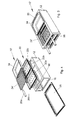
- the Fig. 1 and 2 show in a perspective view and in exploded view, a first embodiment of a cooking appliance according to the invention generally designated 10.
- the cooking utensil 10 includes a tool carrier 12 having an upper opening 14 dimensioned to allow a Gastronorm (GN) food container of GN size 1/1 to be hung therein.
- the device carrier 12 comprises a box-like housing 13, into which from an open front side 16 of a heating device in GN dimension in selectable height on support elements 18 can be inserted. If the housing 13 is made of stainless steel sheet, as in the embodiment shown here, the support members 18 are formed as support strips in the steel sheet, which are formed by beads.
- the device carrier 12 is closed at the open end 16 by a front flap, which is not shown, because it is not essential in the illustrated embodiment.
- the cooking appliance 10 shown and described here is, as already mentioned, a charcoal grill in GN format. Therefore, the electric heater commonly used in the prior art is replaced by a charcoal grate for receiving glowing charcoal (not shown) formed here by two GN containers 22a, 22b with a perforated bottom. Punched GN food containers are already known, but these have a variety of small holes that act as water outlet holes and / or steam passage holes.
- the bottomed bottom GN containers 22a, 22b each have three rows of four or five relatively large holes 22c acting as air circulation holes and ash exit holes.
- the GN containers 22a, 22b each have the GN size 1/2. They are going to the two in the Fig. 1 and 2 middle support elements 18 inserted as it Fig. 1 shows. Unlike conventional perforated GN food containers, the GN containers 22a, 22b are enamelled with perforated bottom.
- an assumed unit area of 10 cm ⁇ 10 cm has nine holes each having a diameter of 10 mm.
- a perforated GN food container used for the above purposes has approximately one hundred holes each about 4 mm in diameter on the same unit area.
- a GN grill grate 24 is inserted into the equipment rack 12 on the two top support elements 18, which is provided with two handles 26a, 26b.
- Fig. 1 shows the GN grill grate 24 inserted into the equipment rack 12.
- the GN grill grate 24 has the GN size 1/1.
- the ash collecting tray 28 has GN size 1/1 and is made of stainless steel sheet.
- the equipment carrier 12 is open or closed at the bottom and has supports for the ash collecting tray 28 at least on two sides of its bottom opening or bottom Fig. 1 the ash collecting tray 28 is shown inserted into the equipment carrier 12.
- the device carrier 12 has in its opposite to the end face 16 upper edge a plurality of openings 30 for air circulation.
- the 3 and 4 show a designated 10 'second embodiment of the cooking appliance according to the invention, in which a part of the GN grill grate 24 is replaced by a GN food container 34.
- the GN food container 34 is hung in the upper opening 14 of the device carrier 12, as in Fig. 3 is shown.
- the GN food container 34 has the GN size 1/2.
- the remaining smaller GN grill grate 24 ' which has the GN size 1/2, inserted into the equipment carrier 12, as in Fig. 3 is shown.
- the structure of the second embodiment of the cooking appliance 10 with the structure of the first embodiment according to the Fig. 1 and 2 therefore carries the same reference numerals and need not be further described to avoid repetition.
- GN containers 22a, 22b with perforated bottom instead of two such GN containers of size 1/2, a single punched GN container of size GN 1/1 could also be used
- glowing Charcoal filled which has been previously made in a special ignition cylinder, as it is commonly used in the known Weber ball grill, annealed.
- the GN grill grate 24 and the ash collecting tray 28 or the GN food container 34 and the GN grill grate 24 'and the ash collecting tray 28 are inserted into the equipment carrier 12.
- the grill grate 24 'could also by another GN food container such as GN food container 34 are replaced, so that the cooking appliance instead of the grill grate 24 or 24 'two side by side in the upper opening 14 of the device carrier 12 hinged flat GN food container 34 would have their floors each form a surface for grilling or frying.
- the or each GN food container 34 is made of a metallic multi-layer material and is usually a thermoplate container of the type mentioned. It has a particularly good thermal conductivity, so that such a container has virtually the same temperature at all points. This is very convenient for food preparation in such a container, because hot spots on which grill, cooking or baking could burn, are avoided.
- the or each food container 34 is also coated in particular with a glassy coating which is free of Teflon shares and is resistant to temperatures up to 400 ° C. The coating has a special surface hardness, so that it is not damaged by metal objects. For cleaning, therefore, conventional cleaning agents with cleaning sponges can be used.
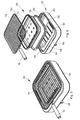
- FIGS. 5 and 6 show in perspective view or in exploded view of a generally designated 60 second embodiment of the cooking appliance according to the invention.
- a device carrier 62 of the cooking appliance 60 is a cuboid, only open at the top housing 63, in its upper opening 64 from above an ash collection tray 78, a GN container 72 with holes 72c existing in the ground coal meal and above a GN grill grate 74, having a handle 76, are used.
- a special feature is that the housing 63 forming the device carrier 62 has in plan view strongly rounded corners whose radius corresponds in each case to the rounding radius r according to EN 631-2.
- the housing 63 is adapted to the GN format in the most material-saving manner.
- the ash collecting tray 78 used in the cooking apparatus 60 is formed by a GN flat container as in the cooking apparatus 10.
- the side of the GN receptacle 78 forming GN container may be perforated as in the embodiments described below after the Fig. 7, 8 and 9a, 9b , The dimensioning of the holes 72c can be done this way as in the holes 22c described above.
- the housing 63 has a bottom wall 90 which is double-walled and has air slots 92 on its upper side adjacent to the upper opening 64 and on its side formed by the side wall. In Fig. 6 only the louvers 92 in the bottom wall 90 are visible.
- the GN grill grate 74 is inserted into the upper opening 64 as shown in FIG Fig. 5 can be seen.
- the housing 63 has a ledge 94, which projects radially inwardly in the upper opening 64, as a support element for the perforated GN container 72, which forms the coal meal.
- the ash catcher 78 when inserted into the housing 63, is spaced from the bottom wall 90 so as not to close the louvers 92, and a spacer (not shown) is interposed between the coalroot forming perforated GN container 72 and the ash catcher tray 78.
- the equipment carrier 62 has a support shoulder 96 for the GN grill grate 74.
- a side wall 63 of the housing extends axially downward.
- the side wall 63 merges into the bottom wall 90 closing the housing 63 below the ledge 94.
- the bottom wall 90 is associated with a slide 98 for selectively opening and closing at least a portion of the louvers 92. From the slider 98 is in Fig. 6 only the handle visible.
- the housing is manufactured as a deep-drawn part.
- the operation of the cooking appliance 60 is similar to that of the cooking appliance 10, with the difference that the first ash catch tray 78 and then the coal grate forming GN container 72 are used with perforated bottom in the equipment carrier 62, the GN container 72 with perforated bottom already may contain glowing coal or is then filled with red-hot coal, before finally the GN grill grate 74 is placed in the upper opening 64 on the support shoulder 96.
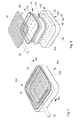
- FIGS. 7 and 8 show in perspective view or in exploded view a total designated 160 third embodiment of the cooking appliance according to the invention.
- a device support 162 of the cooking appliance 160 is a cuboid, open at the top and bottom housing 161 with a side wall 163, in the upper opening 164 from above an ash collecting tray 178, the GN 72 from a container 72 with perforated bottom with holes 72c existing Kohlerost 22 and above the GN grill grate 74, which has the handle 76, are used.
- the housing 161 forming the device carrier 162 has like the housing 63 in plan view strongly rounded corners whose radius corresponds to the rounding radius r according to EN 631-2.
- the housing 161 is also adapted to the GN format.
- the ash collecting pan 178 used in the cooking appliance 160 is formed by a flat GN container as in the cooking appliance 10 or the cooking appliance 60, but has a perforated side wall 180 in the cooking appliance 160 here.
- the housing 161 has a bottom wall 190 with a bottom opening 192 for receiving the ash collecting tray 178 formed by the GN container having the perforated side wall 180.
- an upper opening 164 of the housing 161 is according to Fig. 7 the GN grill grate 74 used.
- the housing 161 has a ledge 404 radially inwardly projecting in the upper opening 164 as a support member for the GN container 72 with perforated bottom forming the Kohlerost.
- the ash catch tray 178 When the ash catch tray 178 is inserted into the housing 161, it sits in the lower opening 192 of the housing and rests with its peripheral upper edge on the bottom wall 190. Below the bottom wall 190 is sufficient distance, so that the inserted ash collecting tray 178 od not with an under the cooking appliance 100 located table top. Like. Can come into contact.
- the holes formed in the side wall 165 are sized in number and in size so that when inserted ash collecting tray 178 is provided for a sufficient supply of air into the cooking appliance 100.
- FIGS. 7 and 8 Same parts as in the second embodiment of the FIGS. 5 and 6 are in the FIGS. 7 and 8 provided with the same reference numbers. The description of these parts with reference to the FIGS. 5 and 6 Thus, also applies as a description of these parts after the FIGS. 7 and 8 and therefore does not need to be repeated.
- a side wall 163 of the housing From the top of the housing 161 and thus also from the ledge 194, a side wall 163 of the housing extends axially downwardly. The side wall 163 merges into the bottom wall 190 bounding the housing 161 below the ledge 194, or carries the bottom wall 190 projecting inwardly therefrom.
- the bottom opening 192 of the housing 161 is formed to receive through the GN food container 72 formed with the perforated side wall 180 ash collecting tray 178th
- the operation of the cooking device 160 is similar to that of the cooking device 60, with the difference that first the ash catch tray 178 is inserted into the lower opening 192 of the bottom wall 190 and that then the coal frying GN container 72 is used with perforated bottom in the equipment rack 162 in that the GN container 72 with perforated bottom can already contain glowing coal or is subsequently filled with glowing coal, before finally the GN grill grate 74 is inserted into the upper opening 64 of the housing 161.
- the Fig. 9a and 9b show the cooking appliance 163 after Fig. 7 , in Fig. 9a in a side view in the direction of an arrow IXa in Fig. 7 and in Fig. 9b in section along the line IXb-IXb in Fig. 7 ,
- a further variant of the cooking appliance 163 namely the case in which the upper opening 164 of the housing 161 is dimensioned for receiving the coal frying GN container 72 with perforated bottom.
- the GN container 72 with perforated bottom sits in this case with the bottom of its upper edge on the top of the housing 161, as shown in the Fig. 9a and 9b can be seen.
- a grate 74 ' is sized so that it can be placed on the upper edge of the GN container 72 with perforated bottom to engage over it, as in the Fig. 9a and 9b can be seen.
- the holes in the perforated sidewall 180 are positioned so deeply that they are exposed below the bottom of the housing 161 with the ash catcher tray 178 inserted into the housing 161.
- Fig. 10a, 10b is shown in side view and in section a known cooking appliance, which is provided with an electric heater, which may be a ceran hob here.
- an electric heater which may be a ceran hob here.
- a comparison of Fig. 9a, 9b with the Fig. 10a, 10b can be easily seen that the cooking appliance 160 after the Fig. 9a, 9b a charcoal grill in GN format, in which the usual electric heater, the Fig. 10b can be seen, has been replaced by the two newly created GN containers 72 and 178 with perforated bottom or perforated side wall 180.
Landscapes
- Engineering & Computer Science (AREA)
- Food Science & Technology (AREA)
- Baking, Grill, Roasting (AREA)
Applications Claiming Priority (1)
| Application Number | Priority Date | Filing Date | Title |
|---|---|---|---|
| DE102009026111A DE102009026111A1 (de) | 2009-07-06 | 2009-07-06 | Kochgerät und insbesondere dafür vorgessehener gelochter GN-Behälter |
Publications (2)
| Publication Number | Publication Date |
|---|---|
| EP2327341A2 true EP2327341A2 (fr) | 2011-06-01 |
| EP2327341A3 EP2327341A3 (fr) | 2012-02-22 |
Family
ID=43307633
Family Applications (1)
| Application Number | Title | Priority Date | Filing Date |
|---|---|---|---|
| EP10168370A Withdrawn EP2327341A3 (fr) | 2009-07-06 | 2010-07-02 | Appareil de cuisson et notamment récipient gastronome perforé prévu à cet effet |
Country Status (2)
| Country | Link |
|---|---|
| EP (1) | EP2327341A3 (fr) |
| DE (1) | DE102009026111A1 (fr) |
Cited By (1)
| Publication number | Priority date | Publication date | Assignee | Title |
|---|---|---|---|---|
| CN109717726A (zh) * | 2019-01-31 | 2019-05-07 | 吉林省福泰厨具有限公司 | 一种便携式多功能炊具 |
Families Citing this family (3)
| Publication number | Priority date | Publication date | Assignee | Title |
|---|---|---|---|---|
| DE102016211043A1 (de) * | 2016-06-21 | 2017-12-21 | Lotusgrill Gmbh | Grill, Kocher und Holzkohlekammer für einen Grill, Kocher |
| CN106308563B (zh) * | 2016-11-28 | 2018-11-16 | 绍兴俪泰纺织科技有限公司 | 一种折叠式室外碳烤炉 |
| GB2559128A (en) * | 2017-01-25 | 2018-08-01 | Standard Brands Uk Ltd | Compact windproof solid fuel stove |
Citations (2)
| Publication number | Priority date | Publication date | Assignee | Title |
|---|---|---|---|---|
| EP0672520B1 (fr) | 1994-03-18 | 1999-03-03 | Clad Lizenz AG | Matériau composite métallique multicouche, déformable à froid et apte à l'emboutissage profond |
| DE19757004C2 (de) | 1997-12-20 | 2000-11-30 | Robert Detzer Gmbh & Co Kg | Kochzentrum mit Warm- und/oder Kaltausgabe |
Family Cites Families (7)
| Publication number | Priority date | Publication date | Assignee | Title |
|---|---|---|---|---|
| US2940381A (en) * | 1957-08-15 | 1960-06-14 | Cottongim | Barbecue stove |
| US4209006A (en) * | 1977-12-19 | 1980-06-24 | Marsalko Stephen C | Barbecue unit |
| DE20108432U1 (de) * | 2001-05-19 | 2001-09-20 | Weiß, Siegfried, 84556 Kastl | Glutbehälter für Kamingrill |
| DE20311800U1 (de) * | 2003-07-31 | 2003-09-25 | Busch, Dieter, 75172 Pforzheim | Transportabler Grill, Grillspieß und Grillset |
| US20070277800A1 (en) * | 2006-05-15 | 2007-12-06 | Chiang Chih-Ming | Barbecue |
| DE102008009248A1 (de) * | 2008-02-07 | 2009-01-22 | Rieber Gmbh & Co. Kg | Vorrichtung zum Zubereiten, Aufbewahren oder Ausgeben von Speisen |
| DE102009009842A1 (de) | 2009-02-20 | 2010-08-26 | Max Maier | Kochplatte, GN-Speisenbehälter, Kombination derselben und Verfahren zum Garen oder Fertiggaren von Speisen mit einer solchen Kombination |
-
2009
- 2009-07-06 DE DE102009026111A patent/DE102009026111A1/de not_active Withdrawn
-
2010
- 2010-07-02 EP EP10168370A patent/EP2327341A3/fr not_active Withdrawn
Patent Citations (2)
| Publication number | Priority date | Publication date | Assignee | Title |
|---|---|---|---|---|
| EP0672520B1 (fr) | 1994-03-18 | 1999-03-03 | Clad Lizenz AG | Matériau composite métallique multicouche, déformable à froid et apte à l'emboutissage profond |
| DE19757004C2 (de) | 1997-12-20 | 2000-11-30 | Robert Detzer Gmbh & Co Kg | Kochzentrum mit Warm- und/oder Kaltausgabe |
Cited By (2)
| Publication number | Priority date | Publication date | Assignee | Title |
|---|---|---|---|---|
| CN109717726A (zh) * | 2019-01-31 | 2019-05-07 | 吉林省福泰厨具有限公司 | 一种便携式多功能炊具 |
| CN109717726B (zh) * | 2019-01-31 | 2023-09-15 | 吉林省福泰厨具有限公司 | 一种便携式多功能炊具 |
Also Published As
| Publication number | Publication date |
|---|---|
| DE102009026111A1 (de) | 2011-01-13 |
| EP2327341A3 (fr) | 2012-02-22 |
Similar Documents
| Publication | Publication Date | Title |
|---|---|---|
| DE19757004C2 (de) | Kochzentrum mit Warm- und/oder Kaltausgabe | |
| EP2327341A2 (fr) | Appareil de cuisson et notamment récipient gastronome perforé prévu à cet effet | |
| DE60303647T2 (de) | Kochgerät | |
| EP0556698A2 (fr) | Support pour produits cuits ou grillés, en particulier pour volailles | |
| DE2623946C3 (de) | Umluft-Wärme-, -Back- und -Bratgerät | |
| DE102018125727A1 (de) | Gelenkmechanismus zum Zubereiten von Grillgerichten in einem Ofen | |
| DE102006011413A1 (de) | Gargerät | |
| DE69515451T2 (de) | Verbesserter Gaskocher | |
| EP3266280A1 (fr) | Appareil pour la préparation d'aliments | |
| DE2547704A1 (de) | Elektrischer rost, insbesondere fuer fleisch | |
| DE102015122742A1 (de) | Zusatzgrilleinheit | |
| DE29722573U1 (de) | Kochzentrum mit Warm- und/oder Kaltausgabe | |
| DE19505801C2 (de) | Herdmulde mit einem Kochfeld, dem ein Auflageelement zum Auflegen von Grill- oder Bratgut zugeordnet ist | |
| DE202005004888U1 (de) | Gargerät | |
| DE3928730A1 (de) | Grilleinrichtung | |
| DE29618202U1 (de) | Raclette-Tischkochgerät | |
| DE2411664C3 (de) | Heißluftgarungsgerät | |
| EP0697567B1 (fr) | Unités de cuisson combinées pour préparer des denrées chaudes | |
| DE19717316C2 (de) | Grillvorrichtung | |
| DE1930697A1 (de) | Koch- bzw. Grillherd | |
| DE516479C (de) | Elektrisch beheiztes Koch-, Brat- und Backgeraet in doppelwandiger Ausbildung mit konischem Luftzwischenraum zwischen inneren Topfwaenden und Aussenmantel | |
| DE2331270A1 (de) | Herd mit wahlweise austauschbaren kocheinheiten | |
| DE29910814U1 (de) | Küchenmodul | |
| DE19907073B4 (de) | Elektrogrill | |
| EP4193892A1 (fr) | Gril extérieur |
Legal Events
| Date | Code | Title | Description |
|---|---|---|---|
| PUAI | Public reference made under article 153(3) epc to a published international application that has entered the european phase |
Free format text: ORIGINAL CODE: 0009012 |
|
| AK | Designated contracting states |
Kind code of ref document: A2 Designated state(s): AL AT BE BG CH CY CZ DE DK EE ES FI FR GB GR HR HU IE IS IT LI LT LU LV MC MK MT NL NO PL PT RO SE SI SK SM TR |
|
| AX | Request for extension of the european patent |
Extension state: BA ME RS |
|
| RIC1 | Information provided on ipc code assigned before grant |
Ipc: A47J 37/07 20060101AFI20110920BHEP |
|
| PUAL | Search report despatched |
Free format text: ORIGINAL CODE: 0009013 |
|
| AK | Designated contracting states |
Kind code of ref document: A3 Designated state(s): AL AT BE BG CH CY CZ DE DK EE ES FI FR GB GR HR HU IE IS IT LI LT LU LV MC MK MT NL NO PL PT RO SE SI SK SM TR |
|
| AX | Request for extension of the european patent |
Extension state: BA ME RS |
|
| RIC1 | Information provided on ipc code assigned before grant |
Ipc: A47J 37/07 20060101AFI20120113BHEP |
|
| STAA | Information on the status of an ep patent application or granted ep patent |
Free format text: STATUS: THE APPLICATION IS DEEMED TO BE WITHDRAWN |
|
| 18D | Application deemed to be withdrawn |
Effective date: 20120823 |