EP2326437B1 - Verfahren und vorrichtung zur kühlung und trocknung eines warmbandes oder eines blechs in einem walzwerk - Google Patents
Verfahren und vorrichtung zur kühlung und trocknung eines warmbandes oder eines blechs in einem walzwerk Download PDFInfo
- Publication number
- EP2326437B1 EP2326437B1 EP09777663.7A EP09777663A EP2326437B1 EP 2326437 B1 EP2326437 B1 EP 2326437B1 EP 09777663 A EP09777663 A EP 09777663A EP 2326437 B1 EP2326437 B1 EP 2326437B1
- Authority
- EP
- European Patent Office
- Prior art keywords
- strip
- sheet
- rolling mill
- mill according
- drying
- Prior art date
- Legal status (The legal status is an assumption and is not a legal conclusion. Google has not performed a legal analysis and makes no representation as to the accuracy of the status listed.)
- Not-in-force
Links
- 238000001035 drying Methods 0.000 title claims description 59
- 238000005096 rolling process Methods 0.000 title claims description 49
- 238000001816 cooling Methods 0.000 title claims description 48
- 238000000034 method Methods 0.000 title claims description 27
- 239000002184 metal Substances 0.000 title claims description 5
- XLYOFNOQVPJJNP-UHFFFAOYSA-N water Substances O XLYOFNOQVPJJNP-UHFFFAOYSA-N 0.000 claims description 52
- 239000007921 spray Substances 0.000 claims description 30
- 239000007788 liquid Substances 0.000 claims description 26
- IJGRMHOSHXDMSA-UHFFFAOYSA-N Atomic nitrogen Chemical compound N#N IJGRMHOSHXDMSA-UHFFFAOYSA-N 0.000 claims description 24
- 239000000110 cooling liquid Substances 0.000 claims description 22
- 239000007789 gas Substances 0.000 claims description 22
- 238000009826 distribution Methods 0.000 claims description 14
- 229910052757 nitrogen Inorganic materials 0.000 claims description 12
- 230000005855 radiation Effects 0.000 claims description 11
- 239000002826 coolant Substances 0.000 claims description 9
- 238000010438 heat treatment Methods 0.000 claims description 5
- 238000011144 upstream manufacturing Methods 0.000 claims description 5
- 230000008569 process Effects 0.000 claims description 4
- 230000009471 action Effects 0.000 claims description 3
- 239000012530 fluid Substances 0.000 claims description 3
- 239000000463 material Substances 0.000 claims description 2
- 239000004033 plastic Substances 0.000 claims description 2
- 229920003023 plastic Polymers 0.000 claims description 2
- 230000001105 regulatory effect Effects 0.000 claims 2
- 238000012216 screening Methods 0.000 claims 2
- 238000001514 detection method Methods 0.000 claims 1
- 238000005098 hot rolling Methods 0.000 claims 1
- 238000003801 milling Methods 0.000 claims 1
- 238000012544 monitoring process Methods 0.000 claims 1
- 230000010355 oscillation Effects 0.000 claims 1
- 239000012858 resilient material Substances 0.000 claims 1
- 229910000831 Steel Inorganic materials 0.000 description 7
- 239000010959 steel Substances 0.000 description 7
- 239000000498 cooling water Substances 0.000 description 5
- 238000001704 evaporation Methods 0.000 description 5
- 238000005507 spraying Methods 0.000 description 5
- 238000007605 air drying Methods 0.000 description 4
- 206010013786 Dry skin Diseases 0.000 description 3
- 238000007664 blowing Methods 0.000 description 3
- 230000008020 evaporation Effects 0.000 description 3
- 230000001419 dependent effect Effects 0.000 description 2
- 230000000694 effects Effects 0.000 description 2
- 230000003647 oxidation Effects 0.000 description 2
- 238000007254 oxidation reaction Methods 0.000 description 2
- 239000002245 particle Substances 0.000 description 2
- 238000003860 storage Methods 0.000 description 2
- 238000004804 winding Methods 0.000 description 2
- OKTJSMMVPCPJKN-UHFFFAOYSA-N Carbon Chemical compound [C] OKTJSMMVPCPJKN-UHFFFAOYSA-N 0.000 description 1
- 229910000885 Dual-phase steel Inorganic materials 0.000 description 1
- 241000475481 Nebula Species 0.000 description 1
- 230000004913 activation Effects 0.000 description 1
- 230000002411 adverse Effects 0.000 description 1
- 238000013459 approach Methods 0.000 description 1
- 229910001566 austenite Inorganic materials 0.000 description 1
- 230000008901 benefit Effects 0.000 description 1
- 238000006243 chemical reaction Methods 0.000 description 1
- 238000004140 cleaning Methods 0.000 description 1
- 239000000567 combustion gas Substances 0.000 description 1
- 239000012809 cooling fluid Substances 0.000 description 1
- 238000007599 discharging Methods 0.000 description 1
- 239000013013 elastic material Substances 0.000 description 1
- 238000011156 evaluation Methods 0.000 description 1
- 238000007667 floating Methods 0.000 description 1
- 230000006698 induction Effects 0.000 description 1
- 238000002347 injection Methods 0.000 description 1
- 239000007924 injection Substances 0.000 description 1
- 238000007689 inspection Methods 0.000 description 1
- 230000002452 interceptive effect Effects 0.000 description 1
- JEIPFZHSYJVQDO-UHFFFAOYSA-N iron(III) oxide Inorganic materials O=[Fe]O[Fe]=O JEIPFZHSYJVQDO-UHFFFAOYSA-N 0.000 description 1
- 229910000734 martensite Inorganic materials 0.000 description 1
- 230000002829 reductive effect Effects 0.000 description 1
- 230000000284 resting effect Effects 0.000 description 1
- 230000000717 retained effect Effects 0.000 description 1
- 238000000638 solvent extraction Methods 0.000 description 1
- 238000001228 spectrum Methods 0.000 description 1
- 230000006641 stabilisation Effects 0.000 description 1
- 238000011105 stabilization Methods 0.000 description 1
- 230000008016 vaporization Effects 0.000 description 1
- 239000002699 waste material Substances 0.000 description 1
Images


Classifications
-
- B—PERFORMING OPERATIONS; TRANSPORTING
- B08—CLEANING
- B08B—CLEANING IN GENERAL; PREVENTION OF FOULING IN GENERAL
- B08B5/00—Cleaning by methods involving the use of air flow or gas flow
-
- B—PERFORMING OPERATIONS; TRANSPORTING
- B21—MECHANICAL METAL-WORKING WITHOUT ESSENTIALLY REMOVING MATERIAL; PUNCHING METAL
- B21B—ROLLING OF METAL
- B21B45/00—Devices for surface or other treatment of work, specially combined with or arranged in, or specially adapted for use in connection with, metal-rolling mills
- B21B45/02—Devices for surface or other treatment of work, specially combined with or arranged in, or specially adapted for use in connection with, metal-rolling mills for lubricating, cooling, or cleaning
- B21B45/0269—Cleaning
- B21B45/0275—Cleaning devices
- B21B45/0278—Cleaning devices removing liquids
- B21B45/0281—Cleaning devices removing liquids removing coolants
-
- B—PERFORMING OPERATIONS; TRANSPORTING
- B21—MECHANICAL METAL-WORKING WITHOUT ESSENTIALLY REMOVING MATERIAL; PUNCHING METAL
- B21B—ROLLING OF METAL
- B21B45/00—Devices for surface or other treatment of work, specially combined with or arranged in, or specially adapted for use in connection with, metal-rolling mills
- B21B45/02—Devices for surface or other treatment of work, specially combined with or arranged in, or specially adapted for use in connection with, metal-rolling mills for lubricating, cooling, or cleaning
-
- B—PERFORMING OPERATIONS; TRANSPORTING
- B26—HAND CUTTING TOOLS; CUTTING; SEVERING
- B26B—HAND-HELD CUTTING TOOLS NOT OTHERWISE PROVIDED FOR
- B26B13/00—Hand shears; Scissors
- B26B13/28—Joints
-
- B—PERFORMING OPERATIONS; TRANSPORTING
- B26—HAND CUTTING TOOLS; CUTTING; SEVERING
- B26B—HAND-HELD CUTTING TOOLS NOT OTHERWISE PROVIDED FOR
- B26B21/00—Razors of the open or knife type; Safety razors or other shaving implements of the planing type; Hair-trimming devices involving a razor-blade; Equipment therefor
- B26B21/08—Razors of the open or knife type; Safety razors or other shaving implements of the planing type; Hair-trimming devices involving a razor-blade; Equipment therefor involving changeable blades
- B26B21/14—Safety razors with one or more blades arranged transversely to the handle
-
- F—MECHANICAL ENGINEERING; LIGHTING; HEATING; WEAPONS; BLASTING
- F26—DRYING
- F26B—DRYING SOLID MATERIALS OR OBJECTS BY REMOVING LIQUID THEREFROM
- F26B13/00—Machines and apparatus for drying fabrics, fibres, yarns, or other materials in long lengths, with progressive movement
- F26B13/10—Arrangements for feeding, heating or supporting materials; Controlling movement, tension or position of materials
-
- F—MECHANICAL ENGINEERING; LIGHTING; HEATING; WEAPONS; BLASTING
- F26—DRYING
- F26B—DRYING SOLID MATERIALS OR OBJECTS BY REMOVING LIQUID THEREFROM
- F26B13/00—Machines and apparatus for drying fabrics, fibres, yarns, or other materials in long lengths, with progressive movement
- F26B13/24—Arrangements of devices using drying processes not involving heating
- F26B13/28—Arrangements of devices using drying processes not involving heating for applying pressure; for brushing; for wiping
-
- F—MECHANICAL ENGINEERING; LIGHTING; HEATING; WEAPONS; BLASTING
- F26—DRYING
- F26B—DRYING SOLID MATERIALS OR OBJECTS BY REMOVING LIQUID THEREFROM
- F26B21/00—Arrangements or duct systems, e.g. in combination with pallet boxes, for supplying and controlling air or gases for drying solid materials or objects
- F26B21/14—Arrangements or duct systems, e.g. in combination with pallet boxes, for supplying and controlling air or gases for drying solid materials or objects using gases or vapours other than air or steam, e.g. inert gases
-
- B—PERFORMING OPERATIONS; TRANSPORTING
- B21—MECHANICAL METAL-WORKING WITHOUT ESSENTIALLY REMOVING MATERIAL; PUNCHING METAL
- B21B—ROLLING OF METAL
- B21B45/00—Devices for surface or other treatment of work, specially combined with or arranged in, or specially adapted for use in connection with, metal-rolling mills
- B21B45/02—Devices for surface or other treatment of work, specially combined with or arranged in, or specially adapted for use in connection with, metal-rolling mills for lubricating, cooling, or cleaning
- B21B45/0203—Cooling
- B21B45/0209—Cooling devices, e.g. using gaseous coolants
- B21B45/0215—Cooling devices, e.g. using gaseous coolants using liquid coolants, e.g. for sections, for tubes
- B21B45/0218—Cooling devices, e.g. using gaseous coolants using liquid coolants, e.g. for sections, for tubes for strips, sheets, or plates
Definitions
- the invention relates to a method and an apparatus for drying a continuous belt or sheet in a rolling mill, see for example WO-A 2006/109380 ,
- From the DE 28 44 434 A1 is a method for the suction of liquid residues of continuous sheets and strips, especially in rolling mills and strip processing, out, in which in a defined area across the top and bottom of the sheet metal by a negative pressure of at least 0.4 bar generated Saugluftströme be performed and the recorded Liquid is separated from the suction air.
- relatively low temperatures for example in the Range between 25 ° and 400 ° C
- At least one belt drying device is provided behind the cooling device. In the case of a steel strip, this ensures that the residual moisture is removed from the strip surface before being wound on the reel or stacking the metal sheets.
- the moisture sensors control or regulate actuators of the drying device, in particular for adjusting the amount of drying medium or the pressure of the drying medium.
- these measured values can be reliably detected.
- the actuators of the cooling section such as spray nozzles or valves for adjusting the amount of water or water distribution, set reliably and thus can be used for temperature control.
- the temperatures or the temperature distribution on the surface of the strip or the sheet are detected.
- the temperature signals or the measured temperature distributions allow conclusions about the moisture state of the strip surface and can be used as an indicator for this purpose.
- a humidity sensor can therefore also serve a temperature scanner.
- the detected moisture condition is stored in a process model.
- the further processing of the coil can be derived (wrapping, direct processing, storage, etc.).
- the actuators of the cooling section in particular spray nozzles or valves for adjusting the amount of water, the ratio of the top supplied water to the amount of water supplied from below and the water distribution over the width of the band or the sheet set.
- Rollers or rollers are advantageously used in the area of the drying device, which squeeze the cooling liquid from the upper side of the strip or sheet.
- a fluid, in particular further cooling liquid, for removing the adhering to the sheet or the hot strip cooling liquid layer is applied against the direction of the belt or the sheet.
- the band or the sheet is dried by means of a pressurized gas, in particular by means of compressed air.
- a pressurized gas in particular by means of compressed air.
- the gas can only be inflated to the top or both sides of the belt or sheet.
- the compressed air is generated by means of a fan, compressed air nozzles or a compressed air station or air quantity amplifier and in a suitable direction, for example against and across the tape, on the tape or sheet or in one of a roll with the tape or ., the gap formed or the corner is blown.
- the drying effect can additionally by suitably positioned vacuum zones, eg. As suction, supplemented and improved.
- the role can, for example, a Be a driver role. In a gap formed by a roll and the band hot or cold air can be introduced, which is deflected there automatically deflected to the sides of the belt or the sheet and entrains water droplets.
- Another advantage is a method in which the moisture remaining on the belt or the sheet is removed by means of flames and gases generated by Schubrennem.
- liquid gas in particular by liquid nitrogen, can be removed on the belt or the sheet remaining moisture.
- the amount of the liquid gas is such that the strip or the sheet is additionally cooled.
- the object of the invention is also achieved by a rolling mill equipped with a cooling section for rolling a strip or sheet with the features of claim 17.
- sensors for reliably measuring the temperature are provided in or behind the drying device. Due to the measured temperature distribution actuators are in an upstream of the drying device cooling section, in particular spray nozzles or valves for adjusting the amount of the cooling liquid, for adjusting the coolant supply from above or from below and over the width of the belt or the sheet set, the Actuators are in particular parts of a control device or a plurality of control devices.
- the drying device In order to remove a large part of the resting on the tape cooling water, the drying device on rollers or rollers on which the band or the sheet is passed and which squeeze the cooling liquid from the belt or sheet.
- these rollers additionally have a further function, for example as deflection, straightening rollers or driver rollers.
- the rollers have a metal or plastic surface or other elastic material on the surface or in the form of a roller brush. Either only one pair of rollers or a plurality of pairs of rollers or individual rollers are provided for this task.
- the process of squeezing out the excess water is preferably carried out by the additional use of the rollers or rollers in the direction of the belt or sheet upstream water spray, from which water is sprayed against the direction of the tape or the sheet.
- devices can be arranged, which spray the water transversely to the direction of the tape or the sheet.
- several successively mounted spray bars may be arranged upstream of a role.
- the drying device comprises a compressed air dryer.
- compressed air drying can also be used without the presence of a squeeze roller.
- a high-pressure L jossabspritzung pushes back the existing water on the sheet or tape.
- the compressed air dryer is equipped with a blower.
- This preferably has one or more fans.
- the fan sucks in air, which is blown against baffles and one or more, in particular rectangular, air nozzles against and across the direction of the tape or the sheet.
- the outlet width of the air nozzles can be adjusted by adjustable side plates to the width of the band or the sheet.
- nozzle arrangement and a suitably selected nozzle size By appropriate nozzle arrangement and a suitably selected nozzle size, a different effect over the width of the belt can be generated.
- a targeted arrangement of the nozzles or the slots for example only at the band edge or only in the central region of the band, is possible.
- the compressed air drying can be used either only on the top of the tape or on both sides of the tape. Again, the air flow is directed either as such against the belt or preferably also, in particular outlet side, in the gap or corner of a role, such as a driver roller, steered.
- movable floating nozzles in the form of an air cushion device are provided, which are used as additional means for removing residual moisture from the belt.
- the air pressure can also be generated next to the belt or in an external compressed air station.
- hot air in particular in combination with hot gas, can be generated, for example as a waste product from another device of the plant.
- the drying device comprises sensors for measuring the flatness of the strip or the sheet, which is arranged in particular in the running direction behind the belt drying.
- the rolling mill may also include a heating burner.
- a heating burner a plurality of burners arranged over the width of the strip, in particular DFI (direct flame impingement) burners directed against the band.
- DFI direct flame impingement
- the use of only a single burner is sufficient. Due to the high flame temperature, the residual water evaporates on the strip surface. The flame settings are so dimensioned that during the drying process only a slight increase in strip temperature occurs and in this way the strip properties are not adversely affected.
- the exhaust gases of the burner are removed by a suction device.
- the roller table rollers are heat resistant in the burner area.
- the drying device comprises an arrangement, in particular a spray nozzle bar, for acting on the surface of the strip or the sheet with a liquid gas, in particular with liquid nitrogen.
- a liquid gas in particular with liquid nitrogen.
- liquid nitrogen is sprayed or sprayed from arranged on one or more manifolds nozzles against the tape. The nitrogen cools the moisture still on the belt to small ice particles, then the ice sublimates and escapes from the belt surface together with the evaporating nitrogen. In this way, the tape is dried. The water vapor or the water gas and the gaseous nitrogen are sucked off or blown off again above or behind the spray device.
- liquid nitrogen is also used, depending on the type of steel, to simultaneously achieve additional cooling of the strip to lower temperatures and a positive influence on the mechanical properties by stabilization or conversion of the still unconverted retained austenite.
- the drying device comprises an induction heater, or a radiation dryer, in particular an infrared or a microwave radiation dryer.
- the drying device advantageously comprises a device for extracting moisture from the surface of the strip or the sheet.
- additional radiation dryers and / or devices for extracting moisture and / or spray jet bars for applying a liquid gas to the surface of the belt may also advantageously be arranged in the region of a reel driver or reel downstream of the drying device.
- a device which causes the strip or the sheet to oscillate, in particular by means of a pulsating air flow or pulsating magnetic fields, by roller conveyor rolls offset in the longitudinal direction.
- the pulsating air flow can be generated, for example, with a rotating air damper.
- the coils consisting of the wound strip can also be dried, in particular by blowing. Preferably, they are stored before storage in a dry air, hot air or hot gas space.
- the devices used in the drying of the strip can be used at least partially also in the area of the reel on which the coils are wound up.
- All means for removing the cooling water and / or moisture from the belt or sheet can either be installed stationary or they can be swiveled into the transport line of the belt as needed, driven into it or lowered or moved in the direction of the running plane of the belt.
- the use of the device is dependent on the reel temperature, for example, for tapes with a temperature of less than 400 ° C, and depending on the thickness of the tape.
- the activation of the individual units for removing the cooling water and the drying and dehumidifying devices is preferably carried out by a central computing and control device, in particular by a process computer.
- the various facilities for drying and dehumidifying the tape can be used individually or in any combination with each other.
- the various devices for drying and dehumidifying the tape or coils can be used in a separate tape rewinding system and possibly combined with other process steps.
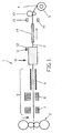
- a hot strip mill 1 ( Fig. 1 ) includes a plurality of rolling stands, of which the last rolling stand 2 is shown to roll a hot strip 3 and feed a reel 4, where it is wound into a coil 5.
- a cooling device 6 which includes various cooling units, for example, a plurality of devices 7, 8 for laminar belt cooling by means of a coolant, for example, laminar flowing jets of coolant, in particular with cooling water. Furthermore, cooling water is sprayed onto the belt 3, for example with a device 9 for intensive cooling or spray cooling.
- the devices 7 to 9 are mounted on the bottom and the top of the belt 3, so that it still has a temperature after passing through the cooling device 6, which is for example below 400 ° C. Then, the tape 3 is continued in a belt dryer 10 black box, which removes the tape 3 moisture on the surface.
- the band 3 is dried, for example, with a water longitudinal spray combined with a compressed air device.
- the belt dryer 10 preferably also includes a temperature scanner or a temperature sensor 11 and a flatness measuring device 12.
- the temperature sensor 11 measures the temperature of the belt 3 preferably bolometrically, ie by measuring the radiated from the band 3 radiation spectrum. Therefore, it is necessary to shield the temperature sensor 11 from other sources of radiation, for example, lamps, outside light, etc., which are located in the measuring range or are collected there. For this purpose, for example, a radiation-transparent cover above or possibly next to the measuring range is suitable.
- Safe and accurate strip temperature sensing improves temperature control and can be used selectively to achieve e.g. set a coil winding temperature of 200 ° C, at which the evaporation of the water is just happening.
- the flatness meter 12 determines the flatness of the belt 3 so as to be able to adjust actuators for controlling the flatness if necessary.
- the hot strip flatness behind the rolling train 2 and the belt temperature distribution over the bandwidth can be selectively influenced.
- Moisture sensors 15, 16 in the outlet region of the hot strip mill 1 register any residual moisture that may still be present in order to supply corresponding signal quantities to a regulator for controlling the feeding of a drying medium in the belt dryer 10.
- a humidity sensor can also serve temperature scanner with appropriate temperature evaluation.
- rollers 18 are suitable, which form a pair of rollers with a mounted on the bottom roller 19.
- the pair of rollers 18, 19 has either only the task of removing the liquid, but it can also fulfill additional functions by serving to drive the belt 3, or by the two rollers 18, 19 are used to straighten the belt 3, wherein at least one of the two rollers 18, 19 is height adjustable or can be adjusted in the direction of tape travel.
- the squeezing action of the rollers 18, 19 for the removal of the liquid film on the belt 3 is further supported by a water spray bar 20 or a blowing device for blowing compressed air, in particular against the direction of the belt 3, by sprayed water or the inflated compressed air a considerable Proportion of the cooling liquid removed before it gets into the gap between the roller 18 and the belt 3.
- a water spray bar 20 or a blowing device for blowing compressed air, in particular against the direction of the belt 3, by sprayed water or the inflated compressed air a considerable Proportion of the cooling liquid removed before it gets into the gap between the roller 18 and the belt 3.
- another water spray bar 21 or compressed air beam for introducing compressed air transversely to the running direction of the belt 3 can remove the water layer from the belt 3.
- rollers 18, 19, 22, 23, 24 can be arranged one behind the other offset from the belt 3 to squeeze the liquid layer 17, wherein a plurality of these rollers 18, 19, 22, 23, 24 have different functions, for example, additionally as driver or straightening rollers.
- a device 25 for compressed air drying is the device for removing the cooling liquid layer 17 serving arrangement of the rollers 18, 19, a device 25 for compressed air drying provided, which can be used without the squeezing rollers 18, 19 depending on the application.
- a high-pressure Llindsabspritzung urges the cooling liquid from the belt 3.
- the device 25 comprises above and preferably also below the belt 3, a fan 26, each with a plurality of juxtaposed fans for the intake of air.
- baffles 27 and one or more air nozzles 28, 29, 30, the compressed air is blown against the belt surface, preferably against the Tape direction.
- a temperature sensor 11 and a flatness measuring device 12 are provided to determine the properties of the strip 3, so that even though the blowers 26 are integrated into a control loop, make appropriate adjustments to the temperature and / or intensity of the compressed air inflation on the belt 3 and use means to improve the flatness of the belt 3.
- a plurality of heating torches 32 to 35 preferably directed from both the top and from the bottom against the belt 3 to dry it. Due to the high flame temperature, the remaining water still evaporates on the belt 3.
- the flame settings are dimensioned so that the band properties do not worsen, in particular even taking into account the heat of evaporation required by the water.
- the exhaust gases of the burners 32 to 35 are sucked off by a suction device 36.
- Roller table rollers 37 on the underside of the band 3 are made heat-resistant in the region of the burners 34, 35.
- the moisture is removed using sprayers 38-40, which apply a liquid gas, especially liquid nitrogen, to the belt 3, which cools the water to ice.
- a liquid gas especially liquid nitrogen
- the vaporizing nitrogen then tears the water with it, which also evaporates.
- the suction device 36 sucks both the nitrogen and the water.
- an air blow is provided behind this spraying device.
- the spraying device 38-40 can be arranged in the region of the roller table rollers, as in FIG. 5 shown. An arrangement of the spray device is also provided directly behind the reel drive rollers 13.
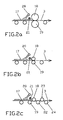
- Fig. 6 are the in Fig. 3 to 5 illustrated measures for drying the tape combined.
- pinch rollers 18, 19 in the direction of a double arrow A raisable and lowerable blower 26 with an air nozzle 28 on the top of the belt 3
- raised and lowered spray device 38 and a in Direction of a double arrow C can be raised and lowered burner 32 provided in succession.
- the spray device 38 applies either liquid gas or warm air to the belt 3. Evaporating gases and combustion gases are sucked through the suction device 36. Under the cover 31, the temperature sensor 11 and the flatness meter 12 are mounted.
- a water spray bar 20 ensures efficient and powerful longitudinal water spraying.
- an optional fan 26 the spray device 40 and the burner 34 are preferably arranged.
- the cooling of the roller table rollers 37 behind the cooling section or the drying device, the drive rollers 18, 19, etc. can be deactivated.
- Spraying devices and burners can optionally be used alternatively. Conventional fans keep the environment of sensors and gauges 11 free of any nuisance nebulas.
- a graph 41 shows how the water layer 17 on the belt 3 is gradually degraded over the course of the belt 3 by the various successive measures. The various aggregates gradually remove the water from the belt 3.
- a plurality of drying and cooling devices are arranged after the last rolling stands 2 in a row, wherein the band 3 at different locations between the stands 2 and the reel drivers 13 by side guides 14 is performed.
- the belt 3 first passes through a first device 42 for intensive belt cooling and then a spray 43 for pushing back the cooling liquid, from the belt 3.
- the belt 3 is dried under a blower 44 for applying air to the belt third carried out.
- a device 45 for laminar belt cooling which is followed by a further device 46 for intensive belt cooling.
- a temperature scanner 47 and a flatness measuring device 48 may be arranged, which is indicated here only by two arrows.
- a water spray bar 49 is arranged downstream for the removal of coolant present on the belt 3.
- another drying device may be provided instead of the blower 50.
- the strip 3 then passes through at least one spray device 51, which applies a liquid gas in spray form for cooling and entrainment of moisture particles, in particular drops of water, onto the strip 3.
- the tape 3 is passed again between reel pairs of reel rollers 13 before it reaches one of two reels 52, 53, where it is wound into a coil.
- a strip tension is built up in an advantageous manner at an early stage up to the last active rolling stand 2. This improves the uniformity of the belt cooling and reduces belt waviness, which positively influences the drying process. With an almost dry surface, the flatness and the temperature distribution at the beginning of the cooling section can also be detected at an early stage. Both values are then available for control purposes.
- sequence of cooling and drying devices for applying and removing fluids applied for cooling can be realized according to this invention.
- the sequence of the devices can be adjusted so that the desired crystalline microstructures and microstructure within the strip 3 and thus the desired material properties are achieved.
- Arrangements for Wasserl Kunststoffsabspritzung and lateral air blower, which are preferably directed against the direction or across the belt 3, can be provided here.
- the facilities for Abschotten the water, for belt drying, for building a tape tension, etc. also forward and / or perform in the back of the cooling section.
Landscapes
- Engineering & Computer Science (AREA)
- Mechanical Engineering (AREA)
- General Engineering & Computer Science (AREA)
- Textile Engineering (AREA)
- Life Sciences & Earth Sciences (AREA)
- Forests & Forestry (AREA)
- Drying Of Solid Materials (AREA)
- Metal Rolling (AREA)
Applications Claiming Priority (3)
| Application Number | Priority Date | Filing Date | Title |
|---|---|---|---|
| DE102008038277 | 2008-08-18 | ||
| DE102009023359A DE102009023359A1 (de) | 2008-08-18 | 2009-05-29 | Verfahren und Vorrichtung zur Kühlung und Trocknung eines Warmbandes oder eines Bleches in einem Walzwerk |
| PCT/EP2009/005660 WO2010020343A1 (de) | 2008-08-18 | 2009-08-05 | Verfahren und vorrichtung zur kühlung und trocknung eines warmbandes oder eines blechs in einem walzwerk |
Publications (2)
| Publication Number | Publication Date |
|---|---|
| EP2326437A1 EP2326437A1 (de) | 2011-06-01 |
| EP2326437B1 true EP2326437B1 (de) | 2013-10-02 |
Family
ID=41566930
Family Applications (1)
| Application Number | Title | Priority Date | Filing Date |
|---|---|---|---|
| EP09777663.7A Not-in-force EP2326437B1 (de) | 2008-08-18 | 2009-08-05 | Verfahren und vorrichtung zur kühlung und trocknung eines warmbandes oder eines blechs in einem walzwerk |
Country Status (9)
| Country | Link |
|---|---|
| US (1) | US9358598B2 (enExample) |
| EP (1) | EP2326437B1 (enExample) |
| JP (1) | JP5490799B2 (enExample) |
| KR (1) | KR101335441B1 (enExample) |
| CN (1) | CN102123801A (enExample) |
| BR (1) | BRPI0917303A2 (enExample) |
| DE (1) | DE102009023359A1 (enExample) |
| RU (1) | RU2011110263A (enExample) |
| WO (1) | WO2010020343A1 (enExample) |
Families Citing this family (33)
| Publication number | Priority date | Publication date | Assignee | Title |
|---|---|---|---|---|
| KR101525721B1 (ko) * | 2011-05-23 | 2015-06-03 | 신닛테츠스미킨 카부시키카이샤 | 열간 프레스 성형 방법 및 열간 프레스 성형 금형 |
| CN102615103A (zh) * | 2012-04-19 | 2012-08-01 | 重庆大学 | 具有抛光功能的镁合金板材轧制装置 |
| JP6023563B2 (ja) * | 2012-11-19 | 2016-11-09 | アイシン精機株式会社 | ロール成形方法およびロール成形装置 |
| DE102013221710A1 (de) | 2013-10-25 | 2015-04-30 | Sms Siemag Aktiengesellschaft | Aluminium-Warmbandwalzstraße und Verfahren zum Warmwalzen eines Aluminium-Warmbandes |
| CN106076951A (zh) * | 2016-08-16 | 2016-11-09 | 无锡尊宝电动车有限公司 | 一种能对金属表面进行冲洗去锈斑的清洗箱 |
| RU2748536C2 (ru) * | 2017-01-24 | 2021-05-26 | Прайметалз Текнолоджиз Аустриа ГмбХ | Литейно-прокатная установка и способ обработки заготовки посредством такой установки |
| KR101984372B1 (ko) * | 2017-02-01 | 2019-09-03 | 대한철강주식회사 | 평탄화가 가능한 리코일러 장치 |
| CN107511357A (zh) * | 2017-10-21 | 2017-12-26 | 南京同旺铝业有限公司 | 一种铝板的在线清洗装置 |
| CN107597643A (zh) * | 2017-10-21 | 2018-01-19 | 南京同旺铝业有限公司 | 一种铝板清洗装置 |
| CN107887578A (zh) * | 2017-12-25 | 2018-04-06 | 天能电池(芜湖)有限公司 | 蓄电池铅带压轧处理装置 |
| CN109028868A (zh) * | 2018-06-28 | 2018-12-18 | 嘉兴市集珵机械有限公司 | 具备检查截面尺寸功能的双重干燥导轮架 |
| CN109332428A (zh) * | 2018-08-15 | 2019-02-15 | 嘉兴塘东汽车配件有限公司 | 一种方便调节的钢材压延装置 |
| CN109226380A (zh) * | 2018-08-24 | 2019-01-18 | 芜湖鸣人热能设备有限公司 | 一种钢条压弯冷却设备 |
| CN109501181A (zh) * | 2018-12-31 | 2019-03-22 | 台州市春丰机械有限公司 | 一种滴灌带的排水装置 |
| EP3799945B1 (en) * | 2019-08-21 | 2024-07-17 | Jingjin Equipment Inc. | Blowback blockage removing apparatus for drying machine dust screen, dust-proof device, and drying machine |
| US20220349038A1 (en) * | 2019-10-16 | 2022-11-03 | Novelis Inc. | Rapid quench line |
| CN110935736A (zh) * | 2019-11-25 | 2020-03-31 | 山东宏旺实业有限公司 | 一种冷轧带钢余热回收利用装置及其使用方法 |
| FR3104178B1 (fr) * | 2019-12-09 | 2022-12-02 | Fives Stein | Dispositif et procede de traitement thermique des aciers comprenant un refroidissement humide |
| JP6955544B2 (ja) * | 2019-12-27 | 2021-10-27 | 中外炉工業株式会社 | 金属ストリップの冷却装置 |
| CN111515259B (zh) * | 2020-04-28 | 2021-11-23 | 重庆钢铁股份有限公司 | 防干扰冷却系统及防干扰冷却控制方法 |
| TWM599894U (zh) * | 2020-05-14 | 2020-08-11 | 佳格食品股份有限公司 | 噴料滾筒系統 |
| CN112284113A (zh) * | 2020-11-27 | 2021-01-29 | 南京亚鼎光学有限公司 | 一种pvb胶片含水率调整的装置 |
| CN112414152A (zh) * | 2020-12-01 | 2021-02-26 | 菏泽双龙冶金机械有限公司 | 一种冶金冷却机构 |
| CN112404149B (zh) * | 2020-12-30 | 2022-07-05 | 浙江传播者金属装饰材料有限公司 | 一种防止异物压入的轧机装置 |
| CN112985023B (zh) * | 2021-01-30 | 2022-05-06 | 苏州和记纺织科技有限公司 | 一种适用于纺织布的快速干燥设备 |
| CN113619081B (zh) * | 2021-08-02 | 2023-02-03 | 深圳市富发世纪科技有限公司 | 一种自动清理冷却式塑料制品成型机 |
| CN114378991B (zh) * | 2021-12-15 | 2025-01-24 | 广东华凤环保科技有限公司 | 一种应用于农业薄膜制造的薄膜冷却定型工艺 |
| KR102420612B1 (ko) * | 2022-01-06 | 2022-07-13 | 조출규 | 에어건조장치의 스트립 공급에 따른 온도 제어시스템 |
| KR102741161B1 (ko) * | 2022-03-10 | 2024-12-10 | (주)피엔티 | 리튬층을 갖는 금속박 제조장치 |
| CN116078631B (zh) * | 2023-01-04 | 2023-12-05 | 河南凯辉实业有限公司 | 一种地毯复底固化生产系统 |
| CN116951935A (zh) * | 2023-07-28 | 2023-10-27 | 张家港扬子江冷轧板有限公司 | 一种热带钢除水吹气装置 |
| CN116967285B (zh) * | 2023-09-22 | 2023-12-15 | 江苏铭丰电子材料科技有限公司 | 一种铜箔压延装置 |
| CN119871761B (zh) * | 2025-03-25 | 2025-05-30 | 常州一元介孔新材料有限公司 | 一种具有表面张力改性功能的介孔毡吹扫干燥设备 |
Family Cites Families (33)
| Publication number | Priority date | Publication date | Assignee | Title |
|---|---|---|---|---|
| DE44749C (de) | A. WlNGEN, Regierungs-Baumeister und Stadtbaurath in Glogau | Selbsttätige Vorrichtung zur Registrirung von Pegelständen | ||
| US2656285A (en) * | 1948-06-03 | 1953-10-20 | Armco Steel Corp | Production of coated soft iron and steel sheets |
| US3622404A (en) * | 1969-02-19 | 1971-11-23 | Leonard E Thompson | Method and apparatus for stress relieving a workpiece by vibration |
| US3779054A (en) * | 1972-03-02 | 1973-12-18 | Wean United Inc | Coolant control for hot strip mill |
| DE2844434A1 (de) | 1978-10-12 | 1980-04-24 | Schloemann Siemag Ag | Verfahren und vorrichtung zum absaugen von fluessigkeitsresten von blechen und baendern |
| DE2963823D1 (en) * | 1978-11-03 | 1982-11-11 | Davy Mckee Sheffield | Tandem rolling mill |
| DE3036794C2 (de) * | 1980-09-30 | 1983-05-05 | Achenbach Buschhütten GmbH, 5910 Kreuztal | Fördervorrichtung für Band- und Folienmaterial für Bandbearbeitungsmaschinen |
| JPS5832511A (ja) * | 1981-08-21 | 1983-02-25 | Nippon Kokan Kk <Nkk> | 厚鋼板の冷却方法 |
| US4477287A (en) | 1983-02-08 | 1984-10-16 | Kaiser Aluminum & Chemical Corporation | Liquid removal device |
| US4551878A (en) * | 1984-12-03 | 1985-11-12 | Turley John W | Strip wiping system |
| DE3634367A1 (de) * | 1986-10-09 | 1988-04-21 | Schloemann Siemag Ag | Walzen-anordnung zur verformungsfreien behandlung von bewegten bandfoermigen erzeugnissen |
| DE3835460A1 (de) * | 1988-10-18 | 1990-04-19 | Schloemann Siemag Ag | Verfahren und vorrichtung zur kuehlung und schmierung spanlos umgeformter metalle, insbesondere zur kuehlung und schmierung von walzen und walzgut beim kaltwalzen in einem walzgeruest |
| US5197319A (en) * | 1991-12-05 | 1993-03-30 | Brazeway, Inc. | Extrusion apparatus for sheathing a temperature sensitive core material |
| US5317896A (en) * | 1992-03-13 | 1994-06-07 | American Sterilizer Company | Method of detecting liquid in a sterilization system |
| US6395163B1 (en) * | 1992-08-01 | 2002-05-28 | Atotech Deutschland Gmbh | Process for the electrolytic processing especially of flat items and arrangement for implementing the process |
| DE9320982U1 (de) | 1993-02-24 | 1995-08-03 | Sundwiger Eisenhütte Maschinenfabrik GmbH & Co, 58675 Hemer | Vorrichtung zum Entfernen von Flüssigkeit von der Oberfläche eines bewegten Bandes, insbesondere eines Walzbandes an einem Walzgerüst |
| US6203859B1 (en) * | 1993-09-24 | 2001-03-20 | Optimum Air Corporation | Method of drying substrates and use thereof |
| DE19535168A1 (de) * | 1995-09-22 | 1997-03-27 | Schloemann Siemag Ag | Vorrichtung zum Trockenhalten von Kaltband im Auslauf von Kaltwalz- und Bandanlagen |
| DE19737735A1 (de) * | 1997-08-29 | 1999-03-04 | Schloemann Siemag Ag | Vorrichtung und Verfahren zur auslaufseitigen Kühlung der Arbeitswalzen eines Walzgerüstes |
| US6168661B1 (en) * | 1998-04-10 | 2001-01-02 | Johnson Controls Technology Company | Battery cell coating apparatus and method |
| DE19908743A1 (de) | 1999-03-01 | 2000-09-07 | Sms Demag Ag | Verfahren und Vorrichtung zum Trocknen und Trockenhalten von insbesondere Kaltband im Auslaufbereich von Kaltwalz- und Bandanlagen |
| KR100496607B1 (ko) * | 2000-12-27 | 2005-06-22 | 주식회사 포스코 | 열연코일의 제조방법 및 그 장치 |
| SE519878C2 (sv) * | 2001-02-05 | 2003-04-22 | Flaekt Ab | Förfarande för reglering och kontroll av torrhalten vid torkning av ett banformigt material |
| US6675622B2 (en) * | 2001-05-01 | 2004-01-13 | Air Products And Chemicals, Inc. | Process and roll stand for cold rolling of a metal strip |
| WO2004101281A1 (es) * | 2003-05-19 | 2004-11-25 | Digital Internet Transport System, S.L. | Procedimiento y máquina para el acondicionamiento del papel impreso mediante sistemas de impresión digital |
| BRPI0415211B1 (pt) * | 2003-10-10 | 2018-02-27 | Nippon Steel & Sumitomo Metal Corporation | Tubo de aço inoxidável martensítico e método para sua produção |
| CN1322942C (zh) * | 2004-01-12 | 2007-06-27 | 鞍钢股份有限公司 | 一种带钢层流冷却装置及其控制冷却方法 |
| US7313946B2 (en) * | 2004-07-15 | 2008-01-01 | Matsuo Electric Co., Ltd. | Moisture detector |
| DE102004060086A1 (de) * | 2004-12-14 | 2006-06-22 | Sms Demag Ag | Verfahren und Vorrichtung zum Bandabblasen im Auslauf von Walzwerken zur Erzeugung von tropfenfreiem und sauberem Walzband |
| JP4751092B2 (ja) | 2005-04-12 | 2011-08-17 | 三菱日立製鉄機械株式会社 | 圧延機及び圧延方法 |
| SE529074C2 (sv) * | 2005-06-08 | 2007-04-24 | Abb Ab | Förfarande och anordning för optimering av planhetsstyrning vid valsning av ett band |
| CN1904190A (zh) * | 2005-07-30 | 2007-01-31 | 乐金电子(天津)电器有限公司 | 自动烘干装置及其控制方法 |
| DE102008010062A1 (de) * | 2007-06-22 | 2008-12-24 | Sms Demag Ag | Verfahren zum Warmwalzen und zur Wärmebehandlung eines Bandes aus Stahl |
-
2009
- 2009-05-29 DE DE102009023359A patent/DE102009023359A1/de not_active Withdrawn
- 2009-08-05 RU RU2011110263/02A patent/RU2011110263A/ru unknown
- 2009-08-05 EP EP09777663.7A patent/EP2326437B1/de not_active Not-in-force
- 2009-08-05 KR KR1020117004259A patent/KR101335441B1/ko active Active
- 2009-08-05 US US13/059,885 patent/US9358598B2/en not_active Expired - Fee Related
- 2009-08-05 JP JP2011523330A patent/JP5490799B2/ja not_active Expired - Fee Related
- 2009-08-05 CN CN2009801322071A patent/CN102123801A/zh active Pending
- 2009-08-05 BR BRPI0917303A patent/BRPI0917303A2/pt not_active Application Discontinuation
- 2009-08-05 WO PCT/EP2009/005660 patent/WO2010020343A1/de not_active Ceased
Also Published As
| Publication number | Publication date |
|---|---|
| JP2012500119A (ja) | 2012-01-05 |
| JP5490799B2 (ja) | 2014-05-14 |
| WO2010020343A1 (de) | 2010-02-25 |
| EP2326437A1 (de) | 2011-06-01 |
| DE102009023359A1 (de) | 2010-02-25 |
| CN102123801A (zh) | 2011-07-13 |
| KR101335441B1 (ko) | 2013-12-02 |
| BRPI0917303A2 (pt) | 2015-11-17 |
| US20110162424A1 (en) | 2011-07-07 |
| RU2011110263A (ru) | 2012-09-27 |
| US9358598B2 (en) | 2016-06-07 |
| KR20110033947A (ko) | 2011-04-01 |
Similar Documents
| Publication | Publication Date | Title |
|---|---|---|
| EP2326437B1 (de) | Verfahren und vorrichtung zur kühlung und trocknung eines warmbandes oder eines blechs in einem walzwerk | |
| DE69322379T2 (de) | Verfahren zum aufbringen und entfernen von kühlflüssigkeit zur temperaturkontrolle eines kontinuierlich bewegten metallbandes | |
| DE102007053523A1 (de) | Vorrichtung zur Beeinflussung der Temperaturverteilung über der Breite | |
| JP2012500119A5 (enExample) | ||
| EP2866957B1 (de) | VERFAHREN UND VORRICHTUNG ZUR KÜHLUNG VON OBERFLÄCHEN IN GIEßANLAGEN, WALZANLAGEN ODER SONSTIGEN BANDPROZESSLINIEN | |
| EP2934778B1 (de) | Vorrichtung zum kühlen von walzgut | |
| DE102010063279A1 (de) | Walzstraße zur Röhrenstahl- und Dünnbanderzeugung | |
| WO2010022857A1 (de) | Vorrichtung und verfahren zur bedruckung und trocknung von kunststoff-folien | |
| EP2344287A2 (de) | Verfahren und vorrichtung zum kühlen eines vorbandes oder bandes eines metallstrangs in einem warmwalzwerk | |
| EP0732996B1 (de) | Vorrichtung sowie verfahren zum herstellen von bedruckten blättern | |
| DE102016101160B4 (de) | Vorrichtung zum schwebenden Führen und gleichzeitigem Abkühlen von bahnförmigem Material und Verfahren zum Betreiben einer solchen Vorrichtung | |
| EP4244067B1 (de) | Bogendruckmaschine mit einem von einer non-impact-druckeinrichtung bedruckte bogen trocknenden trockner | |
| EP3713685B1 (de) | Kühlbalken und kühlprozess mit variabler abkühlrate für stahlbleche | |
| CA2734357C (en) | Method and apparatus for cooling and drying a hot-rolled strip or a metal sheet in a rolling mill | |
| DE2928460A1 (de) | Verfahren zur waermebehandlung von aluminiumband | |
| EP3990200B1 (de) | Planheitsmessvorrichtung zur messung der planheit eines metallischen bandes | |
| DE19934557A1 (de) | Vorrichtung zum Kühlen von auf einer Förderstrecke geförderten Metallbändern oder -blechen | |
| DE102020110912A1 (de) | Verfahren zum Trocknen eines Bestrahlungsguts und Infrarot-Bestrahlungsvorrichtung zur Durchführung des Verfahrens | |
| DE102019102595A1 (de) | Verfahren zum Abkühlen von bewegtem metallischen Material sowie Vorrichtung zur Durchführung eines solchen Verfahrens | |
| DE19637916A1 (de) | Verfahren und Vorrichtung zum Kühlen eines Walzgutes | |
| DE102016000576A1 (de) | Verfahren zum kontinuierlichen Glühen und Abschrecken von Bändern aus metallischen Werkstoffen und Vorrichtung zur Durchführung des Verfahrens | |
| DE102023210877A1 (de) | Vorrichtung und Verfahren zur Herstellung eines warmgewalzten Metallbands | |
| DE102017202909A1 (de) | Verfahren und Anlage zur Herstellung eines metallischen Bandes | |
| DE102016201480A1 (de) | Vorrichtung und Verfahren zum Trocknen eines Bandmaterials einer Druckmaschine | |
| DE10217067A1 (de) | Kühlung |
Legal Events
| Date | Code | Title | Description |
|---|---|---|---|
| PUAI | Public reference made under article 153(3) epc to a published international application that has entered the european phase |
Free format text: ORIGINAL CODE: 0009012 |
|
| 17P | Request for examination filed |
Effective date: 20110318 |
|
| AK | Designated contracting states |
Kind code of ref document: A1 Designated state(s): AT BE BG CH CY CZ DE DK EE ES FI FR GB GR HR HU IE IS IT LI LT LU LV MC MK MT NL NO PL PT RO SE SI SK SM TR |
|
| AX | Request for extension of the european patent |
Extension state: AL BA RS |
|
| DAX | Request for extension of the european patent (deleted) | ||
| GRAP | Despatch of communication of intention to grant a patent |
Free format text: ORIGINAL CODE: EPIDOSNIGR1 |
|
| INTG | Intention to grant announced |
Effective date: 20130405 |
|
| GRAS | Grant fee paid |
Free format text: ORIGINAL CODE: EPIDOSNIGR3 |
|
| GRAA | (expected) grant |
Free format text: ORIGINAL CODE: 0009210 |
|
| AK | Designated contracting states |
Kind code of ref document: B1 Designated state(s): AT BE BG CH CY CZ DE DK EE ES FI FR GB GR HR HU IE IS IT LI LT LU LV MC MK MT NL NO PL PT RO SE SI SK SM TR |
|
| REG | Reference to a national code |
Ref country code: GB Ref legal event code: FG4D Free format text: NOT ENGLISH |
|
| REG | Reference to a national code |
Ref country code: AT Ref legal event code: REF Ref document number: 634333 Country of ref document: AT Kind code of ref document: T Effective date: 20131015 Ref country code: CH Ref legal event code: EP |
|
| REG | Reference to a national code |
Ref country code: IE Ref legal event code: FG4D Free format text: LANGUAGE OF EP DOCUMENT: GERMAN |
|
| REG | Reference to a national code |
Ref country code: DE Ref legal event code: R096 Ref document number: 502009008103 Country of ref document: DE Effective date: 20131205 |
|
| REG | Reference to a national code |
Ref country code: NL Ref legal event code: VDEP Effective date: 20131002 |
|
| PG25 | Lapsed in a contracting state [announced via postgrant information from national office to epo] |
Ref country code: SI Free format text: LAPSE BECAUSE OF FAILURE TO SUBMIT A TRANSLATION OF THE DESCRIPTION OR TO PAY THE FEE WITHIN THE PRESCRIBED TIME-LIMIT Effective date: 20131002 |
|
| REG | Reference to a national code |
Ref country code: LT Ref legal event code: MG4D |
|
| PG25 | Lapsed in a contracting state [announced via postgrant information from national office to epo] |
Ref country code: LT Free format text: LAPSE BECAUSE OF FAILURE TO SUBMIT A TRANSLATION OF THE DESCRIPTION OR TO PAY THE FEE WITHIN THE PRESCRIBED TIME-LIMIT Effective date: 20131002 Ref country code: IS Free format text: LAPSE BECAUSE OF FAILURE TO SUBMIT A TRANSLATION OF THE DESCRIPTION OR TO PAY THE FEE WITHIN THE PRESCRIBED TIME-LIMIT Effective date: 20140202 Ref country code: CZ Free format text: LAPSE BECAUSE OF FAILURE TO SUBMIT A TRANSLATION OF THE DESCRIPTION OR TO PAY THE FEE WITHIN THE PRESCRIBED TIME-LIMIT Effective date: 20131002 Ref country code: FI Free format text: LAPSE BECAUSE OF FAILURE TO SUBMIT A TRANSLATION OF THE DESCRIPTION OR TO PAY THE FEE WITHIN THE PRESCRIBED TIME-LIMIT Effective date: 20131002 Ref country code: NO Free format text: LAPSE BECAUSE OF FAILURE TO SUBMIT A TRANSLATION OF THE DESCRIPTION OR TO PAY THE FEE WITHIN THE PRESCRIBED TIME-LIMIT Effective date: 20140102 Ref country code: NL Free format text: LAPSE BECAUSE OF FAILURE TO SUBMIT A TRANSLATION OF THE DESCRIPTION OR TO PAY THE FEE WITHIN THE PRESCRIBED TIME-LIMIT Effective date: 20131002 Ref country code: HR Free format text: LAPSE BECAUSE OF FAILURE TO SUBMIT A TRANSLATION OF THE DESCRIPTION OR TO PAY THE FEE WITHIN THE PRESCRIBED TIME-LIMIT Effective date: 20131002 Ref country code: SE Free format text: LAPSE BECAUSE OF FAILURE TO SUBMIT A TRANSLATION OF THE DESCRIPTION OR TO PAY THE FEE WITHIN THE PRESCRIBED TIME-LIMIT Effective date: 20131002 |
|
| PG25 | Lapsed in a contracting state [announced via postgrant information from national office to epo] |
Ref country code: LV Free format text: LAPSE BECAUSE OF FAILURE TO SUBMIT A TRANSLATION OF THE DESCRIPTION OR TO PAY THE FEE WITHIN THE PRESCRIBED TIME-LIMIT Effective date: 20131002 Ref country code: ES Free format text: LAPSE BECAUSE OF FAILURE TO SUBMIT A TRANSLATION OF THE DESCRIPTION OR TO PAY THE FEE WITHIN THE PRESCRIBED TIME-LIMIT Effective date: 20131002 Ref country code: CY Free format text: LAPSE BECAUSE OF FAILURE TO SUBMIT A TRANSLATION OF THE DESCRIPTION OR TO PAY THE FEE WITHIN THE PRESCRIBED TIME-LIMIT Effective date: 20131002 Ref country code: PL Free format text: LAPSE BECAUSE OF FAILURE TO SUBMIT A TRANSLATION OF THE DESCRIPTION OR TO PAY THE FEE WITHIN THE PRESCRIBED TIME-LIMIT Effective date: 20131002 |
|
| PG25 | Lapsed in a contracting state [announced via postgrant information from national office to epo] |
Ref country code: PT Free format text: LAPSE BECAUSE OF FAILURE TO SUBMIT A TRANSLATION OF THE DESCRIPTION OR TO PAY THE FEE WITHIN THE PRESCRIBED TIME-LIMIT Effective date: 20140203 |
|
| REG | Reference to a national code |
Ref country code: DE Ref legal event code: R097 Ref document number: 502009008103 Country of ref document: DE |
|
| PG25 | Lapsed in a contracting state [announced via postgrant information from national office to epo] |
Ref country code: EE Free format text: LAPSE BECAUSE OF FAILURE TO SUBMIT A TRANSLATION OF THE DESCRIPTION OR TO PAY THE FEE WITHIN THE PRESCRIBED TIME-LIMIT Effective date: 20131002 |
|
| PLBE | No opposition filed within time limit |
Free format text: ORIGINAL CODE: 0009261 |
|
| STAA | Information on the status of an ep patent application or granted ep patent |
Free format text: STATUS: NO OPPOSITION FILED WITHIN TIME LIMIT |
|
| PG25 | Lapsed in a contracting state [announced via postgrant information from national office to epo] |
Ref country code: RO Free format text: LAPSE BECAUSE OF FAILURE TO SUBMIT A TRANSLATION OF THE DESCRIPTION OR TO PAY THE FEE WITHIN THE PRESCRIBED TIME-LIMIT Effective date: 20131002 Ref country code: SK Free format text: LAPSE BECAUSE OF FAILURE TO SUBMIT A TRANSLATION OF THE DESCRIPTION OR TO PAY THE FEE WITHIN THE PRESCRIBED TIME-LIMIT Effective date: 20131002 |
|
| 26N | No opposition filed |
Effective date: 20140703 |
|
| PG25 | Lapsed in a contracting state [announced via postgrant information from national office to epo] |
Ref country code: DK Free format text: LAPSE BECAUSE OF FAILURE TO SUBMIT A TRANSLATION OF THE DESCRIPTION OR TO PAY THE FEE WITHIN THE PRESCRIBED TIME-LIMIT Effective date: 20131002 |
|
| REG | Reference to a national code |
Ref country code: DE Ref legal event code: R097 Ref document number: 502009008103 Country of ref document: DE Effective date: 20140703 |
|
| PG25 | Lapsed in a contracting state [announced via postgrant information from national office to epo] |
Ref country code: LU Free format text: LAPSE BECAUSE OF FAILURE TO SUBMIT A TRANSLATION OF THE DESCRIPTION OR TO PAY THE FEE WITHIN THE PRESCRIBED TIME-LIMIT Effective date: 20140805 Ref country code: MC Free format text: LAPSE BECAUSE OF FAILURE TO SUBMIT A TRANSLATION OF THE DESCRIPTION OR TO PAY THE FEE WITHIN THE PRESCRIBED TIME-LIMIT Effective date: 20131002 |
|
| REG | Reference to a national code |
Ref country code: CH Ref legal event code: PL |
|
| GBPC | Gb: european patent ceased through non-payment of renewal fee |
Effective date: 20140805 |
|
| PG25 | Lapsed in a contracting state [announced via postgrant information from national office to epo] |
Ref country code: BE Free format text: LAPSE BECAUSE OF NON-PAYMENT OF DUE FEES Effective date: 20140831 Ref country code: LI Free format text: LAPSE BECAUSE OF NON-PAYMENT OF DUE FEES Effective date: 20140831 Ref country code: CH Free format text: LAPSE BECAUSE OF NON-PAYMENT OF DUE FEES Effective date: 20140831 |
|
| REG | Reference to a national code |
Ref country code: IE Ref legal event code: MM4A |
|
| REG | Reference to a national code |
Ref country code: FR Ref legal event code: ST Effective date: 20150430 |
|
| PG25 | Lapsed in a contracting state [announced via postgrant information from national office to epo] |
Ref country code: GB Free format text: LAPSE BECAUSE OF NON-PAYMENT OF DUE FEES Effective date: 20140805 |
|
| REG | Reference to a national code |
Ref country code: DE Ref legal event code: R082 Ref document number: 502009008103 Country of ref document: DE Representative=s name: HEMMERICH & KOLLEGEN, DE Ref country code: DE Ref legal event code: R081 Ref document number: 502009008103 Country of ref document: DE Owner name: SMS GROUP GMBH, DE Free format text: FORMER OWNER: SMS SIEMAG AG, 40237 DUESSELDORF, DE |
|
| PG25 | Lapsed in a contracting state [announced via postgrant information from national office to epo] |
Ref country code: IE Free format text: LAPSE BECAUSE OF NON-PAYMENT OF DUE FEES Effective date: 20140805 Ref country code: FR Free format text: LAPSE BECAUSE OF NON-PAYMENT OF DUE FEES Effective date: 20140901 |
|
| PG25 | Lapsed in a contracting state [announced via postgrant information from national office to epo] |
Ref country code: SM Free format text: LAPSE BECAUSE OF FAILURE TO SUBMIT A TRANSLATION OF THE DESCRIPTION OR TO PAY THE FEE WITHIN THE PRESCRIBED TIME-LIMIT Effective date: 20131002 Ref country code: NO Free format text: LAPSE BECAUSE OF FAILURE TO SUBMIT A TRANSLATION OF THE DESCRIPTION OR TO PAY THE FEE WITHIN THE PRESCRIBED TIME-LIMIT Effective date: 20140101 |
|
| PG25 | Lapsed in a contracting state [announced via postgrant information from national office to epo] |
Ref country code: MT Free format text: LAPSE BECAUSE OF FAILURE TO SUBMIT A TRANSLATION OF THE DESCRIPTION OR TO PAY THE FEE WITHIN THE PRESCRIBED TIME-LIMIT Effective date: 20131002 Ref country code: GR Free format text: LAPSE BECAUSE OF FAILURE TO SUBMIT A TRANSLATION OF THE DESCRIPTION OR TO PAY THE FEE WITHIN THE PRESCRIBED TIME-LIMIT Effective date: 20140103 Ref country code: BG Free format text: LAPSE BECAUSE OF FAILURE TO SUBMIT A TRANSLATION OF THE DESCRIPTION OR TO PAY THE FEE WITHIN THE PRESCRIBED TIME-LIMIT Effective date: 20131002 |
|
| PG25 | Lapsed in a contracting state [announced via postgrant information from national office to epo] |
Ref country code: HU Free format text: LAPSE BECAUSE OF FAILURE TO SUBMIT A TRANSLATION OF THE DESCRIPTION OR TO PAY THE FEE WITHIN THE PRESCRIBED TIME-LIMIT; INVALID AB INITIO Effective date: 20090805 Ref country code: TR Free format text: LAPSE BECAUSE OF FAILURE TO SUBMIT A TRANSLATION OF THE DESCRIPTION OR TO PAY THE FEE WITHIN THE PRESCRIBED TIME-LIMIT Effective date: 20131002 |
|
| PG25 | Lapsed in a contracting state [announced via postgrant information from national office to epo] |
Ref country code: MK Free format text: LAPSE BECAUSE OF FAILURE TO SUBMIT A TRANSLATION OF THE DESCRIPTION OR TO PAY THE FEE WITHIN THE PRESCRIBED TIME-LIMIT Effective date: 20131002 |
|
| PGFP | Annual fee paid to national office [announced via postgrant information from national office to epo] |
Ref country code: DE Payment date: 20190822 Year of fee payment: 11 Ref country code: IT Payment date: 20190829 Year of fee payment: 11 |
|
| PGFP | Annual fee paid to national office [announced via postgrant information from national office to epo] |
Ref country code: AT Payment date: 20190822 Year of fee payment: 11 |
|
| REG | Reference to a national code |
Ref country code: DE Ref legal event code: R119 Ref document number: 502009008103 Country of ref document: DE |
|
| REG | Reference to a national code |
Ref country code: AT Ref legal event code: MM01 Ref document number: 634333 Country of ref document: AT Kind code of ref document: T Effective date: 20200805 |
|
| PG25 | Lapsed in a contracting state [announced via postgrant information from national office to epo] |
Ref country code: AT Free format text: LAPSE BECAUSE OF NON-PAYMENT OF DUE FEES Effective date: 20200805 |
|
| PG25 | Lapsed in a contracting state [announced via postgrant information from national office to epo] |
Ref country code: DE Free format text: LAPSE BECAUSE OF NON-PAYMENT OF DUE FEES Effective date: 20210302 Ref country code: IT Free format text: LAPSE BECAUSE OF NON-PAYMENT OF DUE FEES Effective date: 20200805 |