EP2325979A2 - Drehende elektrische Maschine - Google Patents
Drehende elektrische Maschine Download PDFInfo
- Publication number
- EP2325979A2 EP2325979A2 EP11156409A EP11156409A EP2325979A2 EP 2325979 A2 EP2325979 A2 EP 2325979A2 EP 11156409 A EP11156409 A EP 11156409A EP 11156409 A EP11156409 A EP 11156409A EP 2325979 A2 EP2325979 A2 EP 2325979A2
- Authority
- EP
- European Patent Office
- Prior art keywords
- rotating machine
- outer diameter
- rotor
- permanent magnet
- iron core
- Prior art date
- Legal status (The legal status is an assumption and is not a legal conclusion. Google has not performed a legal analysis and makes no representation as to the accuracy of the status listed.)
- Granted
Links
Images




Classifications
-
- H—ELECTRICITY
- H02—GENERATION; CONVERSION OR DISTRIBUTION OF ELECTRIC POWER
- H02K—DYNAMO-ELECTRIC MACHINES
- H02K1/00—Details of the magnetic circuit
- H02K1/06—Details of the magnetic circuit characterised by the shape, form or construction
- H02K1/22—Rotating parts of the magnetic circuit
- H02K1/27—Rotor cores with permanent magnets
- H02K1/2706—Inner rotors
- H02K1/272—Inner rotors the magnetisation axis of the magnets being perpendicular to the rotor axis
- H02K1/274—Inner rotors the magnetisation axis of the magnets being perpendicular to the rotor axis the rotor consisting of two or more circumferentially positioned magnets
- H02K1/2753—Inner rotors the magnetisation axis of the magnets being perpendicular to the rotor axis the rotor consisting of two or more circumferentially positioned magnets the rotor consisting of magnets or groups of magnets arranged with alternating polarity
- H02K1/276—Magnets embedded in the magnetic core, e.g. interior permanent magnets [IPM]
-
- H—ELECTRICITY
- H02—GENERATION; CONVERSION OR DISTRIBUTION OF ELECTRIC POWER
- H02K—DYNAMO-ELECTRIC MACHINES
- H02K1/00—Details of the magnetic circuit
- H02K1/06—Details of the magnetic circuit characterised by the shape, form or construction
-
- H—ELECTRICITY
- H02—GENERATION; CONVERSION OR DISTRIBUTION OF ELECTRIC POWER
- H02K—DYNAMO-ELECTRIC MACHINES
- H02K1/00—Details of the magnetic circuit
- H02K1/06—Details of the magnetic circuit characterised by the shape, form or construction
- H02K1/12—Stationary parts of the magnetic circuit
- H02K1/14—Stator cores with salient poles
- H02K1/146—Stator cores with salient poles consisting of a generally annular yoke with salient poles
- H02K1/148—Sectional cores
-
- H—ELECTRICITY
- H02—GENERATION; CONVERSION OR DISTRIBUTION OF ELECTRIC POWER
- H02K—DYNAMO-ELECTRIC MACHINES
- H02K3/00—Details of windings
- H02K3/42—Means for preventing or reducing eddy-current losses in the winding heads, e.g. by shielding
-
- H—ELECTRICITY
- H02—GENERATION; CONVERSION OR DISTRIBUTION OF ELECTRIC POWER
- H02K—DYNAMO-ELECTRIC MACHINES
- H02K1/00—Details of the magnetic circuit
- H02K1/06—Details of the magnetic circuit characterised by the shape, form or construction
- H02K1/12—Stationary parts of the magnetic circuit
- H02K1/16—Stator cores with slots for windings
-
- H—ELECTRICITY
- H02—GENERATION; CONVERSION OR DISTRIBUTION OF ELECTRIC POWER
- H02K—DYNAMO-ELECTRIC MACHINES
- H02K2201/00—Specific aspects not provided for in the other groups of this subclass relating to the magnetic circuits
- H02K2201/03—Machines characterised by aspects of the air-gap between rotor and stator
Definitions
- the present invention relates to a rotating machine using a permanent magnet.
- JP-A-9-23599 describes a rotating machine which fixes a field permanent magnet by using a pole shoe and a bolt.
- the rotating machine with permanent magnets for a magnetic field sourse uses the pole shoe and fastens it by the bolt so as to fix a magnet to a rotor.
- the rotating machine when a large centrifugal force is applied to poles due to the reasons such as a large diameter of the rotor and a rapid rotating speed, displacement and peeling of the pole shoe often occur.
- An object of the present invention is to provide a rotating machine capable of preventing displacement and peeling of a pole shoe even when large centrifugal force is applied to a rotor.
- the rotating machine has a rotor provided with permanent magnets and pole shoes, which holds the permanent magnet at the outer diameter side of the permanent magnets, and an outer diameter size in the axial end portion of the pole shoes are made smaller than an outer diameter size in the axial center portion.
- an inner diameter size in the axial end portion of a stator iron core, which is coaxially disposed with the rotor at the outer diameter side of the rotor, is made smaller than an inner diameter size in the axial center portion.
- Fig. 14 is shown a conventional rotating machine.
- Fig. 14 is a view of the rotating machine seen from a peripheral direction, in which a magnetic pole is configured by disposing a permanent magnet 2 between a pole shoe 1 and a pedestal 5 formed in a rotor.
- a magnetic pole is configured by disposing a permanent magnet 2 between a pole shoe 1 and a pedestal 5 formed in a rotor.
- the outer diameter of the rotor and the inner diameter of the stator are made uniform.
- magnetic poles are configured by disposing permanent magnets 2 between pole shoes 1 and pedestals 5 formed in a rotor.
- the pole shoes 1 and the permanent magnets 2 are fixed by fastening by non-magnetic bolts or winding of a biding band.
- the permanent magnets 2 is magnetized so as to show radial anisotropy in the radial direction.
- the pole shoes are configured by a ferromagnetic material such as iron, and efficiently transfers a magnetic flux emitted from the permanent magnet to stator windings.
- the permanent magnet is held down by the pole shoes 1 having a hardness from the outside of the permanent magnets. Further, to hold down the permanent magnet from the outside by the pole shoe, as shown in Figs. 8 and 9 , it is fastened and fixed at the center of the pole shoe by a non-magnetic bolt. For this reason, the bolt becomes a point of support at axial both ends, and a distance from the point of support in axial both ends of the pole shoe becomes large, and therefore, a stress is applied to both ends, so that displacement and peeling occur. This creates a problem.
- an outer diameter size Ra in both axial ends of the pole shoe 1 is made smaller than an outer diameter size Rb in the axial center portion.
- a gap between the stator and the rotor be approximately 1% of the diameter of the rotor, when the gap is approximately 1% or more, it is conceivable that the pole shoe 1 is added in order to make the size of the outer diameter larger in the center portion.
- Example 1 when the outer diameter of both axial ends of the rotor is made smaller, a gap with the inner diameter of the stator becomes larger, and therefore, there arises a problem that a flux leakage is increased and an output is reduced.
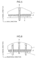
- Example 2 of the present invention as shown in Figs. 2 and 3 , an inner diameter size Rc in an axial end portion of a stator iron core 3 is made smaller than an inner diameter size Rd in the axial center portion. As a result, a flux leakage in both axial ends is prevented, and a reduction of output is prevented.
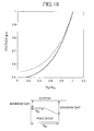
- the solid line shows the output voltage as a function of ratio W pt /W ps of the upper surface of diameter W pt and the lower surface diameter W ps of the pole shoe in case of the stator core 3 with same axial inner diameter at the axial end portion as at the axial center portion.
- the broken line shows the output voltage as a function of ratio Wp t/ W ps in case of a rotating machine with same air gap at the axial end portion as at the axial center portion.
- FIG. 2 shows a view in which the inner diameter of the stator iron core 3 is continuously changed by the axial positions, as shown in Fig. 3 , a portion allowing the inner diameter of the stator iron core to change in incremental steps may be provided.
- the rotor is also provided with a portion allowing the outer diameter of the rotor to change in incremental steps.
- Example 3 of the present invention will be shown in Figs. 4 to 6 .
- the present example shows one example of a rotor of a rotating machine according to the present invention
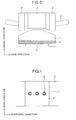
- Fig. 4 is a view of a magnetic pole seen from a radial direction
- Fig. 5 is a view seen from a peripheral direction
- Fig. 6 is a view seen from an axial direction, respectively.
- a pole shoe 1 and a permanent magnet 2 having a rectangular section are fastened to a pedestal 5 by a magnetic bolt 6.
- the pole shoe 1 has a smaller outer diameter in the axial center portion than in the axial end portion, thereby preventing displacement and peeling in axial both ends of the pole shoe due to a centrifugal force at the rotating time.
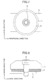
- Example 4 shown in Figs. 7 to 9 the shapes in radial section of a pole shoe 1 and a permanent magnet 2 are made circular, and a bolt hole is provided in each center in the axial direction, and the pole shoe and the permanent magnet are fastened and fixed by a bolt 6 from the radial direction.
- a bolt hole is provided in each center in the axial direction
- the pole shoe and the permanent magnet are fastened and fixed by a bolt 6 from the radial direction.
- stator iron core In an axial end portion of a stator iron core whose inner size is made smaller than in the axial center portion, incoming magnetic flux from a magnetic pole to the stator iron core in the axial direction is increased.
- stator made of steel sheets punched out from iron core is configured by an iron plate punched out from a steel band, eddy current loss by this magnetic flux arises local heating.
- Example 5 of the present invention a tooth 7 of the stator iron core 3 is provided with a slit 8 so as to reduce an eddy current loss, thereby preventing a local overheating.
- the slit may be plural.
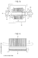
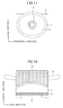
- Example 6 of the present invention as shown in Figs. 11 and 12 , both end portions of a stator iron core whose inner diameter is made smaller than in an axial center portion are configured by a stator iron core 10 formed by soft magnetic composites. As a result, eddy current loss is reduced, and a local overheating can be prevented.
- stator iron core When the stator iron core is configured by an iron plate punched out from a steel band, to change the inner diameter of the stator iron core, it is necessary to prepare a plurality of cutting dies, and this leads to an increase in the number of manufacturing man-hour.
- both end portions of the stator iron core different in the inner diameter are configured by the soft magnetic compound, so that the number of manufacturing man-hour can be reduced.
- Fig. 11 is a view in which both end portions of the stator iron core are all configured by the soft magnetic compound.
- a teeth portion only may be configured by the stator iron core 10 formed by the soft magnetic compound.
- the entire stator iron core may be configured by the soft magnetic compound.
- Example 7 of the present invention will be shown in Fig. 13.
- Fig. 13 shows a turbine generator system comprising a rotating machine of the present invention as a sub exciter.
- a generator shaft 11 is attached with a main exciter 14 and a sub exciter 15, and rotors of the main exciter and the sub exciter are configured to rotate accompanied with the rotation of the generator shaft.
- the sub exciter is attached to the opposite side of the main exciter seen from the axial direction. As a result, it is possible to shorten an axial length of the entire turbine generator.
- any of the rotating machines according to the present invention is provided as the sub exciter, thereby solving the above described problem. That is,
- the above makes the configuration of the present example possible, so that the deterioration of the turbine generator system can be prevented, and the life thereof can be prolonged. Furthermore, by performing the bolt fastening from the radial direction, the fabrication and maintenance can be easily performed.
- One aspect of the invention relates to a rotating machine, wherein permanent magnets (2) and pole shoes (1) holding the permanent magnet at an outer diameter side of the permanent magnet are provided for a rotor, and an outer diameter size (Ra) in an axial end portion of the pole shoe is made smaller than an outer diameter size (Rb) in an axial center portion thereof.
- bolt holes are provided in an axial center position of the pole shoes (1), and by bolts (6), the pole shoe and the permanent magnets are held by fastening from a radial direction.
- a radial section of any or both of the permanent magnet (2) and pole shoe (1) is made circular or oval.
- an outer diameter side of the rotor is provided with a stator iron core (10), and the entirety or a part of the stator iron core is formed by soft magnetic composites.
- the outer diameter side of the rotor is provided with a stator iron core (3), and an inner diameter size (Rc) in an axial end portion of the stator iron core is made smaller than an inner diameter size (Rd) in an axial center portion thereof.
- the outer diameter side of the rotor is provided with a stator iron core (3), and the inner diameter size is made smaller in incremental steps from the axial center portion to the axial end portion of the stator iron core.
- a portion (10) having an inner diameter size different from the inner diameter size in the axial center portion is formed by soft magnetic composites.
- an axial inner part of the portion (10) having the inner diameter size different from the inner diameter size in the axial center portion is formed by soft magnetic composites.
- the outer diameter size of the rotor is provided with the stator iron core (3), and a teeth portion (7) of the stator iron core (3) is provided with slits (8).
- a further aspect of the invention relates to a rotating machine, wherein a permanent magnet and a pole shoe holding the permanent magnet at an outer diameter side of the permanent magnet are provided for a stator, and moreover, the outer diameter side of the rotor is provided with the stator iron core, and an air gap formed between the rotor and the stator iron core, the air gap being at the axial center portion, is made smaller than an air gap size at both axial ends.
- a further aspect of the invention relates to a generating system, comprising a rotating machine as an exciter (14) or an sub exciter (15), wherein a permanent magnet (2) and a pole shoe (1) holding the permanent magnet at an outer diameter side of the permanent magnet are provided for a rotor, and an outer diameter size (Ra) in an axial end portion of the pole shoe is made smaller than an outer diameter size (Rb) in an axial center portion thereof.
Landscapes
- Engineering & Computer Science (AREA)
- Power Engineering (AREA)
- Iron Core Of Rotating Electric Machines (AREA)
- Permanent Field Magnets Of Synchronous Machinery (AREA)
- Permanent Magnet Type Synchronous Machine (AREA)
Applications Claiming Priority (2)
| Application Number | Priority Date | Filing Date | Title |
|---|---|---|---|
| JP2005371279A JP4696900B2 (ja) | 2005-12-26 | 2005-12-26 | 回転電機 |
| EP06025825.8A EP1801952B1 (de) | 2005-12-26 | 2006-12-13 | Drehende elektrische Maschine |
Related Parent Applications (2)
| Application Number | Title | Priority Date | Filing Date |
|---|---|---|---|
| EP06025825.8 Division | 2006-12-13 | ||
| EP06025825.8A Division EP1801952B1 (de) | 2005-12-26 | 2006-12-13 | Drehende elektrische Maschine |
Publications (3)
| Publication Number | Publication Date |
|---|---|
| EP2325979A2 true EP2325979A2 (de) | 2011-05-25 |
| EP2325979A3 EP2325979A3 (de) | 2011-06-08 |
| EP2325979B1 EP2325979B1 (de) | 2014-05-21 |
Family
ID=37671017
Family Applications (2)
| Application Number | Title | Priority Date | Filing Date |
|---|---|---|---|
| EP11156409.2A Active EP2325979B1 (de) | 2005-12-26 | 2006-12-13 | Drehende elektrische Maschine |
| EP06025825.8A Active EP1801952B1 (de) | 2005-12-26 | 2006-12-13 | Drehende elektrische Maschine |
Family Applications After (1)
| Application Number | Title | Priority Date | Filing Date |
|---|---|---|---|
| EP06025825.8A Active EP1801952B1 (de) | 2005-12-26 | 2006-12-13 | Drehende elektrische Maschine |
Country Status (3)
| Country | Link |
|---|---|
| US (1) | US7825559B2 (de) |
| EP (2) | EP2325979B1 (de) |
| JP (1) | JP4696900B2 (de) |
Families Citing this family (14)
| Publication number | Priority date | Publication date | Assignee | Title |
|---|---|---|---|---|
| GB2438443A (en) * | 2006-05-27 | 2007-11-28 | Converteam Ltd | Rotor magnet retaining arrangement suitable for low-speed large-diameter electrical generators |
| JP5030209B2 (ja) * | 2007-02-05 | 2012-09-19 | 東洋電機製造株式会社 | インホイールモータユニット |
| US20100038987A1 (en) * | 2008-08-14 | 2010-02-18 | Infinite Wind Energy LLC | Motors Having a Hyperbolic Cosine Curve Shape |
| US8653713B2 (en) * | 2009-04-07 | 2014-02-18 | Osaka Prefecture University Public Corporation | Magnetic circuit structure |
| FI121985B (fi) | 2009-05-27 | 2011-06-30 | Abb Oy | Järjestely magneetin kiinnittämiseksi roottoriin ja roottori |
| GB0910637D0 (en) | 2009-06-20 | 2009-08-05 | Univ Gent | Permanent magnet machine |
| FR2965988B1 (fr) * | 2010-10-07 | 2012-10-19 | Leroy Somer Moteurs | Rotor comportant des epanouissements polaires rapportes recouvrant les aimants et machine electrique tournante. |
| JP5363520B2 (ja) * | 2011-03-04 | 2013-12-11 | 株式会社日立産機システム | 永久磁石同期機 |
| JP6002020B2 (ja) * | 2011-12-20 | 2016-10-05 | 日本ピストンリング株式会社 | 回転電機 |
| DE102012220373A1 (de) * | 2012-04-17 | 2013-10-17 | Siemens Aktiengesellschaft | Polschuhanordnung für ein Maschinenelement einer elektrischen Maschine |
| JP6408766B2 (ja) * | 2014-01-28 | 2018-10-17 | 日本ピストンリング株式会社 | アキシャル立体ギャップ式回転電機 |
| FR3109249B1 (fr) * | 2020-04-10 | 2022-10-07 | Safran | Machine électrique synchrone à aimants permanents |
| JP2024030585A (ja) * | 2022-08-24 | 2024-03-07 | 日本ピストンリング株式会社 | アキシャルギャップ式回転電機 |
| WO2026049177A1 (ko) * | 2024-08-28 | 2026-03-05 | 에이치디현대일렉트릭 주식회사 | 영구자석 회전기의 회전자 |
Citations (1)
| Publication number | Priority date | Publication date | Assignee | Title |
|---|---|---|---|---|
| JPH0923599A (ja) | 1995-07-05 | 1997-01-21 | Otsupama Kogyo Kk | 磁石発電機の回転子 |
Family Cites Families (21)
| Publication number | Priority date | Publication date | Assignee | Title |
|---|---|---|---|---|
| DE167383C (de) * | ||||
| DE1030434B (de) | 1955-11-24 | 1958-05-22 | Ernst Massar Dr Ing | Dauermagneterregte Synchronmaschine mit ausgepraegten Polen |
| DE1488565A1 (de) * | 1965-06-29 | 1970-01-08 | Lloyd Dynamowerke Gmbh | Elektrische Maschine mit permanent-magnetischen Erregerpolen |
| JPS5111281B2 (de) * | 1972-03-29 | 1976-04-10 | ||
| JPS5395206A (en) * | 1977-02-01 | 1978-08-21 | Toshiba Corp | Stator core |
| DE3028269A1 (de) * | 1980-07-25 | 1982-02-11 | Siemens AG, 1000 Berlin und 8000 München | Permanentmagneterregte elektrische maschine |
| JPS589534A (ja) * | 1981-07-07 | 1983-01-19 | Hitachi Ltd | 回転電機の固定子 |
| DE4029271A1 (de) * | 1990-09-14 | 1992-03-19 | Magnet Motor Gmbh | Elektrische maschine |
| JPH05304799A (ja) * | 1992-04-24 | 1993-11-16 | Kokusan Denki Co Ltd | 発電装置 |
| JP2678884B2 (ja) * | 1994-05-23 | 1997-11-19 | 川崎重工業株式会社 | フライホイール用マグネット構造 |
| US5894183A (en) * | 1996-10-29 | 1999-04-13 | Caterpillar Inc. | Permanent magnet generator rotor |
| US6157109A (en) * | 1998-02-10 | 2000-12-05 | Reliance Electric Technologies, Llc | Dynamoelectric machine with ferromagnetic end winding ring |
| US6034462A (en) * | 1998-11-20 | 2000-03-07 | Woodward, Jr.; Richard C. | Cylindrical air gap electrical machines |
| JP2000316264A (ja) * | 1999-04-28 | 2000-11-14 | Fuji Electric Co Ltd | 同期機 |
| WO2004004092A1 (ja) * | 2002-07-01 | 2004-01-08 | Toyoda Koki Kabushiki Kaisha | 回転電機 |
| US6903485B2 (en) * | 2003-05-21 | 2005-06-07 | Visteon Global Technologies, Inc. | Claw-pole alternator with non-uniform air gap |
| JP2004364368A (ja) * | 2003-06-03 | 2004-12-24 | Toyota Motor Corp | スイッチド・リラクタンス・モータ |
| JP2005160203A (ja) * | 2003-11-26 | 2005-06-16 | Toyota Motor Corp | スイッチドリラクタンスモータ |
| US6864612B1 (en) * | 2004-03-09 | 2005-03-08 | Kazuhiko Gotoh | Iron core for electric motor and electric generator |
| JP2005304202A (ja) * | 2004-04-13 | 2005-10-27 | Tokushu Denso Kk | 回転機用鉄心 |
| JP4677806B2 (ja) * | 2005-03-25 | 2011-04-27 | 株式会社日立製作所 | 発電機及び発電システム |
-
2005
- 2005-12-26 JP JP2005371279A patent/JP4696900B2/ja not_active Expired - Lifetime
-
2006
- 2006-12-13 EP EP11156409.2A patent/EP2325979B1/de active Active
- 2006-12-13 EP EP06025825.8A patent/EP1801952B1/de active Active
- 2006-12-26 US US11/644,841 patent/US7825559B2/en active Active
Patent Citations (1)
| Publication number | Priority date | Publication date | Assignee | Title |
|---|---|---|---|---|
| JPH0923599A (ja) | 1995-07-05 | 1997-01-21 | Otsupama Kogyo Kk | 磁石発電機の回転子 |
Also Published As
| Publication number | Publication date |
|---|---|
| US20070145848A1 (en) | 2007-06-28 |
| EP1801952B1 (de) | 2013-06-12 |
| EP1801952A3 (de) | 2011-02-23 |
| US7825559B2 (en) | 2010-11-02 |
| EP2325979A3 (de) | 2011-06-08 |
| JP2007174847A (ja) | 2007-07-05 |
| EP1801952A2 (de) | 2007-06-27 |
| EP2325979B1 (de) | 2014-05-21 |
| JP4696900B2 (ja) | 2011-06-08 |
Similar Documents
| Publication | Publication Date | Title |
|---|---|---|
| EP2325979B1 (de) | Drehende elektrische Maschine | |
| US6008559A (en) | Motor using a rotor including an interior permanent magnet | |
| EP1892814A1 (de) | Motor des typs mit doppelrotor | |
| JP4720982B2 (ja) | アキシャルエアギャップ型電動機 | |
| US7687959B1 (en) | Brushless a-c motor | |
| JP2012120326A (ja) | 磁石埋め込み型回転子、電動機及び電動機の組立方法 | |
| JP2011024291A (ja) | ステータコア及びアキシャルギャップモータ | |
| US20130061457A1 (en) | Method of forming a rotor lamination assembly | |
| CA2499164A1 (en) | An electrical motor/generator having a number of stator pole cores being larger than a number of rotor pole shoes | |
| JP5573109B2 (ja) | 永久磁石式電動機の回転子 | |
| JP2018137924A (ja) | 回転電機のロータ | |
| US20060071576A1 (en) | Flat board type brushless dc motor | |
| JP4677806B2 (ja) | 発電機及び発電システム | |
| US6744163B2 (en) | Vibration type brushless motor | |
| US6239527B1 (en) | Non-circular field winding enclosure | |
| JP2001268824A (ja) | コンプレッサー | |
| EP2372106B1 (de) | Turbogenerator | |
| JP4604565B2 (ja) | 回転子、およびこれを備えた回転電機 | |
| JP2005269831A (ja) | ブラシレスdcモータ | |
| US7554229B2 (en) | Stator structure of motor | |
| JP6752159B2 (ja) | アキシャルギャップ型回転電機 | |
| JP4704883B2 (ja) | 永久磁石式回転電機および円筒型リニアモータ | |
| KR20240071562A (ko) | 할박배열구조 모터의 자석 설치구조 및 설치방법 | |
| EP1585210B1 (de) | Läuferaufbau | |
| JPH11299145A (ja) | 電動機のロータ |
Legal Events
| Date | Code | Title | Description |
|---|---|---|---|
| PUAI | Public reference made under article 153(3) epc to a published international application that has entered the european phase |
Free format text: ORIGINAL CODE: 0009012 |
|
| PUAL | Search report despatched |
Free format text: ORIGINAL CODE: 0009013 |
|
| AC | Divisional application: reference to earlier application |
Ref document number: 1801952 Country of ref document: EP Kind code of ref document: P |
|
| AK | Designated contracting states |
Kind code of ref document: A2 Designated state(s): AT BE BG CH CY CZ DE DK EE ES FI FR GB GR HU IE IS IT LI LT LU LV MC NL PL PT RO SE SI SK TR |
|
| AX | Request for extension of the european patent |
Extension state: AL BA HR MK RS |
|
| AK | Designated contracting states |
Kind code of ref document: A3 Designated state(s): AT BE BG CH CY CZ DE DK EE ES FI FR GB GR HU IE IS IT LI LT LU LV MC NL PL PT RO SE SI SK TR |
|
| AX | Request for extension of the european patent |
Extension state: AL BA HR MK RS |
|
| 17P | Request for examination filed |
Effective date: 20110704 |
|
| RBV | Designated contracting states (corrected) |
Designated state(s): DE FR GB |
|
| 17Q | First examination report despatched |
Effective date: 20121106 |
|
| REG | Reference to a national code |
Ref country code: DE Ref legal event code: R079 Ref document number: 602006041723 Country of ref document: DE Free format text: PREVIOUS MAIN CLASS: H02K0001270000 Ipc: H02K0001060000 |
|
| RIC1 | Information provided on ipc code assigned before grant |
Ipc: H02K 1/06 20060101AFI20130920BHEP Ipc: H02K 1/14 20060101ALI20130920BHEP Ipc: H02K 1/27 20060101ALI20130920BHEP Ipc: H02K 1/16 20060101ALI20130920BHEP Ipc: H02K 3/42 20060101ALI20130920BHEP |
|
| GRAP | Despatch of communication of intention to grant a patent |
Free format text: ORIGINAL CODE: EPIDOSNIGR1 |
|
| INTG | Intention to grant announced |
Effective date: 20131203 |
|
| GRAS | Grant fee paid |
Free format text: ORIGINAL CODE: EPIDOSNIGR3 |
|
| GRAA | (expected) grant |
Free format text: ORIGINAL CODE: 0009210 |
|
| RAP1 | Party data changed (applicant data changed or rights of an application transferred) |
Owner name: HITACHI, LTD. |
|
| RIN1 | Information on inventor provided before grant (corrected) |
Inventor name: KIMURA, MAMORU Inventor name: TAKAHASHI, KAZUHIKO Inventor name: NAKAHARA, AKIHITO Inventor name: SEMBA, AKITOMI |
|
| AC | Divisional application: reference to earlier application |
Ref document number: 1801952 Country of ref document: EP Kind code of ref document: P |
|
| AK | Designated contracting states |
Kind code of ref document: B1 Designated state(s): DE FR GB |
|
| REG | Reference to a national code |
Ref country code: GB Ref legal event code: FG4D |
|
| REG | Reference to a national code |
Ref country code: DE Ref legal event code: R096 Ref document number: 602006041723 Country of ref document: DE Effective date: 20140710 |
|
| REG | Reference to a national code |
Ref country code: DE Ref legal event code: R082 Ref document number: 602006041723 Country of ref document: DE Representative=s name: BEETZ & PARTNER PATENT- UND RECHTSANWAELTE, DE |
|
| RAP2 | Party data changed (patent owner data changed or rights of a patent transferred) |
Owner name: MITSUBISHI HITACHI POWER SYSTEMS, LTD. |
|
| REG | Reference to a national code |
Ref country code: GB Ref legal event code: 732E Free format text: REGISTERED BETWEEN 20140925 AND 20141001 |
|
| REG | Reference to a national code |
Ref country code: DE Ref legal event code: R082 Ref document number: 602006041723 Country of ref document: DE Representative=s name: BEETZ & PARTNER PATENT- UND RECHTSANWAELTE, DE Effective date: 20140923 Ref country code: DE Ref legal event code: R081 Ref document number: 602006041723 Country of ref document: DE Owner name: MITSUBISHI HITACHI POWER SYSTEMS, LTD., YOKOHA, JP Free format text: FORMER OWNER: HITACHI, LTD., TOKYO, JP Effective date: 20140923 Ref country code: DE Ref legal event code: R082 Ref document number: 602006041723 Country of ref document: DE Representative=s name: BEETZ & PARTNER MBB PATENT- UND RECHTSANWAELTE, DE Effective date: 20140923 Ref country code: DE Ref legal event code: R082 Ref document number: 602006041723 Country of ref document: DE Representative=s name: BEETZ & PARTNER MBB, DE Effective date: 20140923 Ref country code: DE Ref legal event code: R082 Ref document number: 602006041723 Country of ref document: DE Representative=s name: BEETZ & PARTNER MBB PATENTANWAELTE, DE Effective date: 20140923 |
|
| REG | Reference to a national code |
Ref country code: DE Ref legal event code: R097 Ref document number: 602006041723 Country of ref document: DE |
|
| PLBE | No opposition filed within time limit |
Free format text: ORIGINAL CODE: 0009261 |
|
| STAA | Information on the status of an ep patent application or granted ep patent |
Free format text: STATUS: NO OPPOSITION FILED WITHIN TIME LIMIT |
|
| RAP2 | Party data changed (patent owner data changed or rights of a patent transferred) |
Owner name: MITSUBISHI HITACHI POWER SYSTEMS, LTD. |
|
| 26N | No opposition filed |
Effective date: 20150224 |
|
| REG | Reference to a national code |
Ref country code: DE Ref legal event code: R097 Ref document number: 602006041723 Country of ref document: DE Effective date: 20150224 |
|
| REG | Reference to a national code |
Ref country code: FR Ref legal event code: PLFP Year of fee payment: 10 |
|
| REG | Reference to a national code |
Ref country code: FR Ref legal event code: PLFP Year of fee payment: 11 |
|
| REG | Reference to a national code |
Ref country code: FR Ref legal event code: PLFP Year of fee payment: 12 |
|
| REG | Reference to a national code |
Ref country code: DE Ref legal event code: R081 Ref document number: 602006041723 Country of ref document: DE Owner name: MITSUBISHI HEAVY INDUSTRIES, LTD., JP Free format text: FORMER OWNER: MITSUBISHI HITACHI POWER SYSTEMS, LTD., YOKOHAMA, KANAGAWA, JP Ref country code: DE Ref legal event code: R081 Ref document number: 602006041723 Country of ref document: DE Owner name: MITSUBISHI GENERATOR CO., LTD., KOBE-SHI, JP Free format text: FORMER OWNER: MITSUBISHI HITACHI POWER SYSTEMS, LTD., YOKOHAMA, KANAGAWA, JP Ref country code: DE Ref legal event code: R082 Ref document number: 602006041723 Country of ref document: DE Representative=s name: BEETZ & PARTNER MBB PATENTANWAELTE, DE Ref country code: DE Ref legal event code: R081 Ref document number: 602006041723 Country of ref document: DE Owner name: MITSUBISHI POWER, LTD., JP Free format text: FORMER OWNER: MITSUBISHI HITACHI POWER SYSTEMS, LTD., YOKOHAMA, KANAGAWA, JP |
|
| REG | Reference to a national code |
Ref country code: DE Ref legal event code: R081 Ref document number: 602006041723 Country of ref document: DE Owner name: MITSUBISHI HEAVY INDUSTRIES, LTD., JP Free format text: FORMER OWNER: MITSUBISHI POWER, LTD., YOKOHAMA, JP Ref country code: DE Ref legal event code: R081 Ref document number: 602006041723 Country of ref document: DE Owner name: MITSUBISHI GENERATOR CO., LTD., KOBE-SHI, JP Free format text: FORMER OWNER: MITSUBISHI POWER, LTD., YOKOHAMA, JP |
|
| REG | Reference to a national code |
Ref country code: GB Ref legal event code: 732E Free format text: REGISTERED BETWEEN 20230907 AND 20230913 |
|
| REG | Reference to a national code |
Ref country code: DE Ref legal event code: R081 Ref document number: 602006041723 Country of ref document: DE Owner name: MITSUBISHI GENERATOR CO., LTD., KOBE-SHI, JP Free format text: FORMER OWNER: MITSUBISHI HEAVY INDUSTRIES, LTD., TOKYO, JP |
|
| REG | Reference to a national code |
Ref country code: GB Ref legal event code: 732E Free format text: REGISTERED BETWEEN 20241107 AND 20241113 |
|
| PGFP | Annual fee paid to national office [announced via postgrant information from national office to epo] |
Ref country code: DE Payment date: 20251028 Year of fee payment: 20 |
|
| PGFP | Annual fee paid to national office [announced via postgrant information from national office to epo] |
Ref country code: GB Payment date: 20251030 Year of fee payment: 20 |
|
| PGFP | Annual fee paid to national office [announced via postgrant information from national office to epo] |
Ref country code: FR Payment date: 20251117 Year of fee payment: 20 |