EP2325566B1 - Gargerät mit einem garraum und einschubgittern - Google Patents
Gargerät mit einem garraum und einschubgittern Download PDFInfo
- Publication number
- EP2325566B1 EP2325566B1 EP10190171.8A EP10190171A EP2325566B1 EP 2325566 B1 EP2325566 B1 EP 2325566B1 EP 10190171 A EP10190171 A EP 10190171A EP 2325566 B1 EP2325566 B1 EP 2325566B1
- Authority
- EP
- European Patent Office
- Prior art keywords
- slide
- side wall
- folded
- grid
- cooking
- Prior art date
- Legal status (The legal status is an assumption and is not a legal conclusion. Google has not performed a legal analysis and makes no representation as to the accuracy of the status listed.)
- Active
Links
Images

Classifications
-
- F—MECHANICAL ENGINEERING; LIGHTING; HEATING; WEAPONS; BLASTING
- F24—HEATING; RANGES; VENTILATING
- F24C—DOMESTIC STOVES OR RANGES ; DETAILS OF DOMESTIC STOVES OR RANGES, OF GENERAL APPLICATION
- F24C15/00—Details
- F24C15/16—Shelves, racks or trays inside ovens; Supports therefor
-
- F—MECHANICAL ENGINEERING; LIGHTING; HEATING; WEAPONS; BLASTING
- F24—HEATING; RANGES; VENTILATING
- F24C—DOMESTIC STOVES OR RANGES ; DETAILS OF DOMESTIC STOVES OR RANGES, OF GENERAL APPLICATION
- F24C15/00—Details
- F24C15/16—Shelves, racks or trays inside ovens; Supports therefor
- F24C15/168—Shelves, racks or trays inside ovens; Supports therefor with telescopic rail systems
Definitions
- the invention relates to a cooking appliance with a cooking space and two slide-in grids which are arranged on a respective side wall of the cooking space.
- Cooking devices with a pull-out system are also known, in which a food support can be moved into the cooking space with the pull-out system and can be moved out of the cooking space.
- the pull-out system can e.g. Include telescopic rails.
- a general problem with the use of food carriers is that they have to be removed from the cooking space and stowed when the cooking appliance is in operation when they are not needed to carry the food to be cooked.
- a stove is known with a door mounted on hinges on the stove housing and with receiving grids for the sliding movable storage of insert plates, insert grids or similar inserts.
- the receiving grids are designed as a sliding movable support device with a connecting element arranged between the receiving grids and can be pivoted in one embodiment from a horizontal to a vertical position.
- a cooking device with a cooking space and two slide-in grids, which can be arranged on a respective side wall of the cooking space, the slide-in grids each being movable around at least one joint and being designed to fold up, essentially to one, in the cooking space Side wall of the cooking space parallel position and a folded down, substantially horizontal position.
- the slide-in grid acts as a conventional slide-in grid for receiving separate food carriers, in the folded down position it functions as a grate.
- the object can also be achieved by a grate or grate section which can be moved around at least one joint and which is set up in the cooking space to have a folded-up position (as an insert grid) and a folded-down position which is essentially parallel to a side wall of the cooking space. essentially horizontal position (as a conventional grate).
- the slide-in grid is connected to at least one wall of the cooking space via the at least one joint.
- the slide-in grid is consequently permanently arranged in the cooking space. This arrangement is particularly easy to use.
- At least one wall of the cooking space has at least one projection, which serves as a stop for the slide-in grid in the folded-down position. This prevents the slide-in grid from folding over the folded-down, essentially horizontal position, so that the food to be cooked can rest safely on the slide-in grid without slipping.
- the at least one joint has a pin running in a longitudinal groove.
- the slide-in grid can fix itself in the folded-up, essentially vertical position, without the need for a dedicated fixing means. Rather, the side wall of the cooking space serves as a stop, which prevents the rack from folding down.
- the slide-in grille can be brought into a swiveling position simply by pulling it up and then folded down into the horizontal position. Conversely, the slide-in grille can be folded up from the horizontal position around the joint and then simply slide down into the fixed vertical position. In the vertical, fixed position, the pin is located at an inner end of the longitudinal groove, in the pivotable position at the other, outer end of the longitudinal groove.
- the slide-in grid can be fixed in the folded-up position by means of at least one releasable fixing means, in particular locking means. This can also prevent accidental folding down.
- the slide-in grille which is pivotally attached to the side wall, it is permanently arranged on the respective side wall of the cooking space.
- the two slide-in grids can be fixed to one another by means of at least one releasable fixing means.
- the insertion grids can be pivoted considerably beyond the horizontal without a stop or in addition to a stop.
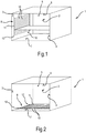
- Fig. 1 shows a cooking device in the form of an oven 1, for example an oven or a microwave oven, with a cooking space 2.
- the cooking space 2 is delimited by corresponding cooking space walls, namely a left side wall 3, a right side wall 4, a rear wall 5, a ceiling 6 and one Floor 7.
- a front wall of the cooking space is formed by an oven door, not shown here.
- the first slide-in grille 8 shown is in a folded-up, essentially vertical position and lying parallel to the left side wall 3.
- a plurality of horizontally extending bars 10 define the possible contact surfaces and consequently insertion levels for food carriers.
- the bars 10 are held together by support struts 11 running perpendicular to them.
- the two outermost support struts 11 are connected at their lower end to the left side wall 3 via a joint 12.
- a releasable fixation of the insert grid 8 in the folded-up position can be achieved, for example, by designing the joint and / or at least one dedicated one Fixing or locking means happen, for example a snap hook.
- a snap hook that can be easily released by a user can be present on the respective side wall, in which one of the grating bars 10 or the support struts 11 can snap into place.
- the snap hook is preferably arranged near the loading opening or oven door.
- Fig. 2 shows the oven 1 with the two shelf grids 8 in a folded down position.
- the two slide-in grids 8 lie essentially horizontally and now, analogously to a food support in the form of a wire shelf, form a support surface for food to be cooked.
- the insert grids 8 thus serve as a grating without a user having to have a separate grating. This saving on the separate grating also has a positive effect on an energy balance.
- the two slide-in grids 8 can rest on the floor 7 in the folded-down position.
- the slide-in grids 8 can be in the folded-down position spaced from the floor 7 and then rest on a stop so as not to be inclined beyond the horizontal.
- The, respective or common, stop can e.g. be formed as a protrusion into the cooking space 2 of one of the cooking space walls 3, 4, 5, 7, preferably in a rear area of the cooking space, e.g. a protrusion protruding from the rear wall 2.
- Fig. 3 shows a section of the insert grid 8 fastened to the left side wall 3 in the folded-up position in a region of the joint 12.
- the joint 12 is formed by the insert grid 8 and the side wall 3. More precisely, the support struts 11, only one of which is shown here, each have a longitudinal groove 13 at their lower ends.
- a pin 14 lying horizontally and parallel to the side wall 3 runs in the longitudinal groove and is fastened to the side wall 3 via two retaining tabs 15.
- the parts 14, 15 of the hinge 13 assigned to the side wall 3 are shown here with dots.
- the shelf 8 rests on the pins 14 due to its weight, so that rotation of the shelf 8 into the cooking space 2 is blocked by the side wall 3 as the stop.
- the play of the rotation is determined, among other things, by a distance between the insert grid 8 and the side wall 3.
- Fig. 4 shows a section of the shelf 8 now in the folded position.
- the slide-in grid 8 is pulled up and consequently the pin 14 in the longitudinal groove 13 is moved to the other end and then pivoted into the cooking space 2.
- a rear support strut 11 comes to rest on a projection 16 serving as a stop and extending forward from the rear wall 5.
Landscapes
- Engineering & Computer Science (AREA)
- Chemical & Material Sciences (AREA)
- Combustion & Propulsion (AREA)
- Mechanical Engineering (AREA)
- General Engineering & Computer Science (AREA)
- Baking, Grill, Roasting (AREA)
Description
- Die Erfindung betrifft ein ein Gargerät mit einem Garraum und zwei Einschubgittern, welche an einer jeweiligen Seitenwand des Garraums angeordnet sind.
- Bisher weisen viele Gargeräte an ihren Seitenwänden Einschubgitter auf, in welche auf mehreren Einschubebenen Gargutträger wie Einschubroste usw. eingeschoben werden können. Bei dieser Anordnung wird an den Seiten durch das Einschubgitter und einen entsprechenden Auflagebereich Platz für eine Anordnung von Gargut verloren. Zudem verschlechtern die Gargutträger aufgrund eines Energieaufwands zu Ihrer Herstellung einen Effizienzklassenwert.
- Auch sind Gargeräte mit einem Auszugsystem bekannt, bei dem ein Gargutträger mit dem Auszugsystem in den Garraum eingefahren und aus dem Garraum ausgefahren werden kann. Das Auszugsystem kann z.B. Teleskopschienen umfassen.
- Ein allgemeines Problem bei der Verwendung von Gargutträgern ist, dass sie bei einem Betrieb des Gargeräts aus dem Garraum entfernt und verstaut werden müssen, wenn sie nicht zum Tragen von Gargut benötigt werden.
- Ausschließlich für Auszugssysteme ist aus
DE 4014823 A1 ist ein Herd mit einer über Scharniere am Herdgehäuse gelagerten Tür und mit Aufnahmegittern zur schiebbeweglichen Lagerung von Einschubblechen, Einsatzrosten oder ähnlichen Einschüben bekannt. Die Aufnahmegitter sind als schiebbewegliche Tragvorrichtung mit einem zwischen den Aufnahmegittern angeordneten Verbindungselement ausgebildet und können in einer Ausgestaltung aus einer waagerechten in eine senkrechte Position geschwenkt werden. - Aus
JP S54 28150 U - Es ist die Aufgabe der vorliegenden Erfindung eine Möglichkeit zum Ablegen von Gargut in einem Garraum eines Gargeräts zu schaffen, welche für einen Nutzer bequem und vielseitig nutzbar ist.
- Diese Aufgabe wird gemäß den Merkmalen des unabhängigen Anspruchs 1 gelöst. Bevorzugte Ausführungsformen sind insbesondere den abhängigen Ansprüchen entnehmbar.
- Die Aufgabe wird gelöst durch ein Gargerät mit einem Garraum und zwei Einschubgittern, welche an einer jeweiligen Seitenwand des Garraums anordenbar sind, wobei die Einschubgitter jeweils um mindestens ein Gelenk herum beweglich sind und dazu eingerichtet sind, in dem Garraum eine hochgeklappte, im Wesentlichen zu einer Seitenwand des Garraums parallele Stellung und eine heruntergeklappte, im Wesentlichen horizontale Stellung einzunehmen. In der hochgeklappten im Wesentlichen senkrechten Stellung nimmt das Einschubgitter die Funktion eines herkömmlichen Einschubgitters zur Aufnahme von separaten Gargutträgern wahr, in der heruntergeklappten Stellung die Funktion eines Rosts. In anderen Worten kann die Aufgabe auch gelöst werden durch einen um mindestens ein Gelenk herum beweglichen Rost oder Rostabschnitt, welcher dazu eingerichtet ist, in dem Garraum eine hochgeklappte, im Wesentlichen zu einer Seitenwand des Garraums parallele Stellung (als ein Einschubgitter) und eine heruntergeklappte, im Wesentlichen horizontale Stellung (als ein herkömmlicher Rost) einzunehmen.
- In der heruntergeklappten Stellung braucht seitlich kein Platz für ein separates Einschubgitter mehr vorgesehen zu werden, so dass das Einschubgitter als Rost eine größere Nutzfläche aufweist als ein herkömmlicher Rost. Ein Benutzer braucht zudem für viele Anwendungen keinen separaten Einschubrost mehr zu verwenden, was eine Benutzung bequemer macht. Auch kann Energie zur Herstellung eines separaten Rosts eingespart werden.
- Ferner ist das Einschubgitter über das mindestens eine Gelenk mit mindestens einer Wand des Garraums verbunden. Das Einschubgitter ist folglich dauernd in dem Garraum angeordnet. Diese Anordnung ist besonders einfach anwendbar.
- Es ist eine besondere Ausgestaltung, dass mindestens eine Wand des Garraums mindestens einen Vorsprung aufweist, welcher als ein Anschlag für das Einschubgitter in der heruntergeklappten Stellung dient. Dadurch wird ein Umklappen des Einschubgitters über die heruntergeklappte, im Wesentlichen horizontale Stellung hinaus verhindert, so dass das Gargut sicher und ohne zu rutschen auf dem Einschubgitter liegen kann.
- Es ist zudem eine Ausgestaltung, dass das mindestens eine Gelenk einen in einer Längsnut laufenden Stift aufweist. Dadurch kann das Einschubgitter sich selbst in der hochgeklappten, im Wesentlichen senkrechten Stellung fixieren, und zwar ohne eines dediziertes Fixiermittel zu benötigen. Vielmehr dient die Seitenwand des Garraums als ein Anschlag, welcher ein Herunterklappen des Einschubgitters verhindert. Das Einschubgitter kann einfach durch ein Hochziehen in eine verschwenkbare Lage gebracht und dann in die horizontale Stellung heruntergeklappt werden. Umgekehrt kann das Einschubgitter aus der horizontalen Stellung um das Gelenk hochgeklappt und dann einfach in die fixierte senkrechte Stellung heruntergleiten. In der senkrechten fixierten Stellung befindet sich der Stift an einem weiter Innen liegenden Ende der Längsnut, in der verschwenkbaren Lage an dem anderen, weiter Außen liegenden Ende der Längsnut.
- Es ist ferner eine Ausgestaltung, dass das Einschubgitter in der hochgeklappten Stellung mittels mindestens eines lösbaren Fixiermittels, insbesondere Rastmittels, fixierbar ist. Dadurch kann ebenfalls ein versehentliches Herunterklappen verhindert werden.
- Bei dem an der Seitenwand verschwenkbar befestigten Einschubgitter ist dieses permanent an der jeweiligen Seitenwand des Garraums angeordnet.
- Es ist eine Weiterbildung, dass die beiden Einschubgitter mittels mindestens eines lösbaren Fixiermittels miteinander fixierbar sind. Dadurch kann ein Überschwenken der Einschubgitter erheblich über die Horizontale auch ohne einen Anschlag oder zusätzlich zu einem Anschlag gewährleistet werden.
- In den folgenden Figuren wird die Erfindung anhand eines Ausführungsbeispiels schematisch genauer beschrieben. Dabei können zur Übersichtlichkeit gleiche oder gleichwirkende Elemente mit gleichen Bezugszeichen versehen sein.
- Fig.1
- zeigt in Ansicht von schräg vorne einen Ofen mit einem Einschubgitter gemäß einer ersten erfinderischen Ausführungsform mit dem Einschubgitter in einer hochgeklappten Stellung;
- Fig.2
- zeigt den Ofen aus
Fig.1 mit Einschubgittern in einer heruntergeklappten Stellung; - Fig.3
- zeigt in Seitenansicht einen Ausschnitt des Einschubgitters gemäß der ersten erfinderischen Ausführungsform in der hochgeklappten Stellung in einem Bereich einer Gelenkverbindung mit einer Garraumwand; und
- Fig.4
- zeigt in Seitenansicht einen Ausschnitt des Einschubgitters gemäß der ersten erfinderischen Ausführungsform in der heruntergeklappten Stellung in einem Bereich einer Gelenkverbindung mit einer Garraumwand.
-
Fig.1 zeigt ein Gargerät in Form eines Ofens 1, z.B. eines Backofens oder eines Mikrowellenofens, mit einem Garraum 2. Der Garraum 2 wird durch entsprechende Garraumwände begrenzt, nämlich eine linke Seitenwand 3, eine rechte Seitenwand 4, eine Rückwand 5, eine Decke 6 und einen Boden 7. Eine vordere Garraumwand wird durch eine hier nicht abgebildete Ofentür gebildet. An den beiden Seitenwänden 3,4 ist jeweils ein Einschubgitter 8 angebracht, in welches hier auf einer Einschubebene ein Gargutträger in Form eines Backblechs 9 eingeschoben ist. - Das gezeigte erste Einschubgitter 8 befindet sich in einer hochgeklappten, im Wesentlichen senkrecht stehenden und parallel zu der linken Seitenwand 3 liegenden Stellung. Dabei definieren mehrere waagerecht verlaufende Gitterstäbe 10 die möglichen Auflageflächen und folglich Einschubebenen für Gargutträger. Die Gitterstäbe 10 werden durch senkrecht zu ihnen verlaufende Stützstreben 11 zusammengehalten. Die zwei äußersten Stützstreben 11 sind an ihrem unteren Ende über ein Gelenk 12 mit der linken Seitenwand 3 verbunden. Spiegelbildlich befindet sich ein zweites Einschubgitter an der rechten Seitenwand 4, so dass die beiden Einschubgitter den oder die Gargutträger halten können.
- Eine lösbare Fixierung des Einschubgitters 8 in der hochgeklappten Stellung kann beispielsweise über eine Ausgestaltung des Gelenks und/oder mindestens ein dediziertes Fixier- oder Arretierungsmittel geschehen, z.B. einen Schnapphaken. Beispielsweise kann an der jeweiligen Seitenwand ein durch einen Benutzer einfach lösbarer Schnapphaken vorhanden sein, in welchen einer der Gitterstäbe 10 oder der Stützstreben 11 einrasten kann. Für eine einfache Bedienung ist der Schnapphaken vorzugsweise nahe der Beschickungsöffnung oder Ofentür angeordnet.
-
Fig.2 zeigt den Ofen 1 mit den beiden Einschubgittern 8 in einer heruntergeklappten Stellung. In der heruntergeklappten Stellung liegen die beiden Einschubgitter 8 im Wesentlichen horizontal und bilden nun analog zu einem Gargutträger in Form eines Gitterrosts eine Auflagefläche für Gargut. Die Einschubgittern 8 dienen in ihrer heruntergeklappten Stellung somit als ein Gitterrost, ohne dass ein Benutzer einen separaten Gitterrost vorzuhalten braucht. Diese Einsparung des separaten Gitterrosts wirkt sich auch positiv auf eine Energiebilanz auf. - Die beiden Einschubgitter 8 können in der heruntergeklappten Stellung auf dem Boden 7 aufliegen. Alternativ können sich die Einschubgitter 8 in der heruntergeklappten Stellung beabstandet von dem Boden 7 befinden und dann auf einem Anschlag aufliegen, um nicht über die Horizontale hinaus schräg zu stehen. Der, jeweilige oder gemeinsame, Anschlag kann z.B. als ein in den Garraum 2 ragender Vorsprung einer der Garraumwände 3,4,5,7 ausgebildet sein, vorzugsweise in einem hinteren Bereich des Garraums, z.B. ein aus der Rückwand 2 ragender Vorsprung.
-
Fig.3 zeigt einen Ausschnitt des an der linken Seitenwand 3 befestigten Einschubgitters 8 in der hochgeklappten Stellung in einem Bereich des Gelenks 12. Das Gelenk 12 wird durch das Einschubgitter 8 und die Seitenwand 3 gebildet. Genauer gesagt weisen die Stützstreben 11, von denen hier nur eine dargestellt ist, an ihren unteren Enden jeweils eine Längsnut 13 auf. In der Längsnut läuft ein waagerecht und parallel zu der Seitenwand 3 liegender Stift 14, welcher über zwei Haltelaschen 15 an der Seitenwand 3 befestigt ist. Die der Seitenwand 3 zugeordneten Teile 14,15 des Scharniers 13 sind hier gepunktet eingezeichnet. In der hochgeklappten Stellung liegt das Einschubgitter 8 aufgrund seines Gewichts auf den Stiften 14 auf, so dass eine Verdrehung des Einschubgitters 8 in den Garraum 2 hinein durch die Seitenwand 3 als dem Anschlag blockiert wird. Dabei wird das Spiel der Verdrehung unter anderem durch einen Abstand des Einschubgitters 8 von der Seitenwand 3 bestimmt. -
Fig.4 zeigt einen Ausschnitt des Einschubgitters 8 nun in der heruntergeklappten Stellung. Zur Überführung aus der hochgeklappten (senkrechten) Stellung in die heruntergeklappte (waagerechte) Stellung wird das Einschubgitter 8 hochgezogen und folglich der Stift 14 in der Längsnut 13 an das andere Ende verschoben und dann in die den Garraum 2 verschwenkt. Eine hintere Stützstrebe 11 kommt auf einem als Anschlag dienendem, sich aus der Rückwand 5 nach vorne erstreckenden Vorsprung 16 zu liegen. - Selbstverständlich ist die vorliegende Erfindung nicht auf die gezeigten Ausführungsbeispiele beschränkt.
-
- 1
- Ofen
- 2
- Garraum
- 3
- linke Seitenwand
- 4
- rechte Seitenwand
- 5
- Rückwand
- 6
- Decke
- 7
- Boden
- 8
- Einschubgitter
- 9
- Backblech
- 10
- Gitterstab
- 11
- Stützstrebe
- 12
- Gelenk
- 13
- Längsnut
- 14
- Stift
- 15
- Haltelasche
- 16
- Vorsprung
Claims (8)
- Gargerät (1) mit einem Garraum (2) und mindestens zwei Einschubgittern (8), welche- an einer jeweiligen Seitenwand (3, 4) des Garraums (2) anordenbar sind,- dazu eingerichtet sind, in dem Garraum (2) eine hochgeklappte, im Wesentlichen zu der jeweiligen Seitenwand (3, 4) parallele Stellung und eine heruntergeklappte, im Wesentlichen horizontale Stellung einzunehmen und- in ihrer heruntergeklappten Stellung einen Gitterrost bilden,
dadurch gekennzeichnet, dass- die Einschubgitter (8) an einer jeweiligen Seitenwand (3, 4) des Garraums (2) mittels mindestens eines Gelenks (12), um das herum sie verschwenkbar sind, befestigt sind. - Gargerät (1) nach Anspruch 1, dadurch gekennzeichnet, dass eine Rückwand (5) des Garraums (2) mindestens einen Vorsprung (16) aufweist, welcher als ein Anschlag für das Einschubgitter (8) in der heruntergeklappten Stellung dient.
- Gargerät (1) nach einem der vorhergehenden Ansprüche, dadurch gekennzeichnet, dass das mindestens eine Gelenk (12) einen in einer Längsnut (13) laufenden Stift (14) aufweist, wobei die jeweilige Seitenwand (3, 4) dann, wenn das Einschubgitter (8) in der hochgeklappten Stellung fixiert ist, als ein Anschlag dient, welcher ein Herunterklappen des Einschubgitters (8) verhindert.
- Gargerät (1) nach einem der vorhergehenden Ansprüche, dadurch gekennzeichnet, dass das Einschubgitter in der hochgeklappten Stellung mittels mindestens eines lösbaren Fixiermittels, insbesondere Rastmittels, fixierbar ist.
- Gargerät (1) nach einem der vorhergehenden Ansprüche, dadurch gekennzeichnet, dass die beiden Einschubgitter (8) mittels mindestens eines lösbaren Fixiermittels miteinander fixierbar sind.
- Gargerät (1) nach einem der vorhergehenden Ansprüche, dadurch gekennzeichnet, dass das Gelenk (12) durch das Einschubgitter (8) und die jeweilige Seitenwand (3, 4) gebildet ist.
- Gargerät (1) nach Anspruch 6, dadurch gekennzeichnet, dass das Einschubgitter (8) mehrere waagerecht verlaufende Gitterstäbe (10) aufweist, die durch senkrecht zu ihnen verlaufende Stützstreben (11) zusammengehalten werden und zwei äußerste Stützstreben (11) an ihrem unteren Ende über das Gelenk (12) mit der jeweiligen Seitenwand (3, 4) verbunden sind.
- Gargerät (1) nach Anspruch 7, dadurch gekennzeichnet, dass die Stützstreben (11) an ihren unteren Enden jeweils eine Längsnut (13) aufweisen, in welcher der waagerecht und parallel zu der jeweiligen Seitenwand (3, 4) liegende Stift (14) läuft, und der Stift (14) über zwei Haltelaschen (15) an der Seitenwand (3) befestigt ist.
Priority Applications (1)
| Application Number | Priority Date | Filing Date | Title |
|---|---|---|---|
| EP10190171.8A EP2325566B1 (de) | 2009-11-23 | 2010-11-05 | Gargerät mit einem garraum und einschubgittern |
Applications Claiming Priority (2)
| Application Number | Priority Date | Filing Date | Title |
|---|---|---|---|
| EP09290893 | 2009-11-23 | ||
| EP10190171.8A EP2325566B1 (de) | 2009-11-23 | 2010-11-05 | Gargerät mit einem garraum und einschubgittern |
Publications (2)
| Publication Number | Publication Date |
|---|---|
| EP2325566A1 EP2325566A1 (de) | 2011-05-25 |
| EP2325566B1 true EP2325566B1 (de) | 2020-04-15 |
Family
ID=43598105
Family Applications (1)
| Application Number | Title | Priority Date | Filing Date |
|---|---|---|---|
| EP10190171.8A Active EP2325566B1 (de) | 2009-11-23 | 2010-11-05 | Gargerät mit einem garraum und einschubgittern |
Country Status (2)
| Country | Link |
|---|---|
| EP (1) | EP2325566B1 (de) |
| CN (1) | CN102144895A (de) |
Families Citing this family (2)
| Publication number | Priority date | Publication date | Assignee | Title |
|---|---|---|---|---|
| DE102014201429A1 (de) * | 2014-01-27 | 2015-07-30 | BSH Hausgeräte GmbH | Halte- und Führungsvorrichtung mit einer Schienenauszugseinrichtung mit einem mehrebigen Traggitter und Gargerät mit einer derartigen Vorrichtung |
| DE102015206869A1 (de) * | 2015-04-16 | 2016-10-20 | BSH Hausgeräte GmbH | Fachboden zum Unterteilen eines Kühlgutlagerraumes eines Haushaltskühlgerätes sowie Haushaltskühlgerät |
Citations (1)
| Publication number | Priority date | Publication date | Assignee | Title |
|---|---|---|---|---|
| JPS5428150U (de) * | 1977-07-28 | 1979-02-23 |
Family Cites Families (4)
| Publication number | Priority date | Publication date | Assignee | Title |
|---|---|---|---|---|
| DE370404C (de) * | 1923-03-02 | Stierlin & Vetter G M B H | Zusammenlegbares Backgestell fuer Grudeherde | |
| DE4014823C2 (de) * | 1990-05-09 | 1997-07-03 | Miele & Cie | Herd mit einer Backmuffel und mit einem auf Teleskopauszügen verschiebbaren Tragrahmen |
| ITBO20030128U1 (it) * | 2003-12-23 | 2005-06-24 | G Z Internat Di Garbin O & C S A S | Cerniera autobloccante di sicurezza, particolarmente per l'apertura e la chiusura di un portello |
| WO2008080923A1 (en) * | 2006-12-28 | 2008-07-10 | Arcelik Anonim Sirketi | Oven comprising a pivotable frame used as tray support or grill |
-
2010
- 2010-11-05 EP EP10190171.8A patent/EP2325566B1/de active Active
- 2010-11-23 CN CN2010106213944A patent/CN102144895A/zh active Pending
Patent Citations (1)
| Publication number | Priority date | Publication date | Assignee | Title |
|---|---|---|---|---|
| JPS5428150U (de) * | 1977-07-28 | 1979-02-23 |
Also Published As
| Publication number | Publication date |
|---|---|
| CN102144895A (zh) | 2011-08-10 |
| EP2325566A1 (de) | 2011-05-25 |
Similar Documents
| Publication | Publication Date | Title |
|---|---|---|
| DE102006015444B4 (de) | Teleskopauszugsvorrichtung zur Befestigung an einem in dem Behandlungsraum eines Haushaltsgeräts angeordneten Traggestell | |
| EP2325565B1 (de) | Führungsschiene | |
| DE10330348B4 (de) | Gargutträgerauszugsystem | |
| EP2639515A1 (de) | Gargutträger sowie Gargerät mit einem Gargutträger | |
| EP2908056B1 (de) | Halte- und führungsvorrichtung mit einer schienenauszugseinrichtung mit einem mehrebigen traggitter und gargerät mit einer derartigen vorrichtung | |
| DE202008000887U1 (de) | Montagesystem | |
| DE102011080183A1 (de) | Auflagerost für ein Gargerät | |
| DE102009001550A1 (de) | Schienenauszugsvorrichtung und Muffel mit einer derartigen Schienenauszugsvorrichtung | |
| DE3505807A1 (de) | Muffel fuer einen back- und bratofen | |
| EP3191779B1 (de) | Kältegerät mit auszugkasten | |
| DE102007045745A1 (de) | Ausziehschublade | |
| EP2226566A2 (de) | Backherd mit pyrolytischem Reinigungssystem sowie Backblech-Halteelement für diesen Herd | |
| EP2325566A1 (de) | Einschubgitter für einen Garraum eines Gargeräts und Gargerät mit Einschubgittern | |
| DE102009055200A1 (de) | Rahmen zum Aufsatz auf einen Gargutträger, Deckel zum Abdecken des Rahmens und Systemdampfgarer | |
| EP2531072B1 (de) | Vorrichtung zum befestigen einer funktionseinheit in einem möbelkorpus | |
| DE102015206597B4 (de) | Adapterschiene zum Koppeln eines Gargutträgers mit einer Laufschiene einer Schienenauszugseinrichtung sowie Anordnung mit einer derartigen Adapterschiene | |
| DE102017110487A1 (de) | Hebemechanismus, Möbel oder Haushaltsgerät und Schubkasten | |
| DE102005030392A1 (de) | Hausgerät sowie Garguträger-Haltevorrichtung für ein Hausgerät | |
| EP3425283B1 (de) | Befestigungsanordnung zum befestigen eines abstützteils eines gargutträgers, insbesondere für ein gargerät | |
| DE102019115976A1 (de) | Haushaltsgerät oder Gewerbegerät sowie Tragsystem für ein solches und Verfahren zur Sicherung eines solchen | |
| EP3499130B1 (de) | Erhitzungsvorrichtung, insbesondere ofen, mit einem gutträger | |
| DE102012204226A1 (de) | Schienenauszugsvorrichtung für einen Gargutträger sowie Haushaltsgerät zum Zubereiten von Lebensmitteln mit einer Schienenauszugsvorrichtung | |
| EP3673208B1 (de) | Gargerät mit spezifischer befestigung einer aufnahmeschiene für einen gargutträger | |
| DE202008005973U1 (de) | Aufbewahrungsvorrichtung, insbesondere für Schuhe | |
| DE202008017734U1 (de) | Regalsystem |
Legal Events
| Date | Code | Title | Description |
|---|---|---|---|
| PUAI | Public reference made under article 153(3) epc to a published international application that has entered the european phase |
Free format text: ORIGINAL CODE: 0009012 |
|
| AK | Designated contracting states |
Kind code of ref document: A1 Designated state(s): AL AT BE BG CH CY CZ DE DK EE ES FI FR GB GR HR HU IE IS IT LI LT LU LV MC MK MT NL NO PL PT RO RS SE SI SK SM TR |
|
| AX | Request for extension of the european patent |
Extension state: BA ME |
|
| 17P | Request for examination filed |
Effective date: 20111125 |
|
| RIN1 | Information on inventor provided before grant (corrected) |
Inventor name: STEINER, PIERRE Inventor name: PETRAZOLLER, NICOLAS Inventor name: DUBOIS, FREDERIC Inventor name: FLESCH, SEBASTIEN Inventor name: HOFFMANN, OLIVIER |
|
| RAP1 | Party data changed (applicant data changed or rights of an application transferred) |
Owner name: BSH HAUSGERAETE GMBH |
|
| STAA | Information on the status of an ep patent application or granted ep patent |
Free format text: STATUS: EXAMINATION IS IN PROGRESS |
|
| 17Q | First examination report despatched |
Effective date: 20180320 |
|
| GRAP | Despatch of communication of intention to grant a patent |
Free format text: ORIGINAL CODE: EPIDOSNIGR1 |
|
| STAA | Information on the status of an ep patent application or granted ep patent |
Free format text: STATUS: GRANT OF PATENT IS INTENDED |
|
| INTG | Intention to grant announced |
Effective date: 20191206 |
|
| GRAS | Grant fee paid |
Free format text: ORIGINAL CODE: EPIDOSNIGR3 |
|
| GRAA | (expected) grant |
Free format text: ORIGINAL CODE: 0009210 |
|
| STAA | Information on the status of an ep patent application or granted ep patent |
Free format text: STATUS: THE PATENT HAS BEEN GRANTED |
|
| AK | Designated contracting states |
Kind code of ref document: B1 Designated state(s): AL AT BE BG CH CY CZ DE DK EE ES FI FR GB GR HR HU IE IS IT LI LT LU LV MC MK MT NL NO PL PT RO RS SE SI SK SM TR |
|
| REG | Reference to a national code |
Ref country code: CH Ref legal event code: EP Ref country code: GB Ref legal event code: FG4D Free format text: NOT ENGLISH |
|
| REG | Reference to a national code |
Ref country code: DE Ref legal event code: R096 Ref document number: 502010016583 Country of ref document: DE |
|
| REG | Reference to a national code |
Ref country code: IE Ref legal event code: FG4D Free format text: LANGUAGE OF EP DOCUMENT: GERMAN |
|
| REG | Reference to a national code |
Ref country code: AT Ref legal event code: REF Ref document number: 1257751 Country of ref document: AT Kind code of ref document: T Effective date: 20200515 |
|
| REG | Reference to a national code |
Ref country code: NL Ref legal event code: MP Effective date: 20200415 |
|
| REG | Reference to a national code |
Ref country code: LT Ref legal event code: MG4D |
|
| PG25 | Lapsed in a contracting state [announced via postgrant information from national office to epo] |
Ref country code: LT Free format text: LAPSE BECAUSE OF FAILURE TO SUBMIT A TRANSLATION OF THE DESCRIPTION OR TO PAY THE FEE WITHIN THE PRESCRIBED TIME-LIMIT Effective date: 20200415 Ref country code: FI Free format text: LAPSE BECAUSE OF FAILURE TO SUBMIT A TRANSLATION OF THE DESCRIPTION OR TO PAY THE FEE WITHIN THE PRESCRIBED TIME-LIMIT Effective date: 20200415 Ref country code: IS Free format text: LAPSE BECAUSE OF FAILURE TO SUBMIT A TRANSLATION OF THE DESCRIPTION OR TO PAY THE FEE WITHIN THE PRESCRIBED TIME-LIMIT Effective date: 20200815 Ref country code: GR Free format text: LAPSE BECAUSE OF FAILURE TO SUBMIT A TRANSLATION OF THE DESCRIPTION OR TO PAY THE FEE WITHIN THE PRESCRIBED TIME-LIMIT Effective date: 20200716 Ref country code: SE Free format text: LAPSE BECAUSE OF FAILURE TO SUBMIT A TRANSLATION OF THE DESCRIPTION OR TO PAY THE FEE WITHIN THE PRESCRIBED TIME-LIMIT Effective date: 20200415 Ref country code: NO Free format text: LAPSE BECAUSE OF FAILURE TO SUBMIT A TRANSLATION OF THE DESCRIPTION OR TO PAY THE FEE WITHIN THE PRESCRIBED TIME-LIMIT Effective date: 20200715 Ref country code: NL Free format text: LAPSE BECAUSE OF FAILURE TO SUBMIT A TRANSLATION OF THE DESCRIPTION OR TO PAY THE FEE WITHIN THE PRESCRIBED TIME-LIMIT Effective date: 20200415 Ref country code: PT Free format text: LAPSE BECAUSE OF FAILURE TO SUBMIT A TRANSLATION OF THE DESCRIPTION OR TO PAY THE FEE WITHIN THE PRESCRIBED TIME-LIMIT Effective date: 20200817 |
|
| PG25 | Lapsed in a contracting state [announced via postgrant information from national office to epo] |
Ref country code: RS Free format text: LAPSE BECAUSE OF FAILURE TO SUBMIT A TRANSLATION OF THE DESCRIPTION OR TO PAY THE FEE WITHIN THE PRESCRIBED TIME-LIMIT Effective date: 20200415 Ref country code: HR Free format text: LAPSE BECAUSE OF FAILURE TO SUBMIT A TRANSLATION OF THE DESCRIPTION OR TO PAY THE FEE WITHIN THE PRESCRIBED TIME-LIMIT Effective date: 20200415 Ref country code: LV Free format text: LAPSE BECAUSE OF FAILURE TO SUBMIT A TRANSLATION OF THE DESCRIPTION OR TO PAY THE FEE WITHIN THE PRESCRIBED TIME-LIMIT Effective date: 20200415 Ref country code: BG Free format text: LAPSE BECAUSE OF FAILURE TO SUBMIT A TRANSLATION OF THE DESCRIPTION OR TO PAY THE FEE WITHIN THE PRESCRIBED TIME-LIMIT Effective date: 20200715 |
|
| PG25 | Lapsed in a contracting state [announced via postgrant information from national office to epo] |
Ref country code: AL Free format text: LAPSE BECAUSE OF FAILURE TO SUBMIT A TRANSLATION OF THE DESCRIPTION OR TO PAY THE FEE WITHIN THE PRESCRIBED TIME-LIMIT Effective date: 20200415 |
|
| REG | Reference to a national code |
Ref country code: DE Ref legal event code: R097 Ref document number: 502010016583 Country of ref document: DE |
|
| PG25 | Lapsed in a contracting state [announced via postgrant information from national office to epo] |
Ref country code: IT Free format text: LAPSE BECAUSE OF FAILURE TO SUBMIT A TRANSLATION OF THE DESCRIPTION OR TO PAY THE FEE WITHIN THE PRESCRIBED TIME-LIMIT Effective date: 20200415 Ref country code: EE Free format text: LAPSE BECAUSE OF FAILURE TO SUBMIT A TRANSLATION OF THE DESCRIPTION OR TO PAY THE FEE WITHIN THE PRESCRIBED TIME-LIMIT Effective date: 20200415 Ref country code: DK Free format text: LAPSE BECAUSE OF FAILURE TO SUBMIT A TRANSLATION OF THE DESCRIPTION OR TO PAY THE FEE WITHIN THE PRESCRIBED TIME-LIMIT Effective date: 20200415 Ref country code: SM Free format text: LAPSE BECAUSE OF FAILURE TO SUBMIT A TRANSLATION OF THE DESCRIPTION OR TO PAY THE FEE WITHIN THE PRESCRIBED TIME-LIMIT Effective date: 20200415 Ref country code: ES Free format text: LAPSE BECAUSE OF FAILURE TO SUBMIT A TRANSLATION OF THE DESCRIPTION OR TO PAY THE FEE WITHIN THE PRESCRIBED TIME-LIMIT Effective date: 20200415 Ref country code: CZ Free format text: LAPSE BECAUSE OF FAILURE TO SUBMIT A TRANSLATION OF THE DESCRIPTION OR TO PAY THE FEE WITHIN THE PRESCRIBED TIME-LIMIT Effective date: 20200415 Ref country code: RO Free format text: LAPSE BECAUSE OF FAILURE TO SUBMIT A TRANSLATION OF THE DESCRIPTION OR TO PAY THE FEE WITHIN THE PRESCRIBED TIME-LIMIT Effective date: 20200415 |
|
| PLBE | No opposition filed within time limit |
Free format text: ORIGINAL CODE: 0009261 |
|
| STAA | Information on the status of an ep patent application or granted ep patent |
Free format text: STATUS: NO OPPOSITION FILED WITHIN TIME LIMIT |
|
| PG25 | Lapsed in a contracting state [announced via postgrant information from national office to epo] |
Ref country code: SK Free format text: LAPSE BECAUSE OF FAILURE TO SUBMIT A TRANSLATION OF THE DESCRIPTION OR TO PAY THE FEE WITHIN THE PRESCRIBED TIME-LIMIT Effective date: 20200415 Ref country code: PL Free format text: LAPSE BECAUSE OF FAILURE TO SUBMIT A TRANSLATION OF THE DESCRIPTION OR TO PAY THE FEE WITHIN THE PRESCRIBED TIME-LIMIT Effective date: 20200415 |
|
| 26N | No opposition filed |
Effective date: 20210118 |
|
| PG25 | Lapsed in a contracting state [announced via postgrant information from national office to epo] |
Ref country code: SI Free format text: LAPSE BECAUSE OF FAILURE TO SUBMIT A TRANSLATION OF THE DESCRIPTION OR TO PAY THE FEE WITHIN THE PRESCRIBED TIME-LIMIT Effective date: 20200415 |
|
| PG25 | Lapsed in a contracting state [announced via postgrant information from national office to epo] |
Ref country code: MC Free format text: LAPSE BECAUSE OF FAILURE TO SUBMIT A TRANSLATION OF THE DESCRIPTION OR TO PAY THE FEE WITHIN THE PRESCRIBED TIME-LIMIT Effective date: 20200415 |
|
| REG | Reference to a national code |
Ref country code: CH Ref legal event code: PL |
|
| GBPC | Gb: european patent ceased through non-payment of renewal fee |
Effective date: 20201105 |
|
| PG25 | Lapsed in a contracting state [announced via postgrant information from national office to epo] |
Ref country code: LU Free format text: LAPSE BECAUSE OF NON-PAYMENT OF DUE FEES Effective date: 20201105 |
|
| REG | Reference to a national code |
Ref country code: BE Ref legal event code: MM Effective date: 20201130 |
|
| PG25 | Lapsed in a contracting state [announced via postgrant information from national office to epo] |
Ref country code: LI Free format text: LAPSE BECAUSE OF NON-PAYMENT OF DUE FEES Effective date: 20201130 Ref country code: CH Free format text: LAPSE BECAUSE OF NON-PAYMENT OF DUE FEES Effective date: 20201130 |
|
| PG25 | Lapsed in a contracting state [announced via postgrant information from national office to epo] |
Ref country code: IE Free format text: LAPSE BECAUSE OF NON-PAYMENT OF DUE FEES Effective date: 20201105 |
|
| PG25 | Lapsed in a contracting state [announced via postgrant information from national office to epo] |
Ref country code: GB Free format text: LAPSE BECAUSE OF NON-PAYMENT OF DUE FEES Effective date: 20201105 |
|
| REG | Reference to a national code |
Ref country code: AT Ref legal event code: MM01 Ref document number: 1257751 Country of ref document: AT Kind code of ref document: T Effective date: 20201105 |
|
| PG25 | Lapsed in a contracting state [announced via postgrant information from national office to epo] |
Ref country code: AT Free format text: LAPSE BECAUSE OF NON-PAYMENT OF DUE FEES Effective date: 20201105 |
|
| PG25 | Lapsed in a contracting state [announced via postgrant information from national office to epo] |
Ref country code: TR Free format text: LAPSE BECAUSE OF FAILURE TO SUBMIT A TRANSLATION OF THE DESCRIPTION OR TO PAY THE FEE WITHIN THE PRESCRIBED TIME-LIMIT Effective date: 20200415 Ref country code: MT Free format text: LAPSE BECAUSE OF FAILURE TO SUBMIT A TRANSLATION OF THE DESCRIPTION OR TO PAY THE FEE WITHIN THE PRESCRIBED TIME-LIMIT Effective date: 20200415 Ref country code: CY Free format text: LAPSE BECAUSE OF FAILURE TO SUBMIT A TRANSLATION OF THE DESCRIPTION OR TO PAY THE FEE WITHIN THE PRESCRIBED TIME-LIMIT Effective date: 20200415 |
|
| PG25 | Lapsed in a contracting state [announced via postgrant information from national office to epo] |
Ref country code: MK Free format text: LAPSE BECAUSE OF FAILURE TO SUBMIT A TRANSLATION OF THE DESCRIPTION OR TO PAY THE FEE WITHIN THE PRESCRIBED TIME-LIMIT Effective date: 20200415 |
|
| PG25 | Lapsed in a contracting state [announced via postgrant information from national office to epo] |
Ref country code: BE Free format text: LAPSE BECAUSE OF NON-PAYMENT OF DUE FEES Effective date: 20201130 |
|
| PGFP | Annual fee paid to national office [announced via postgrant information from national office to epo] |
Ref country code: DE Payment date: 20221130 Year of fee payment: 13 |
|
| REG | Reference to a national code |
Ref country code: DE Ref legal event code: R084 Ref document number: 502010016583 Country of ref document: DE |
|
| PGFP | Annual fee paid to national office [announced via postgrant information from national office to epo] |
Ref country code: FR Payment date: 20231124 Year of fee payment: 14 |
|
| REG | Reference to a national code |
Ref country code: DE Ref legal event code: R119 Ref document number: 502010016583 Country of ref document: DE |
|
| PG25 | Lapsed in a contracting state [announced via postgrant information from national office to epo] |
Ref country code: DE Free format text: LAPSE BECAUSE OF NON-PAYMENT OF DUE FEES Effective date: 20240601 |
|
| PG25 | Lapsed in a contracting state [announced via postgrant information from national office to epo] |
Ref country code: DE Free format text: LAPSE BECAUSE OF NON-PAYMENT OF DUE FEES Effective date: 20240601 |
|
| PG25 | Lapsed in a contracting state [announced via postgrant information from national office to epo] |
Ref country code: IS Free format text: LAPSE BECAUSE OF NON-PAYMENT OF DUE FEES Effective date: 20200815 |
|
| PG25 | Lapsed in a contracting state [announced via postgrant information from national office to epo] |
Ref country code: FR Free format text: LAPSE BECAUSE OF NON-PAYMENT OF DUE FEES Effective date: 20241130 |