EP2325020B1 - Device for deforming a book cover spine of a book cover aligned on a book block spine - Google Patents
Device for deforming a book cover spine of a book cover aligned on a book block spine Download PDFInfo
- Publication number
- EP2325020B1 EP2325020B1 EP09405201.6A EP09405201A EP2325020B1 EP 2325020 B1 EP2325020 B1 EP 2325020B1 EP 09405201 A EP09405201 A EP 09405201A EP 2325020 B1 EP2325020 B1 EP 2325020B1
- Authority
- EP
- European Patent Office
- Prior art keywords
- backing
- rails
- tool
- spine
- book
- Prior art date
- Legal status (The legal status is an assumption and is not a legal conclusion. Google has not performed a legal analysis and makes no representation as to the accuracy of the status listed.)
- Active
Links
- 230000033001 locomotion Effects 0.000 claims description 5
- 238000010438 heat treatment Methods 0.000 claims description 3
- 230000001154 acute effect Effects 0.000 claims description 2
- 241000282472 Canis lupus familiaris Species 0.000 claims 4
- 239000002184 metal Substances 0.000 claims 1
- 230000000284 resting effect Effects 0.000 claims 1
- 238000009827 uniform distribution Methods 0.000 claims 1
- 238000000034 method Methods 0.000 description 4
- XEEYBQQBJWHFJM-UHFFFAOYSA-N Iron Chemical compound [Fe] XEEYBQQBJWHFJM-UHFFFAOYSA-N 0.000 description 2
- 230000015572 biosynthetic process Effects 0.000 description 2
- 239000011111 cardboard Substances 0.000 description 2
- 238000006073 displacement reaction Methods 0.000 description 2
- 239000000853 adhesive Substances 0.000 description 1
- 230000001070 adhesive effect Effects 0.000 description 1
- 230000006835 compression Effects 0.000 description 1
- 238000007906 compression Methods 0.000 description 1
- 238000010276 construction Methods 0.000 description 1
- 239000011888 foil Substances 0.000 description 1
- 238000009957 hemming Methods 0.000 description 1
- 238000009434 installation Methods 0.000 description 1
- 229910052742 iron Inorganic materials 0.000 description 1
- 238000004519 manufacturing process Methods 0.000 description 1
- 239000000123 paper Substances 0.000 description 1
- 239000010893 paper waste Substances 0.000 description 1
- 239000011087 paperboard Substances 0.000 description 1
Images


Classifications
-
- B—PERFORMING OPERATIONS; TRANSPORTING
- B42—BOOKBINDING; ALBUMS; FILES; SPECIAL PRINTED MATTER
- B42C—BOOKBINDING
- B42C7/00—Manufacturing bookbinding cases or covers of books or loose-leaf binders
- B42C7/005—Creasing the back of covers
Definitions
- the invention relates to a device for deforming a book block back approximately evenly aligned, possibly on the inside of a back insert having Buchdeckeschreibens a lying outstretched positioned book cover, consisting of a on the book block back facing inside of the book cover back movable, this between two lateral, opposing Formfalzschienen auslanderden, forming a web on the Buchdeckeschreiben forming tool having two adjacent and parallel to the Falzformschienen extending support strips which are adapted to adjust the web width of Buchdeckeschens transversely to the longitudinal extension of the Falzformschienen together the mutual distance changing adjustable.
- the object of the invention to provide a robust and compact device that is suitable for the deformation of different width Buchdecker backs and is adjustable, adjustable and easy to use.
- This solution is characterized i.a. with an adjusting mechanism in particular, in which the support strips are coupled in the guide plane in each case with two spaced along its longitudinal extension and eccentrically rotatable about a vertical axis driven drivers.
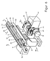
- Fig. 1 to 3 . 6 and 7 show means 1 for deforming a approximately evenly distributed on a Buckblockrücken aligned, optionally on the inside with a back insert, also called Schrenz, provided Buchdeckerücken 7 lying in the deformation lying out book cover 2, consisting essentially of two book covers and the book cover backs 7 forming middle part consists.
- the back insert is located between the covers of the book cover on the reference benefit and consists for example of cardboard or waste paper. Further relevant information can be found in DE 10'057 ⁇ 600, DE 10 ⁇ 057 ⁇ 602 or in the above-mentioned paperback book "Industrial Bookbinding".
- the Fig. 1 Figure 1 illustrates a device 1 according to the invention in an initial standby or rest position in which a deformation tool 3, designated 3, is set for the forthcoming deformation preferred for straight back formation.
- the deformation tool 3 which extends at least approximately over the length of a book height, is in the starting position at a distance below a book cover 2 for forming the Buchdecke Wegens 7 serving support level 48, which extends transversely to the conveying direction of the book block in a Ein distressmaschine (see, for example DE 1'436'086 A).
- the part of a device 1 forming deformation tool 3 consists of two facing, vertical resp.
- the tool bar 10 has approximately the length of the support strips 4, 5 and more than the width of the support strips at the largest web width. In the Fig. 2 . 3 and 6 the deformation tool 3 is in the raised position. Furthermore, the support surface 11 is provided as a management level of the tool bar 10 with sliding properties for the support strips 4, 5, so that thereon the skirting boards 8, 9 resp. let the support strips 4, 5 move easily.
- the tool bar 10 is used according to Fig.
- rotating bodies for example, about vertical axes 16, 17 drivable discs 12, 13, which are mounted in spaced along the tool carrier 10 recesses 14, 15 and at the top with respect to rotation axis 16, 17 respectively opposite drivers 18, 19; 20, 21.
- the discs 12, 13 are sunk in the tool bar 10 so that they do not touch the underside of the support strips 4, 5.
- the support strips 4, 5 have in theticianological Scheme parallel to the axis of rotation 16, 17 of the discs 12, 13 extending through openings 22, 23; 24, 25 or grooves, of the drivers 18, 19; 20, 21 are at least partially penetrated, wherein the drivers 18, 19; 20, 21 may be formed as stud bolts.
- a controller connected to a (controllable) motor can also be used.
- the on one side of the tool bar 10 above movement cam 27, 28 are by means of joints 32 or lateral guides with the oscillating on a frame 33, respectively.
- slidably mounted slide 29 connected.
- the support strips 4, 5 On the underside of the support strips 4, 5 has. This ensures that the support strips 4, 5 are adjustable transversely to the longitudinal extent of the deformation tool 3 exclusively.
- the deformation tool 3 is designed to be interchangeable, so that other support strips 4, 5 are used.
- the support strips 4, 5 can be exchanged on a deformation tool 3.
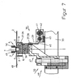
- Fig. 7 shows the arrangement between the deformation tool 3, which is also connected to the frame 33, and the sliding device 30, the slide 29 according to the execution of the Fig. 1 to 3 is connected to the deformation tool 3.
- the drive connected to the discs 12, 13, flat downwardly extending slide 29 has in the surface area a guide assembly for its displacement parallel to the longitudinal extension of the tool bar 10, on the one hand two spaced in the direction of displacement and extending in the latter slots 35, 36 and on the other a fixed to the frame 33, the slots 35, 36 associated and immersed in this sliding block 37, 38 on which the slider 29 is moved back and forth.
- a bottom-up reaching slot-like opening 39 for as Carrier trained drive cam 40 is provided which is indirectly connected to the drive motor 31.
- the slot-like opening 39 allows raising and lowering of the deformation tool 3 connected to the frame 33 Fig.
- the output shaft 41 is formed as a spindle, which intersperses a spindle nut of an adjusting 42 meshing, to which the drive cam 40 is fixed, and that on a rod 43 in the direction of the sliding movements of the slider 29 is guided.
- the 4 and 5 show the formation of the deformation tool 3 on the basis of a partial view / longitudinal section representation of the anti-slip connection between the top 11 of the tool bar 10, which rests on an intermediate element 51 designed as a heating element.
- the support strips 4, 5 may be provided on the underside, for example, with magnetic forces that generate large attraction forces on the top of the iron-containing tool bar 10.
- the support strips 4, 5 are in particular for the deformation processes at the bottom over the length of the skirting 8, 9 distributed equipped with permanent magnets 52 which are button-like and in the skirting boards 8, 9 are fixed interchangeably, for example by means of screw or adhesive.
- the magnetic surface of the permanent magnets 52 is preferably flush with the underside of the support strips 4, 5 resp. Skirts 8, 9 aligned, also on and off switchable electromagnets could be used instead of the permanent magnets.
- Known permanent magnets withstand temperatures up to 500 ° C.
- the support strips 4, 5 can be pressed over the skirting boards 8, 9 by means of screws and compression springs on the tool bar 10, wherein the support strips 4, 5 are screwed into the tool bar 10 inserted and displaceable sliding blocks.
- the in the Fig. 1 to 3 and 6 recognizable lift hook 54 is used for lifting or installation of a deformation tool 3 from the resp. in the device 1 by means of a hoist.
- a connected to the frame 33 conical positioning pin 55 is provided, which is locked under spring pressure in a designated hole on the front side of the tool bar 10.
- the intermediate element 51 is provided below the tool bar 10, which is equipped with heating elements 56 and from which the heat is transferred to the support strips 4, 5.
Landscapes
- Engineering & Computer Science (AREA)
- Manufacturing & Machinery (AREA)
- Mechanical Engineering (AREA)
- Perforating, Stamping-Out Or Severing By Means Other Than Cutting (AREA)
- Specific Conveyance Elements (AREA)
- Milling, Drilling, And Turning Of Wood (AREA)
Description
Die Erfindung betrifft eine Einrichtung zur Verformung eines auf einen Buchblockrücken etwa gleichmässig verteilt ausgerichteten, gegebenenfalls an der Innenseite eine Rückeneinlage aufweisenden Buchdeckerückens einer liegend ausgestreckte positionierten Buchdecke, bestehend aus einem auf die dem Buchblockrücken zugewandte Innenseite des Buchdeckerückens zu bewegbaren, diesen zwischen zwei seitlichen, entgegenstehenden Formfalzschienen aushebenden, einen Steg an dem Buchdeckerücken bildenden Verformungswerkzeug, das zwei benachbarte und parallel zu den Falzformschienen verlaufende Stützleisten aufweist, welche zur Einstellung der Stegbreite des Buchdeckerückens quer zur Längserstreckung der Falzformschienen gemeinsam den gegenseitigen Abstand verändernd verstellbar ausgebildet sind.The invention relates to a device for deforming a book block back approximately evenly aligned, possibly on the inside of a back insert having Buchdeckerückens a lying outstretched positioned book cover, consisting of a on the book block back facing inside of the book cover back movable, this between two lateral, opposing Formfalzschienen aushebenden, forming a web on the Buchdeckerücken forming tool having two adjacent and parallel to the Falzformschienen extending support strips which are adapted to adjust the web width of Buchdeckerückens transversely to the longitudinal extension of the Falzformschienen together the mutual distance changing adjustable.
Einrichtungen dieser Art werden bei Einhängemaschinen einer Buchfertigungslinie zur Verformung eines Buchdeckerückens eingesetzt. Auf einen vorausgehenden Teilprozess, mit dem gebundene Buchblocks insbesondere am Rücken bearbeitet werden, werden jeweils eine Buchdecke und ein Buchblock im Rückenbereich in der Einhängemaschine vereint, bevor das fertige rohe Buch abgepresst und Falze eingebrannt werden. Die Verformung eines Buchrückens erfolgt auf dem Zuführweg in die Einhängemaschine, wie dies beispielsweise in der
Aus der
Vorliegend stellt sich die Aufgabe an die Erfindung, eine robuste und kompakte Einrichtung zu schaffen, die sich zur Verformung unterschiedlich breiter Buchdeckerücken eignet und auf einfache Art einstell-, verstell- und bedienbar ist.In the present case, the object of the invention to provide a robust and compact device that is suitable for the deformation of different width Buchdecker backs and is adjustable, adjustable and easy to use.
Erfindungsgemäss wird die Aufgabe durch gelöst.According to the invention, this object is achieved by.
Diese Lösung zeichnet sich u.a. mit einem Verstellmechanismus besonders aus, bei dem die Stützleisten in der Führungsebene jeweils mit zwei entlang ihrer Längserstreckung beabstandeten und exzentrisch um eine senkrechte Achse verdrehbar angetriebenen Mitnehmern gekoppelt sind.This solution is characterized i.a. with an adjusting mechanism in particular, in which the support strips are coupled in the guide plane in each case with two spaced along its longitudinal extension and eccentrically rotatable about a vertical axis driven drivers.
Es lassen sich auch andere, zum Teil aufwändigere Verstellvorrichtungen wie Spindel- oder Schneckenantriebe etc. mit dem vorgeschlagenen System verwenden.It can also be other, sometimes more complex adjustment devices such as spindle or worm drives, etc. use with the proposed system.
Nachfolgend wird die Erfindung unter Bezugnahme auf den zitierten resp. den zitierenden Stand der Technik und die Zeichnung, auf die bezüglich aller in der Beschreibung nicht näher erwähnten Einzelheiten verwiesen wird, anhand eines Ausführungsbeispiels erläutert. In der Zeichnung zeigen:
- Fig. 1
- eine räumliche Darstellung einer erfindungsgemässen Einrichtung in der Ruhe- resp. Einstellposition,
- Fig. 2
- eine räumliche Darstellung der erfindungsgemässen Einrichtung nach
Fig. 1 in einer Verformungsposition, - Fig. 3
- eine räumliche Darstellung eines Verformungswerkzeuges mit abgenommenen Stützleisten der in den
Fig. 1 und2 gezeigten Einrichtung in einer Verformungsposition, - Fig. 4
- eine auszugsweise räumliche Darstellung des Verformungswerkzeuges in einer teilweisen Ansicht-/ Schnitt-Darstellung,
- Fig. 5
- einen Querschnitt des Verformungswerkzeuges,
- Fig. 6
- eine räumliche Darstellung einer alternativen Ausführung einer erfindungsgemässen Einrichtung bei angehobenem Verformungswerkzeug und
- Fig. 7
- einen Querschnitt der in
Fig. 2 dargestellten Einrichtung mit einem verformten Buchdeckerücken einer in die Einrichtung eingeführten Buchdecke.
- Fig. 1
- a spatial representation of an inventive device in the rest resp. setting position,
- Fig. 2
- a spatial representation of the inventive device after
Fig. 1 in a deformation position, - Fig. 3
- a spatial representation of a deformation tool with removed support strips in the
Fig. 1 and2 shown device in a deformation position, - Fig. 4
- a partial spatial representation of the deformation tool in a partial view / sectional view,
- Fig. 5
- a cross section of the deformation tool,
- Fig. 6
- a spatial representation of an alternative embodiment of an inventive device with raised deformation tool and
- Fig. 7
- a cross section of in
Fig. 2 illustrated device with a deformed Buchdeckerücken a introduced into the device book cover.
Die
Die
Damit sich die Stützleisten 4, 5 beim Verdrehen der Scheiben 12, 13 bezüglich ihrer Längsrichtung gegenseitig nicht verschieben, ist zwischen den Stützleisten 4, 5 und dem Werkzeugbalken 10 eine quer zur Längserstreckung der Stützleisten 4, 5 und des Werkzeugbalkens 10 gerichtete Führungsanordnung 34 vorgesehen, die beispielsweise eine quer zur Längserstreckung der genannten Teile verlaufende Nut 53 in dem Werkzeugbalken 10 und einen in die Nut 53 des Werkzeugbalkens 10 eingreifenden Stift 57 oder dgl. an der Unterseite der Stützleisten 4, 5 aufweist. Damit ist gewährleistet, dass die Stützleisten 4, 5 ausschliesslich quer zur Längserstreckung des Verformungswerkzeuges 3 verstellbar sind.
Das Verformungswerkzeug 3 ist austauschbar ausgebildet, sodass auch andere Stützleisten 4, 5 verwendbar sind. Ueberdies können auch die Stützleisten 4, 5 an einem Verformungswerkzeug 3 ausgetauscht werden. Diese Art Konstruktion gestattet ein rasches Austauschen der Stützleisten 4, 5.
Weiterhin lassen sich dafür geeignete Stützleisten 4, 5 sowohl mit nach innen oder nach aussen gerichteten Fussleisten 8, 9 auf dem Werkzeugbalken 10 montieren. Diese Möglichkeiten stehen für einen universellen Einsatz der Verformungseinrichtung 1 bei erheblichen Unterschieden der Stegbreite zur Verfügung.
The
Furthermore, suitable support strips 4, 5 can be mounted on the
Zur Lagerung der Abtriebswelle 41 resp. Spindel sind ein mit dem Gestell 33 verbundener Lagerschild 44 und ein Lagerbock 45 vorgesehen. Die Wahl dieser Verstellvorrichtung ist auf vorhandene Maschinenteile zurückzuführen. Es wäre auch möglich, für eine Verstellvorrichtung ein Zahnstangegetriebe zu verwenden.For storage of the
Bei einer in
Das Anheben aus der Ruhe- oder Einstellposition des Verformungswerkzeuges 3 erfolgt mittels einer in
Die
Selbstverständlich können alternativ Anziehungskräfte auf die Stützleisten 4, 5 einwirkend durch in den Werkzeugbalken 10 eingelassene Dauermagnete 52 erzeugt werden.Of course, as an alternative attraction forces can be generated on the support strips 4, 5 acting by embedded in the
Alternativ können die Stützleisten 4, 5 über die Fussleisten 8, 9 mittels Schrauben und Druckfedern auf den Werkzeugbalken 10 gepresst werden, wobei die Stützleisten 4, 5 mit in den Werkzeugbalken 10 eingelegten und versetzbaren Nutensteinen verschraubt werden.Alternatively, the support strips 4, 5 can be pressed over the
Der in den
Für eine genaue Positionierung des Verformungswerkzeuges 3 ist beispielsweise ein mit dem Gestell 33 verbundener kegeliger Positionierungsstift 55 vorgesehen, der unter Federdruck in einer dafür vorgesehenen Bohrung an der Stirnseite des Werkzeugbalkens 10 eingerastet wird.For a precise positioning of the
Bei der Verformung des Buchdeckerückens 7 werden die Stützleisten 4, 5 von unten stark erwärmt. Hierzu ist unterhalb des Werkzeugbalkens 10 das Zwischenelement 51 vorgesehen, das mit Heizstäben 56 ausgestattet ist und von dem aus die Wärme auf die Stützleisten 4, 5 übertragen wird.In the deformation of the book cover back 7, the support strips 4, 5 from below strongly heated. For this purpose, the
Claims (22)
- Device (1) for deforming a spine (7) of a book cover (2) lying in a horizontally extended position, lined up with a book block spine with approximately uniform distribution and optionally having a spine insert on the inside, [said device (1)] consisting of a deforming tool (3) movable towards the inside (side facing towards the book block spine) of the book cover spine (7) and forming a land (6) on the book cover spine (7) by lifting the latter between two lateral, opposing creasing rails (49, 50), said deforming tool (3) having two adjacent backing rails (4, 5) extending parallel with the creasing rails (49, 50), characterized in that the backing rails (4, 5) are designed to be movable simultaneously, altering the distance between them, at right angles to the longitudinal extent of the creasing rails (49, 50), so as to set the land width of the book cover spine (7), and in that the backing rails (4, 5) are supported on, and non-positively or positively attached to, a beam (10) of the deforming tool (3) with a guide plane on its upper side, each backing rail (4, 5) being respectively coupled to two driven dogs (18, 19; 20, 21).
- Device according to Claim 1, characterized in that each backing rail (4, 5), resting in a guide plane, is respectively coupled to two dogs (18, 19; 20, 21) which are spaced apart along the longitudinal extent of the backing rail and are each rotatably driven eccentrically about a vertical axis (16, 17).
- Device according to Claim 2, characterized in that two dogs (18, 19; 20, 21) mounted on one rotatable disc (12, 13) are respectively assigned to each axis (16, 17).
- Device according to Claim 3, characterized in that the dogs (18, 19; 20, 21) are mounted on the rotatable disc (12, 13) on opposite sides of the axis (16, 17).
- Device according to Claim 3 or Claim 4, characterized in that the discs (12, 13) are mounted in a beam (10) of the deforming tool (3).
- Device according to any one of Claims 1 to 5, characterized in that the guide plane is formed by a bearing surface (11) on the tool beam (10).
- Device according to any one of Claims 1 to 6, characterized in that the backing rails (4, 5) are non-positively or positively attached to the bearing surface (11) of the tool beam (10).
- Device according to Claim 7, characterized in that the backing rails (4, 5) are attached to the tool beam (10) by magnetic forces.
- Device according to Claim 8, characterized in that the backing rails (4, 5) have permanent magnets (52) on their underside, distributed over their length, each of whose surfaces acting magnetically on the tool beam (10) is aligned flush with the underside of the backing rails (4, 5), or [of] the baseplates (8, 9) of the backing rails (4, 5).
- Device according to any one of Claims 7 to 9, characterized in that the tool beam (10) has an at least partly magnetic surface acting on the ferrous-metal backing elements (4, 5).
- Device according to any one of Claims 3 to 10, characterized in that the rotatable discs (12, 13) have a driving connection to a slide mechanism (30).
- Device according to any one of Claims 3 to 11, characterized in that the discs (12, 13) are each rotatable through an acute angle at the axis (16, 17).
- Device according to any one of Claims 3 to 12, characterized in that the discs (12, 13) each have an actuating cam (27, 28) connected to the slider (29) at their periphery.
- Device according to any one of Claims 3 to 13, characterized in that the rotatable discs (12, 13) can be separated from the slide mechanism (30) by raising the tool beam (10).
- Device according to any one of Claims 11 to 14, characterized in that the slide mechanism (30) is connected to a spindle drive.
- Device according to any one of Claims 1 to 15, characterized in that the backing rails (4, 5) are adjustable in a guide arrangement (34) extending at right angles to their longitudinal extent.
- Device according to Claim 16, characterized in that the guide arrangement (34) has a keyway (53) in the tool beam (10), extending at right angles to the longitudinal extent of the backing rails (4, 5), to seat a guide key (55) of the backing rails (4, 5).
- Device according to any one of Claims 11 to 17, characterized in that the adjusting motions of the guide mechanism (30) are orientated parallel with the longitudinal extent of the backing rails (4, 5).
- Device according to any one of Claims 11 to 18, characterized in that a slider (29) of the slide mechanism (30) is guided displaceably in a slide arrangement (35, 37; 36, 38) mounted on a frame (33).
- Device according to Claim 19, characterized in that the downwards-jutting slider (29) has a vertically-extending opening (39) into which the drive cam (40) of a traversing member (42) connected to the spindle drive reaches.
- Device according to Claim 20, characterized in that the slider (29) is mounted on the traversing member (42).
- Device according to any one of Claims 5 to 21, characterized in that the tool beam (10) is arranged on a heating element configured as an intermediate element (51).
Priority Applications (2)
| Application Number | Priority Date | Filing Date | Title |
|---|---|---|---|
| EP09405201.6A EP2325020B1 (en) | 2009-11-23 | 2009-11-23 | Device for deforming a book cover spine of a book cover aligned on a book block spine |
| US12/952,942 US8439621B2 (en) | 2009-11-23 | 2010-11-23 | Device for shaping a back of a book cover that is aligned with a book block spine |
Applications Claiming Priority (1)
| Application Number | Priority Date | Filing Date | Title |
|---|---|---|---|
| EP09405201.6A EP2325020B1 (en) | 2009-11-23 | 2009-11-23 | Device for deforming a book cover spine of a book cover aligned on a book block spine |
Publications (2)
| Publication Number | Publication Date |
|---|---|
| EP2325020A1 EP2325020A1 (en) | 2011-05-25 |
| EP2325020B1 true EP2325020B1 (en) | 2013-06-19 |
Family
ID=41728476
Family Applications (1)
| Application Number | Title | Priority Date | Filing Date |
|---|---|---|---|
| EP09405201.6A Active EP2325020B1 (en) | 2009-11-23 | 2009-11-23 | Device for deforming a book cover spine of a book cover aligned on a book block spine |
Country Status (2)
| Country | Link |
|---|---|
| US (1) | US8439621B2 (en) |
| EP (1) | EP2325020B1 (en) |
Families Citing this family (5)
| Publication number | Priority date | Publication date | Assignee | Title |
|---|---|---|---|---|
| DE102014004614A1 (en) | 2014-03-29 | 2015-10-01 | Kolbus Gmbh & Co. Kg | Device for forming book covers |
| JP2017136831A (en) * | 2016-02-01 | 2017-08-10 | ミュラー・マルティニ・ホルディング・アクチエンゲゼルシヤフト | Device for preforming and rounding book block |
| EP3235654B1 (en) | 2016-04-21 | 2019-01-30 | Müller Martini Holding AG | Shaping tool and device for the forming of book covers |
| EP3235653B1 (en) | 2016-04-21 | 2018-10-03 | Müller Martini Holding AG | Pre-heat station for a shaping tool for reforming book covers |
| EP3235652B1 (en) | 2016-04-21 | 2018-09-26 | Müller Martini Holding AG | Device for forming of book covers |
Citations (1)
| Publication number | Priority date | Publication date | Assignee | Title |
|---|---|---|---|---|
| DE102006033117A1 (en) * | 2006-07-18 | 2008-01-24 | Kolbus Gmbh & Co. Kg | Method and device for creating a hinge-like, bendable zone in a sheet of paper, cardboard, cardboard or foil |
Family Cites Families (14)
| Publication number | Priority date | Publication date | Assignee | Title |
|---|---|---|---|---|
| US2640208A (en) * | 1948-11-13 | 1953-06-02 | Florez Company Inc De | Method and apparatus for building in the cases of books |
| US3201810A (en) | 1962-10-04 | 1965-08-24 | Smyth Mfg Co | Heating means for casing-in machine |
| US3398038A (en) * | 1965-10-24 | 1968-08-20 | Crawford Jay | Book cover turning-in machine |
| GB1501443A (en) * | 1975-01-29 | 1978-02-15 | Korsgaard J | Method and apparatus for binding a book |
| US5203590A (en) * | 1990-10-31 | 1993-04-20 | Hertzberg-New Method, Inc. | Bound book with reinforced fabric strips |
| DE19729529B4 (en) * | 1996-09-13 | 2010-04-08 | Kolbus Gmbh & Co. Kg | Method and apparatus for making a book |
| US5980182A (en) * | 1998-06-23 | 1999-11-09 | Duplo Usa Corporation | Case-in device of adhesive bookbinder |
| DE19853254A1 (en) * | 1998-11-18 | 2000-05-25 | Kolbus Gmbh & Co Kg | Mold device for book covers has molding bar acting with pressure pad with deformable active surface to round cover back |
| US6364590B1 (en) * | 2000-08-01 | 2002-04-02 | Hewlett-Packard Company | Book cover preparation system |
| DE10057600B4 (en) | 2000-11-21 | 2008-10-09 | Kolbus Gmbh & Co. Kg | Device for feeding back inserts for the manufacture of book covers |
| DE10057602C5 (en) | 2000-11-21 | 2014-09-11 | Kolbus Gmbh & Co. Kg | Device for making book covers |
| JP4760512B2 (en) * | 2005-08-11 | 2011-08-31 | コニカミノルタビジネステクノロジーズ株式会社 | Bookbinding equipment |
| DE502005010765D1 (en) * | 2005-10-25 | 2011-02-10 | Mueller Martini Holding Ag | Device for rubbing a book cover on the glued outer surfaces of book blocks with separate drive |
| JP4868933B2 (en) * | 2006-05-02 | 2012-02-01 | ニスカ株式会社 | Bookbinding apparatus and image forming apparatus having the same |
-
2009
- 2009-11-23 EP EP09405201.6A patent/EP2325020B1/en active Active
-
2010
- 2010-11-23 US US12/952,942 patent/US8439621B2/en active Active
Patent Citations (1)
| Publication number | Priority date | Publication date | Assignee | Title |
|---|---|---|---|---|
| DE102006033117A1 (en) * | 2006-07-18 | 2008-01-24 | Kolbus Gmbh & Co. Kg | Method and device for creating a hinge-like, bendable zone in a sheet of paper, cardboard, cardboard or foil |
Also Published As
| Publication number | Publication date |
|---|---|
| US8439621B2 (en) | 2013-05-14 |
| US20110123298A1 (en) | 2011-05-26 |
| EP2325020A1 (en) | 2011-05-25 |
Similar Documents
| Publication | Publication Date | Title |
|---|---|---|
| EP2325020B1 (en) | Device for deforming a book cover spine of a book cover aligned on a book block spine | |
| EP1780038B2 (en) | Device for grinding a book cover onto the glued back of a book block having a separate drive | |
| EP2139634B1 (en) | Cutting device | |
| EP2392438B1 (en) | Processing device | |
| AT516708B1 (en) | Support table for bending machine | |
| EP2923852B1 (en) | Device for forming of book covers | |
| EP2949437B1 (en) | Scraper blade device | |
| EP3112083B1 (en) | Portal assembly of a machine tool and machine tool with such a portal assembly | |
| EP2191948B1 (en) | Device for working panel edges | |
| EP3406456B1 (en) | Adhesive binder | |
| EP3235653B1 (en) | Pre-heat station for a shaping tool for reforming book covers | |
| EP3235652B1 (en) | Device for forming of book covers | |
| EP3235654B1 (en) | Shaping tool and device for the forming of book covers | |
| EP2347912B1 (en) | Device for moulding the back of book block | |
| EP1593467A1 (en) | A device to handle a staple of sheets | |
| EP2650138B1 (en) | Book moulding and pressing machine | |
| EP2277710B1 (en) | Device for reforming a book cover spine of a book cover aligned on a book block spine | |
| WO2011054488A1 (en) | Clamping unit for an injection molding machine | |
| EP3199369B1 (en) | Method of preforming and rounding a book block | |
| AT516434B1 (en) | Finishing unit with position adjustable copying device | |
| EP1638711B1 (en) | Embossing machine and method for embossing workpieces | |
| EP2650139B1 (en) | Book moulding and pressing machine | |
| EP2711192B1 (en) | Device for laying a cover | |
| DE19514395C2 (en) | Method for handling a stack of sheets and device for carrying out this method | |
| EP3037245A1 (en) | Method and device for edgefolding |
Legal Events
| Date | Code | Title | Description |
|---|---|---|---|
| PUAI | Public reference made under article 153(3) epc to a published international application that has entered the european phase |
Free format text: ORIGINAL CODE: 0009012 |
|
| AK | Designated contracting states |
Kind code of ref document: A1 Designated state(s): AT BE BG CH CY CZ DE DK EE ES FI FR GB GR HR HU IE IS IT LI LT LU LV MC MK MT NL NO PL PT RO SE SI SK SM TR |
|
| AX | Request for extension of the european patent |
Extension state: AL BA RS |
|
| 17P | Request for examination filed |
Effective date: 20110830 |
|
| 17Q | First examination report despatched |
Effective date: 20110919 |
|
| GRAP | Despatch of communication of intention to grant a patent |
Free format text: ORIGINAL CODE: EPIDOSNIGR1 |
|
| GRAP | Despatch of communication of intention to grant a patent |
Free format text: ORIGINAL CODE: EPIDOSNIGR1 |
|
| INTG | Intention to grant announced |
Effective date: 20130402 |
|
| GRAS | Grant fee paid |
Free format text: ORIGINAL CODE: EPIDOSNIGR3 |
|
| GRAA | (expected) grant |
Free format text: ORIGINAL CODE: 0009210 |
|
| AK | Designated contracting states |
Kind code of ref document: B1 Designated state(s): AT BE BG CH CY CZ DE DK EE ES FI FR GB GR HR HU IE IS IT LI LT LU LV MC MK MT NL NO PL PT RO SE SI SK SM TR |
|
| REG | Reference to a national code |
Ref country code: GB Ref legal event code: FG4D Free format text: NOT ENGLISH |
|
| REG | Reference to a national code |
Ref country code: CH Ref legal event code: EP |
|
| REG | Reference to a national code |
Ref country code: AT Ref legal event code: REF Ref document number: 617423 Country of ref document: AT Kind code of ref document: T Effective date: 20130715 |
|
| REG | Reference to a national code |
Ref country code: IE Ref legal event code: FG4D Free format text: LANGUAGE OF EP DOCUMENT: GERMAN |
|
| REG | Reference to a national code |
Ref country code: DE Ref legal event code: R096 Ref document number: 502009007366 Country of ref document: DE Effective date: 20130814 |
|
| PG25 | Lapsed in a contracting state [announced via postgrant information from national office to epo] |
Ref country code: SE Free format text: LAPSE BECAUSE OF FAILURE TO SUBMIT A TRANSLATION OF THE DESCRIPTION OR TO PAY THE FEE WITHIN THE PRESCRIBED TIME-LIMIT Effective date: 20130619 Ref country code: SI Free format text: LAPSE BECAUSE OF FAILURE TO SUBMIT A TRANSLATION OF THE DESCRIPTION OR TO PAY THE FEE WITHIN THE PRESCRIBED TIME-LIMIT Effective date: 20130619 Ref country code: FI Free format text: LAPSE BECAUSE OF FAILURE TO SUBMIT A TRANSLATION OF THE DESCRIPTION OR TO PAY THE FEE WITHIN THE PRESCRIBED TIME-LIMIT Effective date: 20130619 Ref country code: ES Free format text: LAPSE BECAUSE OF FAILURE TO SUBMIT A TRANSLATION OF THE DESCRIPTION OR TO PAY THE FEE WITHIN THE PRESCRIBED TIME-LIMIT Effective date: 20130930 Ref country code: LT Free format text: LAPSE BECAUSE OF FAILURE TO SUBMIT A TRANSLATION OF THE DESCRIPTION OR TO PAY THE FEE WITHIN THE PRESCRIBED TIME-LIMIT Effective date: 20130619 Ref country code: NO Free format text: LAPSE BECAUSE OF FAILURE TO SUBMIT A TRANSLATION OF THE DESCRIPTION OR TO PAY THE FEE WITHIN THE PRESCRIBED TIME-LIMIT Effective date: 20130919 Ref country code: GR Free format text: LAPSE BECAUSE OF FAILURE TO SUBMIT A TRANSLATION OF THE DESCRIPTION OR TO PAY THE FEE WITHIN THE PRESCRIBED TIME-LIMIT Effective date: 20130920 |
|
| REG | Reference to a national code |
Ref country code: LT Ref legal event code: MG4D |
|
| PG25 | Lapsed in a contracting state [announced via postgrant information from national office to epo] |
Ref country code: HR Free format text: LAPSE BECAUSE OF FAILURE TO SUBMIT A TRANSLATION OF THE DESCRIPTION OR TO PAY THE FEE WITHIN THE PRESCRIBED TIME-LIMIT Effective date: 20130619 Ref country code: BG Free format text: LAPSE BECAUSE OF FAILURE TO SUBMIT A TRANSLATION OF THE DESCRIPTION OR TO PAY THE FEE WITHIN THE PRESCRIBED TIME-LIMIT Effective date: 20130919 |
|
| REG | Reference to a national code |
Ref country code: NL Ref legal event code: VDEP Effective date: 20130619 |
|
| PG25 | Lapsed in a contracting state [announced via postgrant information from national office to epo] |
Ref country code: LV Free format text: LAPSE BECAUSE OF FAILURE TO SUBMIT A TRANSLATION OF THE DESCRIPTION OR TO PAY THE FEE WITHIN THE PRESCRIBED TIME-LIMIT Effective date: 20130619 |
|
| PG25 | Lapsed in a contracting state [announced via postgrant information from national office to epo] |
Ref country code: PT Free format text: LAPSE BECAUSE OF FAILURE TO SUBMIT A TRANSLATION OF THE DESCRIPTION OR TO PAY THE FEE WITHIN THE PRESCRIBED TIME-LIMIT Effective date: 20131021 Ref country code: CY Free format text: LAPSE BECAUSE OF FAILURE TO SUBMIT A TRANSLATION OF THE DESCRIPTION OR TO PAY THE FEE WITHIN THE PRESCRIBED TIME-LIMIT Effective date: 20130717 Ref country code: EE Free format text: LAPSE BECAUSE OF FAILURE TO SUBMIT A TRANSLATION OF THE DESCRIPTION OR TO PAY THE FEE WITHIN THE PRESCRIBED TIME-LIMIT Effective date: 20130619 Ref country code: CZ Free format text: LAPSE BECAUSE OF FAILURE TO SUBMIT A TRANSLATION OF THE DESCRIPTION OR TO PAY THE FEE WITHIN THE PRESCRIBED TIME-LIMIT Effective date: 20130619 Ref country code: SK Free format text: LAPSE BECAUSE OF FAILURE TO SUBMIT A TRANSLATION OF THE DESCRIPTION OR TO PAY THE FEE WITHIN THE PRESCRIBED TIME-LIMIT Effective date: 20130619 Ref country code: IS Free format text: LAPSE BECAUSE OF FAILURE TO SUBMIT A TRANSLATION OF THE DESCRIPTION OR TO PAY THE FEE WITHIN THE PRESCRIBED TIME-LIMIT Effective date: 20131019 |
|
| PG25 | Lapsed in a contracting state [announced via postgrant information from national office to epo] |
Ref country code: NL Free format text: LAPSE BECAUSE OF FAILURE TO SUBMIT A TRANSLATION OF THE DESCRIPTION OR TO PAY THE FEE WITHIN THE PRESCRIBED TIME-LIMIT Effective date: 20130619 Ref country code: PL Free format text: LAPSE BECAUSE OF FAILURE TO SUBMIT A TRANSLATION OF THE DESCRIPTION OR TO PAY THE FEE WITHIN THE PRESCRIBED TIME-LIMIT Effective date: 20130619 Ref country code: RO Free format text: LAPSE BECAUSE OF FAILURE TO SUBMIT A TRANSLATION OF THE DESCRIPTION OR TO PAY THE FEE WITHIN THE PRESCRIBED TIME-LIMIT Effective date: 20130619 |
|
| PG25 | Lapsed in a contracting state [announced via postgrant information from national office to epo] |
Ref country code: CY Free format text: LAPSE BECAUSE OF FAILURE TO SUBMIT A TRANSLATION OF THE DESCRIPTION OR TO PAY THE FEE WITHIN THE PRESCRIBED TIME-LIMIT Effective date: 20130619 |
|
| PLBE | No opposition filed within time limit |
Free format text: ORIGINAL CODE: 0009261 |
|
| STAA | Information on the status of an ep patent application or granted ep patent |
Free format text: STATUS: NO OPPOSITION FILED WITHIN TIME LIMIT |
|
| PG25 | Lapsed in a contracting state [announced via postgrant information from national office to epo] |
Ref country code: DK Free format text: LAPSE BECAUSE OF FAILURE TO SUBMIT A TRANSLATION OF THE DESCRIPTION OR TO PAY THE FEE WITHIN THE PRESCRIBED TIME-LIMIT Effective date: 20130619 |
|
| 26N | No opposition filed |
Effective date: 20140320 |
|
| BERE | Be: lapsed |
Owner name: MULLER MARTINI HOLDING A.G. Effective date: 20131130 |
|
| REG | Reference to a national code |
Ref country code: DE Ref legal event code: R097 Ref document number: 502009007366 Country of ref document: DE Effective date: 20140320 |
|
| GBPC | Gb: european patent ceased through non-payment of renewal fee |
Effective date: 20131123 |
|
| PG25 | Lapsed in a contracting state [announced via postgrant information from national office to epo] |
Ref country code: MC Free format text: LAPSE BECAUSE OF FAILURE TO SUBMIT A TRANSLATION OF THE DESCRIPTION OR TO PAY THE FEE WITHIN THE PRESCRIBED TIME-LIMIT Effective date: 20130619 |
|
| REG | Reference to a national code |
Ref country code: FR Ref legal event code: ST Effective date: 20140731 |
|
| REG | Reference to a national code |
Ref country code: IE Ref legal event code: MM4A |
|
| PG25 | Lapsed in a contracting state [announced via postgrant information from national office to epo] |
Ref country code: BE Free format text: LAPSE BECAUSE OF NON-PAYMENT OF DUE FEES Effective date: 20131130 |
|
| PG25 | Lapsed in a contracting state [announced via postgrant information from national office to epo] |
Ref country code: IE Free format text: LAPSE BECAUSE OF NON-PAYMENT OF DUE FEES Effective date: 20131123 |
|
| PG25 | Lapsed in a contracting state [announced via postgrant information from national office to epo] |
Ref country code: GB Free format text: LAPSE BECAUSE OF NON-PAYMENT OF DUE FEES Effective date: 20131123 Ref country code: FR Free format text: LAPSE BECAUSE OF NON-PAYMENT OF DUE FEES Effective date: 20131202 |
|
| PG25 | Lapsed in a contracting state [announced via postgrant information from national office to epo] |
Ref country code: SM Free format text: LAPSE BECAUSE OF FAILURE TO SUBMIT A TRANSLATION OF THE DESCRIPTION OR TO PAY THE FEE WITHIN THE PRESCRIBED TIME-LIMIT Effective date: 20130619 |
|
| PG25 | Lapsed in a contracting state [announced via postgrant information from national office to epo] |
Ref country code: TR Free format text: LAPSE BECAUSE OF FAILURE TO SUBMIT A TRANSLATION OF THE DESCRIPTION OR TO PAY THE FEE WITHIN THE PRESCRIBED TIME-LIMIT Effective date: 20130619 |
|
| PG25 | Lapsed in a contracting state [announced via postgrant information from national office to epo] |
Ref country code: MK Free format text: LAPSE BECAUSE OF FAILURE TO SUBMIT A TRANSLATION OF THE DESCRIPTION OR TO PAY THE FEE WITHIN THE PRESCRIBED TIME-LIMIT Effective date: 20130619 Ref country code: HU Free format text: LAPSE BECAUSE OF FAILURE TO SUBMIT A TRANSLATION OF THE DESCRIPTION OR TO PAY THE FEE WITHIN THE PRESCRIBED TIME-LIMIT; INVALID AB INITIO Effective date: 20091123 Ref country code: LU Free format text: LAPSE BECAUSE OF NON-PAYMENT OF DUE FEES Effective date: 20131123 |
|
| PG25 | Lapsed in a contracting state [announced via postgrant information from national office to epo] |
Ref country code: MT Free format text: LAPSE BECAUSE OF FAILURE TO SUBMIT A TRANSLATION OF THE DESCRIPTION OR TO PAY THE FEE WITHIN THE PRESCRIBED TIME-LIMIT Effective date: 20130619 |
|
| REG | Reference to a national code |
Ref country code: AT Ref legal event code: MM01 Ref document number: 617423 Country of ref document: AT Kind code of ref document: T Effective date: 20141123 |
|
| PG25 | Lapsed in a contracting state [announced via postgrant information from national office to epo] |
Ref country code: AT Free format text: LAPSE BECAUSE OF NON-PAYMENT OF DUE FEES Effective date: 20141123 |
|
| PGFP | Annual fee paid to national office [announced via postgrant information from national office to epo] |
Ref country code: CH Payment date: 20200221 Year of fee payment: 11 |
|
| REG | Reference to a national code |
Ref country code: CH Ref legal event code: PL |
|
| PG25 | Lapsed in a contracting state [announced via postgrant information from national office to epo] |
Ref country code: LI Free format text: LAPSE BECAUSE OF NON-PAYMENT OF DUE FEES Effective date: 20201130 Ref country code: CH Free format text: LAPSE BECAUSE OF NON-PAYMENT OF DUE FEES Effective date: 20201130 |
|
| PGFP | Annual fee paid to national office [announced via postgrant information from national office to epo] |
Ref country code: IT Payment date: 20231129 Year of fee payment: 15 Ref country code: DE Payment date: 20231121 Year of fee payment: 15 |