EP2324730B1 - Lippenstift mit Inkliner - Google Patents
Lippenstift mit Inkliner Download PDFInfo
- Publication number
- EP2324730B1 EP2324730B1 EP09175277A EP09175277A EP2324730B1 EP 2324730 B1 EP2324730 B1 EP 2324730B1 EP 09175277 A EP09175277 A EP 09175277A EP 09175277 A EP09175277 A EP 09175277A EP 2324730 B1 EP2324730 B1 EP 2324730B1
- Authority
- EP
- European Patent Office
- Prior art keywords
- applicator
- housing
- lid
- foot
- lipstick
- Prior art date
- Legal status (The legal status is an assumption and is not a legal conclusion. Google has not performed a legal analysis and makes no representation as to the accuracy of the status listed.)
- Not-in-force
Links
- 239000002537 cosmetic Substances 0.000 claims abstract description 53
- 230000007246 mechanism Effects 0.000 claims abstract description 23
- 239000007788 liquid Substances 0.000 claims description 23
- 239000000463 material Substances 0.000 description 3
- 239000002184 metal Substances 0.000 description 3
- 239000003086 colorant Substances 0.000 description 2
- 235000010678 Paulownia tomentosa Nutrition 0.000 description 1
- 240000002834 Paulownia tomentosa Species 0.000 description 1
- 230000000740 bleeding effect Effects 0.000 description 1
- 239000003795 chemical substances by application Substances 0.000 description 1
- 230000018044 dehydration Effects 0.000 description 1
- 238000006297 dehydration reaction Methods 0.000 description 1
- 230000006866 deterioration Effects 0.000 description 1
- 238000001035 drying Methods 0.000 description 1
- 230000000694 effects Effects 0.000 description 1
- 230000001771 impaired effect Effects 0.000 description 1
- 238000003780 insertion Methods 0.000 description 1
- 230000037431 insertion Effects 0.000 description 1
- 230000003020 moisturizing effect Effects 0.000 description 1
- 238000000926 separation method Methods 0.000 description 1
- 239000007787 solid Substances 0.000 description 1
- 239000000126 substance Substances 0.000 description 1
Images

Classifications
-
- A—HUMAN NECESSITIES
- A45—HAND OR TRAVELLING ARTICLES
- A45D—HAIRDRESSING OR SHAVING EQUIPMENT; EQUIPMENT FOR COSMETICS OR COSMETIC TREATMENTS, e.g. FOR MANICURING OR PEDICURING
- A45D40/00—Casings or accessories specially adapted for storing or handling solid or pasty toiletry or cosmetic substances, e.g. shaving soaps or lipsticks
- A45D40/24—Casings for two or more cosmetics
-
- A—HUMAN NECESSITIES
- A45—HAND OR TRAVELLING ARTICLES
- A45D—HAIRDRESSING OR SHAVING EQUIPMENT; EQUIPMENT FOR COSMETICS OR COSMETIC TREATMENTS, e.g. FOR MANICURING OR PEDICURING
- A45D40/00—Casings or accessories specially adapted for storing or handling solid or pasty toiletry or cosmetic substances, e.g. shaving soaps or lipsticks
- A45D40/02—Casings wherein movement of the lipstick or like solid is a sliding movement
- A45D40/04—Casings wherein movement of the lipstick or like solid is a sliding movement effected by a screw
-
- A—HUMAN NECESSITIES
- A45—HAND OR TRAVELLING ARTICLES
- A45D—HAIRDRESSING OR SHAVING EQUIPMENT; EQUIPMENT FOR COSMETICS OR COSMETIC TREATMENTS, e.g. FOR MANICURING OR PEDICURING
- A45D40/00—Casings or accessories specially adapted for storing or handling solid or pasty toiletry or cosmetic substances, e.g. shaving soaps or lipsticks
- A45D40/20—Pencil-like cosmetics; Simple holders for handling stick-shaped cosmetics or shaving soap while in use
Definitions
- the present invention relates to a novel device including two applicators for applying cosmetic components.
- Applicators are, for example, brush, pen, tube, nozzle or rod-shaped tools for applying cosmetic components.
- An example of commonly used and known applicators are lipsticks.
- Lipsticks basically contain at least one cosmetic component.
- the lipstick lead is formed from at least one cosmetic component. By guiding the lipstick lead along a lip, this component spreads to the lip. Accordingly, in the case of lipstick, the applicator consists of the lipstick lead and therefore of the cosmetic component itself.
- a lip contour pencil can either consist of a solid cosmetic component, the so-called lip contour pencil lead, or can be applied in liquid form via a felt-tip-like applicator. Lips contour pins are mostly used to prevent bleeding or smearing of the applied lipstick.
- Another example of an applicator is a so-called lip gloss, which usually consists of a liquefied, often enriched with care agents and moisturizing substances lip color and is applied by means of a brush-like applicator.
- lip gloss which usually consists of a liquefied, often enriched with care agents and moisturizing substances lip color and is applied by means of a brush-like applicator.
- a user usually uses several different applicators for applying various cosmetic components. For example, a user first uses a lipstick and then traces the lip contour with a lip contour pin. Also, for example, a user may use a transparent lip gloss to give the applied lipstick more shine, the lip gloss being dabbed onto the already applied lipstick by means of a brush-like applicator and dispensed by a subsequent brief squeezing of the lips.
- a multiple applicator device that facilitates the user's manipulation by uniting the functionality of multiple objects in an article is characterized US 2002/0071707 A1 known.
- US 2002/0071707 A1 shows a housing open at two ends with Aufsteckhülsen.
- Applicators for cosmetic components can be attached to these sleeves. These may be, for example, lipsticks with different colors or a lipstick and a lip gloss.
- the applicators themselves are thereby inserted into the sleeves and closed by lids.
- the covers protect the applicators when they are not in use.
- the lid of the applicator serves as a container for the liquid cosmetic component. In this case, the applicator thus immersed in the liquid component.
- the brush-like applicator is inserted into the slip-on sleeve, the lid is filled with the liquid lip gloss, and then the applicator is closed with the lid.
- the device has the disadvantage that, due to the described use of the housing, the entire device is larger than the two applicators together. This means that while the user only has to carry one item, it is larger than the two items. Especially in the situation in which the user carries only a small handbag with him or the object finds room only in the pocket, the larger external dimensions of the object are unfavorable. Furthermore, when handling the device, the user must always make sure that the device is opened in the correct position to prevent liquid from escaping from the lid, for example, during opening.
- a device according to the preamble of claim 1 is known from US Pat. No. 2,964,045 known.
- the device according to the invention has a housing, a first applicator for applying at least one cosmetic component and a second applicator for applying at least one cosmetic component.
- the first applicator is at least partially disposed in the housing.
- This first applicator consists of a first cosmetic component for application, that is to say the user can apply the first component, for example, to a lip. In this case, parts of the cosmetic component are removed on the surface of the applicator coming into contact with the lip and transferred to the lip.
- the first applicator may be, for example, a lipstick that consists of a lipstick lead.
- the lipstick lead itself is the first applicator in this case.
- a lid is arranged in the first applicator and in this lid, in turn, the second applicator is removably arranged.
- the lid is a wall that delimits the area of the first applicator from the area of the second applicator. Through the lid a space closed at least on one side is formed, in which the second applicator can be arranged.
- the lid thereby protects the second applicator not only from drying out, but also represents a delimitation of the applicator from the environment. This is particularly necessary because the lid of the second applicator according to the invention, at least partially, is arranged in the first applicator.
- the lid extends through a substantial part of the first applicator.
- the lid forms a space within the first applicator which is separate from the first applicator and into which the second applicator is insertable and in which the second applicator is stowable.
- the lid covers not only the second applicator but also parts arranged thereon.
- the stowed in the lid second applicator and any other parts are removed according to the invention for use of the lid.
- the lid itself can remain in the first applicator. If the second applicator is not in use, it can be stowed back in the lid within the first applicator. With the help of the lid, the second applicator can thus be arranged in the first applicator without the two applicators coming into direct contact.
- the device according to the invention provides the user for the first time with a device in which two applicators for applying cosmetic components can be arranged very compactly and the device nevertheless ensures the user easy handling of the two applicators.
- the compact design of the device is made possible in that the second applicator is at least partially located in the first applicator and is separated therefrom by the lid. Due to this clear separation, the second applicator does not come in direct contact with the first applicator and can not be contaminated.
- the compact arrangement of the applicators into one another has the advantage that the user only has to carry a very compact object with him but is nevertheless able to do so Apply different cosmetic components.
- the size of the device with the two applicators arranged one inside the other is only marginally larger than a single applicator taken on its own.
- the size of the device according to the invention in which both applicators are arranged one inside the other is not much larger than the lipstick taken alone.
- the second applicator is removable from the device on one side. This is the side opposite the face for applying the cosmetic component of the first applicator. So opposite to a surface on which parts of the first applicator are removed and applied, for example, to a lip. After use, the second applicator can then be stowed in the lid again.
- the handling of the device for the user is substantially facilitated by the fact that the device for using the two applicators does not have to be rotated.
- the upper side of the device can be used to apply a lipstick by means of the first applicator and the second applicator can be removed / inserted on the underside of the lipstick. This eliminates a rotation of the device, as is necessary for example in known Mehrfachapplikatorvorraumen.
- the device preferably also has means for moving the first applicator, at least partially, out of the housing and into the housing, independently of the second applicator.
- the means is preferably realized by a rotating mechanism.
- the rotary mechanism has a rotary element, wherein the rotary element is rotatable relative to the housing. The rotary element is thus not firmly connected to the housing.
- the rotary mechanism preferably has a thread. This thread can be arranged either on the inside of the housing or on the outside the lid, that is on the side of the lid, which is in direct communication with the first applicator. With the aid of this rotation mechanism, the movement of the first applicator can be realized in a simple manner without space-consuming and complicated components.
- the first applicator is arranged in a basket.
- This basket is moved in a preferred embodiment by means of the thread and the rotary member up and down to move the first applicator as desired from the housing or into the housing inside.
- the basket preferably has an opening in the middle, through which the lid or the second applicator can be guided. The opening allows the basket to be guided along the second applicator.
- a foot is disposed on the second applicator.
- the foot can be made of metal or plastic, for example.
- the foot preferably has the same or a similar cross-section as the housing of the device according to the invention, so that the foot of the second applicator, when stowed in the lid, forms a base of the device according to the invention on which, for example, the device can stand.
- the foot may be configured to include a receptacle for various applicators and other parts disposed thereon. Through this recording, it is then possible for the user to change the applicator.
- the foot is preferably rotatably connected to the rotary member of the rotating mechanism, so that the rotation mechanism can be made very compact, but the user is still a comfortable handling possible. If the foot is non-rotatably connectable to the rotary member, the user no longer needs to engage the rotary member itself to move the first applicator out of or into the housing. Instead, the user can attack the foot. In this embodiment, the foot is rotated together with the rotary member relative to the housing to the first Applicator in the housing into or out of the housing to move out.
- the rotationally fixed connection can be realized for example by interlocking teeth. But other known to the expert rotatable connections are conceivable. It is important to ensure that the complexity of the connection does not affect the handling.
- the foot of the second applicator must be easy to connect to the rotating element and can also be quickly released again to ensure easy use of the second applicator.
- the fact that the foot can be connected to the rotary element, the rotary element itself can be made very compact, so that the size of the device can be kept very small overall.
- the housing of the device can be connected in a rotationally fixed manner to the foot of the second applicator.
- a rotation of the foot also leads to a relative movement between the rotary element and the housing.
- This configuration allows the user to attack the rotating element and the foot without having to touch the housing.
- This has the advantage, for example, in metal housings or high-gloss housings that they are not contaminated.
- the fact that the housing does not have to be touched directly in order to move the first applicator out of or into the housing also has the advantage that the housing can be made very thin-walled, since there is no danger of it being pressed too hard is compressed and thereby either the applicator and / or the rotation mechanism is impaired.
- the foot of the second applicator should be easy to connect to the housing and can also be solved quickly to ensure easy use of the second applicator.
- the foot and the rotary element or the housing may also be non-rotatably connected to each other.
- the user is further clarified, for example, the bipartite nature of the device.
- the second applicator consists of a second cosmetic component for application, for example from a lip contour pencil lead.
- the Lippenkonturxmine is enclosed by the lid, so that they can be placed in the first applicator without directly in contact with the first applicator.
- the lid remains in the first applicator, where it forms the space in which the Lippenkonturxmine can be stowed after use again. This has the further advantage that the Lippenkonturxmine is protected from dehydration.
- the second applicator may also be a stylus for applying a liquid cosmetic component.
- the liquid cosmetic component may be located in a container which is arranged on the second applicator.
- the container may for example also be partially arranged in the lid.
- the foot of the second applicator may include the container for the liquid cosmetic component.
- the foot and the container may also be designed in one piece.
- the foot and the container may cooperate such that when the foot is compressed, the pressure in the container may increase and the liquid cosmetic component may leak from the applicator.
- a type of check valve may be arranged between the applicator and the container, which only allows the liquid cosmetic component to pass to the applicator when the pressure in the container is adequate.
- the second applicator can also be a so-called automatic pen, which can be rotated back and forth.
- an automatic pin of the foot and the rotary member or the housing are preferably non-rotatably connected to each other. The mine of the automatic pin can then be rotated by turning the foot and by holding the rotary member or the housing up and down.
- the second applicator can also be a brush with which, for example, something can be applied or the cosmetic component applied by the first applicator can be reworked.
- the first applicator is a lipstick lead.
- the device according to the invention also has a housing cover.
- the housing cover With the help of the housing cover, the device, in particular the first applicator is protected when the device is not being used.
- the first applicator is a lipstick and the second applicator is a pen-like applicator arranged in the lipstick for applying a liquid cosmetic component.
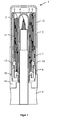
- FIG. 1 shows by way of example the present invention with reference to a cross section through an embodiment of the device according to the invention 1.
- the device 1 has a housing 2, in which a first applicator 3 is arranged.
- the housing 2 is for example made of plastic or metal.
- the housing 2 has a cylindrical shape. Other shapes, for example, with oval or rectangular cross-section, but also conceivable.
- the first applicator 3 is a lipstick lead.
- the lipstick lead 3 is at least partially disposed in the housing 2.
- the lipstick lead 3 is chamfered on the application surface 6, that is to say on the surface which comes into contact with the lips when the lipstick is used.
- the lipstick lead 3 consists of a first cosmetic component.
- This first cosmetic component consists of a material or of a material composition which is suitable and intended to be applied to a lip.
- the lipstick lead 3 preferably has a round cross-section and preferably has a diameter of the order of 8 to 25 mm. In principle, however, the shapes and proportions of the lipstick lead 3 or the first applicator 3 can be chosen freely.
- the device 1 further comprises a second applicator 4.
- the second applicator 4 is tapered conically at the front, that is to say at the side which comes into contact with the lips when the applicator 4 is in use.
- the second applicator 4 is a pen for applying a liquid cosmetic component, for example a liquid lip contour or a lip gloss.
- a liquid cosmetic component for example a liquid lip contour or a lip gloss.
- the pin shape also offers the advantage that the applicator 4 does not have to be immersed in the liquid cosmetic component, but that it is located within a container 11 arranged on the second applicator 4.
- the liquid cosmetic component can be transported by capillary action to the second applicator 4, for example.
- the configuration of the shape of the applicator 4 is basically adapted to the use.
- the second applicator 4, as well as the first applicator 3, may be formed entirely from another cosmetic component.
- the second applicator 4 may be a lip contour pencil lead, by means of which a contour can be applied to the lips to blur the applied lipstick to prevent.
- the device 1 or the second applicator 4 has a cover 5 and the cover 5 is arranged, at least partially, in the first applicator 3.
- the lid 5 separates an inner space in the first applicator 3. In this space, the second applicator 4 is inserted and stowed. When the second applicator 4 is used, it can be removed again from the lid 5, the lid 5 remaining within the first applicator 3. When the second applicator 4 is stowed in the lid 5, the lid 5 ensures that the second applicator 4 does not dry out and does not come into direct contact with the first applicator 3.
- the lid 5 has in this embodiment a round cross-section and preferably has a diameter in the order of 5 to 22 mm. In principle, however, the shapes and the sizes can vary and must be adjusted so that the cover 5 has a similar cross-section and a corresponding size as the second applicator 4.
- the lid 5 is arranged in the first applicator 3, that the opening of the lid 5, that is, the opening from which the second applicator 4 can be removed, on one of the application surface 6 opposite Side is.
- the second applicator 4 is thus removed in this exemplary embodiment downwards.
- the lid 5 extends in the embodiment shown here through the entire first applicator 3 and forms with a foot 9 of the second applicator 4 a closed space within the first applicator 3.
- the lid 5 has an elongated shape and does not cover only the second applicator 4, but also partially arranged on this container 11th
- FIG. 1 embodiment shown further comprises means for the lipstick lead 3 and the first applicator 3, regardless of the second applicator 4, at least partially, to move out of the housing 2 and into the housing 2 inside.
- the means shown here has a rotating mechanism that allows the movement of the lipstick lead 3.
- the rotating mechanism is realized by means of a thread 7 on the inside of the housing 2 and with the aid of a rotary element 10.
- the rotary member 10 is rotatable relative to the housing 2.
- the lipstick lead 3 is arranged in a basket 8.
- the basket 8 has suitable projections 15, which engage in the thread 7 through the rotary member 10.
- the foot 9 of the second applicator 4 is rotatably connected via a connecting element 14 with the rotary member 10. That is, when the second applicator 4 is not in use and stowed in the lid 5, the gripping surface of the rotary member 10 increases around the surface of the foot 9.
- the foot 9 preferably has a height of 12 mm for comfortable use to enable. However, other heights and configurations of the foot 9 are possible, depending on how the second applicator 4 is configured and depending on how the overall design of the device 1 is applied.
- the device 1 can be made very compact, since the rotary member 10 only has to be operated only conditionally and therefore can be made very small.
- the foot 9, which is connectable via the connecting element 14 with the rotary member 10, allows the user to move the lipstick lead 3 comfortably over the rotating mechanism. In this case, the rotary member 10 is rotated relative to the housing 2 together with the connecting element 14 and the foot 9.
- the connecting element 14 can be connected to the rotary element 10, so that the foot 9 does not have to move when the lipstick lead 3 is moved.
- Another alternative may be, for example, that the foot 9 of the second applicator 4 is rotatably connected to the housing 2 and the user can then rotate the foot 9 relative to the rotary member 10 to move the lipstick lead 3. This is particularly advantageous if the user does not want to touch the housing 2, since this example consists of a high gloss material and the user does not want to pollute it.
- the housing 2 may be configured very thin-walled, for example due to a particularly slender embodiment of the device 1, so that it could be at a strong pressure on the housing 2 to a deterioration of the rotation mechanism or the lipstick lead 3 and it is therefore advantageous that the Housing 2 does not need to be touched.
- a connecting element 14 which connects the foot 9 and the rotary member 10, so a direct connection of the two components is possible.
- the foot 9 can be directly connected to the rotary member 10, or the foot 9 can be directly connected to the housing 2.
- the connecting element 14 can be made very compact, so that this example has only the function that rotary member 10 and the foot 9 rotatably connected miteinender.
- FIG. 1 embodiment shown further comprises a housing cover 12, which protects the first applicator 3, when it is not in use.
- FIG. 2 shows cross sections through various components of the device 1, as shown in FIG. 1 ,
- FIG. 2 (a) shows the lid 5 of the second applicator 4 with the connecting element 14.
- the connecting element 14 allows, in the embodiment shown here, that the foot 9 of the second applicator 4 and the rotary member 10 of the rotating mechanism 13 are rotatably connected to each other.
- the lid 5 shown in this embodiment covers not only the second applicator 4 itself but also partially the container 11 disposed on the applicator 4, in which the liquid cosmetic component is for application.
- the lid 5 accordingly has an elongated embodiment. However, other shapes are also conceivable, depending on which part of the second applicator 4 is to be covered and which shape the second applicator 4 has.
- FIG. 2 (b) shows a cross section of the second applicator 4.
- the second applicator 4 at the front that is on the side, which comes into contact with the lips when using the second applicator 4
- is conically tapered is shown.
- other forms are conceivable, depending on which cosmetic component for application is in the container 11 and which cosmetic effect is to be achieved with it.
- a contour pencil will more likely have a tapered applicator 4 with which precise lines can be drawn, whereas other applicators are more likely to have a rectangular cross-section so that more of the liquid cosmetic component can be applied over a larger area.
- the shape of the applicator 4 always depends on the purpose of the cosmetic component for application and where this is applied. This in FIG.
- FIG. 9 which is preferably designed so that the second applicator 4 can stand on this foot 9, when it is removed from the lid 5.
- the foot 9 may for example be designed so that the applicator 4 and the container 11 are interchangeable.
- the foot 9 has, for example, a hole in the middle, in which the applicator 4 and the container 11, which are designed together pin-like, can be introduced.
- the container 11 may be configured in one piece with the foot 9, so that the volume available for the cosmetic component increases.
- the applicator 4 shown with the container 11 the applicator 4 completely consist of a cosmetic component, for example, a Lippenkonturstattmine.
- This mine may for example also be formed like a pin and inserted through a hole in the foot 9.
- the foot 9 instead of a through hole having a receptacle or slip-on that can accommodate different pen-like applicators 4, so that the user can replace, for example, the colors or components.
- FIG. 2 (c) shows the rotating mechanism 13 with the first applicator 3 and the lipstick lead 3 out of the housing 2 and can be moved into the housing 2 into it.
- the rotating mechanism 13 consists of the basket 8, in which the lipstick lead 3 is arranged, the rotary member 10 and the thread 7 on the inside of the housing 2.
- the basket 8 has suitable projections 15, which by the rotary member 10 in the thread 7th on the inside of the housing 2.
- the rotary element 10 is rotatable relative to the housing 2. If the rotary member 10 is rotated relative to the housing 2, the basket 8 is moved with the projections 15 along the thread 7 on the inside of the housing 2 and the basket 8 moves up or down accordingly.
- FIG. 2 shown cross sections of the individual components of FIG. 1 shown inventive device 1, show a further advantage of the inventive Device 1 on.
- the individual component groups are freely selectable by the user. For example, it is possible for the user to select several different lipstick leads 3 with associated turning mechanisms 13. It is also possible, for example, for the user to be able to select a plurality of different second applicators 4, for example a lip gloss or a lip contour pin.
- the device 1 according to the invention therefore not only offers the user a compact device 1 comprising two different applicators 3, 4, but also offers the user great flexibility with regard to the selection of the cosmetic components.
Landscapes
- Cosmetics (AREA)
- Containers And Packaging Bodies Having A Special Means To Remove Contents (AREA)
Description
- Die vorliegende Erfindung betrifft eine neuartige Vorrichtung beinhaltend zwei Applikatoren zum Auftragen von kosmetischen Komponenten.
- Applikatoren sind beispielsweise pinsel-, stift-, röhren-, düsen- oder stabförmige Hilfsmittel zum Auftragen von kosmetischen Komponenten. Ein Beispiel für häufig verwendete und bekannte Applikatoren sind Lippenstifte. Lippenstifte enthalten grundsätzlich mindestens eine kosmetische Komponente. In einer bekannten Ausführungsform eines Lippenstiftes ist die Lippenstiftmine aus mindestens einer kosmetischen Komponente gebildet. Durch das Führen der Lippenstiftmine entlang einer Lippe, verteilt sich diese Komponente auf der Lippe. Beim Lippenstift besteht der Applikator dementsprechend aus der Lippenstiftmine und daher aus der kosmetischen Komponente selbst.
- Darüber hinaus sind viele weitere Applikatoren zum Auftragen von kosmetischen Komponenten bekannt. Ein Beispiel ist ein sogenannter Lippenkonturstift. Ein Lippenkonturstift kann entweder aus einer festen kosmetischen Komponente bestehen, der sogenannten Lippenkonturstiftmine, oder kann in flüssiger Form über einen filzstiftähnlichen Applikator aufgetragen werden. Lippenkonturstifte werden zumeist verwendet, um ein Verlaufen oder Verschmieren des aufgetragenen Lippenstiftes zu verhindern. Ein weiteres Beispiel für einen Applikator ist ein sogenannter Lipgloss, der zumeist aus einer verflüssigten, häufig mit Pflegestoffen und feuchtigkeitsspendenden Stoffen angereicherten Lippenfarbe besteht und mittels eines pinselähnlichen Applikators aufgetragen wird. Des Weiteren sind andere kosmetische Produkte und verschiedenste dafür vorgesehene Applikatoren bekannt.
- Üblicherweise verwendet ein Benutzer zumeist mehrere verschiedene Applikatoren zum Auftragen verschiedener kosmetischer Komponenten. So verwendet ein Benutzer beispielsweise zunächst einen Lippenstift und zeichnet anschließend die Lippenkontur mit einem Lippenkonturstift nach. Auch kann ein Benutzer beispielsweise ein transparentes Lipgloss verwenden, um dem aufgetragenen Lippenstift mehr Glanz zu verleihen, wobei der Lipgloss auf den schon aufgetragenen Lippenstift mittels eines pinselähnlichen Applikators aufgetupft wird und durch ein anschließendes kurzes Zusammenpressen der Lippen verteilt wird.
- Für ein komplettes Make-up beziehungsweise für die Pflege der Lippen oder anderer Gesichtpartien muss der Benutzer dementsprechend nicht nur mehrerer Gegenstände mit führen, sondern diese auch nacheinander handhaben.
- Eine Mehrfachapplikatorvorrichtung, welche dem Benutzer die Handhabung dadurch erleichtern, dass sie die Funktionalität von mehreren Gegenständen in einem Gegenstand vereint, ist beispielsweise aus
US 2002/0071707 A1 bekannt.US 2002/0071707 A1 zeigt ein an zwei Enden offenes Gehäuse mit Aufsteckhülsen. Auf diese Hülsen können Applikatoren für kosmetische Komponenten aufgesteckt werden. Hierbei kann es sich beispielsweise um Lippenstifte mit unterschiedlichen Farben oder um einen Lippenstift und einen Lipgloss handeln. Die Applikatoren selbst werden dabei in die Hülsen aufgesteckt und mittels Deckeln verschlossen. Die Deckel schützen die Applikatoren, wenn diese nicht in Benutzung sind. Bei Applikatoren zum Auftragen einer flüssigen kosmetischen Komponente, dient der Deckel des Applikators als Behältnis für die flüssige kosmetische Komponente. In diesem Fall taucht der Applikator somit in die flüssige Komponente ein. Bei einem Lipgloss wird beispielsweise der pinselähnliche Applikator in die Aufsteckhülse gesteckt, der Deckel mit dem flüssigen Lipgloss befüllt und dann der Applikator mit dem Deckel verschlossen. Die inUS 2002/0071707 A1 gezeigte Vorrichtung hat allerdings den Nachteil, dass durch die beschriebene Verwendung des Gehäuses, die gesamte Vorrichtung größer ist, als die beiden Applikatoren zusammen. Das bedeutet, dass der Benutzer zwar nur einen Gegenstand mitführen muss, dieser aber größer ist, als die zwei einzelnen Gegenstände. Gerade in der Situation in der der Benutzer nur eine kleine Handtasche mit sich führt oder der Gegenstand nur in der Hosentasche Platz findet, sind die größeren Außenmaße des Gegenstandes unvorteilhaft. Des Weiteren muss der Benutzer bei der Handhabung der Vorrichtung immer darauf achten, dass die Vorrichtung in der richtigen Position geöffnet wird, um zu verhindern, dass beim Öffnen beispielsweise Flüssigkeit aus dem Deckel austritt. - Eine Vorrichtung gemäß dem Oberbegriff des Anspruchs 1 ist aus der
US 2 964 045 A bekannt. - Es stellt sich daher die Aufgabe, eine Vorrichtung bereitzustellen, die die vorher benannten Nachteile nicht aufweist und insbesondere sehr kompakt ist. Erfindungsgemäß wird diese Aufgabe durch eine Vorrichtung gemäß dem unabhängigen Anspruch 1 gelöst. Vorteilhafte Ausgestaltungen ergeben sich aus den Unteransprüchen.
- Die erfindungsgemäße Vorrichtung weist ein Gehäuse, einen ersten Applikator zum Auftragen mindestens einer kosmetischen Komponente und einen zweiten Applikator zum Auftragen von mindestens einer kosmetischen Komponente auf. Erfindungsgemäß ist in dem Gehäuse zumindest teilweise der erste Applikator angeordnet. Dieser erste Applikator besteht aus einer ersten kosmetischen Komponente zum Auftragen, das heißt der Benutzer kann die erste Komponente beispielsweise auf eine Lippe auftragen. Dabei werden an der mit der Lippe in Kontakt tretenden Fläche des Applikators, Teile der kosmetischen Komponente abgetragen und auf die Lippe transferiert. Der erste Applikator kann beispielsweise ein Lippenstift sein, der aus einer Lippenstiftmine besteht. Die Lippenstiftmine selbst ist in diesem Fall der erste Applikator. Erfindungsgemäß ist im ersten Applikator ein Deckel angeordnet und in diesem Deckel ist wiederum der zweite Applikator entnehmbar angeordnet. Der Deckel ist eine Wand, die den Bereich des ersten Applikators von dem Bereich des zweiten Applikators abgrenzt. Durch den Deckel wird ein zumindest einseitig geschlossener Raum gebildet, in dem der zweite Applikator angeordnet sein kann. Der Deckel schützt dadurch den zweiten Applikator nicht nur vorm austrocknen, sondern stellt auch eine Abgrenzung des Applikators von der Umgebung dar. Dieses ist insbesondere deshalb nötig, da erfindungsgemäß der Deckel des zweiten Applikators, zumindest teilweise, in dem ersten Applikator angeordnet ist. Der Deckel erstreckt sich dabei durch einen wesentlichen Teil des ersten Applikators. Der Deckel bildet einen Raum innerhalb des ersten Applikators aus, der von dem ersten Applikator getrennt ist und in welchen der zweite Applikator einführbar und in welchem der zweite Applikator verstaubar ist. Je nach Länge des ersten Applikators und je nachdem wie weit der Deckel im ersten Applikator angeordnet ist, wird vom Deckel nicht nur der zweite Applikator sondern auch an diesem angeordnete Teile bedeckt. Der in dem Deckel verstaute zweite Applikator und die eventuellen weiteren Teile sind erfindungsgemäß zur Benutzung aus dem Deckel entnehmbar. Der Deckel selbst kann dabei im ersten Applikator verbleiben. Ist der zweite Applikator nicht in Benutzung, so kann er wieder im Deckel innerhalb des ersten Applikators verstaut werden. Mit Hilfe des Deckels kann der zweite Applikator somit im ersten Applikator angeordnet werden, ohne dass die beiden Applikatoren dabei in direkten Kontakt treten.
- Durch die erfindungsgemäße Vorrichtung wird dem Benutzer zum ersten Mal eine Vorrichtung bereitgestellt, in welcher zwei Applikatoren zum Auftragen von kosmetischen Komponenten sehr kompakt angeordnet werden können und die Vorrichtung dem Benutzer trotzdem eine einfache Handhabung der beiden Applikatoren gewährleistet. Die kompakte Ausgestaltung der Vorrichtung wird dadurch ermöglicht, dass sich der zweite Applikator zumindest teilweise in dem ersten Applikator befindet und von diesem durch den Deckel getrennt ist. Durch diese klare Trennung kommt der zweite Applikator nicht in direkte Berührung mit dem ersten Applikator und kann nicht verschmutzt werden. Die kompakte Anordnung der Applikatoren ineinander hat den Vorteil, dass der Benutzer nur einen sehr kompakten Gegenstand mit sich führen muss aber trotzdem in der Lage ist, zwei unterschiedliche kosmetische Komponenten aufzutragen. Dabei ist die Größe der Vorrichtung mit den zwei ineinander angeordneten Applikatoren nur unwesentlich größer als ein einzelner Applikator für sich allein genommen. Ist der erste Applikator beispielsweise ein Lippenstift und der zweite Applikator ein Konturstift, zum Auftragen einer flüssigen Komponente, so ist die Größe der erfindungsgemäßen Vorrichtung in der beide Applikatoren ineinander angeordnet sind nicht viel größer, als der Lippenstift für sich allein genommen.
- Gemäß einer bevorzugten Ausführungsform der vorliegenden Erfindung, ist der zweite Applikator an einer Seite aus der Vorrichtung entnehmbar. Dies ist die Seite, die der Fläche zum Auftragen der kosmetischen Komponente des ersten Applikators gegenüber liegt. Also gegenüberliegend einer Fläche, an der Teile des ersten Applikators abgetragen werden und beispielsweise auf eine Lippe aufgetragen werden. Nach der Benutzung kann der zweite Applikator dann wieder in dem Deckel verstaut werden. Durch diese Entnahme-/Einführrichtung wird die Handhabung der Vorrichtung für den Benutzer dadurch wesentlich erleichtert, dass die Vorrichtung zur Verwendung der beiden Applikatoren nicht gedreht werden muss. So kann beispielsweise die obere Seite der Vorrichtung verwendet werden, um mittels des ersten Applikators einen Lippenstift aufzutragen und an der Unterseite des Lippenstiftes kann der zweite Applikator entnommen/eingeführt werden. Dadurch entfällt eine Drehung der Vorrichtung, wie es beispielsweise bei bekannten Mehrfachapplikatorvorrichtungen nötig ist.
- Vorzugsweise weist die Vorrichtung auch Mittel auf, um den ersten Applikator unabhängig von dem zweiten Applikator, zumindest teilweise, aus dem Gehäuse heraus und in das Gehäuse hinein zu bewegen. Dabei ist das Mittel vorzugsweise durch einen Drehmechanismus realisiert. Vorzugsweise weist der Drehmechanismus ein Drehelement auf, wobei das Drehelement relativ zum Gehäuse drehbar ist. Das Drehelement ist somit nicht fest mit dem Gehäuse verbunden. Des Weiteren weist der Drehmechanismus vorzugsweise ein Gewinde auf. Dieses Gewinde kann entweder an der Innenseite des Gehäuses angeordnet sein oder an der Außenseite des Deckels, das heißt an der Seite des Deckels, die in direkter Verbindung mit dem ersten Applikator steht. Mit Hilfe dieses Drehmechanismus kann das Bewegen des ersten Applikators auf einfache Weise, ohne platzraubende und komplizierte Bauteile realisiert werden.
- Vorzugsweise ist der erste Applikator in einem Korb angeordnet. Dieser Korb wird in einer bevorzugten Ausführungsform mit Hilfe des Gewindes und des Drehelementes hoch und runter bewegt, um den ersten Applikator je nach Wunsch aus dem Gehäuse heraus oder in das Gehäuse hinein zu bewegen. Der Korb weist dabei vorzugsweise eine Öffnung in der Mitte auf, durch die der Deckel beziehungsweise der zweite Applikator geführt werden kann. Die Öffnung ermöglicht es, dass der Korb entlang des zweiten Applikators geführt werden kann.
- In einer bevorzugten Ausführungsform ist an dem zweiten Applikator ein Fuß angeordnet. Der Fuß kann beispielsweise aus Metall oder Kunststoff sein. Der Fuß hat vorzugsweise den gleichen oder einen ähnlichen Querschnitt wie das Gehäuse der erfindungsgemäßen Vorrichtung, so dass der Fuß des zweiten Applikators, wenn dieser im Deckel verstaut ist, eine Basis der erfindungsgemäßen Vorrichtung bildet, auf der beispielsweise die Vorrichtung stehen kann. Des Weiteren kann der Fuß so ausgestaltet sein, dass er eine Aufnahme für verschiedene Applikatoren und andere daran angeordnete Teile aufweist. Durch diese Aufnahme ist es dem Benutzer dann möglich, den Applikator zu wechseln.
- Der Fuß ist vorzugsweise drehfest mit dem Drehelement des Drehmechanismus verbindbar, so dass der Drehmechanismus sehr kompakt ausgestaltet werden kann, dem Benutzer jedoch immer noch eine komfortable Handhabung ermöglicht wird. Wenn der Fuß drehfest mit dem Drehelement verbindbar ist, braucht der Benutzer nicht mehr am Drehelement selbst anzugreifen, um den ersten Applikator aus dem Gehäuse heraus beziehungsweise in dieses hinein zu bewegen. Stattdessen kann der Benutzer am Fuß angreifen. In dieser Ausführungsform wird der Fuß zusammen mit dem Drehelement relativ zum Gehäuse gedreht, um den ersten Applikator in das Gehäuse hinein beziehungsweise aus dem Gehäuse heraus zu bewegen. Die drehfeste Verbindung kann dabei beispielsweise durch ineinander greifende Zahnungen realisiert werden. Aber auch andere dem Fachmann bekannte drehfeste Verbindungen sind denkbar. Dabei ist nur darauf zu achten, dass die Komplexität der Verbindung nicht die Handhabung beeinträchtigt. Der Fuß des zweiten Applikators muss einfach mit dem Drehelement verbindbar sein und sich auch schnell wieder lösen lassen, um die einfache Benutzung des zweiten Applikators zu gewährleisten. Dadurch dass der Fuß mit dem Drehelement verbindbar ist, kann das Drehelement selbst sehr kompakt ausgestaltet werden, so dass die Größe der Vorrichtung insgesamt sehr klein gehalten werden kann.
- Alternativ kann aber auch das Gehäuse der Vorrichtung drehfest mit dem Fuß des zweiten Applikators verbindbar sein. Bei dieser Ausführungsform führt eine Drehung des Fußes auch zu einer Relativbewegung zwischen Drehelement und Gehäuse. Diese Ausgestaltung erlaubt es dem Benutzer am Drehelement und am Fuß anzugreifen, ohne dass das Gehäuse berührt werden muss. Dieses hat beispielsweise bei Metallgehäusen oder bei hochglänzenden Gehäusen den Vorteil, dass diese nicht verschmutzt werden. Dass das Gehäuse nicht direkt berührt werden muss, um den ersten Applikator aus dem Gehäuse heraus beziehungsweise in dieses hinein zu bewegen, hat auch den Vorteil, dass das Gehäuse sehr dünnwandig ausgestaltet werden kann, da nicht die Gefahr besteht, dass es durch zu starken Druck zusammengedrückt wird und dadurch entweder der Applikator und/oder der Drehmechanismus beeinträchtigt wird. Auch hier sollte der Fuß des zweiten Applikators einfach mit dem Gehäuse verbindbar sein und sich auch schnell wieder lösen lassen, um die einfache Benutzung des zweiten Applikators zu gewährleisten.
- In einer weiteren alternativen Ausführungsform können der Fuß und das Drehelement beziehungsweise das Gehäuse aber auch nicht-drehfest miteinander verbunden sein. Hierdurch wird dem Benutzer zum Beispiel die Zweiteiligkeit der Vorrichtung zusätzlich verdeutlicht.
- In einer weiteren bevorzugten Ausführungsform besteht der zweite Applikator aus einer zweiten kosmetischen Komponente zum Auftragen, beispielsweise aus einer Lippenkonturstiftmine. Die Lippenkonturstiftmine ist dabei von dem Deckel umschlossen, so dass sie ohne direkt in Kontakt mit dem ersten Applikator zu treten, in dem ersten Applikator angeordnet werden kann. Bei der Verwendung der Lippenkonturstiftmine verbleibt der Deckel im ersten Applikator und bildet dort den Raum aus, in welchem die Lippenkonturstiftmine nach Benutzung wieder verstaut werden kann. Dieses hat des Weiteren den Vorteil, dass die Lippenkonturstiftmine vorm austrocknen geschützt wird.
- Alternativ kann es sich bei dem zweiten Applikator auch um einen Stift zum Auftragen einer flüssigen kosmetischen Komponente handeln. Dabei kann sich beispielsweise die flüssige kosmetische Komponente in einem Behälter befinden, der an dem zweiten Applikator angeordnet ist. Der Behälter kann dabei beispielsweise auch teilweise in dem Deckel angeordnet sein. Auch kann der Fuß des zweiten Applikators den Behälter für die flüssige kosmetische Komponente beinhalten. Alternativ können der Fuß und der Behälter auch einstückig ausgestaltet sein. Auch können beispielsweise der Fuß und der Behälter so zusammenwirken, dass wenn der Fuß zusammengedrückt wird, sich der Druck im Behälter erhöht und die flüssige kosmetische Komponente am Applikator austreten kann. Zwischen Applikator und Behälter kann dabei beispielsweise eine Art Rückschlagventil angeordnet sein, das nur bei entsprechendem Druck im Behälter, die flüssige kosmetische Komponente zum Applikator durchlässt. Dieses hat den Vorteil, dass wenn der Applikator nicht verwendet wird und im Deckel verstaut ist, ein versehentlich ausgeübter Druck nicht dazu führt, dass die flüssige kosmetische Komponente am Applikator austreten kann und sich im Deckel ansammeln kann. Auch können zwischen dem Behälter und dem Applikator andere dem Fachmann bekannte Mechanismen angeordnet sein, die die flüssige kosmetische Komponente im Behälter zurückhalten, solange der Applikator nicht in Verwendung ist.
- Alternativ kann es sich bei dem zweiten Applikator auch um einen sogenannten Automatikstift handeln, der vor und zurück gedreht werden kann. Bei einem derartigen Automatikstift sind der Fuß und das Drehelement beziehungsweise das Gehäuse vorzugsweise nicht-drehfest miteinander verbunden. Die Mine des Automatikstiftes kann dann durch das Drehen des Fußes und durch Festhalten des Drehelementes beziehungsweise des Gehäuses hoch und runter gedreht werden. Alternativ kann es sich auch bei dem zweiten Applikator um einen Pinsel handeln mit dem zum Beispiel etwas aufgetragen werden kann oder die durch den ersten Applikator aufgetragene kosmetische Komponente nachbearbeitet werden kann.
- In einer bevorzugten Ausführungsform handelt es sich bei dem ersten Applikator um eine Lippenstiftmine.
- Gemäß einer bevorzugten Ausführungsform der vorliegenden Erfindung weist die erfindungsgemäße Vorrichtung auch einen Gehäusedeckel auf. Mit Hilfe des Gehäusedeckels wird die Vorrichtung, insbesondere der erste Applikator geschützt, wenn die Vorrichtung gerade nicht benutzt wird.
- Vorzugsweise handelt es sich beim ersten Applikator um einen Lippenstift und bei dem zweiten Applikator um einen im Lippenstift angeordneten stiftähnlichen Applikator zum Auftragen einer flüssigen kosmetischen Komponente.
- Weitere Vorteile und Merkmale der Erfindung sind der nachfolgenden detaillierten Beschreibung zu entnehmen, in welcher die Erfindung detailliert und in Bezug auf die in den beigefügten Zeichnungen dargestellten Ausführungsbeispiele beschrieben wird.
- In den Zeichnungen zeigt:
- Fig. 1
- einen Querschnitt durch eine erfindungsgemäße Vorrichtung beinhaltend zwei Applikatoren; und
- Fig. 2
- Querschnitte durch verschiedene Bauteile der erfindungsgemäßen Vorrich- tung, wie gezeigt in
Fig. 1 . -
Figur 1 zeigt beispielhaft die vorliegende Erfindung anhand eines Querschnittes durch eine Ausführungsform der erfindungsgemäßen Vorrichtung 1. Die Vorrichtung 1 weist ein Gehäuse 2 auf, in welchem ein erster Applikator 3 angeordnet ist. Das Gehäuse 2 ist dabei beispielsweise aus Kunststoff oder Metall. In dem gezeigten Beispiel hat das Gehäuse 2 eine zylindrische Form. Andere Formen, beispielsweise mit ovalem oder rechteckigem Querschnitt, sind jedoch auch denkbar. - In dem in
Figur 1 gezeigtem Ausführungsbeispiel ist der erste Applikator 3 eine Lippenstiftmine. Die Lippenstiftmine 3 ist zumindest teilweise in dem Gehäuse 2 angeordnet. Zur Veranschaulichung ist ein Ausführungsbeispiel gezeigt, bei dem die Lippenstiftmine 3 an der Auftragsfläche 6, das heißt an der Fläche, die bei Benutzung des Lippenstiftes mit den Lippen in Kontakt kommt, abgeschrägt ist. Die Lippenstiftmine 3 besteht aus einer ersten kosmetischen Komponente. Diese erste kosmetische Komponente besteht aus einem Material oder aus einer Materialzusammensetzung, welche geeignet und bestimmt ist, auf eine Lippe aufgetragen zu werden. Die Lippenstiftmine 3 weist vorzugsweise einen runden Querschnitt auf und hat vorzugsweise einen Durchmesser in der Größenordnung von 8 bis 25 mm. Grundsätzlich können die Formen und Größenverhältnisse der Lippenstiftmine 3 beziehungsweise des ersten Applikators 3 jedoch frei gewählt werden. - In dem in
Figur 1 gezeigtem Ausführungsbeispiel weist die Vorrichtung 1 weiter einen zweiten Applikator 4 auf. Zur Veranschaulichung ist ein Ausführungsbeispiel gezeigt, bei dem der zweite Applikator 4 an der Vorderseite, das heißt an der Seite, die bei Benutzung des Applikators 4 mit den Lippen in Kontakt kommt, konisch zugespitzt ist. In dem hier gezeigten Ausführungsbeispiel ist der zweite Applikator 4 ein Stift zum Auftragen einer flüssigen kosmetischen Komponente, beispielsweise einer flüssigen Lippenkontur oder eines Lipgloss. Durch die stift-ähnliche Form des zweiten Applikators 4 kann ein präzises Auftragen gewährleistet werden. Grundsätzlich bietet die Stiftform auch den Vorteil, dass der Applikator 4 nicht in die flüssige kosmetische Komponente eingetaucht werden muss, sondern sich diese innerhalb eines an dem zweiten Applikators 4 angeordneten Behälters 11 befindet. Ähnlich wie bei einem Filzstift kann die flüssige kosmetische Komponente beispielsweise durch Kapillarwirkung zum zweiten Applikator 4 transportiert werden. Die Ausgestaltung der Form des Applikators 4 ist grundsätzlich der Verwendung anzupassen. Alternativ kann der zweite Applikator 4, wie auch der erste Applikator 3, vollständig aus einer weiteren kosmetischen Komponente geformt sein, beispielsweise kann der zweite Applikator 4 eine Lippenkonturstiftmine sein, mittels der eine Kontur auf die Lippen aufgetragen werden kann, um ein Verwischen des aufgetragenen Lippenstiftes zu verhindern. - In dem in
Figur 1 gezeigtem Ausführungsbeispiel weist die Vorrichtung 1 beziehungsweise der zweite Applikator 4 einen Deckel 5 auf und der Deckel 5 ist, zumindest teilweise, in dem ersten Applikator 3 angeordnet. Der Deckel 5 trennt einen inneren Raum in dem ersten Applikator 3 ab. In diesen Raum ist der zweite Applikator 4 einführbar und verstaubar. Bei Benutzung des zweiten Applikators 4 kann dieser aus dem Deckel 5 wieder entnommen werden, wobei der Deckel 5 innerhalb des ersten Applikators 3 verbleibt. Wenn der zweite Applikator 4 in dem Deckel 5 verstaut ist, sorgt der Deckel 5 dafür, dass der zweite Applikator 4 nicht austrocknet und nicht in direkten Kontakt mit dem ersten Applikator 3 kommt. Der Deckel 5 weist in diesem Ausführungsbeispiel einen runden Querschnitt auf und hat vorzugsweise einen Durchmesser in der Größenordung von 5 bis 22 mm. Grundsätzlich können aber die Formen und Größenordnungen variieren und sind so anzupassen, dass der Deckel 5 einen ähnlichen Querschnitt und eine korrespondierende Größe, wie der zweite Applikator 4 hat. - In dem in
Figur 1 gezeigtem Ausführungsbeispiel ist der Deckel 5 so im ersten Applikator 3 angeordnet, dass die Öffnung des Deckels 5, das heißt die Öffnung aus der der zweite Applikator 4 entnehmbar ist, an einer der Auftragsfläche 6 gegenüberliegenden Seite liegt. Der zweite Applikator 4 ist in diesem Ausfiihrungsbeispiel also nach unten hin entnehmbar. Der Deckel 5 erstreckt sich in dem hier gezeigten Ausführungsbeispiel durch den gesamten ersten Applikator 3 und bildet mit einem Fuß 9 des zweiten Applikators 4 einen geschlossenen Raum innerhalb des ersten Applikators 3. In dem hier gezeigten Ausführungsbeispiel hat der Deckel 5 eine längliche Form und bedeckt nicht nur den zweiten Applikator 4, sondern auch teilweise den an diesem angeordneten Behälter 11. - Das in
Figur 1 gezeigte Ausführungsbeispiel weist weiter Mittel auf, um die Lippenstiftmine 3 beziehungsweise den ersten Applikator 3 unabhängig von dem zweiten Applikator 4, zumindest teilweise, aus dem Gehäuse 2 heraus und in das Gehäuse 2 hinein zu bewegen. Das hier gezeigte Mittel weist einen Drehmechanismus auf, der die Bewegung der Lippenstiftmine 3 ermöglicht. Grundsätzlich weiß der Fachmann allerdings, dass auch ein anderer Mechanismus wie beispielsweise ein Schiebemechanismus möglich ist. In dem hier gezeigten Ausführungsbeispiel ist der Drehmechanismus mit Hilfe eines Gewindes 7 an der Innenseite des Gehäuses 2 und mit Hilfe eines Drehelementes 10 realisiert. Dabei ist das Drehelement 10 relativ zum Gehäuse 2 drehbar. In dem gezeigten Ausführungsbeispiel ist die Lippenstiftmine 3 in einem Korb 8 angeordnet. Der Korb 8 weist geeignete Vorsprünge 15 auf, welche durch das Drehelement 10 in das Gewinde 7 greifen. Wird nun das Drehelement 10 relativ zum Gehäuse 2 gedreht, so wird der Korb 8 entlang des Gewindes 7 nach oben beziehungsweise unten bewegt. Um die Drehbewegung für den Benutzer zu vereinfachen, ist in dem hier gezeigten Ausführungsbeispiel der Fuß 9 des zweiten Applikators 4 über ein Verbindungselement 14 mit dem Drehelement 10 drehfest verbunden. Das heißt, wenn der zweite Applikator 4 nicht in Benutzung ist und im Deckel 5 verstaut ist, so erhöht sich die Grifffläche des Drehelementes 10 um die Oberfläche des Fußes 9. Der Fuß 9 hat dabei vorzugsweise eine Höhe von 12 mm, um eine komfortable Benutzung zu ermöglichen. Allerdings sind auch andere Höhen und Ausgestaltungen des Fußes 9 möglich, je nachdem wie der zweite Applikator 4 ausgestaltet ist und je nachdem wie die Gesamtausgestaltung der Vorrichtung 1 angelegt ist. Durch die Verbindung des Drehelementes 10 mit dem Fuß 9 kann die Vorrichtung 1 sehr kompakt hergestellt werden, da das Drehelement 10 nur bedingt allein bedienbar sein muss und daher sehr klein ausgestaltet werden kann. Der Fuß 9, der über das Verbindungselement 14 mit dem Drehelement 10 verbindbar ist, ermöglicht dem Benutzer die Lippenstiftmine 3 komfortabel über den Drehmechanismus zu bewegen. Dabei wird das Drehelement 10 zusammen mit dem Verbindungselement 14 sowie dem Fuß 9 relativ zum Gehäuse 2 gedreht. - Alternativ kann auch nur das Verbindungselement 14 mit dem Drehelement 10 verbunden sein, so dass der Fuß 9 sich nicht mitbewegen muss, wenn die Lippenstiftmine 3 bewegt wird. Eine weitere Alternative kann beispielsweise sein, dass der Fuß 9 des zweiten Applikators 4 mit dem Gehäuse 2 drehfest verbindbar ist und der Benutzer dann den Fuß 9 relativ zum Drehelement 10 drehen kann, um die Lippenstiftmine 3 zu bewegen. Dieses ist besonders dann vorteilhaft, wenn der Benutzer das Gehäuse 2 nicht anfassen möchte, da dieses beispielsweise aus einem hoch glänzenden Material besteht und der Benutzer dieses nicht verschmutzen möchte. Auch kann das Gehäuse 2 beispielsweise aufgrund einer besonders schlanken Ausgestaltung der Vorrichtung 1 sehr dünnwandig ausgestaltet sein, so dass es bei einem zu starkem Druck auf das Gehäuse 2 zu einer Beeinträchtigung des Drehmechanismus beziehungsweise der Lippenstiftmine 3 kommen könnte und es deshalb vorteilhaft ist, dass das Gehäuse 2 nicht berührt werden muss.
- Auch wenn in dem hier gezeigten Ausführungsbeispiel ein Verbindungselement 14 gezeigt ist, welches den Fuß 9 sowie das Drehelement 10 verbindet, so ist auch eine direkte Verbindung der beiden Bauteile möglich. Dabei kann beispielsweise der Fuß 9 direkt mit dem Drehelement 10 verbindbar sein, oder der Fuß 9 kann direkt mit dem Gehäuse 2 verbindbar sein. Alternativ kann auch das Verbindungselement 14 sehr kompakt ausgestaltet sein, so dass dieses beispielsweise nur die Funktion hat, dass Drehelement 10 und den Fuß 9 drehfest miteinender zu verbinden.
- Das in
Figur 1 gezeigte Ausführungsbeispiel weist weiter einen Gehäusedeckel 12 auf, welcher den ersten Applikator 3 schützt, wenn dieser nicht in Benutzung ist. -
Figur 2 zeigt Querschnitte durch verschiedene Bauteile der Vorrichtung 1, wie gezeigt inFigur 1 . -
Figur 2 (a) zeigt den Deckel 5 des zweiten Applikators 4 mit dem Verbindungselement 14. Das Verbindungselement 14 ermöglicht, in der hier gezeigten Ausführungsform, dass der Fuß 9 des zweiten Applikators 4 und das Drehelement 10 des Drehmechanismus 13 drehfest miteinander verbindbar sind. Der in diesem Ausführungsbeispiel gezeigte Deckel 5 bedeckt nicht nur den zweiten Applikator 4 selbst sondern auch teilweise den an dem Applikator 4 angeordneten Behälter 11, in welchem sich die flüssige kosmetische Komponente zum Auftragen befmdet. Der Deckel 5 hat dementsprechend eine längliche Ausgestaltungsform. Allerdings sind auch andere Formen denkbar, je nachdem welcher Teil des zweiten Applikators 4 abgedeckt werden soll und welche Form der zweite Applikator 4 aufweist. -
Figur 2 (b) zeigt einen Querschnitt des zweiten Applikators 4. Zur Veranschaulichung ist ein Ausführungsbeispiel gezeigt, bei dem der zweite Applikator 4 an der Vorderseite, das heißt an der Seite, die bei Benutzung des zweiten Applikators 4 mit den Lippen in Kontakt kommt, konisch zugespitzt ist. Hier sind aber auch andere Formen denkbar, je nachdem welche kosmetische Komponente zum Auftragen sich in dem Behälter 11 befindet und welcher kosmetische Effekt damit erzielt werden soll. So wird ein Konturstift eher einen konisch zulaufenden Applikator 4 aufweisen mit welchem präzise Linen gezogen werden können, wohingegen andere Applikatoren eher einen rechteckigen Querschnitt aufweisen, so dass mehr der flüssigen kosmetischen Komponente auf eine größere Fläche aufgetragen werden kann. Die Form des Applikators 4 richtet sich dabei immer nach dem Zweck der kosmetischen Komponente zum Auftragen und wo diese aufgetragen wird. Das inFigur 2 (b) gezeigte Ausführungsbeispiel weist weiter einen Fuß 9 auf, welcher vorzugsweise so ausgestaltet ist, dass der zweite Applikator 4 auf diesem Fuß 9 stehen kann, wenn er aus dem Deckel 5 entnommen ist. Dabei kann der Fuß 9 beispielsweise so ausgestaltet sein, dass der Applikator 4 und der Behälter 11 auswechselbar sind. In dem hier gezeigten Ausführungsbeispiel hat der Fuß 9 beispielsweise ein Loch in der Mitte, in welches der Applikator 4 und der Behälter 11, die zusammen stiftartig ausgestaltet sind, eingeführt werden können. Alternativ kann aber auch der Behälter 11 einstückig mit dem Fuß 9 ausgestaltet sein, so dass sich das Volumen, welches für die kosmetische Komponente zur Verfügung steht, vergrößert. Auch kann anstelle des gezeigten Applikators 4 mit dem Behälter 11, der Applikator 4 komplett aus einer kosmetischen Komponente bestehen, beispielsweise aus einer Lippenkonturstiftmine. Diese Mine kann beispielsweise auch stiftartig ausgeformt sein und durch ein Loch im Fuß 9 einführbar sein. Auch kann beispielsweise der Fuß 9 anstelle eines durchgängigen Loches eine Aufnahme oder Aufsteckhülse aufweisen, die verschiedene stiftartige Applikatoren 4 aufnehmen kann, so das der Benutzer beispielsweise die Farben oder die Komponenten auswechseln kann. -
Figur 2 (c) zeigt den Drehmechanismus 13 mit dem der erste Applikator 3 beziehungsweise die Lippenstiftmine 3 aus dem Gehäuse 2 heraus und in das Gehäuse 2 hinein bewegt werden kann. Der Drehmechanismus 13 besteht dabei aus dem Korb 8, in welchem die Lippenstiftmine 3 angeordnet ist, dem Drehelement 10 und dem Gewinde 7 an der Innenseite des Gehäuses 2. Der Korb 8 weist geeignete Vorsprünge 15 auf, welche durch das Drehelement 10 in das Gewinde 7 an der Innenseite des Gehäuses 2 greifen. Das Drehelement 10 ist relativ zum Gehäuse 2 drehbar. Wird das Drehelement 10 relativ zum Gehäuse 2 gedreht, so wird der Korb 8 mit den Vorsprüngen 15 entlang des Gewindes 7 an der Innenseite des Gehäuses 2 bewegt und der Korb 8 bewegt sich entsprechend hinauf beziehungsweise herunter. - Die in
Figur 2 gezeigten Querschnitte der einzelnen Bauteile der inFigur 1 gezeigten erfindungsgemäßen Vorrichtung 1, zeigen einen weiteren Vorteil der erfmdungsgemäßen Vorrichtung 1 auf. Die einzelnen Bauteilgruppen sind vom Benutzer frei wählbar. So ist es beispielsweise möglich, dass der Benutzer mehrere unterschiedliche Lippenstiftminen 3 mit dazugehörigen Drehmechanismen 13 auswählen kann. Auch ist es beispielsweise möglich, dass der Benutzer mehrere unterschiedliche zweite Applikatoren 4 auswählen kann, beispielsweise einen Lipgloss oder einen Lippenkonturstift. Mittels des Verbindungsstückes 14 lassen sich diese unterschiedlichen Applikatoren 3, 4 miteinander in der inFigur 1 gezeigten Weise zu einer erfindungsgemäßen Vorrichtung 1 kombinieren. Die erfindungsgemäße Vorrichtung 1 bietet daher dem Benutzer nicht nur eine kompakte Vorrichtung 1 beinhaltend zwei unterschiedliche Applikatoren 3, 4, sondern bietet dem Benutzer auch eine große Flexibilität in Bezug auf die Auswahl der kosmetischen Komponenten.
Claims (15)
- Vorrichtung (1) zum Auftragen von kosmetischen Komponenten, aufweisend:ein Gehäuse (2);einen ersten Applikator (3) aus einer kosmetischen Komponente zum Auftragen, wobei der erste Applikator (3) zumindest teilweise in dem Gehäuse (2) angeordnet ist;einen zweiten Applikator (4) zum Auftragen einer kosmetischen Komponente;
dadurch gekennzeichnet, dassdie Vorrichtung einen in dem ersten Applikator (3) zumindest teilweise angeordneten Deckel (5) aufweist undder zweite Applikator (4) in dem Deckel (5) entnehmbar angeordnet ist. - Vorrichtung (1) nach Anspruch 1, dadurch gekennzeichnet, dass der zweite Applikator (4) an einer Seite aus der Vorrichtung (1) entnehmbar ist, die einer Auftragsfläche (6) zum Auftragen der kosmetischen Komponente des ersten Applikators (3) gegenüberliegt.
- Vorrichtung (1) nach einem der vorhergehenden Ansprüche, dadurch gekennzeichnet, dass die Vorrichtung (1) weiter Mittel aufweist, um den ersten Applikator (3) unabhängig von dem zweiten Applikator (4) zumindest teilweise aus dem Gehäuse (2) heraus und in das Gehäuse (2) hinein zu bewegen.
- Vorrichtung (1) nach Anspruch 3, dadurch gekennzeichnet, dass das Mittel einen Drehmechanismus (13) aufweist.
- Vorrichtung (1) nach Anspruch 4, dadurch gekennzeichnet, dass der Drehmechanismus (13) ein Drehelement (10) aufweist, wobei das Drehelement (10) relativ zum Gehäuse (2) drehbar ist.
- Vorrichtung (1) nach Anspruch 5, dadurch gekennzeichnet, dass an dem zweiten Applikator (4) ein Fuß (9) angeordnet ist.
- Vorrichtung (1) nach Anspruch 6, dadurch gekennzeichnet, dass das Drehelement (10) drehfest mit dem Fuß (9) des zweiten Applikators (4) verbindbar ist.
- Vorrichtung (1) nach Anspruch 6, dadurch gekennzeichnet, dass das Gehäuse (2) drehfest mit dem Fuß (9) des zweiten Applikators (4) verbindbar ist.
- Vorrichtung (1) nach einem der Ansprüche 4 bis 8, dadurch gekennzeichnet, dass der Drehmechanismus (13) ein Gewinde (7) an der Innenseite des Gehäuses (2) aufweist.
- Vorrichtung (1) nach einem der Ansprüche 4 bis 9, dadurch gekennzeichnet, dass der erste Applikator (3) in einem Korb (8) angeordnet ist.
- Vorrichtung (1) nach einem der Ansprüche 1 bis 10, dadurch gekennzeichnet, dass der zweite Applikator (4) aus einer zweiten kosmetischen Komponente zum Auftragen besteht.
- Vorrichtung (1) nach einem der Ansprüche 1 bis 10, dadurch gekennzeichnet, dass der zweite Applikator (4) ein Stift zum Auftragen einer flüssigen kosmetischen Komponente ist.
- Vorrichtung (1) nach Anspruch 12, dadurch gekennzeichnet, dass an dem zweiten Applikator (4) ein Behälter (11) angeordnet ist, in dem sich die flüssige kosmetische Komponente befindet.
- Vorrichtung (1) nach einem der vorhergehenden Ansprüche, dadurch gekennzeichnet, dass der erste Applikator (3) eine Lippenstiftmine ist.
- Vorrichtung (1) nach einem der vorhergehenden Ansprüche, dadurch gekennzeichnet, dass die Vorrichtung (1) einen Gehäusedeckel (12) aufweist.
Priority Applications (2)
| Application Number | Priority Date | Filing Date | Title |
|---|---|---|---|
| EP09175277A EP2324730B1 (de) | 2009-11-06 | 2009-11-06 | Lippenstift mit Inkliner |
| AT09175277T ATE555685T1 (de) | 2009-11-06 | 2009-11-06 | Lippenstift mit inkliner |
Applications Claiming Priority (1)
| Application Number | Priority Date | Filing Date | Title |
|---|---|---|---|
| EP09175277A EP2324730B1 (de) | 2009-11-06 | 2009-11-06 | Lippenstift mit Inkliner |
Publications (2)
| Publication Number | Publication Date |
|---|---|
| EP2324730A1 EP2324730A1 (de) | 2011-05-25 |
| EP2324730B1 true EP2324730B1 (de) | 2012-05-02 |
Family
ID=42144706
Family Applications (1)
| Application Number | Title | Priority Date | Filing Date |
|---|---|---|---|
| EP09175277A Not-in-force EP2324730B1 (de) | 2009-11-06 | 2009-11-06 | Lippenstift mit Inkliner |
Country Status (2)
| Country | Link |
|---|---|
| EP (1) | EP2324730B1 (de) |
| AT (1) | ATE555685T1 (de) |
Family Cites Families (4)
| Publication number | Priority date | Publication date | Assignee | Title |
|---|---|---|---|---|
| US2964045A (en) * | 1955-07-26 | 1960-12-13 | Caronelle Inc | Cosmetic holders |
| IT1123680B (it) * | 1976-12-09 | 1986-04-30 | Giuffre Salvatore | Astuccio portatile di prodotti per la bellezza,in particolre femminile,sostanzialmente sostanzialmente tubolare in vari corpi allineati,integrati ed amovibili |
| US20020071707A1 (en) | 2000-02-29 | 2002-06-13 | Breidenbach Diane C. | Dual ended lip cosmetic applicator |
| ES2348414T3 (es) * | 2008-03-12 | 2010-12-03 | Weckerle Gmbh | Lapiz de labios con multiples funciones. |
-
2009
- 2009-11-06 EP EP09175277A patent/EP2324730B1/de not_active Not-in-force
- 2009-11-06 AT AT09175277T patent/ATE555685T1/de active
Also Published As
| Publication number | Publication date |
|---|---|
| EP2324730A1 (de) | 2011-05-25 |
| ATE555685T1 (de) | 2012-05-15 |
Similar Documents
| Publication | Publication Date | Title |
|---|---|---|
| DE3686004T2 (de) | Mascara-auftraeger mit einer einziehbaren buerste. | |
| DE2318868C2 (de) | Vorrichtung zum Auftragen eines Haarfärbemittels | |
| EP2100533B1 (de) | Lippenstift mit mehreren Funktionen | |
| DE1557272A1 (de) | Etui mit zugehoeriger Austauschstiftkappe fuer Lippenstifte und andere Pomadenstifte | |
| DE2039687A1 (de) | Kombinationsschminkgeraet | |
| DE2550256B2 (de) | Abstreifer fuer einen kosmetischen stift mit applikator | |
| EP3416751B1 (de) | Vorrichtung zum aufbringen von kleb- und oder dichtstoff | |
| DE1006755B (de) | Geraet, insbesondere Schreib- oder Malgeraet mit der Austrocknung unterliegendem Schrieb- oder Malstoff | |
| DE19616613C1 (de) | Kosmetikstift | |
| EP1352588A2 (de) | Haarfärbe- oder Kosmetik-Einheit | |
| DE20012369U1 (de) | Medizinisches Pigmentiergerät für Permanent Make-up | |
| DE102018123848A1 (de) | Kosmetikpinsel und Kosmetikpinselvorrichtung | |
| EP2203316B1 (de) | Schreibgerät mit lösbarer stempeleinrichtung | |
| EP2324730A1 (de) | Lippenstift mit Inkliner | |
| WO2010112163A1 (de) | Applikationsvorrichtung mit über eine knautschzone einstellbarem abstreifmittel | |
| DE531026C (de) | Abgabevorrichtung fuer Reinigungspasten, Cremes o. dgl. pastenfoermige Massen | |
| DE202019103204U1 (de) | Vorrichtung zum Einritzen und Pigmentieren von Haut und Endstück für eine solche Vorrichtung | |
| DE102006053401A1 (de) | Applikator | |
| DE821011C (de) | Schreibgeraetehalter, insbesondere mit Kugelschreiber | |
| DE9200321U1 (de) | Kosmetik- oder Zeichenstift | |
| DE2532626C3 (de) | Vorrichtung zum Auswechseln von Minen eines Schreibgerätes | |
| DE102012213514B3 (de) | Kosmetikstift und Verfahren zum Entfernen einer kosmetischen Substanz von einer Hautoberfläche | |
| DE601081C (de) | Schminkstiftbehaelter mit klappbarem, als Schiebeknopf dienendem Deckel | |
| DE925728C (de) | Kosmetikstift | |
| DE202004014549U1 (de) | Kosmetikstift |
Legal Events
| Date | Code | Title | Description |
|---|---|---|---|
| PUAI | Public reference made under article 153(3) epc to a published international application that has entered the european phase |
Free format text: ORIGINAL CODE: 0009012 |
|
| AK | Designated contracting states |
Kind code of ref document: A1 Designated state(s): AT BE BG CH CY CZ DE DK EE ES FI FR GB GR HR HU IE IS IT LI LT LU LV MC MK MT NL NO PL PT RO SE SI SK SM TR |
|
| AX | Request for extension of the european patent |
Extension state: AL BA RS |
|
| 17P | Request for examination filed |
Effective date: 20110921 |
|
| GRAP | Despatch of communication of intention to grant a patent |
Free format text: ORIGINAL CODE: EPIDOSNIGR1 |
|
| RIC1 | Information provided on ipc code assigned before grant |
Ipc: A45D 40/24 20060101AFI20111118BHEP Ipc: A45D 40/20 20060101ALN20111118BHEP Ipc: A45D 40/04 20060101ALN20111118BHEP |
|
| GRAS | Grant fee paid |
Free format text: ORIGINAL CODE: EPIDOSNIGR3 |
|
| GRAA | (expected) grant |
Free format text: ORIGINAL CODE: 0009210 |
|
| AK | Designated contracting states |
Kind code of ref document: B1 Designated state(s): AT BE BG CH CY CZ DE DK EE ES FI FR GB GR HR HU IE IS IT LI LT LU LV MC MK MT NL NO PL PT RO SE SI SK SM TR |
|
| REG | Reference to a national code |
Ref country code: GB Ref legal event code: FG4D Free format text: NOT ENGLISH |
|
| REG | Reference to a national code |
Ref country code: AT Ref legal event code: REF Ref document number: 555685 Country of ref document: AT Kind code of ref document: T Effective date: 20120515 Ref country code: CH Ref legal event code: EP |
|
| REG | Reference to a national code |
Ref country code: IE Ref legal event code: FG4D Free format text: LANGUAGE OF EP DOCUMENT: GERMAN |
|
| REG | Reference to a national code |
Ref country code: DE Ref legal event code: R096 Ref document number: 502009003450 Country of ref document: DE Effective date: 20120705 |
|
| REG | Reference to a national code |
Ref country code: NL Ref legal event code: VDEP Effective date: 20120502 |
|
| REG | Reference to a national code |
Ref country code: LT Ref legal event code: MG4D Effective date: 20120502 |
|
| PG25 | Lapsed in a contracting state [announced via postgrant information from national office to epo] |
Ref country code: IS Free format text: LAPSE BECAUSE OF FAILURE TO SUBMIT A TRANSLATION OF THE DESCRIPTION OR TO PAY THE FEE WITHIN THE PRESCRIBED TIME-LIMIT Effective date: 20120902 Ref country code: CY Free format text: LAPSE BECAUSE OF FAILURE TO SUBMIT A TRANSLATION OF THE DESCRIPTION OR TO PAY THE FEE WITHIN THE PRESCRIBED TIME-LIMIT Effective date: 20120502 Ref country code: PL Free format text: LAPSE BECAUSE OF FAILURE TO SUBMIT A TRANSLATION OF THE DESCRIPTION OR TO PAY THE FEE WITHIN THE PRESCRIBED TIME-LIMIT Effective date: 20120502 Ref country code: NO Free format text: LAPSE BECAUSE OF FAILURE TO SUBMIT A TRANSLATION OF THE DESCRIPTION OR TO PAY THE FEE WITHIN THE PRESCRIBED TIME-LIMIT Effective date: 20120802 Ref country code: LT Free format text: LAPSE BECAUSE OF FAILURE TO SUBMIT A TRANSLATION OF THE DESCRIPTION OR TO PAY THE FEE WITHIN THE PRESCRIBED TIME-LIMIT Effective date: 20120502 Ref country code: FI Free format text: LAPSE BECAUSE OF FAILURE TO SUBMIT A TRANSLATION OF THE DESCRIPTION OR TO PAY THE FEE WITHIN THE PRESCRIBED TIME-LIMIT Effective date: 20120502 Ref country code: SE Free format text: LAPSE BECAUSE OF FAILURE TO SUBMIT A TRANSLATION OF THE DESCRIPTION OR TO PAY THE FEE WITHIN THE PRESCRIBED TIME-LIMIT Effective date: 20120502 |
|
| PG25 | Lapsed in a contracting state [announced via postgrant information from national office to epo] |
Ref country code: PT Free format text: LAPSE BECAUSE OF FAILURE TO SUBMIT A TRANSLATION OF THE DESCRIPTION OR TO PAY THE FEE WITHIN THE PRESCRIBED TIME-LIMIT Effective date: 20120903 Ref country code: GR Free format text: LAPSE BECAUSE OF FAILURE TO SUBMIT A TRANSLATION OF THE DESCRIPTION OR TO PAY THE FEE WITHIN THE PRESCRIBED TIME-LIMIT Effective date: 20120803 Ref country code: LV Free format text: LAPSE BECAUSE OF FAILURE TO SUBMIT A TRANSLATION OF THE DESCRIPTION OR TO PAY THE FEE WITHIN THE PRESCRIBED TIME-LIMIT Effective date: 20120502 Ref country code: HR Free format text: LAPSE BECAUSE OF FAILURE TO SUBMIT A TRANSLATION OF THE DESCRIPTION OR TO PAY THE FEE WITHIN THE PRESCRIBED TIME-LIMIT Effective date: 20120502 Ref country code: SI Free format text: LAPSE BECAUSE OF FAILURE TO SUBMIT A TRANSLATION OF THE DESCRIPTION OR TO PAY THE FEE WITHIN THE PRESCRIBED TIME-LIMIT Effective date: 20120502 |
|
| PG25 | Lapsed in a contracting state [announced via postgrant information from national office to epo] |
Ref country code: EE Free format text: LAPSE BECAUSE OF FAILURE TO SUBMIT A TRANSLATION OF THE DESCRIPTION OR TO PAY THE FEE WITHIN THE PRESCRIBED TIME-LIMIT Effective date: 20120502 Ref country code: SK Free format text: LAPSE BECAUSE OF FAILURE TO SUBMIT A TRANSLATION OF THE DESCRIPTION OR TO PAY THE FEE WITHIN THE PRESCRIBED TIME-LIMIT Effective date: 20120502 Ref country code: NL Free format text: LAPSE BECAUSE OF FAILURE TO SUBMIT A TRANSLATION OF THE DESCRIPTION OR TO PAY THE FEE WITHIN THE PRESCRIBED TIME-LIMIT Effective date: 20120502 Ref country code: DK Free format text: LAPSE BECAUSE OF FAILURE TO SUBMIT A TRANSLATION OF THE DESCRIPTION OR TO PAY THE FEE WITHIN THE PRESCRIBED TIME-LIMIT Effective date: 20120502 Ref country code: RO Free format text: LAPSE BECAUSE OF FAILURE TO SUBMIT A TRANSLATION OF THE DESCRIPTION OR TO PAY THE FEE WITHIN THE PRESCRIBED TIME-LIMIT Effective date: 20120502 Ref country code: CZ Free format text: LAPSE BECAUSE OF FAILURE TO SUBMIT A TRANSLATION OF THE DESCRIPTION OR TO PAY THE FEE WITHIN THE PRESCRIBED TIME-LIMIT Effective date: 20120502 |
|
| PLBE | No opposition filed within time limit |
Free format text: ORIGINAL CODE: 0009261 |
|
| STAA | Information on the status of an ep patent application or granted ep patent |
Free format text: STATUS: NO OPPOSITION FILED WITHIN TIME LIMIT |
|
| 26N | No opposition filed |
Effective date: 20130205 |
|
| PG25 | Lapsed in a contracting state [announced via postgrant information from national office to epo] |
Ref country code: ES Free format text: LAPSE BECAUSE OF FAILURE TO SUBMIT A TRANSLATION OF THE DESCRIPTION OR TO PAY THE FEE WITHIN THE PRESCRIBED TIME-LIMIT Effective date: 20120813 |
|
| REG | Reference to a national code |
Ref country code: DE Ref legal event code: R097 Ref document number: 502009003450 Country of ref document: DE Effective date: 20130205 |
|
| BERE | Be: lapsed |
Owner name: WECKERLE G.M.B.H. Effective date: 20121130 |
|
| PG25 | Lapsed in a contracting state [announced via postgrant information from national office to epo] |
Ref country code: BG Free format text: LAPSE BECAUSE OF FAILURE TO SUBMIT A TRANSLATION OF THE DESCRIPTION OR TO PAY THE FEE WITHIN THE PRESCRIBED TIME-LIMIT Effective date: 20120802 |
|
| REG | Reference to a national code |
Ref country code: IE Ref legal event code: MM4A |
|
| PG25 | Lapsed in a contracting state [announced via postgrant information from national office to epo] |
Ref country code: BE Free format text: LAPSE BECAUSE OF NON-PAYMENT OF DUE FEES Effective date: 20121130 |
|
| PG25 | Lapsed in a contracting state [announced via postgrant information from national office to epo] |
Ref country code: IE Free format text: LAPSE BECAUSE OF NON-PAYMENT OF DUE FEES Effective date: 20121106 |
|
| PG25 | Lapsed in a contracting state [announced via postgrant information from national office to epo] |
Ref country code: MT Free format text: LAPSE BECAUSE OF FAILURE TO SUBMIT A TRANSLATION OF THE DESCRIPTION OR TO PAY THE FEE WITHIN THE PRESCRIBED TIME-LIMIT Effective date: 20120502 |
|
| PG25 | Lapsed in a contracting state [announced via postgrant information from national office to epo] |
Ref country code: TR Free format text: LAPSE BECAUSE OF FAILURE TO SUBMIT A TRANSLATION OF THE DESCRIPTION OR TO PAY THE FEE WITHIN THE PRESCRIBED TIME-LIMIT Effective date: 20120502 Ref country code: MC Free format text: LAPSE BECAUSE OF NON-PAYMENT OF DUE FEES Effective date: 20121130 |
|
| PG25 | Lapsed in a contracting state [announced via postgrant information from national office to epo] |
Ref country code: SM Free format text: LAPSE BECAUSE OF FAILURE TO SUBMIT A TRANSLATION OF THE DESCRIPTION OR TO PAY THE FEE WITHIN THE PRESCRIBED TIME-LIMIT Effective date: 20120502 Ref country code: LU Free format text: LAPSE BECAUSE OF NON-PAYMENT OF DUE FEES Effective date: 20121106 |
|
| REG | Reference to a national code |
Ref country code: CH Ref legal event code: PL |
|
| PG25 | Lapsed in a contracting state [announced via postgrant information from national office to epo] |
Ref country code: HU Free format text: LAPSE BECAUSE OF FAILURE TO SUBMIT A TRANSLATION OF THE DESCRIPTION OR TO PAY THE FEE WITHIN THE PRESCRIBED TIME-LIMIT Effective date: 20091106 Ref country code: CH Free format text: LAPSE BECAUSE OF NON-PAYMENT OF DUE FEES Effective date: 20131130 Ref country code: LI Free format text: LAPSE BECAUSE OF NON-PAYMENT OF DUE FEES Effective date: 20131130 |
|
| PG25 | Lapsed in a contracting state [announced via postgrant information from national office to epo] |
Ref country code: MK Free format text: LAPSE BECAUSE OF FAILURE TO SUBMIT A TRANSLATION OF THE DESCRIPTION OR TO PAY THE FEE WITHIN THE PRESCRIBED TIME-LIMIT Effective date: 20120502 |
|
| REG | Reference to a national code |
Ref country code: FR Ref legal event code: PLFP Year of fee payment: 7 |
|
| REG | Reference to a national code |
Ref country code: AT Ref legal event code: MM01 Ref document number: 555685 Country of ref document: AT Kind code of ref document: T Effective date: 20141106 |
|
| PG25 | Lapsed in a contracting state [announced via postgrant information from national office to epo] |
Ref country code: AT Free format text: LAPSE BECAUSE OF NON-PAYMENT OF DUE FEES Effective date: 20141106 |
|
| REG | Reference to a national code |
Ref country code: FR Ref legal event code: PLFP Year of fee payment: 8 |
|
| REG | Reference to a national code |
Ref country code: FR Ref legal event code: PLFP Year of fee payment: 9 |
|
| PGFP | Annual fee paid to national office [announced via postgrant information from national office to epo] |
Ref country code: DE Payment date: 20201130 Year of fee payment: 12 Ref country code: IT Payment date: 20201130 Year of fee payment: 12 Ref country code: FR Payment date: 20201119 Year of fee payment: 12 Ref country code: GB Payment date: 20201123 Year of fee payment: 12 |
|
| REG | Reference to a national code |
Ref country code: DE Ref legal event code: R119 Ref document number: 502009003450 Country of ref document: DE |
|
| REG | Reference to a national code |
Ref country code: DE Ref legal event code: R082 Ref document number: 502009003450 Country of ref document: DE Representative=s name: BARDEHLE PAGENBERG PARTNERSCHAFT MBB PATENTANW, DE |
|
| GBPC | Gb: european patent ceased through non-payment of renewal fee |
Effective date: 20211106 |
|
| PG25 | Lapsed in a contracting state [announced via postgrant information from national office to epo] |
Ref country code: GB Free format text: LAPSE BECAUSE OF NON-PAYMENT OF DUE FEES Effective date: 20211106 Ref country code: DE Free format text: LAPSE BECAUSE OF NON-PAYMENT OF DUE FEES Effective date: 20220601 |
|
| PG25 | Lapsed in a contracting state [announced via postgrant information from national office to epo] |
Ref country code: FR Free format text: LAPSE BECAUSE OF NON-PAYMENT OF DUE FEES Effective date: 20211130 |
|
| PG25 | Lapsed in a contracting state [announced via postgrant information from national office to epo] |
Ref country code: IT Free format text: LAPSE BECAUSE OF NON-PAYMENT OF DUE FEES Effective date: 20211106 |