EP2323929B1 - Extern montierte verschleissschutzverkleidung für schüttgut-förderbandsysteme - Google Patents
Extern montierte verschleissschutzverkleidung für schüttgut-förderbandsysteme Download PDFInfo
- Publication number
- EP2323929B1 EP2323929B1 EP09815235.8A EP09815235A EP2323929B1 EP 2323929 B1 EP2323929 B1 EP 2323929B1 EP 09815235 A EP09815235 A EP 09815235A EP 2323929 B1 EP2323929 B1 EP 2323929B1
- Authority
- EP
- European Patent Office
- Prior art keywords
- wear liner
- skirt
- bulk material
- conveyor belt
- seal
- Prior art date
- Legal status (The legal status is an assumption and is not a legal conclusion. Google has not performed a legal analysis and makes no representation as to the accuracy of the status listed.)
- Active
Links
Images


Classifications
-
- B—PERFORMING OPERATIONS; TRANSPORTING
- B65—CONVEYING; PACKING; STORING; HANDLING THIN OR FILAMENTARY MATERIAL
- B65G—TRANSPORT OR STORAGE DEVICES, e.g. CONVEYORS FOR LOADING OR TIPPING, SHOP CONVEYOR SYSTEMS OR PNEUMATIC TUBE CONVEYORS
- B65G21/00—Supporting or protective framework or housings for endless load-carriers or traction elements of belt or chain conveyors
- B65G21/20—Means incorporated in, or attached to, framework or housings for guiding load-carriers, traction elements or loads supported on moving surfaces
- B65G21/2045—Mechanical means for guiding or retaining the load on the load-carrying surface
- B65G21/2063—Mechanical means for guiding or retaining the load on the load-carrying surface comprising elements not movable in the direction of load-transport
- B65G21/2072—Laterial guidance means
- B65G21/2081—Laterial guidance means for bulk material, e.g. skirts
Definitions
- This invention relates generally to bulk material belt conveyor systems as stated in the preamble of appended claim 1. More specifically, this invention pertains to wear liners that are mounted to skirts to prevent the spillage of bulk material from conveyor belt systems and prevent the bulk material from abrading the skirts. The invention also relates to a method for changing a wear liner as stated in the preamble of appended claim 6.
- All bulk material belt conveyor systems comprise a belt that extends in a continuous loop around rollers.
- the upper portion of the continuous loop can be referred to as a transfer run and the lower portion of the continuous loop can be referred to as a return run.
- Bulk material is loaded onto the belt at one or more loading zones along the transfer run.
- a chute that directs bulk material onto the belt.
- most chutes comprise rigid skirts that extend downward toward the belt for purposes of redirecting stray bulk material and maintaining such material on the belt.
- the skirts often continue for some distance downstream of the chute to provide time for the bulk material to come to rest relative to the belt. Skirts may also be provided along other portions of the transfer run to reposition bulk material that has migrated toward the sides of the belt. Because many types of bulk materials are abrasive, it is also common practice to attach wear liners to the skirts, which prevent the skirts from direct contact with the bulk material. In contrast, the wear liners do wear from direct contact with the moving bulk material and periodically must be replaced. However, such wear is expected. In addition to replacement, it is also often desirable to be able to periodically adjust the position of the lower edge of the wear liners relative to the skirt and belt. By doing so, a desired gap between the wear liners and the belt can be generally maintained. The positioning of the wear liner is critical to controlling spillage and incorrect or inadequate mounting can cause severe damage to the belt.
- the present invention provides for a bulk material conveyor belt system and a method for changing a wear liner to the outward side of a skirt without subjecting the skirt to abrasion wear and without complicating the skirt structure as stated in the appended claims 1 and 6.
- the wear liners can be inspected, replaced, or repositioned without accessing the inward side of the skirt.
- the invention makes the installation and adjustment of wear liners safer and more accurate.
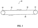
- a bulk material conveyor belt system is shown schematically in Figure 1 .
- the bulk material conveyor belt system 20 comprises a belt 22 that is driven about rollers 24 and forms a continuous loop.
- the upper portion of the continuous loop is referred to herein as the transfer run 26 and the lower portion of the continuous loop is referred to herein as the return run 28.
- the belt 22 has a trough-like shape (not shown) as it passes along the transfer run 26, but may also be flat.
- the belt may also have a flat or inverted trough-like shape along the return run 28.
- Figures 2 and 3 depict a skirt 30 and wear liner 32 assembly.
- Figure 3 depicts a cross-section of the settling region of the loading zone of a conveyor belt system 34.
- a skirt 30 is positioned on each opposite side of the center plane near each of the edges of the belt 22.
- Each skirt 30 extends downward and preferably has a lower edge 36 that is positioned above the belt 22 by an amount that is greater than the anticipated height of the bulk material 38 at that location. This prevents the bulk material 38 from abrading the skirts 30.
- the conveyor belt system 34 may also comprise a cover 40 connecting the top of the skirts 30 to prevent dust from escaping.
- the skirts 30 are preferably formed steel and may be supported by the frame (not shown) of the conveyor belt system 34, which also supports the components that support the belt 22.
- brackets 42 are preferably welded along the outer surface 44 of each skirt 30 adjacent the lower edge 36 of the skirt. Each bracket 42 protrudes from the outer surface 44 of the skirt 30 and comprises a vertically oriented through hole 46. Additionally, a plurality of threaded studs 48 protrude outward from the outer surface 44 of the skirt 30.
- the wear liner 32 may be formed of any material. Common materials include, abrasion resistant steel, steel faced with rubber, polyurethane, or ceramic tiles; weld deposited hard facing, cast basalt cement or cast molybdenum alloy segments. As shown in Figure 2 , each wear liner 32 preferably comprises a plurality of protruding bosses 50 adjacent the upper edge 52 of the wear liner and adjacent each of the opposite ends 54 of the wear liner, each of which comprises a vertically oriented threaded hole 56. Each wear liner 32 also preferably comprises a plurality of elongate openings 58 adjacent the upper edge 52 and between the bosses 50. The lower edge 60 of the wear liner is preferably parallel to the upper edge 52.
- the conveyor belt system 34 also preferably comprises a plurality of seals 64 and sealing clamps 66.
- the seals 64 may be made of rubber, polyurethane or other similar materials.
- Each seal 64 is generally rectangular and comprises a beveled lower edge 68.
- Each seal 64 also preferably comprises elongate openings (not shown) adjacent its upper edge 70, which are similar to those of the wear liners 32.
- the seal clamps 66 are preferably formed of steel strip and have a cross-section as shown in Figure 3 .
- Each seal clamp 66 comprises at least one through hole (not shown). The seal clamps are typically joined near the belt with an angle iron in a manner forming a substantially continuous clamping lip.
- the above-described components are preferably assembled by first placing the wear liner 32 against the outer surface 44 of the skirt 30 with the studs 48 of the skirt extending through the openings 58 of the wear liner.
- a threaded bolt or screw 72 is then inserted through the through hole 46 of one of the brackets 42 of the skirt 30 and is threadably engaged with the threaded hole 56 of one of the bosses 50 of the wear liner 32.
- Another threaded bolt or screw 72 is also inserted through the through hole 46 of one of the brackets 42 of the skirt 30 and is threadably engaged with the threaded hole 56 of another one of the bosses 50 of the wear liner 32.
- these threaded fasteners 72 are not to clamp the wear liner 32 to the skirt 30, but rather is to suspend the wear liner above the belt 22 from the skirt.
- the opposite ends 54 of the wear liner 32 can be independently raised and lowered relative to the belt 22. This is done to achieve a desired clearance between the wear liner 32 and the belt 22 along the lower edge 60 of the wear liner.
- the seal 64 is positioned against the wear liner 32, with the wear liner between the seal and the skirt 30 and the beveled lower edge 68 of the seal in contact with the belt 22.
- a nut and washer 74 can then be threadably attached to each of the studs 48 passing through the wear liner 32 and tightened against the seal 66 to clamp the seal against the wear liner and to clamp the wear liner against the skirt 30.
- the nuts and washers 74 can be threadably attached to the studs 48 prior to placing the seal 64 against the wear liner 32, where they can directly clamp the wear liner against the skirt 30, provided the openings of the seal are larger than the nuts and washers or the upper edge of the seal lies beneath the studs. Either way, with the seal 66 in place, each seal clamp 66 is then positioned such that the studs 48 extend through their respective through hole(s). It should be appreciated that not all studs 48 necessarily pass through a seal clamp 66.
- Another set of nuts and washers 76 can then be threadably attached to the respective studs 48 to thereby clamp the sealing clamps 66 against the seal 64, and thus the seal against the wear liner 32. Additionally it is common practice to tack weld liners in place to prevent accidental falling of the liner into the belt. If the elongate slots are closed and of proper dimensions the wear liner of this invention cannot fall far enough to contact the belt. If tack welding is desired it can be done from the outside of the enclosed skirt in contrast to conventional constructions. Additionally it is common practice to install wear liners in a self relieving fashion so that the distance of the wear liner from the belt increases uniformly but slightly in the direction of belt travel to prevent materials from being trapped between the belt and the wear liner and the belt. Such a self relieving pattern is much easier to accomplish with the current invention. After completing this, the conveyor belt system 34 can be operated.
- wear liners 32 When wear liners 32 become worn to the point of needing replacement, the above-described procedures can be reversed to remove each worn wear liner. Replacement wear liners 32 can then be attached by repeating the above-described procedures. Additionally, if the gaps between the lower edges 60 of the wear liners 32 and the belt 22 become larger than desired, due for example to wear or thermal expansion, the nuts 74 clamping the wear liner against the skirt can be loosened and the threaded fasteners 72 can be used as described above to adjust the gaps, after which the nuts can be retightened.
- the wear liners are uniformly dimensioned so that their position can be interchanged with each other to even out the wearing and prolong the useful life of the wear liners
- the wear liners can be repositioned or replace without requiring a person to climb onto the belt or otherwise access the inner surface of the skirt.
- the present invention does not complicate the structure of the skirts. It should be appreciated however that the present invention can still incorporate additional wear liners (such as indicated by the reference numeral 78 in Figure 3 ) that are attached to the inner surface of the skirts.
Landscapes
- Engineering & Computer Science (AREA)
- Mechanical Engineering (AREA)
- Framework For Endless Conveyors (AREA)
- Structure Of Belt Conveyors (AREA)
- Belt Conveyors (AREA)
Claims (9)
- Schüttgut-Förderbandsystem, umfassend:ein Band (22), wobei das Band eine Endlosschleife mit einer oberen Überführungsstrecke und einer unteren Rücklaufstrecke bildet, wobei das Band eine vertikal ausgerichtete mittige Ebene definiert, um die herum das Band allgemein symmetrisch ist,eine Randleiste (30), wobei die Randleiste eine untere Kante aufweist, die sich oberhalb der Überführungsstrecke erstreckt,eine Verschleißschutzverkleidung (32), wobei die Verschleißschutzverkleidung derart abnehmbar an der Randleiste angebracht ist, dass die Randleiste zwischen der Verschleißschutzverkleidung und der mittigen Ebene liegt, wobei die Verschleißschutzverkleidung eine untere Kante (60) aufweist, die sich oberhalb der Überführungsstrecke und unterhalb der unteren Kante der Randleiste erstreckt,eine Abdichtung (64), wobei die Abdichtung gegen die Verschleißschutzverkleidung geklemmt ist, wobei sich die Verschleißschutzverkleidung zwischen der Abdichtung und der Randleiste erstreckt,dadurch gekennzeichnet, dass es mindestens zwei mit Gewinde versehene Befestigungsmittel (72) umfasst, die die Verschleißschutzverkleidung derart abnehmbar an der Randleiste anbringen, dass die untere Kante der Verschleißschutzverkleidung im Verhältnis zum Band durch Drehung der Befestigungsmittel angehoben oder abgesenkt werden kann.
- Schüttgut-Förderbandsystem nach Anspruch 1, wobei die untere Kante (60) der Verschleißschutzverkleidung (32) gegenüberliegende Stirnränder (54) aufweist und die Stirnränder im Verhältnis zueinander durch Drehung der Befestigungsmittel (72) angehoben oder abgesenkt werden können.
- Schüttgut-Förderbandsystem nach Anspruch 1, wobei die Verschleißschutzverkleidung (32) mehrere längliche Öffnungen (58) umfasst, die Randleiste (30) mehrere Gewindebolzen (48) umfasst, sich die Bolzen durch die länglichen Öffnungen der Verschleißschutzverkleidung erstrecken, das Schüttgut-Förderbandsystem mehrere Gewindemuttern (74) umfasst und die Muttern über das Gewinde derart an den Bolzen angebracht sind, dass die Verschleißschutzverkleidung gegen die Randleiste geklemmt ist.
- Schüttgut-Förderbandsystem nach Anspruch 3, wobei die Muttern (74) erste Muttern (74) bilden, das Schüttgut-Förderbandsystem mindestens eine Abdichtungsklammer (66) und mindestens eine zweite Gewindemutter (76) umfasst, die zweite Mutter (76) über das Gewinde derart an einem der Bolzen (48) angebracht ist, dass die Abdichtungsklammer gegen die Abdichtung (64) geklemmt ist, und die Abdichtung durch die Abdichtungsklammer zumindest teilweise gegen die Randleiste (30) geklemmt ist.
- Schüttgut-Förderbandsystem nach Anspruch 4, wobei die Abdichtung (64) durch die ersten Muttern (74) zumindest teilweise auch gegen die Randleiste (30) geklemmt ist.
- Verfahren zum Austauschen einer Verschleißschutzverkleidung (32), umfassend:Zugreifen auf ein Schüttgut-Förderbandsystem, wobei das Schüttgut-Förderbandsystem ein Band (22), eine Randleiste (30) und eine verschlissene Verschleißschutzverkleidung (32) umfasst, wobei das Band eine Endlosschleife mit einer oberen Überführungsstrecke (26) und einer unteren Rücklaufstrecke (28) bildet, wobei das Band eine vertikal ausgerichtete mittige Ebene definiert, um die herum das Band allgemein symmetrisch ist, wobei die Randleiste eine untere Kante (36) aufweist, die sich oberhalb der Überführungsstrecke erstreckt, wobei die verschlissene Verschleißschutzverkleidung derart abnehmbar an der Randleiste angebracht ist, dass die Randleiste zwischen der verschlissenen Verschleißschutzverkleidung und der mittigen Ebene liegt, wobei die verschlissene Verschleißschutzverkleidung eine untere Kante (60) aufweist, die sich oberhalb der Überführungsstrecke und unterhalb der unteren Kante der Randleiste erstreckt,Entfernen der verschlissenen Verschleißschutzverkleidung vom Schüttgut-Förderbandsystem, wobei das Entfernen von einer Person ausgeführt wird, während die Randleiste zwischen der Person und der mittigen Ebene liegt,Anbringen einer Ersatz-Verschleißschutzverkleidung am Schüttgut-Förderbandsystem über mindestens zwei mit Gewinde versehene Befestigungsmittel (72), wobei die Ersatz-Verschleißschutzverkleidung eine untere Kante aufweist, wobei das Anbringen von einer Person ausgeführt wird, während die Randleiste zwischen der Person und der mittigen Ebene liegt, und derart, dass sich die untere Kante der Ersatz-Verschleißschutzverkleidung oberhalb der Überführungsstrecke und unterhalb der unteren Kante der Randleiste erstreckt,dadurch gekennzeichnet, dass
das Anbringen außerdem das Bewegen der unteren Kante der Ersatz-Verschleißschutzverkleidung im Verhältnis zum Band durch Drehen der Befestigungsmittel umfasst, und
Anbringen einer Abdichtung (64) an dem Schüttgut-Förderbandsystem derart, dass die Abdichtung gegen die Ersatz-Verschleißschutzverkleidung geklemmt wird und sich die Ersatz-Verschleißschutzverkleidung zwischen der Abdichtung und der Randleiste erstreckt. - Verfahren nach Anspruch 6, wobei der Schritt des Bewegens der unteren Kante (36) der Ersatz-Verschleißschutzverkleidung (32) von einer Person ausgeführt wird, während die Randleiste (30) zwischen der Person und der mittigen Ebene liegt.
- Verfahren nach Anspruch 7, wobei die Person, die den Schritt des Entfernens der verschlissenen Verschleißschutzverkleidung (32) von dem Schüttgut-Förderbandsystem ausführt, auch die Person ist, die den Schritt des Anbringens der Ersatz-Verschleißschutzverkleidung an dem Schüttgut-Förderbandsystem ausführt, und auch die Person ist, die den Schritt des Anbringens einer Abdichtung (64) am Förderbandsystem ausführt, und auch die Person ist, die den Schritt des Bewegens der unteren Kante (36) der Ersatz-Verschleißschutzverkleidung ausführt.
- Verfahren nach Anspruch 6, wobei die Ersatz-Verschleißschutzverkleidung (32) mehrere längliche Öffnungen (58) umfasst und die Randleiste (30) mehrere Gewindebolzen (48) umfasst und der Schritt des Anbringens der Ersatz-Verschleißschutzverkleidung am Schüttgut-Förderbandsystem das Hindurchstecken der Bolzen durch die länglichen Öffnungen der Ersatz-Verschleißschutzverkleidung und das Verwenden mehrerer Muttern (74) zum Klemmen der Verschleißschutzverkleidung gegen die Randleiste über das Gewinde durch Anbringen der Muttern an den Bolzen über das Gewinde umfasst.
Applications Claiming Priority (2)
| Application Number | Priority Date | Filing Date | Title |
|---|---|---|---|
| US12/234,384 US8006830B2 (en) | 2008-09-19 | 2008-09-19 | Exteriorly mounted wear liner for bulk material conveyor belt systems |
| PCT/US2009/057409 WO2010033760A1 (en) | 2008-09-19 | 2009-09-18 | Exteriorly mounted wear liner for bulk material conveyor belt systems |
Publications (3)
| Publication Number | Publication Date |
|---|---|
| EP2323929A1 EP2323929A1 (de) | 2011-05-25 |
| EP2323929A4 EP2323929A4 (de) | 2015-08-05 |
| EP2323929B1 true EP2323929B1 (de) | 2016-03-16 |
Family
ID=42036507
Family Applications (1)
| Application Number | Title | Priority Date | Filing Date |
|---|---|---|---|
| EP09815235.8A Active EP2323929B1 (de) | 2008-09-19 | 2009-09-18 | Extern montierte verschleissschutzverkleidung für schüttgut-förderbandsysteme |
Country Status (15)
| Country | Link |
|---|---|
| US (1) | US8006830B2 (de) |
| EP (1) | EP2323929B1 (de) |
| CN (1) | CN102131720B (de) |
| AR (1) | AR073611A1 (de) |
| AU (1) | AU2009293167B2 (de) |
| BR (1) | BRPI0918630B1 (de) |
| CA (1) | CA2730099C (de) |
| CL (1) | CL2011000580A1 (de) |
| ES (1) | ES2572827T3 (de) |
| MX (1) | MX2011003017A (de) |
| PE (1) | PE20110882A1 (de) |
| PL (1) | PL2323929T3 (de) |
| TW (1) | TWI501911B (de) |
| WO (1) | WO2010033760A1 (de) |
| ZA (1) | ZA201100440B (de) |
Families Citing this family (14)
| Publication number | Priority date | Publication date | Assignee | Title |
|---|---|---|---|---|
| WO2010033898A1 (en) * | 2008-09-22 | 2010-03-25 | Martin Engineering Company | Dual apron seal |
| US20110085883A1 (en) * | 2009-10-09 | 2011-04-14 | Martin Engineering Company | Adjustable wear and diversion device for bulk material transfer systems and method of using the same |
| CN102689767A (zh) * | 2012-06-06 | 2012-09-26 | 山西长治王庄煤业有限责任公司 | 一种挡煤装置 |
| WO2014031188A1 (en) | 2012-08-22 | 2014-02-27 | Benetech, Inc. | Externally adjustable internal wearliner for a material conveyor system |
| US9174802B2 (en) * | 2013-12-20 | 2015-11-03 | Richwood Industries | Bulk materials transfer chute lining |
| PL3192755T3 (pl) * | 2016-01-18 | 2020-02-28 | Joseph Vögele AG | Urządzenie przenośnikowe z ogranicznikiem przenoszonego strumienia |
| CN105947548A (zh) * | 2016-07-11 | 2016-09-21 | 江苏工力重机有限公司 | 一种皮带机头部挡料板装置 |
| AU2018326292B2 (en) * | 2017-08-28 | 2023-10-12 | CPC Engineering Pty Ltd | Skirt system for a conveyor |
| CA3073968A1 (en) * | 2017-08-28 | 2019-03-07 | CPC Engineering Pty Ltd | Conveyor skirt system |
| WO2020058834A1 (en) * | 2018-09-18 | 2020-03-26 | Luca Toncelli | Method and plant for manufacturing articles made of composite stone material and device for distributing a mix for such manufacturing |
| CA3046751A1 (en) | 2019-06-17 | 2020-12-17 | Lyndon Graff | Belt conveyor capable of conveying oilseed products |
| US12214309B2 (en) | 2021-04-06 | 2025-02-04 | Benetech, Inc. | Passive dust filter for an inspection hatch |
| US11919719B2 (en) | 2021-05-13 | 2024-03-05 | Benetech, Inc. | Drop and slide out idler assembly |
| CN114873162A (zh) * | 2022-05-27 | 2022-08-09 | 沈阳金鼎电科环境工程有限公司 | 一种自动升降导料槽装置 |
Family Cites Families (27)
| Publication number | Priority date | Publication date | Assignee | Title |
|---|---|---|---|---|
| US3024893A (en) * | 1959-12-18 | 1962-03-13 | Max S Lambert | Skirtboard and sealer for conveyor systems |
| GB933810A (en) | 1962-04-05 | 1963-08-14 | Wharton Engs Elstree Ltd | Moving band, belt or the like conveyors |
| US3651910A (en) * | 1969-01-28 | 1972-03-28 | Dale Corp Van | Adjustable discharge means |
| DE2418458B2 (de) | 1974-04-17 | 1980-04-17 | Fried. Krupp Gmbh, 4300 Essen | Vorrichtung zum Befestigen von Abdichtleisten an der Materialführung dienenden Führungsblechen eines Förderbandes |
| US4204595A (en) * | 1978-11-16 | 1980-05-27 | Amax Inc. | Adjustable conveyor belt skirtboard |
| US4896435A (en) * | 1988-05-10 | 1990-01-30 | Gala Industries Inc. | Replaceable wear parts for centrifugal pellet dryers |
| US5016747A (en) | 1988-08-01 | 1991-05-21 | Martin Engineering Company | Barrier seal for conveyor skirtboard |
| US5184706A (en) * | 1990-01-26 | 1993-02-09 | Mcneilus Truck & Manufacturing, Inc. | Polymeric composite discharge chutes for concrete having a wear resistant liner |
| US5048669A (en) * | 1990-03-13 | 1991-09-17 | Martin Engineering Company | Modular conveyor belt sealing system |
| JPH05319535A (ja) * | 1991-10-10 | 1993-12-03 | Mass Flow Equipment Bv | ベルトコンベアの搭載槽用シーリングエプロン装置 |
| US5350053A (en) * | 1991-11-22 | 1994-09-27 | Arch Environmental Equipment, Inc. | Belt conveyor input station |
| US5244069A (en) * | 1992-09-10 | 1993-09-14 | Cosgrove James H | Apparatus for protecting mixer truck chute against wear |
| ZA939109B (en) * | 1992-11-04 | 1994-08-22 | Brelko Patents Pty Ltd | Belt conveyor skirt seal arrangement |
| JPH0820419A (ja) * | 1994-07-07 | 1996-01-23 | Tokushu Denkyoku Kk | ベルトコンベアにおける荷受部設置用スカート及び荷こぼれ等の防止装置 |
| JP3389729B2 (ja) | 1995-03-22 | 2003-03-24 | 石川島播磨重工業株式会社 | ベルトコンベヤのスカート構造 |
| DE29718196U1 (de) * | 1997-10-14 | 1998-02-12 | Stahlgruber Otto Gruber GmbH & Co, 81675 München | Abdichtvorrichtung für Stetigförderer |
| US6041906A (en) * | 1998-02-13 | 2000-03-28 | Arch Environmental Equipment Inc. | Conveyor chute liner |
| JP2000072220A (ja) | 1998-08-28 | 2000-03-07 | Babcock Hitachi Kk | ベルトコンベアの粒塊物落下防止装置 |
| US6279715B1 (en) * | 1999-03-19 | 2001-08-28 | Harold L. Herren | Chute liner system |
| JP2001233432A (ja) * | 2000-02-24 | 2001-08-28 | Ishikawajima Harima Heavy Ind Co Ltd | ベルトコンベヤのスカート部構造 |
| US6547062B2 (en) * | 2001-05-08 | 2003-04-15 | Argonics, Inc. | Clamping system for a sealing element on a conveyor system, and a method of maintaining a sealing element on a conveyor system |
| US6763935B2 (en) * | 2002-08-16 | 2004-07-20 | Nelson Williams Linings, Inc. | Pivotable conveyor skirt board assembly |
| US20040182673A1 (en) * | 2003-01-29 | 2004-09-23 | Baller Werner Josef | Transfer chute and method of operating the chute |
| US6684999B1 (en) * | 2003-05-05 | 2004-02-03 | Arch Environmental Equipment, Inc. | Impact liner for granular material |
| ZA200804004B (en) | 2005-11-11 | 2009-10-28 | Wear Applic & Man Services Pty | Liner plate replacement |
| US7938244B2 (en) * | 2006-05-11 | 2011-05-10 | Trelleborg Queensland Rubber Pty. Ltd. | Flexible liner for hoppers or chutes |
| US7588134B2 (en) * | 2007-07-19 | 2009-09-15 | Alcan International Limited | Deformable/inflatable wear liner |
-
2008
- 2008-09-19 US US12/234,384 patent/US8006830B2/en active Active
-
2009
- 2009-09-18 CN CN200980132485.7A patent/CN102131720B/zh not_active Expired - Fee Related
- 2009-09-18 PE PE2011000611A patent/PE20110882A1/es active IP Right Grant
- 2009-09-18 EP EP09815235.8A patent/EP2323929B1/de active Active
- 2009-09-18 ES ES09815235.8T patent/ES2572827T3/es active Active
- 2009-09-18 AR ARP090103596A patent/AR073611A1/es not_active Application Discontinuation
- 2009-09-18 WO PCT/US2009/057409 patent/WO2010033760A1/en not_active Ceased
- 2009-09-18 MX MX2011003017A patent/MX2011003017A/es active IP Right Grant
- 2009-09-18 CA CA2730099A patent/CA2730099C/en not_active Expired - Fee Related
- 2009-09-18 TW TW098131677A patent/TWI501911B/zh not_active IP Right Cessation
- 2009-09-18 BR BRPI0918630-1A patent/BRPI0918630B1/pt not_active IP Right Cessation
- 2009-09-18 AU AU2009293167A patent/AU2009293167B2/en not_active Ceased
- 2009-09-18 PL PL09815235.8T patent/PL2323929T3/pl unknown
-
2011
- 2011-01-17 ZA ZA2011/00440A patent/ZA201100440B/en unknown
- 2011-03-18 CL CL2011000580A patent/CL2011000580A1/es unknown
Also Published As
| Publication number | Publication date |
|---|---|
| CA2730099C (en) | 2015-07-14 |
| CA2730099A1 (en) | 2010-03-25 |
| CN102131720A (zh) | 2011-07-20 |
| PL2323929T3 (pl) | 2016-09-30 |
| MX2011003017A (es) | 2011-04-21 |
| AU2009293167B2 (en) | 2015-02-19 |
| EP2323929A4 (de) | 2015-08-05 |
| ZA201100440B (en) | 2011-10-26 |
| WO2010033760A1 (en) | 2010-03-25 |
| AU2009293167A1 (en) | 2010-03-25 |
| ES2572827T3 (es) | 2016-06-02 |
| TWI501911B (zh) | 2015-10-01 |
| BRPI0918630B1 (pt) | 2019-03-19 |
| BRPI0918630A2 (pt) | 2015-12-01 |
| US8006830B2 (en) | 2011-08-30 |
| PE20110882A1 (es) | 2011-12-19 |
| US20100072034A1 (en) | 2010-03-25 |
| EP2323929A1 (de) | 2011-05-25 |
| CL2011000580A1 (es) | 2011-08-26 |
| AR073611A1 (es) | 2010-11-17 |
| CN102131720B (zh) | 2015-04-22 |
| TW201020188A (en) | 2010-06-01 |
Similar Documents
| Publication | Publication Date | Title |
|---|---|---|
| EP2323929B1 (de) | Extern montierte verschleissschutzverkleidung für schüttgut-förderbandsysteme | |
| US6763935B2 (en) | Pivotable conveyor skirt board assembly | |
| CA2958051C (en) | Wear surface | |
| AU2007203137A1 (en) | Impact bed for conveyor systems | |
| US8851543B2 (en) | Reversible lifting lug | |
| AU2019236704B2 (en) | Conveyor skirt liner system | |
| CA2716177C (en) | Clamping arrangement for a conveyor seal | |
| CA2446066C (en) | Pivotable conveyor skirt board assembly | |
| CN223697982U (zh) | 一种分级破碎机侧板 | |
| CA2841670A1 (en) | Reversible lifting lug | |
| JPH0820419A (ja) | ベルトコンベアにおける荷受部設置用スカート及び荷こぼれ等の防止装置 | |
| CN209306245U (zh) | 一种可快速安装更换的耐磨衬板结构 | |
| MXPA03010906A (es) | Montaje de tablero de faldon de transportador articulable. | |
| KR19980015038U (ko) | 콘베어용 스커트 지지장치 | |
| AU2013205449A1 (en) | Skirt liner safety retention system |
Legal Events
| Date | Code | Title | Description |
|---|---|---|---|
| PUAI | Public reference made under article 153(3) epc to a published international application that has entered the european phase |
Free format text: ORIGINAL CODE: 0009012 |
|
| 17P | Request for examination filed |
Effective date: 20110215 |
|
| AK | Designated contracting states |
Kind code of ref document: A1 Designated state(s): AT BE BG CH CY CZ DE DK EE ES FI FR GB GR HR HU IE IS IT LI LT LU LV MC MK MT NL NO PL PT RO SE SI SK SM TR |
|
| AX | Request for extension of the european patent |
Extension state: AL BA RS |
|
| DAX | Request for extension of the european patent (deleted) | ||
| RA4 | Supplementary search report drawn up and despatched (corrected) |
Effective date: 20150708 |
|
| RIC1 | Information provided on ipc code assigned before grant |
Ipc: B65G 21/20 20060101AFI20150702BHEP |
|
| GRAP | Despatch of communication of intention to grant a patent |
Free format text: ORIGINAL CODE: EPIDOSNIGR1 |
|
| INTG | Intention to grant announced |
Effective date: 20151104 |
|
| GRAS | Grant fee paid |
Free format text: ORIGINAL CODE: EPIDOSNIGR3 |
|
| GRAA | (expected) grant |
Free format text: ORIGINAL CODE: 0009210 |
|
| AK | Designated contracting states |
Kind code of ref document: B1 Designated state(s): AT BE BG CH CY CZ DE DK EE ES FI FR GB GR HR HU IE IS IT LI LT LU LV MC MK MT NL NO PL PT RO SE SI SK SM TR |
|
| REG | Reference to a national code |
Ref country code: GB Ref legal event code: FG4D |
|
| REG | Reference to a national code |
Ref country code: CH Ref legal event code: EP |
|
| REG | Reference to a national code |
Ref country code: IE Ref legal event code: FG4D |
|
| REG | Reference to a national code |
Ref country code: AT Ref legal event code: REF Ref document number: 781013 Country of ref document: AT Kind code of ref document: T Effective date: 20160415 |
|
| REG | Reference to a national code |
Ref country code: DE Ref legal event code: R096 Ref document number: 602009036874 Country of ref document: DE |
|
| REG | Reference to a national code |
Ref country code: ES Ref legal event code: FG2A Ref document number: 2572827 Country of ref document: ES Kind code of ref document: T3 Effective date: 20160602 |
|
| REG | Reference to a national code |
Ref country code: NL Ref legal event code: MP Effective date: 20160316 |
|
| REG | Reference to a national code |
Ref country code: LT Ref legal event code: MG4D |
|
| PG25 | Lapsed in a contracting state [announced via postgrant information from national office to epo] |
Ref country code: HR Free format text: LAPSE BECAUSE OF FAILURE TO SUBMIT A TRANSLATION OF THE DESCRIPTION OR TO PAY THE FEE WITHIN THE PRESCRIBED TIME-LIMIT Effective date: 20160316 Ref country code: FI Free format text: LAPSE BECAUSE OF FAILURE TO SUBMIT A TRANSLATION OF THE DESCRIPTION OR TO PAY THE FEE WITHIN THE PRESCRIBED TIME-LIMIT Effective date: 20160316 Ref country code: NO Free format text: LAPSE BECAUSE OF FAILURE TO SUBMIT A TRANSLATION OF THE DESCRIPTION OR TO PAY THE FEE WITHIN THE PRESCRIBED TIME-LIMIT Effective date: 20160616 Ref country code: GR Free format text: LAPSE BECAUSE OF FAILURE TO SUBMIT A TRANSLATION OF THE DESCRIPTION OR TO PAY THE FEE WITHIN THE PRESCRIBED TIME-LIMIT Effective date: 20160617 |
|
| REG | Reference to a national code |
Ref country code: AT Ref legal event code: MK05 Ref document number: 781013 Country of ref document: AT Kind code of ref document: T Effective date: 20160316 |
|
| PG25 | Lapsed in a contracting state [announced via postgrant information from national office to epo] |
Ref country code: NL Free format text: LAPSE BECAUSE OF FAILURE TO SUBMIT A TRANSLATION OF THE DESCRIPTION OR TO PAY THE FEE WITHIN THE PRESCRIBED TIME-LIMIT Effective date: 20160316 Ref country code: LT Free format text: LAPSE BECAUSE OF FAILURE TO SUBMIT A TRANSLATION OF THE DESCRIPTION OR TO PAY THE FEE WITHIN THE PRESCRIBED TIME-LIMIT Effective date: 20160316 Ref country code: LV Free format text: LAPSE BECAUSE OF FAILURE TO SUBMIT A TRANSLATION OF THE DESCRIPTION OR TO PAY THE FEE WITHIN THE PRESCRIBED TIME-LIMIT Effective date: 20160316 Ref country code: SE Free format text: LAPSE BECAUSE OF FAILURE TO SUBMIT A TRANSLATION OF THE DESCRIPTION OR TO PAY THE FEE WITHIN THE PRESCRIBED TIME-LIMIT Effective date: 20160316 |
|
| REG | Reference to a national code |
Ref country code: FR Ref legal event code: PLFP Year of fee payment: 8 |
|
| PG25 | Lapsed in a contracting state [announced via postgrant information from national office to epo] |
Ref country code: EE Free format text: LAPSE BECAUSE OF FAILURE TO SUBMIT A TRANSLATION OF THE DESCRIPTION OR TO PAY THE FEE WITHIN THE PRESCRIBED TIME-LIMIT Effective date: 20160316 Ref country code: IS Free format text: LAPSE BECAUSE OF FAILURE TO SUBMIT A TRANSLATION OF THE DESCRIPTION OR TO PAY THE FEE WITHIN THE PRESCRIBED TIME-LIMIT Effective date: 20160716 |
|
| PG25 | Lapsed in a contracting state [announced via postgrant information from national office to epo] |
Ref country code: RO Free format text: LAPSE BECAUSE OF FAILURE TO SUBMIT A TRANSLATION OF THE DESCRIPTION OR TO PAY THE FEE WITHIN THE PRESCRIBED TIME-LIMIT Effective date: 20160316 Ref country code: SK Free format text: LAPSE BECAUSE OF FAILURE TO SUBMIT A TRANSLATION OF THE DESCRIPTION OR TO PAY THE FEE WITHIN THE PRESCRIBED TIME-LIMIT Effective date: 20160316 Ref country code: CZ Free format text: LAPSE BECAUSE OF FAILURE TO SUBMIT A TRANSLATION OF THE DESCRIPTION OR TO PAY THE FEE WITHIN THE PRESCRIBED TIME-LIMIT Effective date: 20160316 Ref country code: SM Free format text: LAPSE BECAUSE OF FAILURE TO SUBMIT A TRANSLATION OF THE DESCRIPTION OR TO PAY THE FEE WITHIN THE PRESCRIBED TIME-LIMIT Effective date: 20160316 Ref country code: PT Free format text: LAPSE BECAUSE OF FAILURE TO SUBMIT A TRANSLATION OF THE DESCRIPTION OR TO PAY THE FEE WITHIN THE PRESCRIBED TIME-LIMIT Effective date: 20160718 Ref country code: AT Free format text: LAPSE BECAUSE OF FAILURE TO SUBMIT A TRANSLATION OF THE DESCRIPTION OR TO PAY THE FEE WITHIN THE PRESCRIBED TIME-LIMIT Effective date: 20160316 |
|
| REG | Reference to a national code |
Ref country code: DE Ref legal event code: R097 Ref document number: 602009036874 Country of ref document: DE |
|
| PG25 | Lapsed in a contracting state [announced via postgrant information from national office to epo] |
Ref country code: BE Free format text: LAPSE BECAUSE OF FAILURE TO SUBMIT A TRANSLATION OF THE DESCRIPTION OR TO PAY THE FEE WITHIN THE PRESCRIBED TIME-LIMIT Effective date: 20160316 |
|
| PLBE | No opposition filed within time limit |
Free format text: ORIGINAL CODE: 0009261 |
|
| STAA | Information on the status of an ep patent application or granted ep patent |
Free format text: STATUS: NO OPPOSITION FILED WITHIN TIME LIMIT |
|
| PG25 | Lapsed in a contracting state [announced via postgrant information from national office to epo] |
Ref country code: DK Free format text: LAPSE BECAUSE OF FAILURE TO SUBMIT A TRANSLATION OF THE DESCRIPTION OR TO PAY THE FEE WITHIN THE PRESCRIBED TIME-LIMIT Effective date: 20160316 |
|
| 26N | No opposition filed |
Effective date: 20161219 |
|
| PG25 | Lapsed in a contracting state [announced via postgrant information from national office to epo] |
Ref country code: BG Free format text: LAPSE BECAUSE OF FAILURE TO SUBMIT A TRANSLATION OF THE DESCRIPTION OR TO PAY THE FEE WITHIN THE PRESCRIBED TIME-LIMIT Effective date: 20160616 |
|
| PG25 | Lapsed in a contracting state [announced via postgrant information from national office to epo] |
Ref country code: MC Free format text: LAPSE BECAUSE OF FAILURE TO SUBMIT A TRANSLATION OF THE DESCRIPTION OR TO PAY THE FEE WITHIN THE PRESCRIBED TIME-LIMIT Effective date: 20160316 |
|
| REG | Reference to a national code |
Ref country code: CH Ref legal event code: PL |
|
| PG25 | Lapsed in a contracting state [announced via postgrant information from national office to epo] |
Ref country code: SI Free format text: LAPSE BECAUSE OF FAILURE TO SUBMIT A TRANSLATION OF THE DESCRIPTION OR TO PAY THE FEE WITHIN THE PRESCRIBED TIME-LIMIT Effective date: 20160316 |
|
| PG25 | Lapsed in a contracting state [announced via postgrant information from national office to epo] |
Ref country code: LI Free format text: LAPSE BECAUSE OF NON-PAYMENT OF DUE FEES Effective date: 20160930 Ref country code: CH Free format text: LAPSE BECAUSE OF NON-PAYMENT OF DUE FEES Effective date: 20160930 |
|
| REG | Reference to a national code |
Ref country code: FR Ref legal event code: PLFP Year of fee payment: 9 |
|
| PG25 | Lapsed in a contracting state [announced via postgrant information from national office to epo] |
Ref country code: LU Free format text: LAPSE BECAUSE OF NON-PAYMENT OF DUE FEES Effective date: 20160918 |
|
| PG25 | Lapsed in a contracting state [announced via postgrant information from national office to epo] |
Ref country code: CY Free format text: LAPSE BECAUSE OF FAILURE TO SUBMIT A TRANSLATION OF THE DESCRIPTION OR TO PAY THE FEE WITHIN THE PRESCRIBED TIME-LIMIT Effective date: 20160316 Ref country code: HU Free format text: LAPSE BECAUSE OF FAILURE TO SUBMIT A TRANSLATION OF THE DESCRIPTION OR TO PAY THE FEE WITHIN THE PRESCRIBED TIME-LIMIT; INVALID AB INITIO Effective date: 20090918 |
|
| PG25 | Lapsed in a contracting state [announced via postgrant information from national office to epo] |
Ref country code: MK Free format text: LAPSE BECAUSE OF FAILURE TO SUBMIT A TRANSLATION OF THE DESCRIPTION OR TO PAY THE FEE WITHIN THE PRESCRIBED TIME-LIMIT Effective date: 20160316 Ref country code: MT Free format text: LAPSE BECAUSE OF NON-PAYMENT OF DUE FEES Effective date: 20160930 |
|
| REG | Reference to a national code |
Ref country code: FR Ref legal event code: PLFP Year of fee payment: 10 |
|
| PGFP | Annual fee paid to national office [announced via postgrant information from national office to epo] |
Ref country code: GB Payment date: 20200819 Year of fee payment: 12 Ref country code: FR Payment date: 20200819 Year of fee payment: 12 Ref country code: IE Payment date: 20200821 Year of fee payment: 12 Ref country code: DE Payment date: 20200819 Year of fee payment: 12 Ref country code: TR Payment date: 20200824 Year of fee payment: 12 |
|
| PGFP | Annual fee paid to national office [announced via postgrant information from national office to epo] |
Ref country code: PL Payment date: 20200821 Year of fee payment: 12 Ref country code: IT Payment date: 20200824 Year of fee payment: 12 |
|
| PGFP | Annual fee paid to national office [announced via postgrant information from national office to epo] |
Ref country code: ES Payment date: 20201001 Year of fee payment: 12 |
|
| REG | Reference to a national code |
Ref country code: DE Ref legal event code: R119 Ref document number: 602009036874 Country of ref document: DE |
|
| GBPC | Gb: european patent ceased through non-payment of renewal fee |
Effective date: 20210918 |
|
| PG25 | Lapsed in a contracting state [announced via postgrant information from national office to epo] |
Ref country code: IE Free format text: LAPSE BECAUSE OF NON-PAYMENT OF DUE FEES Effective date: 20210918 Ref country code: GB Free format text: LAPSE BECAUSE OF NON-PAYMENT OF DUE FEES Effective date: 20210918 Ref country code: FR Free format text: LAPSE BECAUSE OF NON-PAYMENT OF DUE FEES Effective date: 20210930 Ref country code: DE Free format text: LAPSE BECAUSE OF NON-PAYMENT OF DUE FEES Effective date: 20220401 |
|
| PG25 | Lapsed in a contracting state [announced via postgrant information from national office to epo] |
Ref country code: IT Free format text: LAPSE BECAUSE OF NON-PAYMENT OF DUE FEES Effective date: 20210918 |
|
| REG | Reference to a national code |
Ref country code: ES Ref legal event code: FD2A Effective date: 20230202 |
|
| PG25 | Lapsed in a contracting state [announced via postgrant information from national office to epo] |
Ref country code: ES Free format text: LAPSE BECAUSE OF NON-PAYMENT OF DUE FEES Effective date: 20210919 |
|
| PG25 | Lapsed in a contracting state [announced via postgrant information from national office to epo] |
Ref country code: PL Free format text: LAPSE BECAUSE OF NON-PAYMENT OF DUE FEES Effective date: 20210918 |