EP2321983B1 - Verfahren zur implementierung von mesh-netzwerk-kommunikationen mithilfe eines mesh-netzwerk-protokolls - Google Patents
Verfahren zur implementierung von mesh-netzwerk-kommunikationen mithilfe eines mesh-netzwerk-protokolls Download PDFInfo
- Publication number
- EP2321983B1 EP2321983B1 EP09811849.0A EP09811849A EP2321983B1 EP 2321983 B1 EP2321983 B1 EP 2321983B1 EP 09811849 A EP09811849 A EP 09811849A EP 2321983 B1 EP2321983 B1 EP 2321983B1
- Authority
- EP
- European Patent Office
- Prior art keywords
- node
- route
- key
- frame
- bits
- Prior art date
- Legal status (The legal status is an assumption and is not a legal conclusion. Google has not performed a legal analysis and makes no representation as to the accuracy of the status listed.)
- Active
Links
Images


Classifications
-
- H—ELECTRICITY
- H04—ELECTRIC COMMUNICATION TECHNIQUE
- H04L—TRANSMISSION OF DIGITAL INFORMATION, e.g. TELEGRAPHIC COMMUNICATION
- H04L45/00—Routing or path finding of packets in data switching networks
- H04L45/34—Source routing
-
- H—ELECTRICITY
- H04—ELECTRIC COMMUNICATION TECHNIQUE
- H04L—TRANSMISSION OF DIGITAL INFORMATION, e.g. TELEGRAPHIC COMMUNICATION
- H04L45/00—Routing or path finding of packets in data switching networks
- H04L45/20—Hop count for routing purposes, e.g. TTL
-
- H—ELECTRICITY
- H04—ELECTRIC COMMUNICATION TECHNIQUE
- H04L—TRANSMISSION OF DIGITAL INFORMATION, e.g. TELEGRAPHIC COMMUNICATION
- H04L45/00—Routing or path finding of packets in data switching networks
- H04L45/42—Centralised routing
-
- H—ELECTRICITY
- H04—ELECTRIC COMMUNICATION TECHNIQUE
- H04L—TRANSMISSION OF DIGITAL INFORMATION, e.g. TELEGRAPHIC COMMUNICATION
- H04L45/00—Routing or path finding of packets in data switching networks
- H04L45/44—Distributed routing
-
- H—ELECTRICITY
- H04—ELECTRIC COMMUNICATION TECHNIQUE
- H04L—TRANSMISSION OF DIGITAL INFORMATION, e.g. TELEGRAPHIC COMMUNICATION
- H04L45/00—Routing or path finding of packets in data switching networks
- H04L45/48—Routing tree calculation
-
- H—ELECTRICITY
- H04—ELECTRIC COMMUNICATION TECHNIQUE
- H04L—TRANSMISSION OF DIGITAL INFORMATION, e.g. TELEGRAPHIC COMMUNICATION
- H04L45/00—Routing or path finding of packets in data switching networks
- H04L45/52—Multiprotocol routers
-
- H—ELECTRICITY
- H04—ELECTRIC COMMUNICATION TECHNIQUE
- H04L—TRANSMISSION OF DIGITAL INFORMATION, e.g. TELEGRAPHIC COMMUNICATION
- H04L45/00—Routing or path finding of packets in data switching networks
- H04L45/72—Routing based on the source address
-
- H—ELECTRICITY
- H04—ELECTRIC COMMUNICATION TECHNIQUE
- H04L—TRANSMISSION OF DIGITAL INFORMATION, e.g. TELEGRAPHIC COMMUNICATION
- H04L63/00—Network architectures or network communication protocols for network security
- H04L63/12—Applying verification of the received information
- H04L63/123—Applying verification of the received information received data contents, e.g. message integrity
-
- H—ELECTRICITY
- H04—ELECTRIC COMMUNICATION TECHNIQUE
- H04W—WIRELESS COMMUNICATION NETWORKS
- H04W40/00—Communication routing or communication path finding
- H04W40/005—Routing actions in the presence of nodes in sleep or doze mode
-
- H—ELECTRICITY
- H04—ELECTRIC COMMUNICATION TECHNIQUE
- H04W—WIRELESS COMMUNICATION NETWORKS
- H04W40/00—Communication routing or communication path finding
- H04W40/02—Communication route or path selection, e.g. power-based or shortest path routing
-
- H—ELECTRICITY
- H04—ELECTRIC COMMUNICATION TECHNIQUE
- H04W—WIRELESS COMMUNICATION NETWORKS
- H04W40/00—Communication routing or communication path finding
- H04W40/02—Communication route or path selection, e.g. power-based or shortest path routing
- H04W40/12—Communication route or path selection, e.g. power-based or shortest path routing based on transmission quality or channel quality
-
- H—ELECTRICITY
- H04—ELECTRIC COMMUNICATION TECHNIQUE
- H04W—WIRELESS COMMUNICATION NETWORKS
- H04W40/00—Communication routing or communication path finding
- H04W40/02—Communication route or path selection, e.g. power-based or shortest path routing
- H04W40/22—Communication route or path selection, e.g. power-based or shortest path routing using selective relaying for reaching a BTS [Base Transceiver Station] or an access point
-
- H—ELECTRICITY
- H04—ELECTRIC COMMUNICATION TECHNIQUE
- H04W—WIRELESS COMMUNICATION NETWORKS
- H04W40/00—Communication routing or communication path finding
- H04W40/24—Connectivity information management, e.g. connectivity discovery or connectivity update
- H04W40/246—Connectivity information discovery
-
- H—ELECTRICITY
- H04—ELECTRIC COMMUNICATION TECHNIQUE
- H04W—WIRELESS COMMUNICATION NETWORKS
- H04W40/00—Communication routing or communication path finding
- H04W40/24—Connectivity information management, e.g. connectivity discovery or connectivity update
- H04W40/28—Connectivity information management, e.g. connectivity discovery or connectivity update for reactive routing
-
- H—ELECTRICITY
- H04—ELECTRIC COMMUNICATION TECHNIQUE
- H04W—WIRELESS COMMUNICATION NETWORKS
- H04W48/00—Access restriction; Network selection; Access point selection
- H04W48/18—Selecting a network or a communication service
-
- H—ELECTRICITY
- H04—ELECTRIC COMMUNICATION TECHNIQUE
- H04W—WIRELESS COMMUNICATION NETWORKS
- H04W8/00—Network data management
- H04W8/02—Processing of mobility data, e.g. registration information at HLR [Home Location Register] or VLR [Visitor Location Register]; Transfer of mobility data, e.g. between HLR, VLR or external networks
-
- H—ELECTRICITY
- H04—ELECTRIC COMMUNICATION TECHNIQUE
- H04W—WIRELESS COMMUNICATION NETWORKS
- H04W84/00—Network topologies
- H04W84/18—Self-organising networks, e.g. ad-hoc networks or sensor networks
-
- Y—GENERAL TAGGING OF NEW TECHNOLOGICAL DEVELOPMENTS; GENERAL TAGGING OF CROSS-SECTIONAL TECHNOLOGIES SPANNING OVER SEVERAL SECTIONS OF THE IPC; TECHNICAL SUBJECTS COVERED BY FORMER USPC CROSS-REFERENCE ART COLLECTIONS [XRACs] AND DIGESTS
- Y02—TECHNOLOGIES OR APPLICATIONS FOR MITIGATION OR ADAPTATION AGAINST CLIMATE CHANGE
- Y02D—CLIMATE CHANGE MITIGATION TECHNOLOGIES IN INFORMATION AND COMMUNICATION TECHNOLOGIES [ICT], I.E. INFORMATION AND COMMUNICATION TECHNOLOGIES AIMING AT THE REDUCTION OF THEIR OWN ENERGY USE
- Y02D30/00—Reducing energy consumption in communication networks
- Y02D30/70—Reducing energy consumption in communication networks in wireless communication networks
Definitions
- This invention pertains generally to a protocol layer for facilitating the creation and maintenance of a secure mesh network. More particularly, preferred embodiments of the invention describe data structures, communication protocol formats and process flows for controlling and facilitating secure communications between the nodes of a mesh network, such as utility meters and gateway devices comprising a utility network.
- a mesh network is a wireless network configured to route data between nodes within a network. It allows for continuous connections and reconfigurations around broken or blocked paths by retransmitting messages from node to node until a destination is reached.
- Mesh networks differ from other networks in that the component parts can all connect to each other via multiple hops. Thus, mesh networks are self-healing: the network remains operational when a node or a connection fails.
- Advanced Metering Infrastructure or Advanced Metering Management
- AMI Advanced Metering Infrastructure
- AMM Advanced Metering Management
- This infrastructure includes hardware, software, communications, customer associated systems and meter data management software.
- the infrastructure collects and distributes information to customers, suppliers, utility companies and service providers. This enables these businesses to either participate in, or provide, demand response solutions, products and services.
- Customers may alter energy usage patterns from normal consumption patterns in response to demand pricing. This improves system load and reliability.
- a meter may be installed on a power line, gas line, or water line and wired into a power grid for power. Newly installed meters may associate with a specified network identifier entered by a user during installation. Alternatively, the user may initiate an association window during which a meter may associate with a nearby mesh network.
- a process as set forth in claim 1 is provided.
- Embodiments of the invention are claimed in the dependent claims.
- a method of associating a device to a mesh network includes selecting a network for association including: requesting, by the device, neighbor information from neighboring devices which may belong to one or more networks, receiving, at the device from one or more neighboring devices, neighbor information for each of the one or more neighboring devices, applying an association ratio algorithm to the received neighbor information to determine which of the one or more networks to select for association.
- the method further includes selecting a router within the selected network through which to proxy messages by applying a preferred route ratio algorithm; sending a network association request from the device through the router to a network coordinator; and at the network coordinator, performing one of the following in response to the network association request: validating the association request with an association response message which includes the short address for this device, or not responding to the network association request.
- the method further includes constructing, at the device, an initial neighborhood table.
- a process for routing data frames from a first node to a second node within a network includes: a tree routing sub-process, a source routing sub-process, a temporary routing sub-process and a mesh routing sub-process.
- the particular sub-process for routing a data frame from the first node the second nodes is selected in accordance with the following logic executed on a processor: if the data frame has a source route header the source routing sub-process is selected; if there is an entry for the target address in a temporary routing table, the temporary routing sub-process is selected; if the second node is a coordinator node, the tree routing sub-process is selected; and if the second node is not a coordinator node, the mesh routing sub-process is selected.
- a process for discovering a route from a first node to a second node in a mesh network includes broadcasting by the first node a route request message that is propagated across multiple nodes within the mesh network.
- the propagation follows a processor implemented process at the multiple nodes, including accepting a route request at a receiving node if (i) no previous received route request message had the same request ID, and (ii) the route request message is received through a link with a minimum LQI class at least equal to the requested one; identifying the receiving node as a route candidate If the route request message is accepted by an intermediate node; the route request is re-broadcasted. If the route request message is accepted the second node; sending a route reply message from the second node through the identified route candidate back to the first node to establish a static bidirectional route within the mesh network between the first node and the second node.
- a process for upgrading a route from a first node to a second node in a mesh network includes: accepting a route request at a receiving node for upgrading the route if a route candidate already exists for the request ID, the request was received through a link with a minimum LQI class at least equal to the requested one and the request was received through a better link than the prior received one.
- the receiving node is a neighbor, the route request is received from a neighbor and a resulting route length is shorter; (ii) the receiving node is not a neighbor, the route request is received from a neighbor and a resulting route length is shorter or equal to existing route length; (iii) the receiving node is not a neighbor, the route request is received from a non-neighbor and a resulting route length is shorter. If the conditions are not met, the route request is rejected.
- a process for requesting a route from a first node to a second node within a mesh network includes: transmitting a route request message to a pre-determined coordinator node, wherein the route request message includes a long address for the second node; constructing at the coordinator node a route through one or more routing nodes from the first node to the second node; and transmitting a response to the route request message to the first node including the route to the second node, wherein the route includes an assigned short address for the second node.
- a data structure for securing data frames transmitted in a single hop within a mesh network from a first node to a second node includes a data link layer (DLL) security header located after a service-type octet when a predetermined security header flag is selected within the service-type octet.
- the DLL security header including: a first set of bits containing a portion of a transmitted nonce count; a bit following the first set of bits containing a key identifier (ID), wherein the key ID selects a current version of a key used for calculating a message integrity check (MIC); and a second set of bits containing the MIC.
- a process for validating integrity of message data transmitted in a single hop from a first node to a second node within a mesh network including: checking at a processor of the second node the 23 least significant bits (0-22) of a count transmitted from the first node against a last authenticated count; if the transmitted count value is greater than the last authenticated count, combining at a processor of the second node, the 23 least significant bits (0-22) with the 17 most significant bits (23 - 39) of the last authenticated count to form a revised count; if the transmitted count value is lower than the last authenticated count, incrementing the value of bits 23 through 29 by one before combining at a processor of the second node, the 23 least significant bits (0-22) with the 17 most significant bits (23 - 39) of the last authenticated count to form a revised count; calculating at the processor of the second node a message integrity check (MIC) value using the revised count and pre-selected key; if the calculated MIC value equal
- a data structure for securing data frames transmitted in multiple hops using multiple nodes across a mesh network including a network security header located after a data link layer (DLL) security layer within a mesh header.
- the network security header including: a first set of bits containing a network count; a bit following the first set of bits containing a network key identifier (ID); and a second set of bits containing a network message integrity check (MIC).
- a process for validating integrity of a data frame transmitted in multiple hops using multiple nodes across a mesh network including: receiving a data frame at a receiver node, wherein the data frame includes a network security header including a network count, a network key identifier (ID) and a message integrity check (MIC); processing an identifier (ID) for an originating node that originated the data frame and a source field address to determine if the data frame was received from a coordinator node or a non-coordinator node; if the data frame was received from a coordinator node, the network key ID selects a node key for determining verification; if the data frame was received from a non-coordinator node, the network key ID selects a mesh key for determining verification.
- ID network security header
- MIC message integrity check
- a nonce is a combination of at least the network count, the originating node ID and an originating node address and the receiving node verifies the integrity of the frame by: adding a 0 to the network field to make a 40 bit field; calculating the received MIC using either the node key or the mesh key as identified by the network key ID; comparing the transmitted MIC with the received MIC, wherein the data frame is verified if the transmitted MIC is equal to the received MIC.
- the network count is combined with the identifier and address for the target of the data frame and the originating node ID and an originating node address and the receiving node compares a network count in the response with a network count in the request, wherein the data frame is verified if the response network count is equal to the request network count.
- Association Router - Router selected by a Node which is not yet a member of the network, to act as a proxy to send the Node's association request.
- Child In the context of tree routing, all Routers in single-hop radio frequency (RF) contact with a reference Router, with a hop count greater than the hop count of that reference.
- RF radio frequency
- Dedicated Router - A router manually configured to associate to a specific network to guarantee that the network covers a specific geographical region.
- Device Key A key unique to the device.
- the initial device key is assigned by its manufacturer and is unchangeable.
- a database for device IDs and initial Device Keys is made available to the system owner and is installed in the network's Configuration Host.
- a Device Key generated by a Configuration Host should be known only to the Configuration Host and the device.
- Device Keys are used only for securing Application Layer communication between the Configuration Host and the device. As such, they are not directly part of the SM protocol, which encompasses only the data link layers.
- Key ID - Keys are updated from time to time; the specific generation of key is identified within this specification with a single bit Key ID, which is the low-order (even/odd) bit of the actual key generation count.
- Each key type has a specific usage, scope and is associated to a specific management process. This specification supports three Key types: the Maintenance Key, the Mesh Key and the Node Key.
- Maintenance Key This key is shared by all the devices in all PANs that are administered by a single Configuration Host.
- the Maintenance Key is used for Association Request/Response messages and maintenance device point-to-point-secured communication messages.
- the Maintenance Key can be factory-assigned or is assigned by the Configuration Host; it can be updated by a Coordinator.
- the Mesh Key This key is used for all DLL MIC calculations, except those secured by the Maintenance Key. It is also used for the Network MIC when the message is broadcast through the mesh or when the Network Security is used for device-to-device communication.
- the Mesh Key is common throughout a PAN, and to all interconnected PANs that are configured to support inter-PAN communications.
- the Mesh Key is assigned and updated by the Coordinator.
- Network Name - Name assigned to a mesh network are typically assigned using a dot separated hierarchy with the first level representing all mesh networks forming a single AMI network.
- the typical format of a network name is "utility.area.coordinatorID”.
- Node Key A unique key assigned to a device and used for secure communication between the Coordinator(s) and the device. It is primarily used for the Network MIC header calculation and for encrypting keys distributed by the Coordinator.
- the Node Key is initially assigned by the Configuration Host but it can be updated by either the Configuration Host or the Coordinator.
- Originator Count The Originator Count, Orig. Count, is used as the nonce in the Network Security Header. Its value is the same as the Source Count value at the time the message is originated.
- Frame - A network layer message that can traverse one or many hops.
- SM Coordinator Referenced within this document as Coordinator; this Node responsible for initializing the network, accepting association requests and assigning unique short addresses.
- End Device Referenced within this document as End Device; this Node is not capable of routing messages and can communicate only through its Parent.
- An End Device can be either always be listening or wake up periodically to synchronize with its Parent in order to minimize energy.
- SM Node - Refers to a Node independently of its Node Type.
- this Node is capable of managing routes and routing messages.
- Sleeping End Device reduces it average power consumption by turning itself off for periods of time. It requires a Parent to store frames for it while it is sleeping. A Sleeping End Device cannot be used for routing.
- Source Count The Source Count, also referenced as Src. Count, is used as the nonce in the DLL Security Header.
- the Source Count is incremented with every message transmitted by the device.
- the DLL Data Link Layer; the data link layer provides device-to-device networking services in conjunction with the IEEE 802.15.4 MAC.
- the DLL provides hop-by-hop security.
- LQI - Link Quality Indicator a value based on the signal strength and other quality aspects of the received signal.
- PAN - Personal Area Network the IEEE 802.15.4 name for one of its networks, whether for personal use or not.
- SM protocol SecureMesh protocol
- SM network SecureMesh network
- OSI Open Systems Interconnection
- An exemplary SM network topology is shown in Figure 2 and is composed of a coordinator 15, routers 20 and end devices 25 (generically referred to as “nodes”).
- the preferred routes 30 between routers 20 create a tree for which the root is the coordinator 15.
- Each node can be a member of trees of different adjacent networks, though any single network has only a single coordinator.
- a SM network may include non routing nodes called end devices which are associated to a preferred parent through which messages are sent and received.
- the SM protocol also supports routing of messages using alternate routes 35 when a preferred parent fails; this process is called local repair.
- the nodes typically include utility meters and related devices, but the invention is not limited as such.
- the transmission of messages between nodes defined by the SM protocol is governed by the following rules: (1) Fields are transmitted in their order of definition, from left to right when represented in a frame format diagram (see, for example, Figures 3-5 ), or from top (first) to bottom (last) when listed in a table; (2) All multi-octet fields are transmitted least significant octet first (little Endean); (3) Binary or string fields are transmitted serially starting at index zero. For backward compatibility reasons, short and long addresses can be configured as multi-octet fields transmitted least significant octet first, as specified by IEEE 802.15.4, or as binary fields transmitted serially. The transmission order of the addresses is controlled by the configuration parameter ADDRESS_TX_ORDER.
- a critical process to SM network formation is the association process.
- the association process is used by nodes to become a member of an SM network or to evaluate their current association state.
- the association process incorporates the following primary functions: selection of a PAN; selection of an association router to proxy messages; association with the coordinator and the reception of a short address assignment; and construction of the initial neighborhood table.
- each device (referred to as a node once associated) must be commissioned with the network's node key and the network's maintenance key prior to associating with a network.
- the key commissioning process for a particular device is determined by the device's application. For example, the device may be configured at manufacturing, or by a maintenance tool, or through the Service Request and Service Response messages described in below.
- a quick summary of the association process is described, with a follow-on detailed description.
- a Neighbor Info Request is transmitted on each channel to locate and get information about neighbor nodes and neighbor SM networks. All nodes receiving the Neighbor Info Request respond with a Neighbor Info Response.
- a particular SM network is selected based on an Association Ratio algorithm, discussed further below.
- An Association Router which is a member of the selected SM network, is selected based on the Preferred Route Ratio algorithm, also discussed below.
- An Association Request is transmitted to the selected Association Router by the requesting device.
- the Association Router is not the Coordinator, the Association Request is repackaged and forwarded in the form of an Association Confirmation Request message to the Coordinator, using tree routing. If the Association Confirmation Request is received and validated, the Coordinator sends back the assigned short address in an Association Confirmation Response message, which is then repackaged and sent to the device as an Association Response message. Similarly, when the Coordinator receives the Association Request directly, it returns its response directly in an Association Response.
- the Node sends a Neighbor Exchange message with the Immediate Broadcast Requested option set (discussed below) on the just associated SM network.
- this causes surrounding neighbors to broadcast a Neighbor Exchange message using a pseudo-random period within NEIGHBOR_EX_RND_PERIOD, thus allowing the Node to populate its Neighborhood Table right away.
- Node-A initiates the process with a Neighbor Info Request that is broadcasted on a channel and received by other Nodes in the neighborhood that are listening to that channel. Each Node receiving the message responds at a pseudo-random time in the interval given by the parameter NEIGHBOR_INFO_RESP _TIME.
- the IEEE 802.15.4 MAC known to those skilled in the art and described in numerous publicly available documents, resolves most collisions that occur due to Nodes selecting the same response time.
- Node-A waits for the interval NEIGHBOR_INFO_RESP_TIME to receive all Neighbor Info Response messages from its neighbors. Once the Node has received neighbor(s) information, it can start the association process.
- Node-A is in the neighborhood of the Coordinator for PAN 1. As it receives Neighbor Info Response messages, it uses the Association Ratio algorithm and the Preferred Route Ratio algorithm to select PAN 1 and the Coordinator for PAN 1 as its Parent. In this case it sends its Association Request directly to the Coordinator and gets the Association Response back. Node-A expects to get a response back within a time period established by the ASSOCIATION_RESP_TIME parameter. This process is repeated on each available channel.
- Node-A receives a number of Neighbor Info Response messages. It uses the Association Ratio algorithm and the Preferred Route Ratio algorithm to select the Coordinator for PAN 1 and Node-B as its best neighbor for the PAN. Node-A then sends Node-B the Association Request message and starts its response timer set with the value defined by ASSOCIATION_RESP_TIME. Node-B takes Node-A's request and generates an Association Confirmation Request message to the Coordinator. The Coordinator responds with the Association Confirmation Response message to Node-B and Node-B sends the Association Response message to Node-A.
- association process described in this section is also used by a network member to re-evaluate its association status. This action is performed every ASSOCIATION_EVAL_PERIOD and is intended to determine if the network member should remain on the same SM network or if it should migrate to another one.
- the Node will change its network membership (i.e. complete its association process on another network) only if the resulting Association Ratio represents an improvement compared to its current Association Ratio. The required improvement must be equal or better than the ASSOCIATION_EVAL_MIN_IMPROVEMENT. If it is not the case, the Node maintains its membership on the current network and the whole process stops immediately.
- the mesh layer routes frames to the target addresses by one of four processes: Tree Routing, Source Routing, Temporary Routing or Mesh Routing using combinations of the Neighborhood Table, Routing Table, and Temporary Route Table.
- the route selection processing facilitated by the mesh layer is shown in Figure 6 .
- the frame either arrives as a frame initiated by the Node (device) or as a received frame to be routed by the Node. Routed frames have an entry created in the Temporary Routing Table to allow subsequent traffic in the reverse direction using the reverse route.
- the routing process used for the frame is selected based on the following logic:
- the Temporary Routing process is used.
- the Tree Routing process is used.
- the Mesh Routing Table process is used.
- Tree routing is the preferred routing method when a Node initiates communications that target the Coordinator.
- Tree routing uses the Neighborhood Table to find a route to the Coordinator as shown in Figure 7 .
- the device selects the neighbor entry with the Preferred Parent Flag set in the Neighborhood Table. If transmission to the preferred parent does not succeed, the device attempts to select another Parent in the Neighborhood Table (e.g., an entry that has a hop-count value less than the device's hop-count value), preferably ordering the selection on the device's Preferred Route Ratio value. If there are no Parent entries left to try, the device looks for a Sibling entry (e.g., an entry that has the same number of hops to the Coordinator), preferably ordered based on the device's Preferred Route Ratio value.
- a Sibling entry e.g., an entry that has the same number of hops to the Coordinator
- the device will try entries in the Neighborhood Table until it has reached the MAX_TREE_REPAIR limit or until the Neighborhood Table is exhausted.
- a flag in the mesh header called Sibling flag is set when transmitting to a Sibling. Frames received with the Sibling flag set can be routed only through a Parent.
- source routing is the preferred routing method when communications initiated from the Coordinator targets a specific Node.
- the Coordinator can also use the broadcast address as the target address at the end of the source route list to send a message to all the Nodes that are the neighbors of the last explicitly-addressed device.
- Source addressing is also used for communication between any two Nodes if the originator knows the entire route between them.
- This node-to-node source route is determined by a Route Request to the target Node with the Trace Route Flag set, or by a Route Establishment Request sent to the Coordinator asking for a route to the target Node.
- the source routing process sends a frame with the complete route embedded in the frame header.
- the Node receiving a source-routed frame finds its address in the route list and uses the next address in the list as the next destination hop for the frame.
- a temporary return route is created when a source-routed frame is received by each Node on the path, so that upstream frames can be routed using the Temporary Routing Table.
- mesh routing can reach any Node on the network. Routes are established using the Route Discovery process which is described later. The routes are stored in a Route Table, whose entries contain the next hop for the target address. A route remains valid until a Node tries unsuccessfully to use it or a Route Error message is received deleting the Route Table entry. A Node that cannot send a frame to the Node listed in the Route Table generates a Route Error message and deletes the entry from its Route Table. The oldest Route Table entry may also be deleted when a Node needs space in its Route Table for a new entry. The use of mesh routing should be limited because of the overhead it imposes on the network.
- the mesh routing process looks up the target address in the Route Table. If the target address is found, the frame is sent to the designated Node. An error is generated when the MAC layer ACK is not received after repeated attempts or a Route Error message is received. In either case the route entry is removed from the Route Table and a Route Error message is broadcast to all neighbors. A Route Error message is also generated if the target address is not found in the Route Table.
- the forwarding Node creates a temporary route entry to the originator in the Temporary Routing Table. This allows the destination Node to quickly send a reply, even if it didn't previously know the route to the originator Node. This route expires after a period of time determined by TEMP_ROUTE_TO parameter.
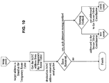
- the Temporary Route Table takes precedence over the Neighborhood Table and the Route Table. Referring to Figure 10 , the Temporary Route Table is accessed and the MAC destination address associated with the mesh layer target address is selected. The frame is then transmitted. If the MAC fails to transmit a frame, the Error Received condition is true and the Node tries to send the frame by an alternative route using Tree Routing or Mesh Routing.
- a mesh message from Node A sets the temporary return route in the table of Node B.
- a mesh message from Node C to Node A is routed to Node B.
- Node B's temporary return route to Node A has not expired and so it uses the route to send the message to Node A.
- Sometime later another mesh message from Node A restarts the temporary route expiration timer.
- TEMP_ROUTE_TO no new messages from Node A arrive and Node B deletes the temporary return route to Node A.
- the number of temporary return routes that can be stored is limited. If the limit is reached, the oldest temporary return route is deleted when a new temporary return route is created.
- a route discovery process is performed when a Node needs to create or trace a new route within the mesh network. It consists of a mesh broadcast of a Route Request message which is propagated through the network based on Route Request Acceptance Conditions. Once received by the target Node, a Route Reply message is returned to the originator leading to the creation of a new static route in both directions.
- Route Request acceptance conditions are verified by each Node receiving a Route Request message. This verification algorithm allows a Router to forward or stop the propagation of a Route Request. When acceptance conditions are satisfied, the Router from which the Route Request message was received is keep as a Route Candidate. A Route Candidate can be replaced based on Route Request acceptance conditions during the route discovery process to improve routing. Route Candidates are used at the end of the route discovery process when the Route Reply message is sent back to the originator. A Route Request is accepted as the first Route Candidate if it meets all of the following conditions:
- the request is received through a link with a minimum LQI class (defined later) at least equal to the requested one.
- a minimum LQI class defined later
- Route Requests received from non-neighbor Nodes are accepted if the requested minimum LQI class is "Unreliable link.”
- a Route Request is accepted for Route Candidate upgrade if it meets all of the following conditions:
- the overall route discovery process is summarized in Figure 12 which illustrates the simplest case, i.e., without any Route Candidate upgrade.
- the effect of a Route Candidate upgrade is shown in Figure 13 , in which the return path is updated during the route discovery process.
- the originator broadcasts a Route Request with a minimum LQI class of "Reliable link.”
- Every Router receiving the Route Request accepts or rejects the request based on conditions discussed above. If the Route Request is accepted as a first route candidate and the Router is not the target destination, it creates a route candidate to the originator and rebroadcasts the Route Request. If the Router is the target destination, it starts a timer of RREQ_RX_TIME milliseconds and creates a route candidate to the originator.
- the Node upgrades its route candidate without re-broadcasting the Route Request.
- the destination Node converts its route candidate into a static route and sends a Route Reply to the Next Hop of the route just created.
- Each Node receiving a Route Reply converts its route candidate into a static route to the originator. It also creates a static route entry to the destination. The Route Reply is then forwarded to the originator.
- the originator does not receive a Route Reply after the RREQ_TO timeout period (700 ms by default), it broadcasts a second Route Request with a minimum LQI class set to "Average link.” If this second attempt fails, the originator tries a third and last attempt with a minimum LQI class set to "Unreliable link.” If the three attempts of broadcasting a Route Request fail, an error is returned to the upper layer.
- Figure 12 illustrates the Route Discovery process with no Route Candidate upgrade.
- Figure 13 illustrates the Route Discovery process with Route Candidate upgrade. If the trace route option is set in the Route Request message, the target Node will set the trace route option in the Route Reply message.
- intermediary Routes create a temporary route instead of a static route and the route is recorded in the Route Reply message.
- the originator of the request can subsequently use the temporary route or source routing to reach the destination.
- Each Route Request is identified by a unique combination formed by the originator's short address and the Request ID. It is then possible to identify a Route Request already received from another Node.
- Route Establishment is a process in which a Node asks the Coordinator for a source route to another Node.
- the originator Node uses the target's 8-octet long address in its request.
- the Coordinator constructs a route using its current knowledge of the SM network.
- the Neighbor information contained in the periodic Keep Alive Request messages sent by Nodes is a prime source of information used by the Coordinator to construct routes.
- the Route Establishment response contains the source route to the target and the target's assigned short address.
- a route established from Node-A to Node-B is used for one-way communication. When Node-A sends a message to Node-B that requires a reply, Node-B uses the temporary route set up along the route by Node-A's message.
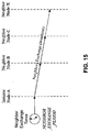
- the neighbor exchange process is performed by all Nodes on a periodic basis.
- the Neighbors Exchange process is used to update neighbor information and routing tables.
- Each Node in the network generates a periodic Neighbors Exchange message.
- All Nodes receiving the request update their Neighborhood Table.
- Figure 15 shows one Neighbor Information Exchange broadcast message transmitted by Node-A, which is received by Nodes B, C and X.
- Tree optimization is a recurrent process performed by all Nodes to ensure the network's optimal performance.
- the preferred route toward the Coordinator is re-evaluated after each Neighbors' Exchange message is received.
- the "Avg LQI" factor is omitted for tree optimization; it is used only at association when a Node selects its initial preferred route. Only one route change is allowed per 6 cycles of NEIGHBORS_EXCHANGE_PERIOD to provide enough time for the information to propagate in the network. This delay limits the rate at which Child Nodes change their route when the route quality improves.
- Each Node on the network shall report its presence to the Coordinator from time to time using Keep Alive Request messages to maintain its association status.
- the reporting period is determined by the CHECKPOINT_PERIOD and is typically set to be one hour.
- the period between Keep Alive messages should be constant as specified by the Keep Alive Period field within the Keep Alive Request message.
- the Coordinator flags a Node as Non Responding if this Node fails to communication with it within the Keep Alive Period. If the Coordinator has not received a Keep Alive Request or a Power Event message in a specified time, it removes the device from is registration table.
- the Coordinator's timeout period for Keep Alive Request/Power Event messages can be as long as 90 days.
- the Checkpoint process is also used to: trace the latest tree route for subsequent requests using source routing; send network management information such as network statistics and neighborhood information; allow configuration of mesh layer parameters controlled centrally; and provide a window of opportunity for the upper layer batch traffic.
- the Checkpoint is initiated autonomously by each Node. Checkpoint reporting by each Node is distributed pseudo-randomly within the CHECKPOINT_PERIOD. If the Coordinator needs to have better control over timing of the traffic generated on the network, it can send a Keep Alive Initiate request prior to the autonomous transmission of the Keep Alive Request.
- the Keep Alive Initiate request relies on the routing information of the previous Keep Alive Request. If this information is out of date, the subsequent autonomous Keep Alive Request sent by the Node will reestablish a valid route. It is important to note that a Keep Alive Initiate request does not create an entry in the Temporary Route table, thereby allowing the subsequent Keep Alive Request to trace the currently optimized tree route.
- Node A sends a Keep Alive Request frame to the Coordinator as triggered by expiration of its CHECKPOINT PERIOD timer.
- the Coordinator receives the request and sends a Keep Alive Response frame.
- the originator Node does not retry the request if it does not receive a reply.
- SM network There are three security services provided by the SM network and protocol: privacy, authentication and authorization. Initially, though not all data transmitted throughout the SM network has to be kept private, there are instances where the data sent should be encrypted to protect it from discovery. For example, security key configuration information needs to be kept private. Additionally, data is authenticated in two ways. First the data's integrity is checked to make sure that it has not been changed when transmitted through the network. Data integrity is verified from the source to the destination through one or more hops in the mesh network. Like the data, the address is protected from being changed undetectably. If the key used to protect that address is unique to the source, then the authentication verifies the integrity of the source address and that the stated sender originated the message frame. Further, the operations in messages have permission requirements associated with them. Devices originating messages have authorizations configured in the SM network that give the devices the permission to perform operations that match the permission requirements.
- the SM network protocol provides security for management frames routed through the mesh. These routed frames may span more than one hop and therefore need end-to-end security.
- the security features used by the SM network protocol are authentication and authorization.
- the mesh layer operations do not require privacy, other than for the transmission of security keys, where the privacy is provided by encrypting the transported keys.
- the SM protocol provides data link security services for hop-by-hop message transmissions.
- the SM data-link protocol provides data and source authentication for each hop taken by the message. It also provides operation authorization for local communication with maintenance devices. This security level also provides replay protection for all local and routed communication. Table 3 summarizes the implemented security mechanisms in accordance with a preferred embodiment of the present invention, the behavior of data link and network level counters and the key type used for each message type.
- Table 3 Security Counter and Key type Summary Data link layer security Network layer security Security Counter sent When received Key type Security Counter sent When received Key type Route discovery Route Request MIC-32 Src. count > last (n) S None Route Reply MIC-32 Src. count > last (n) S None Route Error MIC-32 Src. count > last (n) S None Routed services Data transfer MIC-32 Src. count > last (n) S None Power Event MIC-32 Src. count > last (n) S None Ping Request MIC-32 Src. count > last (n) S None Ping Response MIC-32 Src.
- the "[> last]” means the recipient of the frame, may accepts any counter value, playback rejection is not required since playback is already verified by the DLL security at each hop. Optionally, if the recipient has the memory to store the previously received counts it may reject frames where the count is not greater than the stored count.
- the "> last (n)” means the counter received must be greater than the RX Source DLL Nonce Count value maintained in the Neighborhood Table.
- the Neighbor Info Response frame initializes the RX Source DLL Nonce Count in the Neighborhood Table.
- the periodic Neighbor Exchange message maintains its currency in the absence of regular traffic between the two devices.
- the "> last (ed)” means the counter received must be greater than the last RX Source DLL Nonce Count value maintained in the End Device Table.
- the periodic End Device Data Request message maintains its currency.
- the "> last (rc)” means the counter received must be greater than the last RX Source DLL Nonce Count value temporary maintained for a selected Node and acquired in the Neighbor Info Response or Local Broadcast Response.
- the "last" counts are initialized to zero in the tables and then updated with the first authenticated reception.
- the following letters are used in Table 3 to define the key type used by each message type. "N" is (private) Node Key; "S” is Shared Mesh Key; and “M” is (shared) Maintenance key.
- the SM protocol provides a DLL Security service with data and source authentication using a message integrity check mechanism (MIC-32) as described in Annex B of IEEE 802.15.4:2006 which is incorporated herein by reference in its entirety.
- DLL security uses the SM DLL Security header to select the security key and set the nonce used in the crypto calculation.
- the format of the DLL Security header is shown in Figure 17 .
- the first fifteen bits (0 - 14) of the DLL Security header contains a portion of the transmitted nonce count.
- Bit 15 is the DLL Key ID that selects the current version of the key used to calculate the DLL MIC. This Key ID is used to coordinate the key used during a key change process by explicitly identifying which key was used in generating the DLL MIC.
- the MIC-32 data authentication calculation uses the calculation process described in the IEEE 802.15.4:2006 standard.
- the SM DLL nonce used for the MIC calculation is shown in Figure 18 .
- the DLL nonce used in the MIC calculation is thirteen octets.
- the DLL Security nonce combines the full DLL nonce count and the MAC layer source address used by the transmitting device.
- the Full DLL Nonce Count is five octets long, which ensures that its value does not repeat, within the lifetime of a key, at the frame transmission rates of SM devices.
- the address used in the MAC nonce is either the 8-octet long EUI address, or the 2-octet source PAN ID plus the 2-octet short address prefixed by four octets of all ones.
- the Full DLL Nonce Count can be based on either the Source counter or the Ticket counter.
- Ticket is acquired in the Local Broadcast Response or End Device Node Present messages
- the last authenticated value is stored only while communicating with a selected device Message Receiver
- the count value is acquired in the Neighbor Info Response or Neighbors Exchange messages.
- the last authenticated count is stored in the Neighborhood Table
- the count value is acquired in the Local Broadcast Response or End Device Node Present messages.
- the last authenticated value is stored only while communicating with a selected device Accepts received counts > stored count Accepts received counts > stored ticket Stores last authenticated count in the Maintenance Table Nonce Address MAC source long address, or 0xFFFFFF padding and MAC source PAN ID and short address MAC long address of the device that provided the ticket
- the five octets (bits 0 - 39) of the Full DLL Nonce Count are constructed using the following algorithm:
- the least significant octet (bits 0 - 7) of the transmitted nonce count is the IEEE 802.15.4 MAC header sequence number.
- the next 15 bits come from bits 0 through 14 of the DLL Security header's SM DLL Count.
- the 23 bits of the transmitted count forms the least significant bits of the counter portion of the SM DLL nonce.
- the receiver checks the least significant 23 bits of the transmitted count against the last authenticated RX Source DLL Nonce Count.
- the last authenticated RX Source DLL Nonce Count represent the Source Count acquired using a Neighbor Info Request and maintained in the End Device Table.
- the last authenticated RX Source DLL Nonce Count represents the Source Count acquired using a Neighbor Info Request and maintained in the Neighborhood Table. The Neighborhood Table entry is selected using the source PAN ID and MAC address of the received message.
- the last authenticated RX Source DLL Nonce Count represents the Source Count acquired using a Neighbor Info Response, a Local Broadcast Response or an End Device Node Present received and maintained temporarily for a selected Node.
- the transmitted count value is greater than the last authenticated RX Source DLL Nonce Count, then the transmitted counter bits (0 -22) are combined with the most significant bits (23 - 39) of the last authenticated RX Source DLL Nonce Count to form the Full DLL Nonce Count.
- the transmitted count is assumed to have rolled over if the transmitted count value is less than the value of the corresponding bits in the last authenticated RX Source DLL Nonce Count.
- the value in bits 23 through 39 of the last authenticated RX Source DLL Nonce Count is incremented by one before it is combined with the transmitted bits to form the Full DLL Nonce Count.
- the MIC-32 is calculated using the Mesh key generation specified by the DLL Key ID.
- the selected key and the Secure Full Mesh DLL Nonce are used to calculate the DLL MIC-32 value. If the calculated MIC-32 equals the transmitted MIC-32, then the message data integrity is validated and the message has not been received previously. In this case the last authenticated RX Source DLL Nonce Count is updated to the value of the Full DLL Nonce Count used in the MIC calculation.
- the SM DLL security nonce ticket counter process is used for all message types using the Ticket Counter as listed in the summary table in Table 3. This process is used for the secured non-routed DLL communications employed by Association Request/Response messages and by point-to-point messages. For these messages at least one of the MAC addresses has a long 8-octet format, the Maintenance Key is used, and the process is modified. The DLL Key ID selects the appropriate Maintenance Key and nonce count. The following algorithm is used to calculate the MIC.
- the five octets (bits 0 - 39) of the Full DLL Nonce Count are constructed using the following algorithm: the least significant octet (bits 0 - 7) of the IEEE 802.15.4 MAC header sequence number is combined with bits 0 through 14 of the DLL Security header. Together they form the 23 bits of the transmitted count bits of the DLL nonce count.
- the Ticket field in the Maintenance Key Table contains the last authenticated count received.
- the receiver checks the least significant 23 bits from the table and compares them to the transmitted count. If the transmitted count value is greater than the value in the corresponding bits of Ticket then the transmitted counter bits (0 -22) are combined with the most significant bits (23 - 39) of the Ticket to form the Full DLL Nonce Count. However, if the transmitted count value is less than the value of the corresponding bits in the Ticket, rollover of the transmitted count value is inferred. When this is the case the value in bits 23 through 39 of the Ticket is incremented by one before it is combined with the transmitted bits to form the Full DLL Nonce Count.
- the MIC-32 is calculated using the key specified by the Maintenance Key selected by the DLL Key ID and the Full DLL Nonce Count. If the calculated MIC-32 equals the transmitted MIC-32, then the data integrity is validated and the message has not been received previously. In that case only, the Full DLL Nonce Count is stored in the Ticket Count of the Maintenance Key Table.
- the DLL Security header MIC covers the SM message starting with the IEEE 802.15.4 Frame Control octet and continuing on through to the end of the payload. As shown in Figure 19 , the IEEE 802.15.4 physical layer preamble and the Frame Check Sequence are not part of the DLL Security calculation.
- the DLL Security header provides security for data authentication and operation authorization of SM messages that can travel one hop.
- the SM network security header provides end-to-end security for frames, which can travel multiple hops.
- the network security header provides authentication of data that is not dependent on trusting the intermediate routing devices.
- the network security header controls security for that portion of the SM frame that does not change as it is routed through the network.
- the network security header is present when the Originator Network Security Header flag is set as defined in the common mesh header described below
- the network security header is shown in Figure 20 . It is located in the SM header after the DLL Security header.
- the network security NET MIC-32 field is located at the end of the frame, before the DLL MIC-32 field and the IEEE 802.15.4 FCS field (see Figure 22 ).
- the receiver's SM application layer security process uses the Originator PAN ID and source address field of the received frame to determine if the frame is from the Coordinator or some other device.
- the Node Keys stored in the Node Key Table are used for communicating with the Coordinator.
- the Mesh Keys in the Neighborhood Table are used to communicate with other devices.
- bit 39 of the Network Security Header specifies the network Key ID, selecting Node Key-0 or Node Key-1.
- the bit selects Mesh Key-0 or Mesh Key-1.
- Routed messages are typically request/response messages.
- the response messages reflect the value of the Network Count in the request. Messages that require reflected counts are listed in Table 3.
- the SM network layer nonce is 13 octets long. Its structure is shown in Figure 21 .
- the combination of the Network Count, the Originator PAN ID and Address padded with zeros ensures the uniqueness of the nonce.
- the Network Count is reflected and it is combined with the Target PAN ID and address and the Originator PAN ID and address.
- Devices receiving request messages use the Network Count to verify the integrity of the payload data and optionally check for repeated count values to reject already received responses.
- Devices receiving responses to request messages check that the Network Count equals that in the request message. If it does not, the message is rejected. Response frames with repeated Network Count values also are rejected.
- the SM Network MIC-32 is authenticated using the following algorithm. First, the 39 bits of the Network Count is taken from the Network Security Header and padded with a zero to make a 40 bit field. This forms the counter portion of the network nonce. Next, the MIC-32 is calculated using the key specified by the Network Security header Key ID, using the Node Key for communications with the Coordinator and the Mesh Key for communications with other devices.
- the coverage of the Network Security header MIC is shown in Figure 22 .
- the Network MIC-32 provides authentication for almost all the SM frame's header field and payload.
- the portion of the SM frame's header field that is not covered by the Network MIC is the Max Remaining Hops field, which is decremented for each hop.
- Keep Alive Request messages have a second exception to the Network MIC-32 coverage: their Hop Addresses and Number of Hops fields.
- having two key in each of the Mesh Key Table and Node Key Table entries allows the Coordinator to set up new keys for devices without causing Network Security header MIC errors.
- Node-A prepares a request message for transmission by incrementing its source transmission counter and calculating the Network MIC. It then formats the request frame with the full five octet source transmission count in the Network Security header and transmits the message through Node-B to Node-C.
- Node-A stores the count used and starts a message response timer with a timeout set to MESSAGE_RESPONSE_TO.
- Node-C receives the request message and authenticates the Network Security header.
- Node-C prepares a response to Node-A using the same count value it received in the request. Node-A receives the response and checks that the count value is the same as what it transmitted.
- Node-A releases the stored count and stops the message response timer if the stored count is the same as the response count and the Network Security header is authenticated. If the tests fail and no other valid response frame is received in the timeout period, Node-A fails the request/response process and releases the stored count value.
- Messages transmitted between the Coordinator and a device that employ the Network Security header use the Node Key assigned to the device. Messages transmitted between devices that have a Network Security header use the Mesh Key.
- New devices associating with a network must be configured with the Node Key and Maintenance Key. This configuration may be done by the manufacture as a custom process for a purchaser, by a maintenance tool prior to association or over the network using the Service messages described further herein. Keys transported over the network must be encrypted for confidentiality. When sent in Service Response and Service Forwarding messages, the keys are generated by the Configuration Host and encrypted using the device's Device Key before being placed in the message payload. The Coordinator and the routing devices forward the encrypted keys without knowing the Device Key, so they are unable to eavesdrop on the value of the new key. This configuration process is between the device's application and the Configuration Host application. It is not part of the overall mesh protocol.
- the new device uses a Service Request message to talk to the Configuration Host.
- the outgoing Service Request message contains a Service MIC in the payload that is calculated using the manufacturer-supplied Device Key. (This Service MIC is not the DLL or Network MIC.)
- the routing device forwards the payload in a Service Forwarding message and the Coordinator sends the message to the Configuration Host.
- the routing device and the Coordinator do not have the Device Key and so they do not decode the MIC.
- the Configuration Host looks up the 8-octet device MAC address and finds the Device Key in its database.
- the Configuration Host sends a message to all Coordinators in the network that sets up a unique Node Key associated with the 8-octet device MAC address. This is a symmetric secret key that will be used for all secure communications between the Coordinators and the new device.
- Node Key-0 and Node Key-1 are set to the same value to avoid key synchronization problems as the system starts. This same value practice holds for the Maintenance Key-0 and Maintenance Key-1 values as well.
- the Configuration Host After sending the Node key to the Coordinators, the Configuration Host sends a response to the new device using a Service Forwarding Response or Service Response message, where the message payload contains the unique Node Key and the shared Maintenance Key, both encrypted by the new Node's Device Key. This response is sent back to the new device.
- the new device decrypts the Node Key and the shared Maintenance Key and stores them under the appropriate Key ID.
- a device that is newly introduced to a SM network has only a single cryptographic key: its factory-assigned permanent Device key, which is unique to the device.
- the device Before the device can participate in the SM network, the device must be commissioned with the network's Maintenance and Mesh keys, together with a device-unique Node key and a second system-assigned device-unique Device key. This commissioning may be made over the network itself, by direct wireless messaging to the device from a proximate commissioning device, or through some extra-protocol means, such as a direct connection to the device.
- the Maintenance, Mesh and Node keys are used to authenticate messaging within the SM.
- Node keys are used to authenticate and encrypt end-to-end network management messaging within the SM.
- the permanent Device key is used only to authenticate the newly introduced device to the SM network and to protect the system-assigned Device key when it is sent in response to the newly introduced Node.
- the system-assigned Device key is then used to protect the device's Node key and the shared Maintenance key when they are distributed to the Node. In subsequent messages, the device's Node key is used to protect the Mesh key whenever it is distributed to the Node.
- Receipt of a message that authenticates under the permanent Device key zeroizes all other keys, setting them to a "keyNotDefined" status, which restores a device's key state to that when it left the factory. This action protects the network against an attacker that has compromised the device's permanent Device key, perhaps by gaining access to the database of all permanent Device keys that exist at key repository, or to the subset database of Device keys of purchased devices that was delivered to the system owner.
- a secure association between a device and a Coordinator uses the Association Request and Association Response messages that employ the DLL MIC and Network MIC.
- the associating device uses the Maintenance Key Ticket count value for the DLL MIC and the Node Key and Originator count value for the Network MIC.
- the routing forwards the Association Request payload to the Coordinator in the Association Confirmation Request message.
- the payload also includes the 8-octet MAC address of the new device. This forwarding process is shown in Figure 24 .
- the Coordinator validates the Association Confirmation Request message DLL Security header and Network Security header. It then validates the embedded Network Security header constructed by the new device using the new device's Node ID and the Originator count in the Network Security header.
- the Coordinator looks up the Node ID using the 8-octet address in the Association Confirmation Request message in a data base that has been configured by a process outside the scope of the mesh protocol. For valid association requests the Coordinator constructs an Association Confirmation Response message.
- the message payload has the assigned short address of the new device, the Mesh Key Security Header, the Encrypted Mesh Key and the Mesh Key MIC32.
- the Mesh Key is encrypted using the new device's Node Key version as specified in the Mesh Key Security Header.
- the Coordinator constructs a Network Security header and that calculates the Network MIC using the Coordinator's reflected count in the new device's Network Security header and the new device's Node Key. This Network Header is carried as the payload of the Association Confirmation Response message shown in Figure 25 .
- the Mesh Key Security Header follows the same format as the 40-bit Network Security control word shown in Figure 20 with the Reflected Count Flag set to 0.
- the routing device that forwards the association response to the new device takes the payload of the Association Confirmation Response message and generates the Association Response message using the Maintenance Key and the router's Source count value to calculate the DLL MIC.
- the new device decrypts the Mesh Key using the Node Key with the Key ID specified in the Encrypted Key Security Header, it then verifies the Mesh Key MIC32 and stores the Mesh Key.
- Devices that change the primary Coordinator with which they are associated follow the same procedure as new devices. They use the same Association and Association Confirmation messages and the same Node Key and Maintenance Key.
- Preferred embodiments of the present invention institute key rotation practices; changing the security keys periodically or when a security event has occurred.
- the mesh keys used by a device are the Node Key, the Maintenance Key and the Mesh Key.
- the Coordinator changes these keys using the Keep Alive process and messages.
- Each device maintains two versions of each of these keys: Node Key-0, Node Key-1, Maintenance Key-0, Maintenance Key-1, Mesh Key-0 and Mesh Key-1.
- Each message sent has Key IDs in the DLL Security header and Network Security header that indicate which key is being used. In between key changes all the devices use only one version of each key for transmission and reception.
- the Coordinator writes the new key to the appropriate key and key version of each device. When the update process is finished and verified at most or all relevant devices, the Coordinator signals the devices to start using the new key for transmission. After all the devices are using the new key for transmission, the Coordinator deactivates the old key for reception.
- the Coordinator starts an update of a key by getting the current state of the current Write Key Toggle Bit associated with the key. It does this by waiting for a Keep Alive Request message from a device with the key as shown in Figure 26 .
- the Keep Alive Request message from the device contains the Write Key Toggle State field that tells it current status of the toggle bits for each key.
- the Coordinator then sends the key update using the Write Key parameter option in the Keep Alive Response message.
- the Coordinator verifies that the key has been updated by reading the change in state of the selected key's Write Key Toggle Bit in the next Keep Alive Request. The process is repeated if the key has not been changed.
- reception key selection is controlled by the DLL Security Header and the Network Security Header.
- the Coordinator tells the devices to start using the new key for transmission.
- the Coordinator waits for a Keep Alive Request message from a node using the new key as shown is Figure 27 .
- the Coordinator commands the node to switch to the new key for transmission. The switch is confirmed in the next Keep Alive Request message received from the device.
- the Coordinator deactivates the old key by waiting for a Keep Alive Request and then sending a Keep Alive Response containing the appropriate key deactivate command.
- the Coordinator verifies the deactivation in the next Keep Alive Request received from the device. This process is used to update Node Keys, Maintenance Keys, and Mesh Keys.
- the Process for changing a generic Key x, version 0, is depicted in Figure 26 . Note that only the Coordinator is allowed to originate a Keep Alive Response message with key control commands in it.
- FIG. 28 shows a new End Device, Node-A, requesting neighbor information and receiving. In this example there are two PANs and three neighbors. Based on the Association Ratio algorithm, Node-A selects the Coordinator on PAN 1. It also selects Node-B as its Parent using the Parent Selection algorithm. Node-A then sends Node-B an Association Request message, which Node-B converts to an Association Confirmation Request message addressed to the Coordinator. The Coordinator sends the Association Confirmation Response message back to Node-B.
- Node-B then sends the Association Response message to Node-A.
- Node-B adds Node-A to its End Device Table after receiving a Keep-Alive Request message from Node-A with the "Device Type" set to End Device type and the Receiver On When Idle bit reset (to off).
- This first Keep-Alive Request message also carries the Multicast Group Addresses list which is captured by Node-B for future filtering and forwarding of Multicast messages.
- the Coordinator receives the Keep Alive Request message.
- a Parent can remove a Node form its End Device Table if it has not received any Keep Alive Request messages from this Node for a period exceeding 24 hours.
- Message forwarding with a non-sleeping End Device is done as soon as received.
- a Non-sleeping End Device advertises its presence to its Parent and to the Coordinator in both the Association Request and the Keep Alive Request messages.
- the Device Type field is set to End Device type and the Receiver On When Idle is set.
- the Parent In the case of transmission by the Sleeping End Device, the Parent allows the End Device to return to sleep as soon as the transmission acknowledgment (802.15.4 ACK MAC-PDU) for the message is received. All frames sent to a Sleeping End Device (unicast, multicast and broadcast) are buffered by its Parent and transmitted to it when it is awake. If a response is expected, a Sleeping End Device wakes up every RESP_SLEEP_PERIOD until the expected response is received. If no response is expected the Sleeping End Device sleeps for the interval SLEEP_CHECK_PERIOD. The Sleeping End Device wakes up periodically at each SLEEP_CHECK_PERIOD to check for buffered frames. It also wakes up when it has a message to transmit. When it wakes up with a message to transmit it first checks for buffered frames before it transmits its own message.
- the Sleeping End Device frame forwarding process is illustrated in Figure 31 .
- the sleeping Node-A wake ups and checks for any frames buffered in Node-B by sending an End Device Data Request message.
- Node B replies with an End Device Response message with the "no Frame Pending" status that tells Node-A there are no frames buffered.
- Node-A then transmits a frame that does not require a response to a target application through its Parent, Node-B.
- Node-A waits for an ACK MAC-PDU from Node-B and then goes to sleep for SLEEP_CHECK_PERIOD. This sleep is interrupted when Node-A wakes up to transmit another frame.
- the new frame is a request that requires a response from the target.
- the request frame is routed to the target by Node-B.
- Node-A receives the MAC level ACK from Node-B, it restarts its sleep timer with a duration set to the value of RESP_SLEEP_PERIOD.
- Node-B forwards the request frame to the target application that then generates a response frame.
- Node-B receives and buffers the response frame for Node-A which is sleeping.
- Node-A wakes at the end of the time period and sends Node-B an End Device Data Request message and receives an End Device Response message with the Frame Pending bit set.
- Node-A waits for the stored frame for a maximum duration of MAX_MF_WAIT.
- Node-B sends the response frame in its buffer to Node-A before the MAX-MF_WAIT_PFRIOD.
- Node-A sends Node-B an ACK MAC-PDU and goes back to sleep with the timer duration set to the value of SLEEP_CHECK_PERIOD.
- Node-B releases the buffer when it receives the ACK MAC-PDU from Node-A.
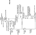
- FIG. 32 show the Sleeping End Device Checkpoint process.
- a message is received for Sleeping End Device, Node-A, and buffered by the Parent Node-B.
- Node-A wakes when its Checkpoint timer expires. It sends an End Device Data Request message to Node-B and receives an End Device Data Response message with the frame-pending bit set.
- Node-A then starts its listen timer with a duration of DATA_REQUEST_TIMEOUT and listens for a frame from Node-B.
- Node-B sends the buffered frame to Node-A, which stops the listen timer. The frame does not have the frame-pending bit set, which tells Node A that there are no more frames to receive.
- Node-A sets the Checkpoint timer with the duration CHECKPOINT PERIOD and goes back to sleep.
- Node-B releases the buffer when it receives the ACK MAC-PDU frame from Node-A.
- Node-A wakes up when its Checkpoint timer expires.
- Node-B has no frame stored for Node-A, so when Node-A sends the End Device Data Request message Node-B's replying End Device Data Response message does not have the frame-pending bit set.
- Node-A sets its Checkpoint timer with the CHECKPOINT_PERIOD and goes back to sleep.
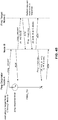
- This process exemplified in Figure 34 is used to initiate a point-to-point communication with a Sleeping End Device.
- Typical applications for this type of communication are between a handheld device and a sleeping End Device and occur during installation, operation, and maintenance processes.
- a physical trigger (button, reed switch + magnet) initiates Local Communication. This sets the Sleeping End Device in local communication mode.
- the Sleeping End Device then sends an End Device Node Present message with a periodicity of END_DEVICE_PERIOD and listens for the interval END_DEVICE_WAIT for any command sent in response.
- the Sleeping End Device stays in the local communication mode for the time interval determined by the END_DEVICE_INACTIVE_TO parameter after each frame is received or transmitted.
- a Sleeping End Device receives an external trigger that puts it in a mode where it looks for a local device with which to communicate. It transmits an End Device Node Present frame and starts two timers.
- the first timer is the end device notification timer, END_DEVICE_PERIOD, which determines how long the Sleeping End Device listens for a response to the notification message.
- the second timer is the end device notification process timer. It determines how long the Sleeping End Device remains in the state where it is looking for a local device.
- Node-A sends one End Device Node Present message that is not heard by the local device.
- the end device notification timer After the end device notification timer expires, it sends a second End Device Node Present message that triggers a second response by the local device.
- the ACK MAC-PDU from the local device terminates the two timers and puts Node-A in the local communication mode. In this mode Node-A starts the end device communication timer that is set with a duration specified by the LOCAL_COM_TO parameter.
- the local device sends Node-A a frame that resets the timer.
- Node-A initiates a frame of its own to the local device. This transmitted frame also resets the timer.
- the ACK MAC-PDU does not reset the timer, which then expires, causing Node-A to exit from the local communication mode.
- Dedicated Routers allows the deployment of multiple Coordinators at the same physical location. This approach consists of deploying multiple Routers, possibly with directional antennae, where each Router is dedicated to a specific mesh network / Coordinator.
- a Dedicated Router has the following specific behavior: a Dedicated Router is associated to a specific Network Name and is manually configured with this name and a Dedicated Router can associate only to the Coordinator or another Dedicated Router; it is not allowed to associate with a normal (non-dedicated) Router. This restriction is imposed to avoid the situation where a Dedicated Router works for some time until its environment changes in such a way that it is no longer capable of establishing a route to its Coordinator.
- a Dedicated Router For the computation of the association ratio, a Dedicated Router is seen as a no-hop-distant device similar to a Coordinator. This guarantees that surrounding devices will prefer the Dedicated Router over other Routers for their association.
- Dedicated Router sets the Dedicated Router Flag in the Neighbor Info Response message. Nodes receiving Neighbor Info Response message with the Dedicated Router Flag set shall consider it to be as a no-hop-distant device when computing its Association Ratio.
- the following mechanisms are provided to control the flow of messages on the network and to provide some control on message latency.
- Most traffic is either sent from or to the Coordinator. Message latency is directly affected by the way the Coordinator manages this traffic. Internally, the Coordinator orders messages based on the importance of the associated task and the notion of priority implemented by the application layer. In the case of the ANSI C12.22 application layer, this notion of priority takes the form of the URGENT flag carried in the Calling AE Qualifier element.
- the protocol allows the Coordinator to control the timing of the Checkpoint process at each Node. To do this, the Coordinator sends a Keep Alive Initiate message to each Node before the end of that node's CHECKPOINT_PERIOD.
- Frames routed within the mesh network have an Urgent flag, which when set permits the Router to reorder outbound frames when there are other frames of lesser priority in the transmit queue. Nodes are not permitted to use the entire network capacity for any extended period of time. In the network protocol, this throttling is provided by a single-frame transmission window with an end-to-end acknowledgment.
- a mesh forwarding process is required for support services that are used before a Node has associated with a network.
- This forwarding process allows the unassociated Node to communicate with service hosts such as commissioning or location tracking hosts on a LAN or WAN segment.
- the commissioning process is implemented by the application.
- the secure mesh protocol does not determine how commissioning is done, but it does support over-the-network commissioning using the Service and Service Forwarding messages. When used, these messages convey the Node Key and Maintenance Key that will be used by the device so that it is able to run the Association processes. Alternatively, the device could be commissioned with these keys during manufacturing.
- the forwarding process is illustrated in Figure 35 .
- the requesting device issues a Neighbor Info Request frame and listens for Neighbor Info Response frames. This is the same process used when the device associates with the network.
- the neighbor information process is shown in Figure 3 .
- the device uses the Association Algorithm to pick the neighbor to use as a proxy for service message forwarding.
- the requesting device Node-A, places the service message in a Service Request frame addressed to the selected neighbor, Node-B.
- the Service Request frame identifies the service the message is to go to in the mesh header in the "Server" field.
- the Service Request frame is then transmitted to Node-B.
- Node-A starts a "halt service request timer" when the MAC ACK is received from Node-B. This timer is set with the parameter SERVICE_PERIOD that prevents Node-A from sending more service frames until the timer has expired.
- Node-B recognizes the Service Request frame from its "service type” and “service code” fields. It processes the frame by assigning the forwarding process for Node-A a "Requestor id” value and sending the contained information to the Coordinator in a Service Forwarding frame. Node-B starts a "halt service request RX timer" when it successfully transmits the Service Forwarding frame. The timer is set with the SERVICE_PERIOD parameter. While the timer is active, Node-B does not accept additional Service Request frames from any Node, including from Node-A.
- the SERVICE_PERIOD timeout set by both Node-A and Node-B is cancelled as soon the service host accepts servicing the request as indicated by an appropriate service reply.
- the SERVICE_PERIOD timeout is reestablished for each new Service Request frame that is sent.
- the Coordinator receives the Service Forwarding frame from Node-B. It registers the "Requestor ID” value and Node-B's address. The Coordinator sends the service message contained in the Service Forwarding frame to the service host identified in the "Server Requested" field. When the service host responds, the Coordinator puts the service message in a Service Forwarding Reply frame and addresses it to Node-B. The Coordinator also fills in the "Requestor id" value for Node-A. The Coordinator sets a "Service keep-alive timer" that will release the forwarding process if it is inactive for the duration SERVICE_TO. Releasing the forwarding process for Node-A removes the Node-A's "Requestor id" from memory.
- Node-B receives the Service Forwarding frame from the Coordinator and looks up the "Requestor id" to identify Node-A as the destination. The receipt of the Service Forwarding frame sets Node-B's "Service keep-alive timer" for the duration SERVICE_TO. If the timer expires before another Service Forwarding frame is received for Node-A, the Node-A "Requestor id" is released. Node-B constructs the Service Requestor response frame and sends it to Node-A.
- Node-A receives the Service Requestor response frame and extracts the host's service message.
- the receipt of the Service Requestor response frame sets Node-A's "Service keep alive timer" for the duration SERVICE_TO. If Node-A does not receive another host message in this time, it times out the service-request process. If later there is another message generated to a host, the service-request process is restarted from the beginning with a new Neighbor Info Request frame.
- Every Node in the mesh network can notify the Coordinator rapidly after it loses power or when the power is restored.
- the performance goal for the process is to have most Nodes notify the Coordinator within one minute after their status changes. Those Nodes that take longer should not exceed the three minutes of backup power provided by the Nodes implementing the Power Outage Routing option as advertised by the Neighbors Exchange service.
- the system load induced by this process is a critical consideration because every Node may need to communicate in a very short time. Power event report aggregation and low overhead tree routing are employed to reduce the amount of system communication capacity used for this reporting.
- Figure 36 shows the overall process used by a Node to report a power event. The process starts with a Node detecting a power event and waiting to make sure it is not a transient. For an event to be reported, it has to last more than the time defined by the PO_RECOGNITION_PERIOD parameter.
- any Node that has a power event that passes this transient-suppression test goes into the PO_AGGREGATE_PERIOD round.
- the leaf Nodes - Nodes without any Children in their Neighborhood Table - and first hop Nodes report their event in this round.
- each reporting Node transmits at a pseudo-randomly-chosen time within the interval whose duration is PO_AGGREGATE_PERIOD. Nodes receiving events during this interval aggregate these events for later transmission.
- non-aggregating Nodes are free to piggyback their event report to any of the Power Event Report frames that they may route; however, aggregating Nodes must initiate their own Power Event Report frame since the eventual acknowledgment they receive for the forwarded aggregated event reports needs to be broadcast to the aggregator's neighbor Nodes.
- the Coordinator receives power event reports and sends acknowledgements. These event acknowledgements follow a source route constructed from the entries in the Power Event Report. Because of this, the acknowledgement message follows the reverse route of the report and confirms the reception to each Node reporting an event.
- Each such Node schedules a transmission time pseudo-randomly within the following interval of duration PO_RETRY_RND_PERIOD. This round is repeated until the event report is acknowledged or the backup power is exhausted. Nodes acknowledged prior to a scheduled power event reporting transmission do not initiate that transmission, even if they had entered into the retry round. Nodes reporting a power event do not initiate any Data Transfer messaging of their own while they are in any of the power event reporting rounds. All event Nodes continue to route the messages they receive.
- Figure 37 shows an example of the power outage reporting for a non-leaf Node that is multiple hops away from the Coordinator.
- Node-A detects a power outage and waits for the time given by PO_RECOGNITION_PERIOD to confirm that the outage is not a transient.
- Node-A stops initiating Data Transfer messages and does not resume until power is restored. After the recognition interval, Node-A waits for an interval given by the parameter PO_AGGREGATION_PERIOD to collect events from neighboring Nodes. While in the aggregation state, Node-A does not forward Power Event Report frames to the Coordinator unless the message contains event reports from multiple Nodes.
- Node-A enters into the PO_RND_PERIOD round. Node-A delays for a pseudo-randomly chosen time within the interval of duration PO_RND_PERIOD before sending a Power Event Report frame. If Node-A needs to route a Power Event Report frame during this delay and has no events aggregated, it piggybacks its own report and sends the resulting frame to the next hop.
- Node-A At the end of the delay, if Node-A was not able to piggyback its event, it initiates its own Power Event Report frame including any additional aggregated events.
- Node-A After sending or piggybacking its event report, Node-A expects an acknowledgment from the Coordinator. In Figure 37 , Node-A receives this acknowledgement and so it does not enter into a retry state at the end of the current round. Even though Node-A does not go into a retry round, it continues to route messages until its backup power is exhausted.
- Figure 38 depicts the process in which Node-A fails to get an acknowledgement for a power event report and has to retransmit the report.
- the actions taken by Node-A are the same as those in the failure-free case shown in Figure 37 until the acknowledgement from the Coordinator is lost in the PO_RND_PERIOD round.
- Node-A goes into a retry round.
- the retry round lasts for the time determined by the PO_RETRY_RND_PERIOD parameter.
- Node-A selects its retry transmit time pseudo-randomly within the period and resends a power event report containing its address.
- Node-A does not have to originate a retry frame if it has an opportunity to add its event report to a routed Power Event Report frame while in the retry round.
- Node-B is a neighbor of the Coordinator.
- One-hop Nodes can transmit their reports to the Coordinator in the PO_AGGREGATE_PERIOD round.
- Node-B transmits the power event report after a pseudo-randomly-chosen delay and receives an acknowledgement. If the acknowledgement were not received, the Node would retransmit the event report in the following PO_RND_PERIOD round.
- Leaf Nodes transmit their reports during the PO_AGGREGATE_PERIOD round.
- Figure 40 shows a typical leaf Node power event reporting process.
- a Leaf Node, Node-C chooses a pseudo-random time within the interval of duration PO_AGGRETATE_PERIOD to transmit its power event report. The acknowledgement for this report may not be received until near the end of the interval of duration PO_RND_PERIOD. In this case Node-C receives the acknowledgement and its power event reporting process is completed. If an acknowledgement is not received, Node-C enters an interval of duration PO_RETRY_RND_PERIOD and retransmits the event report. This continues until Node-C runs out of backup power or an acknowledgement is received.
- Tree routing is normally used to send power outage/restoration event notification frames. Mesh routing may also be used as an alternate method if the Node has been waiting to send its event for more than the time set by the parameter POWER_REPORT_WAIT.
- Power restoration reporting uses the same process and messaging as power outage reporting, except that the parameters PO_RND_PERIOD and PO_RETRY_RND_PERIOD are replaced by the parameters PR_RND_PERIOD and PR_RETRY_RND_PERIOD.
- power outage and power restoration notifications may be done to any of the registered networks. Different Coordinators are selected in round-robin fashion at each attempt of reporting a notification. Attempts to send power restoration notifications are repeated up to the duration RESTORATION_TIMEOUT. Nodes that are not members of overlapping networks initiate an Association process after waiting an interval whose duration is RESTORATION_TIMEOUT. After a successful Association, the associating Nodes do not need to send Power Event Report messages since the Association process itself sets the Coordinator's state for the Node to "Alive.”
- a mesh multicast service is used to send application level information to a group of Nodes that share the same group address.
- a group address is a 2-octet short address within the range 0x3000 to 0x3FFF.
- Group addresses are well known or configured, with well known addresses assigned from address 0x3FFF and decreasing while configured addresses are assigned from address 0x3000 and increasing.
- the mesh layer does not provide services to configure group addresses; such assignment needs to be made by the application layer from a centralized location such as the Coordinator.
- a Mesh multicast service consists of a local broadcast by the originator of the multicast message.
- Each Router receiving this message verifies: that the message has been received from an authenticated Node listed in its Neighborhood table; and that the message Originator address and Request ID do not match those of a previously processed message.
- the Router then verifies that the Target Address matches one of its own group addresses. If a match is found, the message is propagated to the Router's upper layers for processing.
- the Router also determines whether the Target Address matches a group address of its child End Devices. If so, the message is sent to each child End Device having a matching group address. A copy of the message is saved for each Sleeping End Device with a matching group address.
- Child-group-addresses are acquired by a Parent Router by inspecting the first Keep Alive Request message sent by each child End Device after the End Device chooses or changes its primary parent. Routers do not forward group-addressed frames to End Devices for which they are not primary parents.
- Multicast Data Transfer frames with a Max Remaining Hops field greater than one are re-broadcast.
- the Router To re-broadcast a message the Router first decrements the Max Remaining Hops field and broadcasts the resulting message to its own neighbors. Duplicate multicast messages are ignored based on the messages' Originator address and Request ID as specified previously.
- the Max Remaining Hops field can be used to limit the region for which a multicast is sent.
- a Coordinator should set the Max Remaining Hops field to the value MAX_HOPS.
- a non-Coordinator Node should set the Max Remaining Hops field to twice the value MAX_HOPS.
- All SM nodes in a group have the well known group address shown in Table 5.
- Table 5 - Well known group addresses Address Group 0x3FFF All SecureMesh Nodes
- Node-X initiated the multicast data transfer, which progressed through the mesh network until it reached Node-A and Node-B, where Node-A is a neighbor of Node-B and Node-C, and Node-C is a neighbor of Node-D, but Node-B is not a neighbor of Node-C.
- Node-A receives the Multicast Data Transfer frame and checks the Originator Address and Request ID. Because it appears to be a previously-unreceived multicast frame and the value of the Max Remaining Hops field is greater than one, Node-A forwards the frame after decrementing the value of the Max Remaining Hops field.
- the forwarded frame goes to Node-B and Node-C. Both Node-B and Node-C also forward the frame to their neighbors.
- the frame forwarded by Node-C goes to Node-D where it is not re-forwarded because the value of the Max Remaining Hops field in the received frame equals one.
- Node-B receives the multicast frame via another route. This duplicate frame carries the same Originator Address and Request ID as the prior frame, so it is discarded and not forwarded.
- the local communication process is used to initiate point-to-point communication between two Nodes that may not already be part of the same mesh network. Typical applications that use this type of communication are installation, operation and maintenance activities and walk-by reading of Nodes using a handheld reader.
- Local communications use the Node's long 8-octet IEEE EUI-64 address rather than its short 2-octet address.
- the handheld device issues the Local Broadcast Request frame to initiate local communication. From the responses to this local broadcast, the handheld device can build a table of local devices that are awake, where each table entry includes the following information about the responding Node: long and short addresses;
- PAN IDs PAN IDs
- Device Class information PAN IDs
- the user can select the device with which to communicate.
- Figure 42 shows a typical local communication sequence.
- the handheld device discovers the local nodes by transmitting a Local Broadcast Request frame. This message is answered by Node-A and Node-B.
- the handheld application selects Node-A and sends it a Local Data Transfer frame that executes an application service such as a read operation.
- Node-A responds with a Local Data Transfer frame containing the application response. All frames except the first broadcast frame are acknowledged with MAC-level ACKs.
- the Range Test process uses the local communication Range Test Request and Range Test Response frames.
- the Range Test Request command frame is used to check whether Node is reachable in the local communication mode.
- the Range Test Response frame reports the signal strength as recorded by the responder in the forward direction. The signal strength of the response is measured by the range test originator to determine signal strength in the return direction.
- the Range Test Initiate and Range Initiate Result frames can be used to request one Node to perform a range test with a different Node and to report the test results to the requester.
- a typical example of this function is for a handheld test tool to request a Router to do a range test with an End Device.
- Figure 43 shows this process, where a handheld device requests Node-A to perform a range test with Node-B.
- the Range Test Initiate sent to Node-A tells it to send a Range Test Request to Node-B.
- Node-B receives the request and records its modem's RSSI and LQI values as measured during request frame reception.
- Node-B then sends a Range Test Response to Node-A, which records its modem's RSSI and LQI values as measured during response frame reception .
- Node-A then sends a Range Test Result to the handheld device, reporting the RSSI and LQI values for both the Range Test Request and Range Test Response frames between Node-A and Node-B.
- the FRR test is used to evaluate the one-way link quality between a sender and a receiver. Theses two Nodes need to be able to reach each other directly.
- the sender sends a configurable number of frames in local communications mode to the receiver.
- the receiver sends a result frame to the sender. This frame contains the FRR and the average LQI for received frames.
- a frame reception rate session consists of: the transmission of the Frame Reception Rate Test Init message; multiple transmission of the Frame Reception Rate Test Data messages; the transmission of the Frame Reception Rate Test End message; and the reception of the Frame Reception Rate Test Result message.
- Frame Reception Rate Test control messages are transmitted with MAC layer acknowledgment and retry. In the case of a MAC layer transmission failure, such control messages are re-transmitted up to a maximum of FRR_TEST_RETRY times.
- FIG. 44 An example of the frame reception rate test process is shown in Figure 44 .
- a handheld initiates the test in this example by sending the Frame Reception Rate Test Init message to Node-A.
- the test is set to send N test frames without acknowledgements.
- the handheld starts sending the first of the N test frames to Node-A after it receives the ACK from Node-A for the test-initializing message.
- the Frame Reception Rate Test End message is sent after the N test frames.
- the test end message is acknowledged by Node-, which then sends the Frame Reception Rate Test Result v to the testing handheld.
- the ping command is used to check whether a Node is reachable through the mesh network, and to determine and trace the routes used for each direction of communication.
- the Ping frame tests the ability of a device to reach a Node that is more than one hop distant, since testing of the first hop is provided by Range Test commands.
- a Ping Request can be used by a Coordinator to determine whether a device that is awake is reachable in the intervals between Keep Alive Requests.
- the Ping Request frame can be used with any type of routing. As the frame traverses each Node, the RSSI and LQI values measured during frame reception are noted. Both values are added to the frame before it is forwarded.
- the addressed receiving device processes the Ping Request frame, converts it to a Ping Response frame, and sends that response back to the originating device.
- the RSSI and LQI values measured during frame reception on the return path are appended to those accumulated as the Ping Request frame traversed its forward path.
- Node A initiates a Ping Request message targeting Node-C.
- the frame within the Ping Request message is routed through Node-B.
- Node-B updates the frame data by incrementing the hop count, and appending its 2-octet address, the measured RSSI and the observed LQI to the Ping Request frame's accumulated data before forwarding the frame to Node-C.
- Node C converts the received Ping Request frame to a Ping Response frame and sends it to Node-A.
- the Ping Response frame arrives at Node-A, it contains the path traversed by the request and response frames and the measured RSSI and observed LQI values noted at each hop.
- the SM frame structure is presented so that the leftmost or first-described field is transmitted or received first. Except for octet arrays, all multi-octet fields are transmitted or received least significant octet first. To maintain compatibility with the IEEE 802 standards, addresses and PAN identifiers are considered octet arrays and are transmitted unaltered, which is equivalent to transmitting them most significant octet first when viewed as multi-octet fields.
- Each frame described in this document includes MAC layer fields, which are documented within the mesh layer to provide the context on which the mesh layer operates.
- the MAC and mesh layers are tightly coupled, so that information required by the mesh layer that is already present at the MAC layer is not duplicated.
- Descriptions of the MAC layer fields are provided in this subsection so that they need not be duplicated in the description of each mesh-layer frame format. More information on these fields can be found in the IEEE 802.15.4:2006 standard, which is the controlling specification for the MAC protocol and is incorporated herein by reference in its entirety.
- Intra-PAN Bool 6 Specifies whether the MAC frame is to be sent within the same PAN (intra-PAN) or to another PAN (inter-PAN). When set and both destination and source addresses are present, the frame contains only the destination PAN identifier field.
- Sequence Number Unsigned 8 bits Specifies a unique sequence identifier for the frame.
- the sequence number field is used to match an acknowledgment frame to the data or MAC command frame as specified in the IEEE 802.15.4:2006 standard.
- the SM MAC Header Flag is set to 1: the Sequence Number is the least significant octet of the MAC nonce counter, Destination PAN Identifier Binary 2 octets Specifies the unique PAN identifier of the intended recipient of the frame.
- a value of 0xFFFF in this field is the broadcast PAN identifier, which is accepted as a valid PAN identifier by all devices currently listening to the channel. Presence of this field is defined by the Destination Addressing Mode field. Destination Address Binary 2 octets Specifies the address of the intended recipient of the frame. A value of OxFFFF in this field represents the broadcast short address, which is accepted as a valid short address by all devices currently listening to the channel. Presence and content of this field is defined by the Destination Addressing Mode field. Source PAN Identifier Binary 2 octets Specifies the unique PAN identifier of the originator of the frame.
- Source Address Binary 2 octets Specifies the address of the originator of the frame. Presence and content of this field is defined by the Source Addressing Mode field.
- FCS Unsigned 16 bits 2-octet ITU-T CRC as specified by IEEE 802.15.4, without the initial preset or final complementation typical of a frame check sequence (e.g., as in IEEE 802.3).
- Bits 4 to 6 of the first octet of the Mesh header are called the Service type. This field defines the structure of the next of the mesh header and the general behavior of a group of messages. With the exception of the Data Transfer frame, the subsequent header prefix contains a field called Service Code which defines the specific message format for the last of the mesh header. Table 7 enumerates all defined combinations of Service Type and Service Code.
- This message frame format shown in Figure 46 is used to transport upper layers information for all requests and responses.
- Table 9-Fields (Tree and Mesh routine) Field Name Data type Description Common MAC layer fields See description herein. Unsigned 8 bits See sub fields below: Source Route Present Bool 7 Reset Service Type Bits 6-4 Set to 0 Urgent Bool 3 Set when the message is urgent and should be forwarded immediately before any other less-urgent pending transmission.
- DLL Security Header Flag Bool 1 Set when the DLL Security Header follows this octet Network Security Header Flag Bool 0 Reset, no Network Security Header follows [DLL Security Header]
- Unsigned 16 bits See description herein.
- Unsigned 8 bits See sub fields below: Sibling Transmission Bool 7 Set when a frame is transmitted using tree routing and if a local repair is done through a Sibling instead of a Parent. Only one Sibling transmission is allowed per tree level; when a Node receives a frame with this flag set, it can only route this frame to one of its Parents. Max Remaining Hops Unsigned bits 6-0 Set to MAX_HOPS by the originator of this message and decremented each time a message is routed.
- Target Address Binary 2 octets Short address of the final target (Router or End Device) of this message. Originator Address Binary 2 octets Short address of the originator (Router or End Device) of this message.
- Target PAN Identifier Binary 2 octets PAN identifier of the target Node as identified by the Target Address field. Originator PAN Identifier Binary 2 octets PAN identifier of the originator Node as identified by the Originator Address field. Payload Multi-octet Upper layer information. [DLL MIC32] Binary 4 octets See description herein.
- the Node is part of the network with the PAN identifier as specified by the third entry in the PAN Identifiers list.
- 3 The Node is part of a network which is not listed in the PAN Identifiers list. When this option is used, the frame can be routed to the incorrect Node in the following circumstances: ⁇ More than four networks exist within the same geographical area ⁇ Multiple Neighbors exist with the same short address but on non-listed networks. Originator Address Binary 2 octets Short address of the originator (Router or End Device) of this message. Bits 15-14 define the PAN identifier of the network of which the target Node is a member. See the Hop Addresses field (following) for more information on these 2 bits.
- Unsigned 8 bits See sub fields below: Number of PAN identifiers Bits 7-6 Defines the number of entries in the PAN identifiers field. Number of Hops Addresses Bits 3-0 Number of Addresses in Hop Addresses list. Source routing is used when the Target device is more than one hop away. Therefore the Number of hops is at least one.
- PAN Identifiers Array of Binary 2 octets List of Network identifiers. Bits 15-14 of the different short addresses specified within this frame reference this list. Each short address is explicitly associated with one of the three specified PAN Identifiers, or none of them.
- Hop Addresses Array of Binary 2 octets Short address of each Node responsible for routing this message. Bits 15-14 define network membership of the Node as described by the PAN identifiers field. Payload Multi-octet Upper layer information. [DLL MIC32] Binary 4 octets See description herein.
- the mesh multicast message format set forth in Figure 47 facilitates multicast of application data to a group of Nodes within a mesh network.
- Group addresses need either to be pre-assigned or assigned by an upper layer. This layer does not provide services to remotely assign group address to Nodes.
- Originator Address Binary 2 octets Short address of the originator (Router or End Device) of this message.
- Request ID Unsigned 8 bits Unique number used to eliminate duplicated message during a broadcast storm.
- Unsigned 8 bits Last Fragment Bit 7 Flag which indicate the last fragment of a fragmented multicast. Fragment ID Bits 0 to 6 When a multicast is fragmented, each fragment has a unique fragment number from 0 to n where n represent the last fragment which is identified by Last Fragment flag set to true.
- the route request message is used to create a route to a target Node for peer to peer communication between two Nodes using mesh routing.
- the route request message format is shown in Figure 48 .
- Service Code Unsigned 8 bits Set to 1. Unsigned 8 bits See sub fields below: Trace Route Flag Bool 0 When set, the response contains the list of hops used to route to the target Node. When this option is used, the network is not updated with the routing information; Routers do not create a route in their routing table. Min LQI Class Bits 2-1 Used to set a minimum link quality for each hop of the requested route. Before accepting this request, each Node validate that the LQI class corresponding to the Node from which this message have been received is better or equal to the value of this field.
- Hop Count Unsigned 8 bits Use to count the number of hops from the Requestor Address. Initially sent with a value of zero and incremented each time this request is received and re-broadcast. Request ID Unsigned 8 bits Unique number used to eliminate duplicated message during the broadcast storm. Requested Address Binary 2 octets Node for which a route is requested. Requestor Address Binary 2 octets Originator of this Route Request. Hop List Array of Binary 2 octets Address of each Node routing this message. The size of this list is Hop Count minus one. Present if the Trace Route Flag is set. Padding Binary 2 octets For backward compatibility. DLL MIC32 Binary 4 octets See description herein.
- the route reply message is sent in response to a Route Request and is given the format shown in Figure 49 .
- Trace Route Flag Bool 0 Return the same value as the Trace Route Flag received in the Route Request.
- Requested Address Binary 2 octets Node for which a route have been requested.
- Requestor Address Binary 2 octets Originator of the Route Request.
- Hop Count Unsigned 8 bits Number of hop between the Requestor Node and the Requested Node. Set to 1 if the Requestor Node is a neighbor of the Requested Node [Hop List] Array of Binary 2 octets Address of each Node routing this message. The size of this list is Hop Count minus one. Present if the Trace Route Flag is set. [DLL MIC32] Binary 4 octets See description herein.
- the route error message is sent out to inform surrounding Nodes that a route to a destination has fail and need to be invalidated.
- This message is sent as a broadcast frame with Hop Count set to 1.
- Each Node receiving this message re-broadcast the Route Error if its route table shows that other Nodes use this Node as a route to the destination and must therefore be informed of the invalid route.
- the route - error message format is shown in Figure 50 .
- Unsigned 8 bits See sub fields below: Service Type Bits 6-4 Set to 1 DLL Security Header Flag Bool 1 Set when the DLL Security Header follows this octet Network Security Header Flag Bool 0 Reset, no Network Security Header follows [DLL Security Header] Unsigned 16 bits See description herein. Max Remaining Hops Unsigned 8 bits See description herein. Target Address Binary 2 octets Broadcast address (0xFFFF) Originator Address Binary 2 octets Address of the Node generating this message. Service Code Unsigned 8 bits Set to 3. Hop Count Unsigned 8 bits Set to 0x01 Invalidated address Binary 2 octets Short [DLL MIC32]s Binary 4 octets See description herein.
- Unsigned 8 bits See sub fields below: Sibling Transmission Bool 7 See description herein. Max Remaining Hops Unsigned bits 0-6 See description herein.
- Target Address Binary 2 octets See description herein. Originator Address Binary 2 octets See description herein. [Target PAN Identifier] Binary 2 octets See description herein. [Originator PAN Identifier] Binary 2 octets See description herein. Unsigned 8 bits [Number of PAN identifiers] Bits 7-6 See description herein. [Number of Hops Addresses] Bits 3-0 See description herein. [PAN Identifier] Binary 2 octets See description herein.
- the association confirmation request message is sent to the Coordinator by a Router when an "Association Request" is received from a Node requesting an association.
- the association request message format is shown in Figure 52 .
- Embedded Association request information Embedded Net Security Header Binary 5 octets Network Security Header of the embedded Association Request, included only for secure association. Enabled only if "DLL Security Header Flag" and/or "Network Security Header Flag" are set.
- Unsigned 8 bits Association information of the embedded Association request see sub fields below: Secure Node Bool 0 When reset, the device is not configured to associate to a secure network and the Embedded Net Security Header and Embedded Net MIC32 should not be processed. This option is possible only when the entire network is configured insecure. Secondary Network Bool 1 Set when the Node is already associated to a network and want to create secondary association with neighbor networks to allow overlapping network communications. Device Type Bool 2 Reset when the device is a Router and set when the device is an End Device. Receiver On When Idle Bool 3 Set if the End device does not disable its receiver to conserve power during idle periods. This field can be reset only if the Device Type is set. Embedded Net MIC32 Network MIC32 of the embedded Association Request, included only for secure association.
- the association confirmation response message is returned by the Coordinator to a Router in response to an Association Confirmation Request.
- the association confirmation response message format is shown in Figure 53 .
- Table 17 Association Confirmation Response Frame Fields Field Name Data type Description Common routed message format See description herein.
- Service Code Unsigned 8 bits Set to 1. Requesting Node Address Binary 8 octets Long address of the Node requesting the association.
- Embedded Association Response information [Embedded Net Security Header] Unsigned 5 octets Network Security Header of the embedded Association Response. Enabled only if "DLL Security Header Flag" and/or "Network Security Header Flag" are set.
- this field is the security information and has the same format as the Network Security Header that contains the nonce and key information used to encrypt the Encrypted Mesh Key.
- the Mesh Key is encrypted using the algorithm in IEEE 802.15.4-2006 section B.4 and the specified Node Key.
- Mesh Key MIC32 Binary 4 octets Message Integrity check of the Mesh Key Security Header and the plain text Mesh Key.
- the MIC is calculated using the algorithm in IEEE 802.15.4-2006 section B.4 and the specified Node Key.
- the Keep Alive Initiate message is sent by the Coordinator to request that a Node initiate immediately its Keep Alive Request.
- This message is optional and used by the Coordinator to control the flow and distribution of Checkpoint messages. Independently of this optional message, Nodes autonomously initiate their Checkpoint process by sending a Keep Alive Request after each CHECKPOINT_PERIOD. To control the flow of messages, the Coordinator must send a Keep Alive Initiate prior to the expiration of this period. WARNING This request is sent using source routing, Routers routing this message shall not create a temporary route. This allows the following Keep Alive Request to trace current tree route from this Node.
- the Keep Alive Initiate message format is shown in Figure 54 .
- the Keep Alive Request message is sent periodically to the Coordinator to maintain the Node association.
- the Keep Alive Request frame format is shown is Figure 55 .
- Secondary Network Bool 1 Set if this Message is sent to the Coordinator of secondary network.
- This field can be reset only if the Device Type is set.
- Information Reported Bit 7-4 Identifier of the optional information reported by the Node within the current Keep Alive Request.
- 2 Neighbor information This information is useful for Network Management. Can be used by the Coordinator and the Head End to compute routes, find weak region on the mesh network, and evaluate route diversity.
- 3 Statistic This information is useful for Network Management. Keep Alive Period Unsigned 8 bits Period in units of 1 min. The reporting Node generates autonomously a Keep Alive Request at the specified periodicity.
- the Coordinator may send a Keep Alive Initiate before the expiration of this period to control the time distribution of Keep Alive Requests of Nodes within the network.
- MAC Address Binary 8 octets IEEE 802.15.4 EUI64 address (8-octets) of this Node. Used to validate if the Node sending this message is the Node expected. If a mismatch is detected, the Coordinator does not return a Keep Alive Response, but waits for the Node to re-associate. Unsigned 8 bits Reports the current state of the encryption key writes. See fields below: Reserved Bit 7 Set to 0 SMIB Write Toggle Bit 6 Bit toggled each time the SMIB parameter table is written.
- Node Key-1 Write Toggle Bit 5 Bit toggled each time that Node Key-1 is updated.
- Node Key-0 Write Toggle Bit 4 Bit toggled each time that Node Key-0 is updated.
- Mesh Key-1 Write Toggle Bit 3 Bit toggled each time that Mesh Key-1 is updated.
- Mesh Key-0 Write Toggle Bit 2 Bit toggled each time that Mesh Key-0 is updated.
- Maintenance Key-1 Write Toggle Bit 1 Bit toggled each time that Maintenance Key-1 is updated.
- Maintenance Key-0 Write Toggle Bit 0 Bit toggled each time that Maintenance Key-0 is updated.
- Unsigned 8 bits Reports the current keys used for transmission.
- the Trace Route extension is transmitted with the first Keep Alive sent after a Node associates with a Coordinator, and by default when no other extension needs to be transmitted.
- the Multicast Group Addresses extension is transmitted by End Devices with the first Keep Alive Response sent after each Parent change.
- the Statistics extension is transmitted once a day with the first Keep Alive sent after midnight local time.
- the Neighbors extension is transmitted once every 4 hours.
- the optional Trace Route extension is shown in Figure 56 .
- Table 20 - Keen Alive Request Optional Trace Route Frame Fields Field Name Data type Description Number of Hops Unsigned 8 bits Number of entries within the Hop list. This list contains an entry for each Node routing this message. Array of ... Repeating two-component list Hop PAN identifier Binary 2 octets PAN identifier associated to this Hop list entry. Hop Addresses Binary 2 octets Short address associated to this Hop list entry.
- This extension is not authenticated by the Network MIC-32 since the Number of Hops value is incremented and a PAN identifier and short address is appended at each hop.
- the optional Multicast Group Addresses extension is shown in Figure 57 .
- Table 21 - Keep Alive Request Optional Multicast Group Addresses Frame Fields Field Name Data type Description Number Of Group Addresses Unsigned 8 bits Number of Group Address fields.
- Group Addresses Array of Binary 2 octets Group addresses are used during multicast to target a group of Nodes. This list corresponds to the groups for which the originator of this message is member. This information is captured by the first Router when the value of Receiver On When Idle is False. In this context, the Router mesh cashed messages targeted to one of these groups until the End Device will wakeup to retrieve this information. This list can also be useful to the Coordinator.
- the optional Neighbors extension is shown in Figure 58 .
- Table 22 - Keep Alive Request Optional Neighbors Frame Fields Field Name Data type Description Number Of Neighbors Unsigned 8 bits Number of entry in the Neighbors list.
- This list contain the Parents in order of their Preferred Route Ratio (The preferred route is alwavs at index 0) Array of... Repeating multi-component list
- Neighbor Address Binary 2 octets See description herein.
- Neighbor PAN Identifier Binary 2 octets See description herein.
- RSSI rx Signed 8 bits See description herein.
- RSSI tx Signed 8 bits See description herein.
- LQI rx Unsigned 8 bits See description herein.
- LQI tx Unsigned 8 bits See description herein.
- Avg LQI Unsigned 8 bits Average of the LQI value of each hop between the current Node and the Coordinator through this Neighbor using the preferred parent within the specified network tree.
- the LQI for each hop corresponds to the worst LQI recorded (LQI rx and LQI tx) for this hop.
- Unsigned 8 bits Number of Hops Bits 4-7 Number of hops between the current Node and the Coordinator through this Neighbor using the preferred parent within the specified network tree.
- Min LQI Class Bit 0-1 Minimum of all LQI class for each hop between the current Node and the Coordinator through this Neighbor using the preferred parent within the specified network tree.
- Transmission success rate Unsigned 8 bits See description herein.
- the optional Statistics extension is shown in Figure 59 .
- 32 22 Number of data frames originated Number of Data transfer frames originated by this Node. 32 23 Number of data frame failures From the Number of data frames initiated, how many have not been transmitted successfully at the MAC level. 32 24 Number of broadcast data frames Number of Multicast frames initiated this Node. 32 25 Number of control frames received Number of frames, excluding Data transfer and Multicast frames, received by this Node. 32 26 Number of control frames originated Number of frames, excluding Data transfer and Multicast frames, originated by this Node. 32 27 Number of control frame failures From the Number of control frames originated, how many have not been transmitted successfully at the MAC level. 32 28 Number of broadcast control frames Number of control frames broadcast by this Node. 32 29 Number of received local messages Number of Point to Point messages received by this Node.
- 32 30 Number of originated local messages Number of Point to Point messages originated by this Node. 32 31 Number of local message failures From the Number of originated local messages, how many have not been transmitted successfully at the MAC level. 32 32 Number of broadcast local frames Number of local broadcasts originated by this Node. 32 33 Number of routed frames Number of data and control frames routed by this Node. 32 34 Number of routed frame failures From the Number of routed frames, how many have not been transmitted successfully at the MAC level. 32 35 Number of frames re-broadcast Number of data and control frames re-broadcast by this Node. 32 Radio performance 36 Number of channel access failures Number of times the radio has returned a Channel Access failure during a transmission attempt.
- 16 37 Number of buffer overflows Number of times a frame was not transmitted, routed or received because of a lack of available buffer space 16 38 Number of MAC retries Number of retries at the MAC level when sending a frame. When excessive, this may be evidence of high noise or a jamming attack. 32 39 Number of FCS errors Number of frames received with an invalid MAC CRC (called an FCS in IEEE 802.15.4). 32 End Device 40 Number of Children Number of End Devices using this Router to send and receive messages. 16 41 Maximum number of Children Maximum number of End Devices in the End Device Table that use this Router to send and receive messages.
- 16 42 Number of pending frames Total number of frames pended for delayed retrieval by Sleeping End Devices 16 43 Number of frames forwarded from Total number of frame received from End Devices 16 44 Number of frames forwarded to Total number of frame forwarded to End Devices 16 45 Number of frames never forwarded Total number of frames never delivered to the targeted End Device 16 46 Number of forwarding buffer overflows Number of data frames sent to an End Device and dropped the routing device because of a lack of store and forward buffers. 16 47 Number of Parent changes Numbers of times the End Device has changed Parents sending a Keep Alive to a different Router of its primary or any secondary network. 16 Security 48 Total number of security events Number of security related events. Each specific event is totalized by the following statistics.
- 16 53 Number of Network nonce count error Number of time a frame is received with a valid FCS, a valid DLL MIC and a valid Network MIC but with a non-reflected nonce. This implies a duplicate or replayed frame. 16 54 Number of times a Security header is missing Number of times a frame or frame is received without Security when security is expected. 16 55 Number of Message format errors Number of times a frame or frame is received with invalid content such as an invalid length or an invalid field value. 16 Reset 56 Total number of resets Total number of MCU reset. This counter is in fact the summation of the number of illegal Op Code resets, the number of watchdog resets and the number of physical resets.
- 16 57 Number of illegal Op Code resets Total number of MCU reset caused by the execution of an illegal Op Code. It is important to note that these resets is also a consequence of these resets: MAC supervisor resets, serial port resets and serial port busy resets. 16 58 Number of watchdog resets Total number of MCU reset caused the watchdop. 16 59 Number of physical resets Total number of MCU reset caused the reset pin. 16 60 Worst stack usage Indicate the minimum number of bytes that remains for stack, since the last radio reprogramming. 16 61 Current stack usage Indicate the minimum number of bytes that remains for stack, since the last reset.
- 16 62 Number of MAC supervisor resets Number of times the MAC supervisor did a reset of the MAC layer after inference of a lockup at that layer. Generate also an "illegal Op Code reset”. 16 63 Number of serial port resets Total number of MCU reset requested using the serial protocol. . Generate also an “illegal Op Code reset”. 16 64 Number of serial port busy resets Total number of MCU reset caused by a lock of the serial port. Generate also an "illegal Op Code reset”. 16 65 Number of tree optimization Total number of preferred parent changed. 16 66 Number of local tree repair Total number of tree repair used 16 67 Number of frame drop, TTL expired Total number of frame drop caused by TTL expired 16
- the Keep Alive Response message is sent by the Coordinator in response to a Keep Alive Request.
- the Keep Alive Response frame format is shown in Figure 60 .
- Table 25 Keep Alive Response Frame Fields Field Name Data type Description Common routed message format See description herein.
- Service Code Unsigned 8 bits Set to 5.
- Coordinator Load Unsigned 8 bits Measure of the number of Nodes already associated to the network, relative to router capacity. The value 100% means full and no further associations are accepted.
- MAC Address Binary 8 octets IEEE 802.15.4 EUI64 address (8-octets) of the targeted Node. Only Keep Alive Responses with a valid MAC address are processed.
- the Node initiates a re-association process if it doesn't receive a valid Keep Alive Response for more than CHECKPOINT MAX ATTEMPTS consecutive Keep Alive Requests.
- Parameter List Unsigned 8 bits List of Parameter ID and Parameter Data pairs. The number of parameters in the list is limited the space available in the frame. The list always ends with a Parameter ID set to 0, without accompanying data.
- the Keep Alive Response parameter list member current time frame format is shown in Figure 61 .
- Time zone offset Signed 16 bits Signed number of minutes to add to the received UTC time to obtain the standard localized time.
- DST offset Unsigned 8 bits Number of additional minutes to add to the standard localized time to obtain the current localized time.
- Next DST change Unsigned 32 bits Date and time of the next DST change. This field uses the same encoding as the Current minute field.
- Next DST offset Unsigned 8 bits The offset to use as DST offset after the Next DST change.
- the Keep Alive Response parameter list member statistics frame format is shown in Figure 62 .
- the Keep Alive Response parameter list member SMIB parameter update frame format is shown in Figure 63 .
- the Keep Alive Response parameter list member Write-Switch-Deactivate Key frame format is shown in Figure 64 .
- Encrypted Key Security Header Unsigned 5 octets For the write operation, this field is the security information and has the same format as the Network Security Header that contains the nonce and key information used to encrypt the Encrypted Key. For the other operations this field is set to 0x00 00 00 00 00 Encrypted Key Unsigned 16 octets For the write operation this is the key to be written, encrypted using the Node Key indicated in the Encrypted Key Security Header. For the other operations this field is set to all 0s. The key is encrypted using the algorithm in IEEE 802.15.4-2006 section B.4 and the specified encryption key. Encrypted Key MIC32 Binary 4 octets Message Integrity check of the Encrypted Key Security Header and the plain text key. The MIC is calculated using the algorithm in IEEE 802.15.4-2006 section B.4 and the specified authentication key.
- the Write-Switch-Deactivate Key parameter list member may be occurring multiple times in a message.
- the Route Establishment Request message is used by a Node to request from the Coordinator a route to a target Node for peer to peer communication using source routing.
- the Route Establishment Request message frame format is shown in Figure 65 .
- the Route Establishment Response message format shown in Figure 66 is sent by the Coordinator in response to a Route Establishment Request.
- Table 31 - Route Establishment Response Format Fields Field Name Data type Description Common routed message format See description herein. Service Code Unsigned 8 bits Set to 7. Target Address Binary 2 octets See description herein. Originator Address Binary 2 octets See description herein. Unsigned 8 bits See sub fields below: Number Of PAN identifiers Bits 5-4 See description herein. Number of Hops Addresses Bits 3-0 See description herein. PAN identifiers Up to 3 element array Binary 2 octets See description herein. Hop Addresses Up to (MAX_HOPS-1) element array Binary 2 octets See description herein.
- the Power Event Report message is sent by Nodes to notify of a power outage or power restoration condition and the frame format is shown in Figure 67 .
- Bit 15 Power state Set to one if the Node currently has power. Set to zero if the Node currently is in outage.
- Bits 14 - 0 device's short address, where Bit 14 is set to zero for Router Nodes and to one for Leaf Nodes
- the ping message is used to test mesh communication during quality assessment (QA) or when the network is deployed.
- the ping message frame format is shown in Figure 68 .
- Service Code Unsigned 8 bits Set to 10 for Ping Request. Set to 11 for Ping Response.
- Number of PAN identifiers Bits 7-6 Defines the number of entries in the PAN identifiers field.
- PAN Identifiers Array of up to 3 Binary 2 octets List of Network identifiers. This list is referenced by bits 15-14 of the different addresses within the Hop Address list. Number of Hop Addresses Unsigned 8 bits Actual number of entries in the hop list.
- This number is increased each time this frame is received during the round trip between the originator and the target and back to the originator.
- the Service Forwarding message is used by the Router servicing a Service Request to send service messages to and from the Coordinator.
- the Service Forwarding message frame format is shown in Figure - 69.
- Table 34 Service Forwarding Frame Fields Field Name Data type Description Common routed message format See description herein.
- Service Code Unsigned 8 bits Set to 12 for Service Forwarding Request. Set to 13 for Service Forwarding Response.
- Server Unsigned 8 bits 0 ANSI C12 Commissioning Host Requestor id Unsigned 8 bits Temporary identifier assigned by the originating Router to the requesting Node. This identifier is required if the originating Router is capable of simultaneously servicing Service Requests from multiple Nodes.
- the Association Request message is sent by a Node to Router in its neighborhood to request an association to the identified mesh network.
- the Association Request message frame format is shown in Figure 70 .
- Table 35 Association Request Frame Fields Field Name Data type Description Common MAC layer fields See description herein.
- Unsigned 8 bits See subfields below: Service Type Bits 6-4 Set to 3.
- DLL Security Header Flag Bool 1 Set when the DLL Security Header and DLL MIC32 are present
- Network Security Header Flag Bool 0 Set when the Network Security Header is present
- [Network Security Header] Unsigned 40 bits See description herein. Service Code Unsigned 8 bits Set to 0.
- Unsigned 8 bits See sub fields below: Secure Node Bool 0 See description herein.
- An Association Response message is returned by a Router to a Node in response to an Association Request.
- An Association Response message frame format is shown in Figure 71 .
- Table 36 - Association Response Frame Fields Field Name Data type Description Common MAC layer fields See description herein.
- Unsigned 8 bits See subfields below: Service Type Bits 6-4 Set to 3.
- DLL Security Header Flag Bool 1 Set when the DLL Security Header and DLL MIC32 are present
- Network Security Header Flag Bool 0 When the Network Security Header is present
- [DLL Security Header] Unsigned 16 bits See description herein.
- [Network Security Header] Unsigned 40 bits See description herein. Service Code Unsigned 8 bits Set to 1.
- the Mesh Key is encrypted using the algorithm in IEEE 802.15.4-2006 section B.4 and the specified Node Key.
- the Neighbor Info Request message is broadcast to get information about neighbor Routers.
- the frame format shown in Figure 72 is used when the originator of the message is not a network member.
- the frame format shown in Figure 73 is used when the originator of the message is a network member.
- Network Name Prefix String Only Node members of a network whose name starts with this string return Neighbor Info Response frames.
- the Neighbor Info Response message is sent by each neighbor Router when a Neighbor Info Request is broadcast. This message contains the network name and Coordinator load of the responding neighbor, the quality of the requesting Node's signal as received by this neighbor, and the list tree position of this neighbor on different network trees.
- the Neighbor Info Response message frame format for an non-network originator is shown in Figure 74 .
- the Neighbor Info Response message frame format for an in-network originator is shown in Figure 75 .
- Service Code Unsigned 8 bits Set to 3.
- Source Count Binary 5 octets DLL Security nonce count to be used to validate secure messages from this device. The value received in a message from this source must be greater than this value. The resulting database value is updated each time a valid message is received.
- Ticket Count Binary 5 octets DLL Security nonce count to be used to send secure messages to this device. This value is pre-incremented before each transmission.
- Unsigned 8 bits See sub fields below: Dedicated Router Flag Bit 7 Set when this Node is a Dedicated Router. This value is used to compute the association ratio. It is also used by a Dedicated Router to validate that it associates directly only with a Coordinator or another Dedicated Router.
- End Device Load Bits 6-0 range 0-100 Measure of the number of End Device which are already Children of this Router, relative to router capacity. The value 100% means full and no further End Device are accepted. Unsigned 8 bits See sub fields below: Neighborhood Table Full Bool 7 When set, this Router can't be used as an Association Router because it neighborhood table is already full with direct Parents and Children. Coordinator Load Bits 6-0, range 0-100 Measure of the number of Nodes already associated to the network, relative to router capacity. The value 100% means full and no further associations are accepted. Requestor LQI rx Unsigned 8 bits Link Quality Indicator of messages received from the requesting Node. Network Name Length Unsigned 8 bits Size in number of octets of the Network Name field.
- Network Name String Name assigned to the network on which this Node is associated.
- Number of Network Trees Unsigned 8 bits Number of network tree descriptions available in the following list. Array of... the following fields Tree PAN Identifier Binary 2 octets See description herein.
- a vg LQI Unsigned 8 bits See description herein. Unsigned 8 bits See sub fields below: Number of Hops Bits 7-4 See description herein. Power Outage Routing Bool 2 See description herein. Min LQI Class Bits 1-0 See description herein.
- the Neighbors Exchange message is broadcast locally by each Node and used to maintain the neighborhood information and to optimize the network tree.
- the Neighbors Exchange message frame format is shown in Figure 76 .
- Unsigned 8 bits See subfields below: Service Type Bits 6-4 Set to 3.
- DLL Security Header Flag Bool Set when the DLL Security Header and DLL MIC32 are present [DLL Security Header]
- Unsigned 16 bits See description herein.
- Service Code Unsigned 8 bits Set to 4.
- Unsigned 8 bits See subfields below: Immediate Broadcast Requested Bool 7 Set when the originator of the message needs to get information from neighbors in a short interval of time.
- the End Device Data Request message is used by an End Device to request pending data messages from its Parent.
- the End Device Data Request message frame format is shown in Figure 77 .
- Unsigned 8 bits See subfields below: Service Type Bits 6-4 Set to 3.
- DLL Security Header Flag Bool 1 Set when the DLL Security Header and DLL MIC32 are present [DLL Security Header] Unsigned 16 bits See description herein.
- Service Code Unsigned 8 bits Set to 5 [DLL MIC32] Binary 4 octets See description herein.
- the End Device Data Response message is used in response to an End Device Request to indicate the presence or not of pending data.
- the End Device Data Response message frame format is shown in Figure 78 .
- Unsigned 8 bits See subfields below: Service Type Bits 6-4 Set to 3.
- DLL Security Header Flag Bool 1 Set when the DLL Security Header and DLL MIC32 are present [DLL Security Header]
- Unsigned 16 bits See description herein.
- the Service Request message is used by a device non-member of the network to communicate with a specific service such as the commissioning service.
- the Router used as a proxy is responsible for limiting the flow of messages to provide protection from denial of service attacks. See the Forwarding Service Messages for more detail.
- the Service Request message frame format is shown in Figure 79 .
- the Service Request Response frame format is shown in Figure 80 .
- the DLL Security Header and DLL MIC32 is not present Service Code Unsigned 8 bits Set to 7.
- Server Unsigned 8 bits 0 ANSI C12 Commissioning Host Payload Multi-octet Up to the maximum frame length permitted by IEEE 802.15.4.
- the Local Data Transfer message is used to transport upper layers information for a point to point communication.
- the Local Data Transfer message frame format is shown in Figure 82 .
- Table 44 Local Data Transfer Frame Fields Field Name Data type Description Common MAC layer fields See description herein. Unsigned 8 bits See subfields below: Service Type Bits 6-4 Set to 5. Service Code Unsigned 8 bits Set to 0. Payload Multi-octet Upper layer information.
- the Frame Reception Rate Test Init messages are used to compute the Frame Reception Rate. This function is provided mainly in support of radio manufacturing.
- a test is initiated by sending a Frame Reception Rate Test Init frames, follow by one or a multitude of Frame Reception Rate Test Data frames, followed by an optional Frame Reception Rate Test End frame.
- the target Node responds to the Frame Reception Rate Test End frame with a Frame Reception Rate Test Result frame.
- a Frame Reception Rate Test Result is not received, the originator can retry by sending one or more Frame Reception Rate Test End frames.
- the Frame Reception Rate Test Init message frame format is shown in Figure 83 . Table 45 - Frame Reception Rate Test Init Frame Fields Field Name Data type Description Common p2p message format See description herein.
- the frame format for the Frame Reception Rate Test Data is shown in Figure 84 .
- Service Code Unsigned 8 bits Set to 2. Sequence Number Unsigned 8 bits Pre-incremented before each transmission.
- Count Unsigned 8 bits Duplicate of the value sent in the Frame Reception Rate Test Init frame.
- Length Unsigned 8 bits Duplicate of the value sent in the Frame Reception Rate Test Init frame.
- Mode Unsigned 8 bits Duplicate of the value sent in the Frame Reception Rate Test Init frame.
- Padding Unsigned 8 bits Octets added to the Frame Reception Rate Test Data frame to adjust its size to the dimension requested by the initiating Frame Reception Rate Test Init frame's Length field.
- the frame format for the Frame Reception Rate Test End is shown in Figure 85 .
- the frame format for the Frame Reception Rate Test Result is shown in Figure 86 .
- Service Code Unsigned 8 bits Set to 4.
- Number Of Frame Received Unsigned 8 bits Number of frames received since the last Frame Reception Rate Test Init frame.
- Average RSS Signed 8 bits Average RSS of all the frames received since the last Frame Reception Rate Test Init frame.
- the Local Broadcast Request message is used to retrieve a list of local devices.
- the Local Broadcast Request message frame format is shown in Figure 87 .
- Unsigned 8 bits See subfields below: Service Type Bits 6-4 Set to 5.
- Service Code Unsigned 8 bits Set to 20.
- Maximum RSSI Signed 8 bits Used to exclude devices in close proximity A response is sent only if the RSSI measured at the reception of this message by the target device is less than the value specified.
- Minimum RSSI Signed 8 bits Used to exclude too distant devices A response is sent only if the RSSI measured at the reception of this message by the target device is greater than the value specified.
- the Local Broadcast Response message is sent by all Nodes which have received a Local Broadcast Request with matching criteria (RSSIs and Payload).
- the Local Broadcast Response message frame format is shown in Figure 88 .
- Source Address Binary 2 octets Short address of the responding Node.
- Device Class Binary 4 octets This identifier is used to load the appropriate context for this device, data model and business logic. For table driven devices, this field is equivalent to the DEVICE_CLASS field of the ANSI C12.19-2008, General Configuration Table (Table 0).
- Unsigned 8 bits See sub fields below: Counts Present Bool 7 Set when the Source Count and Ticket Count are present. These counters are required to authenticate subsequent communication.
- Source Count Binary 5 octets DLL Security nonce count to be used to validate secured messages from this device. The value received from this source must be greater than the value received in this frame. This value is updated each time a valid frame is received.
- Ticket Count Binary 5 octets DLL Security nonce count to be used to send secured messages to this device. This value is pre-incremented before each transmission.
- Payload Binary The length of this field is defined by the remaining space for this frame as defined by the Physical layer.
- Payload Content ID 1 which has the frame format shown in Figure 89 .
- Payload Content ID 2 which has the frame format shown in Figure 90 .
- the End Device Node Present message is sent by a battery operated device, e.g., a sleeping device to a wake-up device, following an impulse, such as a magnetic impulse, from a wake-up device, e.g., hand-held device.
- the End Device Node Present message frame format is shown in Figure 91 .
- Payload Content ID Bits 3-0 Set to 2.
- Source Count Binary 5 octets See description herein.
- Ticket Count Binary 5 octets See description herein.
- Unsigned 8 bits See sub fields below: Security Enable Flag Bool 7 See description herein.
- Owner Field Length Bits 3-0 See description herein.
- Firmware version Unsigned 8 bits See description herein.
- Firmware revision Unsigned 8 bits See description herein.
- Owner String See description herein. Bar code id String See description herein.
- the Range Test Request message is used to record the signal strength (RSSI) in both directions between two Nodes.
- the Range Test Request message frame format is shown in Figure 92 .
- the Range Test Response command is returned in response to the Range Test Request.
- the format is shown in Figure 93 .
- Service Code Unsigned 8 bits Set to 31.
- RSSI Signed 8 bits Received Signal Strength Indicator of the Range Test Request when received by the target Node.
- This field is encoded using a signed integer in dBm.
- the Range Test Initiate command is used to request that a Node initiate a Range Test Request to a target Node.
- the Range Test Initiate command frame format is shown in Figure 94 .
- the Range Test Result command is used in response to a request that a Node initiate the Range Test Request to a target Node.
- the Range Test Result command frame format is shown in Figure 95 .
- Service Code Unsigned 8 bits Set to 33. Originator RSSI Signed 8 bits Received Signal Strength Indicator of the Range Test Request when received by the target Node. This field is encoded using a signed integer in dBm. Originator LQI Unsigned 8 bits Link Quality Indicator of the Range Test Request when received by the target Node. Target RSSI Signed 8 bits Received Signal Strength Indicator of the Range Test Response when received by the originator Node. This field is encoded using a signed integer in dBm. Target LQI Unsigned 8 bits Link Quality Indicator of the Range Test Response when received by the originator Node.
- the 802.15.4 standard states the following about Link Quality Indicator ("LQI").
- the LQI measurement is a characterization of the strength and/or quality of a received frame.
- the measurement may be implemented using receiver ED, a signal-to-noise ratio estimation, or a combination of these methods.
- transceivers are used to measure signal strength.
- the sensitivity is measured for each radio model used in the mesh network. It is defined as the signal level above ambient noise for which a frame reception rate of 99% is obtained. Measurement is done with a wired lab setup with frame lengths of 127 octets.
- LQI classes group together links that have similar probability of successful transmission.
- a margin of 15 dB should be sufficient to have a reliable link.
- a link with a signal strength 50 dB above the sensitivity level has about the same chances of success as a link with a signal strength 15 dB above sensitivity.
- the limit for average links is set at 5 dB above sensitivity. Table 59 summarizes the significance of the LQI classes.
- the Association Ratio is calculated by a Node to select which Coordinator to choose. It is a weighted sum of: the "Number of Hops" to the Coordinator (from Neighbor Info Response), the “Coordinator Load” (from Neighbor Info Response), the number of local neighbors (from the number of Neighbor Info Responses received for the selected network) and the "Min LQI Class” (maximum value from all Neighbor Info Response adjusted for last hop). Table 60 lists the weighting factors.
- the Preferred Route Ratio is computed by a Node to select within its Parents, the one that represents the optimized path to access the Coordinator. This ratio is calculated based on the neighborhood table information as received within a Neighbor Info Response or a Neighbors Exchange.
- Preferred Route Ratio Min LQI class ⁇ 12
- the preferred Router based on this ratio, will correspond to:
- End Devices selects a neighboring Router based on the following criteria applied in the order indicated:
- the pseudoRandom Value represents a value within the radio which changes over time, such as the Neighbor table checksum or the "Number of frames transmitted" statistic.
- the IEEE 802.15.4 short addresses are assigned sequentially by the coordinator. Six bits of this address are used to partition Nodes into 64 different groups. This number represents bits 8 to 13 of the final pseudo-random number. For example, if a network has 432 Nodes, between 6 and 7 End points will share the same 6 bits. Bit 0 to 7 of the pseudo-random number is computed based on the IEEE 802.15.4 long address and a pseudo-random value that changes over time.
- the pseudo-random number generated is a number between 0 and 8191, which needs to be scaled for the appropriate range.
- Table 61 Global Variables Field Name Data type Description PAN Coordinator Load Unsigned 8 bits Indication of the number of Nodes actually associated to the Coordinator as reported by the last Neighbors Exchange message received from a Parent. End Device Load Unsigned 8 bits Value maintained by each Router which represents a percentage of its maximum capacity to accept and manage End Devices.
- Counter Unsigned 5 octets The DLL and Network Security nonce count used for all transmissions after the device has associated with the network. This count is stored in non-volatile memory and never reset. The value stored in this table corresponds to the next value to be used.
- Ticket Unsigned 5 octets Nonce count provided to Nodes not associated to the network. This count is stored in non-volatile memory and never reset. The value stored in this table corresponds to the next ticket to be sent.
- the Mesh Key Tables stores the Mesh Key(s) used by the device. Each Mesh Key is associated with the PAN ID of the Coordinator it is used with. Mesh Keys are administered by the associated Coordinator. Table 62a - Mesh Key Table Field Name Data type Description Mesh Key Table Array(MAX_AS SOCIATIONS) of Mesh Key Entries The Mesh Key Table stores the Mesh Key information associated with each Coordinator the device associates with. Associated Coordinators Unsigned 1 octet The number of Coordinators the device has associated with.
- the Node Key table stores the Node Key(s) used by the device.
- the SM network security process uses the Node Key Table to look up the information needed for the Network Security MIC calculation for messages between the Coordinator and devices. The information in the Node Key Table is retained during a power - outage and a device reset.
- Table 63 -Node Key Table Field Name Data type Description Node Key-0 Binary, 16 octets Node Key used when the Network Security header is present and the Network Key ID is set to 0.
- Node Key-1 Binary 16 octets Node Key used when the Network Security header is present and the Network Key ID is set to 1.
- the Maintenance Table stores the information used for Nodes associating with the network and for maintenance devices that access the Nodes using point-to-point messages.
- the information in the Maintenance Table is retained during a power outage and a device reset.
- Table 64 Maintenance Key Table Field Name Data type Description RX Source DLL Nonce Count Binary, 5 octet The last valid Source count valued received for the routing device and used during association or the point-to-point communication device for playback protection. This value is initiated by the Neighbor Information Response or the Local Broadcast Response Ticket Count Binary, 5 octet Use instead of the Counter defined in the Global variables when a Node is not wet associated.
- the Neighborhood Table data structure is maintained in each radio to keep the information about neighbor Nodes. This data structure is required to implement at least the following processes: Association, Tree Routing, Route Discovery, Neighbors Exchange, Tree Optimization, Checkpoint.
- Table 65b - Neighborhood Table Entries Field Name Data type Description Tree PAN Identifier Binary 2 octets Identify the network tree for this entry. This network identifier can correspond to foreign network when the concept of overlapping network is implemented. In this context, the same neighbor can be reported multiple times within this list if associated to multiple network trees. Neighbor Address Binary 2 octets Address of this neighbor.
- Avg LQI Unsigned 8 bits Average of the LQI value of each hop between this neighbor and the Coordinator using the preferred parent within the specified network tree. The LQI for each hop corresponds to the worst LQI recorded (LQI rx and LQI tx) for this hop. Unsigned 8 bits See sub fields below: Number of Hops Bits 7-4 Number of hops between this neighbor and the Coordinator using the preferred parent within the specified network tree. LQI Class Bool 3-2 LQI class for the hop between the current node and this neighbor.
- LQI rx Unsigned 8 bits Average link quality measured for frames received from this neighbor.
- LQI tx Unsigned 8 bits Average link quality measured for frames transmitted to this neighbor.
- RSSI rx Signed 8 bits Average signal strength in dBm measured for frames received from this neighbor.
- RSSI tx Signed 8 bits Average signal strength in dBm measured for frames transmitted to this neighbor.
- Unsigned 8 bits See sub fields below: New Flag Bool 7 Set to true if this entry has not been sent at least once in a Neighbor Exchange message. It is not allowed to reuse an entry when this flag set to true.
- This flag is to give enough time to child candidates to choose the current node as preferred parent.
- Power Outage Routing Bool 6 Set if this neighbor supports routing for some period of time after a power outage.
- Remote Preferred Parent Flag Bool 5 Set when this neighbor reports that the current Node is its parent.
- Preferred Parent Flag Bool 4 Set when this neighbor is the parent of the current Node within the specified network tree. When set to false, this Neighbor can still be used for tree routing if its Number of Hops is less or equal to the current Node.
- Freshness Bits 3-0 Countdown reset at each Neighbors Exchange received from this neighbor and decremented at each Neighbors Exchange period (each time a Neighbors Exchange transmitted by the radio).
- Preferred Route Ratio Unsigned 16 bits Preferred Route Ratio as defined herein. This value is adjusted up to the current Node.
- RX Source DLL Nonce Count Unsigned 5 octets The last authenticated DLL full nonce count received from this neighbor.
- Transmission success rate Unsigned 8 bits Success rate in percentage of the last n transmission with this neighbor The value255 means no data available for that neighbor.
- This value is initialized to 100 prior to the first transmission and is updated as follows:
- S MIN(s + (s / n) + (1 / n), 100)
- S s - (s / n)
- Transmission success rate ROUND(S,0)
- S Estimated success rate
- n Factor to adjust the adjustment speed of the estimated average (set by default to 30)
- the ROUND(S,0) function rounds the S to the nearest integer and the MIN(x,y) function selects the smaller of x and y.
- the radio applies the following logic when it receives a new candidate.
- This last clause (3) allows candidates to receive the information needed to choose this node as preferred Parent. If the new candidate has flagged the current node as preferred Parent, this last condition is ignored.
- the Routing table is used to maintain routes established using the Route Discovery process.
- Table 66a - Routing Table Field Name Data type Description Route Table array[MAX_NU M_STATIC_RO UTES] of Route Table Entry List if mesh routes
- Table 66b - Route Table Entry Field Name Data type Description Target Address Binary 2 octets MAC address of target Node Next Hop Address Binary 2 octets MAC address of the Node used to route the frame to the target Node Freshness Unsigned 8 bits Decremented each time the table is used for another entry. Reset to 0xFF each time the entry is used.
- Freshness Use The Freshness value is used when the table is full and a new entry is added. The entry with the smallest Freshness value is replaced with the new entry. If more than one entry has a value of zero, anyone can be replaced. This case only occurs if the table size is greater than 255 entries.
- the forwarding Node creates a temporary route entry to the originator in Temporary Route Take. This allows the destination Node to quickly send a reply, even if it didn't previously know the route to the originator Node. This route expires after TEMP_ROUTE_TO.
- Table 67b Temporary Route Entry Field Name Data type Description Target Address Binary 2 octets MAC address of target Node Next Hop Address Binary 2 octets MAC address of the Node used to route the frame to the target Node Lifetime Binary 1 octet Countdown in second initialized to TEMP_ROUTE_TO when the entry is created. Set to zero when the entry does not contain valid information.
- the End Device Table is used to maintain information about each End Device Child.
- RX Source DLL Nonce Count Unsigned 5 octets The last authenticated DLL full nonce count received from this End Device.
- MAC Source Address Binary 8 octets Records the MAC source address of the logged event message. This address is either the long address or the MAC source PAN and short address padded with 0"s in the MSB.
- Network Originator Address Binary 4 octets The Network Originator PAN and Address (optional - used only for messages with network addresses.
- Service Type Binary 1 octet Full Service Type octet from the event message.
- Service Code Binary 1 octet Service Code octet from the event message if present.
- the Source Route table is used to maintain source routes established by the Route Discovery process with the Trace Route flag bit set and through the Route Establishment process.
- Table 70a Source Route Table Field Name Data type Description Source Route Table array[MAX_NU M_SOURCE_R OUTES] of Source Route Table Entry List if source routes Table 70b - Source Route Table Entry Field Name Data type Description Target Address Binary 2 octets MAC address of target Node Number of PAN identifiers Bits 7-6 Defines the number of entries in the PAN identifiers field. Number of Hops Addresses Bits 3-0 Number of Addresses in Hop Addresses list. Source routing is used when the Target device is more than one hop awav. Therefore the Number of hops is at least one.
- PAN Identifiers Array of Binary 2 octets List of Network identifiers. Bits 15-14 of the different short addresses specified within this frame reference this list. Each short address is explicitly associated with one of the three specified PAN Identifiers, or none of them. Hop Addresses Array of Binary 2 octets Short address of each Node responsible for routing this message. Bits 15-14 define network membership of the Node as described by the PAN identifiers field. Entry Valid Bit 0 Set if the entry contain valid information Freshness Bits 3 to 7 Decremented each time the table is parsed for another entry. Reset to 0x1F (31) each time the entry is used.
- SMIB SMIB Table ID Parameter name Type/units Range Description 1 ADDRESS_TX_ ORDER 0 or 1 Order of transmission of the MAC and Mesh level addresses.
- the standard transmission order specified by IEEE 802.15.4 is Least Significant Octet First.
- a parameter shall dictate how frequent this evaluation shall take place.
- 5 ASSOCIATION_ RESP_TIMEOUT Integer 100 ms 100-25500 ms Response timeout for the Association Request message
- 6 CHECKPOINT_ MAX_ATTEMPT S Unsigned Integer 1-255 Maximum number of Checkpoint process initiated without receiving a valid Keep Alive Response is allowed before initiating the Association process.
- 7 CHECKPOINT_P ERIOD Unsigned Integer 1 min 1-255 min Period at which a Node initiate a mandatory communication with the Coordinator. This communication always starts by the transmission of a Keep Alive Request and reception of a Keep Alive Response and is optionally follows by exchanges of application level messages.
- the Node try to use mesh routing to send its event 36 POWER_RESTO RATION_ASSOC Integer min 1 to 255 min Maximum time allows after a power restoration to successfully send a power restoration event to the Coordinator. Nodes unable to send it event within this timeout initiating an Association process.
- RREQ_TO Integer 10 10-2550 ms Timeout when waiting for a Route Request after broadcasting a Route Request
- MAX_MF_WAIT_ PERIOD Integer 1 ms 1-255 ms default 20 ms Timeout receiving a buffered message following an End Device Data Request ACK with the Frame Pending bit set.
Landscapes
- Engineering & Computer Science (AREA)
- Computer Networks & Wireless Communication (AREA)
- Signal Processing (AREA)
- Computer Security & Cryptography (AREA)
- Computer Hardware Design (AREA)
- Computing Systems (AREA)
- General Engineering & Computer Science (AREA)
- Data Exchanges In Wide-Area Networks (AREA)
Claims (5)
- Prozess zum Routing von Datenrahmen von einem ersten Knoten zu einem zweiten Knoten in einem Netzwerk, wobei der Prozess umfasst:einen Baum-Routing-Teilprozess, einen Quellen-Routing-Teilprozess, einen temporären Routing-Teilprozess und einen Maschen-Routing-Teilprozess, wobei der spezielle Teilprozess zum Routing eines Datenrahmens vom ersten Knoten zum zweiten Knoten durch einen Prozessor ausgewählt wird,wobei der Prozess darüber hinaus die folgenden Schritte umfasst, die durch den Prozessor ausgeführt werden:falls der Datenrahmen eine Quellenroutenkopfzeile hat, Auswählen des Quellen-Routing-Teilprozesses, wobei eine bekannte Route vom ersten Knoten zum zweiten Knoten in die Quellenroutenkopfzeile des Datenrahmens eingebettet wird;falls es einen Eintrag für die Zieladresse in einer temporären Routing-Tabelle gibt, Auswählen des temporären Routing-Teilprozesses, wobei Einträge in der temporären Routing-Tabelle eine temporäre Rückkehrroute zu einem Herkunftsknoten enthalten, zu dem der Datenrahmen als Antwort geschickt wird;falls der zweite Knoten ein Koordinatorknoten ist, Auswählen des Baum-Routing-Teilprozesses, wobei das Baum-Routing eine Nachbarschaftstabelle verwendet, um eine Route zum Koordinatorknoten zu bestimmen;falls der zweite Knoten kein Koordinatorknoten ist, Auswählen des Maschen-Routing-Teilprozesses, wobei eine Routentabelle verwendet wird, um eine Route für den zweiten Knoten auf Grundlage einer Adresse des zweiten Knotens zu bestimmen.
- Prozess nach Anspruch 1, wobei der Baum-Routing-Teilprozess darüber hinaus umfasst:Zugreifen auf die Nachbarschaftstabelle durch den ersten Knoten, um eine Route zum Koordinator zu bestimmen;Auswählen eines ersten Stammnachbars mit einem bevorzugten Stamm-Flag durch den ersten Knoten;Übertragen des Datenrahmens an den ersten Stammnachbarn mit dem bevorzugten Stamm-Flag;falls die Übertragung an den ersten Stammnachbarn nicht gelingt, Auswählen eines nächsten Stammnachbarn aus der Nachbarschaftstabelle mit einem Sprungzählwert, der niedriger ist als der Sprungzählwert des ersten Knotens, bis die Übertragung gelingt;falls die Übertragung über einen Stammnachbarn mit einem Sprungzählwert, der niedriger ist als der Sprungzählwert des ersten Knotens, nicht gelingt, Auswählen eines Geschwisternachbarn aus der Nachbarschaftstabelle zur Übertragung an den zweiten Knoten, wobei der Geschwisternachbar einen Sprungzählwert hat, der gleich dem Sprungzählwert des ersten Knotens ist.
- Prozess nach Anspruch 2, wobei der Baum-Routing-Teilprozess darüber hinaus in dem Schritt des Auswählens eines nächsten Stammnachbarn aus der Nachbarschaftstabelle mit einem Sprungzählwert, der niedriger ist als der Sprungzählwert des ersten Knotens, bis die Übertragung gelingt, umfasst:Anfordern von nächsten Stammnachbarn nach einem bevorzugten Routenverhältniswert wie folgt:bevorzugtes Routenverhältnis = Min LQI Klasse << 12 | (15 - Anzahl an Sprüngen) << 8 | Avg LQI, worin Min LQI Klasse der Mindestwert aller der LQI Klassen für jeden Sprung zwischen dem ersten Knoten und dem Koordinatorknoten durch diesen nächsten Stammnachbarn ist, undAvg LQI der Mittelwert des LQI Werts jedes Sprungs zwischen dem ersten Knoten und dem Koordinatorknoten durch diesen nächsten Stammnachbarn ist;für alle die möglichen Routen mit der besten min LQI Klasse, Auswählen der nächsten Stammnachbarn mit der kleinsten Anzahl an Sprüngen; undAuswählen des nächsten Stammnachbarn mit dem besten Avg LQI.
- Prozess nach Anspruch 1, wobei der Quellen-Routing-Teilprozess darüber hinaus umfasst:Verfolgen der bekannten Route vom ersten Knoten zum zweiten Knoten, wobei die bekannte Route in die Quellenroutenkopfzeile des Datenrahmens in Form einer Liste von Knotenadressen eingebettet ist, die sich entlang der bekannten Route vom ersten Knoten zum zweiten Knoten befinden, wobei jeder Knoten, der sich entlang eines Routenpfads vom ersten Knoten zum zweiten Knoten befindet, den Datenrahmen zur nächsten Knotenadresse weiterleitet, die sich auf der Liste nach der Adresse des aktuellen Knotens befindet;wobei die bekannte Route zum zweiten Knoten dadurch bestimmt wird, dass:(i) durch den ersten Knoten ein Routenanforderungsrahmen an den zweiten Knoten mit einem gesetzten Nachverfolgungsrouten-Flag geschickt wird, oder(ii) durch den ersten Knoten ein Routenherstellungsanforderungsrahmen an den Koordinator geschickt wird, der eine Route zum zweiten Knoten anfordert.
- Prozess nach Anspruch 1, wobei der Maschen-Routing-Teilprozess darüber hinaus umfasst:Zugreifen auf die Routentabelle am ersten Knoten, um die Route für den zweiten Knoten auf Grundlage der Adresse des zweiten Knotens zu bestimmen;Senden des Datenrahmens vom ersten Knoten zu einem Interimsknoten in der Route unter Verwendung der Interimsknotenadresse aus der Route;Zugreifen auf eine zweite Routentabelle am Interimsknoten, um eine zweite Interimsknotenadresse aus der Route auf Grundlage der Adresse des zweiten Knotens zu bestimmen;Senden des Datenrahmens vom Interimsknoten an eine Adresse des zweiten Interimsknotens;falls der Interimsknoten nicht in der Lage ist, den Datenrahmen an die Adresse des zweiten Interimsknotens zu schicken, Rundsenden einer Routenfehlermeldung und Löschen der Adresse des zweiten Interimsknotens; undEmpfangen einer Fehlermeldung am ersten Knoten, falls der Datenrahmen den zweiten Knoten nicht erreicht.
Applications Claiming Priority (2)
| Application Number | Priority Date | Filing Date | Title |
|---|---|---|---|
| US9411608P | 2008-09-04 | 2008-09-04 | |
| PCT/US2009/005008 WO2010027495A1 (en) | 2008-09-04 | 2009-09-04 | A system and method for implementing mesh network communications using a mesh network protocol |
Publications (3)
| Publication Number | Publication Date |
|---|---|
| EP2321983A1 EP2321983A1 (de) | 2011-05-18 |
| EP2321983A4 EP2321983A4 (de) | 2012-01-11 |
| EP2321983B1 true EP2321983B1 (de) | 2018-05-09 |
Family
ID=41797385
Family Applications (1)
| Application Number | Title | Priority Date | Filing Date |
|---|---|---|---|
| EP09811849.0A Active EP2321983B1 (de) | 2008-09-04 | 2009-09-04 | Verfahren zur implementierung von mesh-netzwerk-kommunikationen mithilfe eines mesh-netzwerk-protokolls |
Country Status (4)
| Country | Link |
|---|---|
| US (3) | US8699377B2 (de) |
| EP (1) | EP2321983B1 (de) |
| CA (1) | CA2734953A1 (de) |
| WO (1) | WO2010027495A1 (de) |
Cited By (1)
| Publication number | Priority date | Publication date | Assignee | Title |
|---|---|---|---|---|
| WO2023055853A3 (en) * | 2021-09-28 | 2023-06-15 | Semitech Semiconductor Pty Ltd | Improved routing for trickle algorithm |
Families Citing this family (189)
| Publication number | Priority date | Publication date | Assignee | Title |
|---|---|---|---|---|
| KR101123910B1 (ko) * | 2005-03-10 | 2012-03-26 | 톰슨 라이센싱 | 하이브리드 메쉬 라우팅 프로토콜 |
| PL2296325T3 (pl) * | 2005-11-09 | 2014-08-29 | Thomson Licensing | Wybór trasy w sieciach bezprzewodowych |
| US8112694B1 (en) | 2007-10-03 | 2012-02-07 | Cisco Technology, Inc. | System and method for reliably communicating information without explicit acknowledgements including retransmission of older, missed commands |
| US7844212B1 (en) * | 2007-10-03 | 2010-11-30 | Alec Woo | System and method for reliably communicating information without explicit acknowledgements |
| US8334787B2 (en) | 2007-10-25 | 2012-12-18 | Trilliant Networks, Inc. | Gas meter having ultra-sensitive magnetic material retrofitted onto meter dial and method for performing meter retrofit |
| WO2009067251A1 (en) * | 2007-11-25 | 2009-05-28 | Trilliant Networks, Inc. | Communication and message route optimization and messaging in a mesh network |
| WO2009067257A1 (en) | 2007-11-25 | 2009-05-28 | Trilliant Networks, Inc. | Energy use control system and method |
| CA2714026A1 (en) * | 2007-11-25 | 2009-05-28 | Trilliant Networks, Inc. | System and method for transmitting and receiving information on a neighborhood area network |
| US8171364B2 (en) | 2007-11-25 | 2012-05-01 | Trilliant Networks, Inc. | System and method for power outage and restoration notification in an advanced metering infrastructure network |
| EP2215545A4 (de) * | 2007-11-25 | 2011-04-20 | Trilliant Networks Inc | Aufrüstungssystem und -verfahren |
| US8054769B2 (en) * | 2009-02-22 | 2011-11-08 | Chung-Shan Institute of Science and Technology Armaments Bureau, Ministry of National Defense | Wireless sensing control network system and operating method thereof |
| US8542620B2 (en) | 2009-05-05 | 2013-09-24 | Qualcomm Incorporated | Dynamic energy saving mechanism for access points |
| CN102111306B (zh) * | 2009-12-23 | 2013-06-26 | 杭州华三通信技术有限公司 | 基于以太网的光纤通道虚链路故障检测方法、系统和装置 |
| JP5589410B2 (ja) * | 2010-01-29 | 2014-09-17 | 沖電気工業株式会社 | 通信システム及び通信装置 |
| US8537733B1 (en) | 2010-02-12 | 2013-09-17 | Qualcomm Incorporated | Dynamic power mode switch in a wireless ad-hoc system |
| KR101764888B1 (ko) * | 2010-02-16 | 2017-08-16 | 한국전자통신연구원 | 광대역 근거리 무선 통신 장치 및 방법 |
| US9311446B1 (en) * | 2010-03-19 | 2016-04-12 | Qualcomm Incorporated | Multicast transmission for power management in an ad-hoc wireless system |
| US8588156B1 (en) | 2010-04-27 | 2013-11-19 | Qualcomm Incorporated | Direct data communication in infrastructure mode in wireless communication systems |
| US9635693B2 (en) * | 2010-05-07 | 2017-04-25 | Samsung Electronics Co., Ltd. | Method of performing pairing between coordinator and device in network, method of performing pairing between devices, method of pairing between coordinators and network system including the coordinators and the devices |
| WO2012027634A1 (en) | 2010-08-27 | 2012-03-01 | Trilliant Networkd, Inc. | System and method for interference free operation of co-located tranceivers |
| CA2813958A1 (en) * | 2010-10-05 | 2012-04-12 | Utc Fire & Security Corporation | Bi-directional link margin establishment for wireless embedded systems |
| US9088948B2 (en) * | 2010-10-27 | 2015-07-21 | Silicon Laboratories Inc. | Reduced power consumption in a wireless network device |
| US8832428B2 (en) | 2010-11-15 | 2014-09-09 | Trilliant Holdings Inc. | System and method for securely communicating across multiple networks using a single radio |
| KR101217798B1 (ko) * | 2010-12-07 | 2013-01-02 | 금오공과대학교 산학협력단 | 무선센서 네트워크에서 링크상태 및 트래픽분산정보를 이용한 효과적인 라우팅 방법 및 장치 |
| US20120147800A1 (en) * | 2010-12-10 | 2012-06-14 | Minyoung Park | Power management in a wireless network having stations with different power capabilities |
| KR20120067883A (ko) * | 2010-12-16 | 2012-06-26 | 한국전자통신연구원 | 멀티홉 라우팅 장치 및 라우팅 방법 |
| US8503309B2 (en) * | 2010-12-17 | 2013-08-06 | Cisco Technology, Inc. | Dynamic expelling of child nodes in directed acyclic graphs in a computer network |
| US9282383B2 (en) | 2011-01-14 | 2016-03-08 | Trilliant Incorporated | Process, device and system for volt/VAR optimization |
| WO2012103072A2 (en) * | 2011-01-25 | 2012-08-02 | Trilliant Holdings, Inc. | Aggregated real-time power outages/restoration reporting (rtpor) in a secure mesh network |
| KR20120087635A (ko) * | 2011-01-28 | 2012-08-07 | 삼성전자주식회사 | 무선 pan 프록시 장치를 이용하여 원격으로 가전 기기를 제어하는 방법 및 장치 |
| EP2673716B1 (de) | 2011-02-10 | 2017-09-13 | Trilliant Holdings, Inc. | Vorrichtung und verfahren zur ermöglichung sicherer kommunikationen für gebrauchsdaten über ein zellnetzwerk |
| US9041349B2 (en) | 2011-03-08 | 2015-05-26 | Trilliant Networks, Inc. | System and method for managing load distribution across a power grid |
| WO2012127095A1 (en) * | 2011-03-18 | 2012-09-27 | Nokia Corporation | Non-networked wireless communication |
| US8902894B2 (en) * | 2011-05-06 | 2014-12-02 | Qualcomm Incorporated | Apparatus and methods for wireless communication using a packet structure that indicates whether payload length field and payload are included in the packet |
| CN102186261B (zh) * | 2011-05-30 | 2014-08-20 | 杭州华三通信技术有限公司 | 一种WLAN中IPv6邻居发现协议的实现方法和装置 |
| US9306833B2 (en) * | 2011-06-20 | 2016-04-05 | Cisco Technology, Inc. | Data routing for power outage management |
| US8553536B2 (en) * | 2011-07-12 | 2013-10-08 | General Electric Company | Mesh network management system |
| GB201113136D0 (en) * | 2011-07-29 | 2011-09-14 | Texecom Ltd | A method for improving performance and reducing power consumption of a wireless network arrangement |
| TWI444078B (zh) * | 2011-08-12 | 2014-07-01 | Nat Univ Tsing Hua | 一種睡眠狀態與重新連線機制於網路系統與方法 |
| US9082294B2 (en) * | 2011-09-14 | 2015-07-14 | Enernoc, Inc. | Apparatus and method for receiving and transporting real time energy data |
| US9001787B1 (en) | 2011-09-20 | 2015-04-07 | Trilliant Networks Inc. | System and method for implementing handover of a hybrid communications module |
| US20130086635A1 (en) * | 2011-09-30 | 2013-04-04 | General Electric Company | System and method for communication in a network |
| US20130083660A1 (en) * | 2011-10-03 | 2013-04-04 | Cisco Technology, Inc. | Per-Group ECMP for Multidestination Traffic in DCE/TRILL Networks |
| US8717943B2 (en) * | 2011-10-18 | 2014-05-06 | Itron, Inc. | Peer-to-peer communications in AMI with source-tree routing |
| US9225660B2 (en) | 2011-12-21 | 2015-12-29 | Arm Finland Oy | Method, apparatus and system for addressing resources |
| US10374976B2 (en) | 2011-12-21 | 2019-08-06 | Arm Finland Oy | Method, apparatus and system for addressing resources |
| US9094364B2 (en) * | 2011-12-23 | 2015-07-28 | A10 Networks, Inc. | Methods to manage services over a service gateway |
| US9066287B2 (en) | 2012-01-24 | 2015-06-23 | Qualcomm Incorporated | Systems and methods of relay selection and setup |
| WO2013128317A1 (en) * | 2012-03-01 | 2013-09-06 | Nds Limited | Anti-replay counter measures |
| CN104205940B (zh) * | 2012-03-02 | 2018-04-13 | 富士通株式会社 | 自组织网络系统以及路径选择方法 |
| US9537763B2 (en) * | 2012-03-02 | 2017-01-03 | Nec Corporation | Communication system, control apparatus, control method and program |
| US9049658B2 (en) | 2012-03-06 | 2015-06-02 | Qualcomm Incorporated | Power save mechanism for peer-to-peer communication networks |
| EP2660564B1 (de) | 2012-05-04 | 2017-01-11 | Itron, Inc. | Überprüfung der Verbindung von Messgeräten an ein Netzwerk |
| US9515920B2 (en) * | 2012-04-20 | 2016-12-06 | Futurewei Technologies, Inc. | Name-based neighbor discovery and multi-hop service discovery in information-centric networks |
| US20130286909A1 (en) * | 2012-04-26 | 2013-10-31 | Qualcomm Atheros, Inc. | System and method for reducing power consumption in a wireless communication system |
| US10455071B2 (en) | 2012-05-09 | 2019-10-22 | Sprint Communications Company L.P. | Self-identification of brand and branded firmware installation in a generic electronic device |
| US9860785B2 (en) * | 2012-05-11 | 2018-01-02 | Qualcomm, Incorporated | Apparatus and methods for control frame and management frame compression |
| US9191886B2 (en) * | 2012-06-01 | 2015-11-17 | Crestron Electronics Inc. | Commissioning of wireless devices in personal area networks |
| US9794796B2 (en) | 2012-06-13 | 2017-10-17 | Qualcomm, Incorporation | Systems and methods for simplified store and forward relays |
| US9510271B2 (en) * | 2012-08-30 | 2016-11-29 | Qualcomm Incorporated | Systems, apparatus, and methods for address format detection |
| WO2014073040A1 (ja) * | 2012-11-06 | 2014-05-15 | 富士通株式会社 | ネットワーク装置および送信プログラム |
| US9319310B2 (en) * | 2012-11-15 | 2016-04-19 | Compass Electro Optical Systems Ltd. | Distributed switchless interconnect |
| US9197541B2 (en) * | 2012-11-15 | 2015-11-24 | Compass Electro Optical Systems Ltd. | Router with passive interconnect and distributed switchless switching |
| US9832035B2 (en) * | 2012-11-19 | 2017-11-28 | Arris Enterprises Llc | Power saving mode for network devices |
| US9654604B2 (en) | 2012-11-22 | 2017-05-16 | Intel Corporation | Apparatus, system and method of controlling data flow over a communication network using a transfer response |
| US9264103B2 (en) | 2012-12-17 | 2016-02-16 | Texas Instruments Incorporated | Asymmetric channels in power line communications |
| US9251253B2 (en) | 2013-01-05 | 2016-02-02 | Qualcomm Incorporated | Expeditious citation indexing |
| JP6007799B2 (ja) * | 2013-01-16 | 2016-10-12 | 富士通株式会社 | 集中管理型網制御システム |
| US9549009B1 (en) | 2013-02-08 | 2017-01-17 | Sprint Communications Company L.P. | Electronic fixed brand labeling |
| US10355962B2 (en) * | 2013-02-11 | 2019-07-16 | Riverbed Technology, Inc. | Network topology generation using traceroute data |
| KR102023402B1 (ko) * | 2013-02-28 | 2019-09-23 | 삼성전자주식회사 | 통신 시스템에서 인터넷 연결 상태 모니터링 방법 및 장치 |
| US9614935B2 (en) * | 2013-03-15 | 2017-04-04 | Qualcomm Incorporated | Protected control frames |
| ITTO20130297A1 (it) * | 2013-04-12 | 2014-10-13 | Selex Es Spa | Metodo di comunicazione di tipo smf per una rete manet, e nodo di rete e rete mobile che implementano tale metodo di comunicazione |
| KR101787867B1 (ko) * | 2013-06-08 | 2017-10-18 | 후아웨이 테크놀러지 컴퍼니 리미티드 | 라우트 포워딩 방법, 장치 및 시스템 |
| US9532211B1 (en) | 2013-08-15 | 2016-12-27 | Sprint Communications Company L.P. | Directing server connection based on location identifier |
| US9161209B1 (en) * | 2013-08-21 | 2015-10-13 | Sprint Communications Company L.P. | Multi-step mobile device initiation with intermediate partial reset |
| US10506398B2 (en) | 2013-10-23 | 2019-12-10 | Sprint Communications Company Lp. | Implementation of remotely hosted branding content and customizations |
| US9743271B2 (en) | 2013-10-23 | 2017-08-22 | Sprint Communications Company L.P. | Delivery of branding content and customizations to a mobile communication device |
| US20150120863A1 (en) * | 2013-10-25 | 2015-04-30 | Qualcomm Incorporated | Proxy network device selection in a communication network |
| US9743458B2 (en) * | 2013-11-06 | 2017-08-22 | Google Technology Holdings LLC | Adaptive crowdsourced keep-alive interval determination |
| US9603009B1 (en) | 2014-01-24 | 2017-03-21 | Sprint Communications Company L.P. | System and method of branding a device independent of device activation |
| GB2512501A (en) * | 2014-02-25 | 2014-10-01 | Cambridge Silicon Radio Ltd | Packet identification |
| US9548918B2 (en) * | 2014-02-28 | 2017-01-17 | General Electric Company | Edge router systems and methods |
| WO2015130752A1 (en) * | 2014-02-28 | 2015-09-03 | John Boudreaux | Sensor network gateway |
| US10268485B2 (en) | 2014-02-28 | 2019-04-23 | Tyco Fire & Security Gmbh | Constrained device and supporting operating system |
| US10152864B2 (en) | 2014-02-28 | 2018-12-11 | Tyco Fire & Security Gmbh | Distributed rules engines for robust sensor networks |
| US9717047B2 (en) | 2014-03-07 | 2017-07-25 | Qualcomm Incorporated | Fairness-based message transmission in a wireless network |
| WO2015139026A2 (en) | 2014-03-14 | 2015-09-17 | Go Tenna Inc. | System and method for digital communication between computing devices |
| US9602394B2 (en) * | 2014-03-20 | 2017-03-21 | Texas Instruments Incorporated | Routing frame propagation in power line networks |
| WO2015146066A1 (ja) * | 2014-03-28 | 2015-10-01 | 日本電気株式会社 | 無線端末、メータリング装置、及び通信制御方法 |
| US9681251B1 (en) | 2014-03-31 | 2017-06-13 | Sprint Communications Company L.P. | Customization for preloaded applications |
| US9392525B2 (en) | 2014-05-16 | 2016-07-12 | Qualcomm Incorporated | Establishing reliable routes without expensive mesh peering |
| US9380513B2 (en) | 2014-05-16 | 2016-06-28 | Qualcomm Incorporated | Reducing broadcast duplication in hybrid wireless mesh protocol routing |
| US10504148B2 (en) | 2014-05-23 | 2019-12-10 | Qualcomm Incorporated | Peer-to-peer relaying of discovery information |
| US10142847B2 (en) * | 2014-05-23 | 2018-11-27 | Qualcomm Incorporated | Secure relay of discovery information in wireless networks |
| CN103974202A (zh) * | 2014-05-28 | 2014-08-06 | 苏州鸣伦电子科技有限公司 | 一种用于电力需求侧采集节点基于多播树的代码分发方法 |
| US9426641B1 (en) | 2014-06-05 | 2016-08-23 | Sprint Communications Company L.P. | Multiple carrier partition dynamic access on a mobile device |
| EP3123667B1 (de) * | 2014-06-26 | 2020-08-05 | NEC Corporation | Verfahren zur überwachung eines status in form von gegenwart und/oder abwesenheit einer netzwerkidentität |
| US9614770B2 (en) * | 2014-07-21 | 2017-04-04 | Cisco Technology, Inc. | Network traffic control during limited power situations |
| WO2016039507A1 (ko) * | 2014-09-11 | 2016-03-17 | 이화여자대학교 산학협력단 | 건물 내 무선 통신 기반의 센서 배치를 위한 위치 결정 방법 및 건물 내 무선 통신 기반의 센서 배치를 위한 위치 결정 시스템 |
| US10111071B2 (en) | 2014-09-19 | 2018-10-23 | Avago Technologies General Ip (Singapore) Pte. Ltd. | Bluetooth low energy automation mesh network |
| US9992326B1 (en) | 2014-10-31 | 2018-06-05 | Sprint Communications Company L.P. | Out of the box experience (OOBE) country choice using Wi-Fi layer transmission |
| US9727512B1 (en) * | 2014-11-02 | 2017-08-08 | Netronome Systems, Inc. | Identical packet multicast packet ready command |
| US9588928B1 (en) * | 2014-11-02 | 2017-03-07 | Netronome Systems, Inc. | Unique packet multicast packet ready command |
| US9727513B1 (en) * | 2014-11-02 | 2017-08-08 | Netronome Systems, Inc. | Unicast packet ready command |
| DE102014222662A1 (de) * | 2014-11-06 | 2016-05-12 | Siemens Ag Österreich | Verfahren zur Datenanreicherung von Messdatensätzen eines Niederspannungsnetzes |
| US9785509B2 (en) | 2014-11-07 | 2017-10-10 | Cisco Technology, Inc. | Phased network formation for power restoration |
| US20160150459A1 (en) * | 2014-11-19 | 2016-05-26 | Qualcomm Incorporated | Techniques to support heterogeneous network data path discovery |
| US20160182252A1 (en) * | 2014-12-22 | 2016-06-23 | Greenvity Communications, Inc. | Wireless and Powerline Communication Mesh Network |
| US9280389B1 (en) | 2014-12-30 | 2016-03-08 | Tyco Fire & Security Gmbh | Preemptive operating system without context switching |
| US9398462B1 (en) | 2015-03-04 | 2016-07-19 | Sprint Communications Company L.P. | Network access tiered based on application launcher installation |
| KR102281737B1 (ko) * | 2015-03-16 | 2021-07-26 | 한국전자통신연구원 | 센서 네트워크에서의 패킷 릴레이 동적 운영 장치 및 방법 |
| WO2016175638A1 (ko) * | 2015-04-30 | 2016-11-03 | 엘지전자(주) | 블루투스 메쉬 네트워크에서 디바이스의 주소를 할당하기 위한 방법 및 장치 |
| WO2016191197A1 (en) * | 2015-05-22 | 2016-12-01 | Linear Technology Corporation | Low power sensor node operation for wireless network |
| US20170048310A1 (en) * | 2015-08-14 | 2017-02-16 | Google Inc. | Peer-to-peer enabled activation |
| US10637765B2 (en) * | 2015-09-24 | 2020-04-28 | At&T Intellectual Property I, L.P. | Management of forwarding tables at edge routers |
| US10505948B2 (en) * | 2015-11-05 | 2019-12-10 | Trilliant Networks, Inc. | Method and apparatus for secure aggregated event reporting |
| US9954777B2 (en) * | 2016-01-14 | 2018-04-24 | International Business Machines Corporation | Data processing |
| WO2017128180A1 (en) * | 2016-01-28 | 2017-08-03 | Aruba Networks, Inc. | Wireless mesh network formation |
| JP2017152855A (ja) * | 2016-02-23 | 2017-08-31 | 株式会社東芝 | 無線通信装置、無線通信方法およびプログラム |
| US11570098B2 (en) | 2016-07-05 | 2023-01-31 | Six Impossible Things Before Breakfast Limited | Systems, apparatuses and methods for cooperating routers |
| US12238003B2 (en) | 2016-07-05 | 2025-02-25 | Six Impossible Things Before Breakfast Limited | Systems, apparatuses and methods for cooperating routers |
| US10841222B2 (en) | 2016-07-05 | 2020-11-17 | Ologn Technologies Ag | Systems, apparatuses and methods for network packet management |
| US9992097B2 (en) * | 2016-07-11 | 2018-06-05 | Cisco Technology, Inc. | System and method for piggybacking routing information in interests in a content centric network |
| EP3485608B1 (de) * | 2016-07-13 | 2020-06-24 | Telefonaktiebolaget LM Ericsson (PUBL) | Verfahren und server zur verwaltung von verkehrssteuerungsrichtlinien |
| US10368288B2 (en) * | 2016-08-18 | 2019-07-30 | Bridgefy, Inc. | Systems and methods for connecting devices through intermediate nodes |
| US9913132B1 (en) | 2016-09-14 | 2018-03-06 | Sprint Communications Company L.P. | System and method of mobile phone customization based on universal manifest |
| US10021240B1 (en) | 2016-09-16 | 2018-07-10 | Sprint Communications Company L.P. | System and method of mobile phone customization based on universal manifest with feature override |
| WO2018175781A1 (en) * | 2017-03-22 | 2018-09-27 | Pressto, Inc. | System and method for mesh network streaming |
| CA2963434A1 (fr) * | 2017-04-06 | 2018-10-06 | Hydro-Quebec | Verification de signal pour les compteurs communicants |
| US10757005B2 (en) | 2017-04-09 | 2020-08-25 | Barefoot Networks, Inc. | Execution of packet-specified actions at forwarding element |
| US10425330B2 (en) * | 2017-04-24 | 2019-09-24 | International Business Machines Corporation | Routing packets in multiple destination networks with overlapping address spaces |
| US10306433B1 (en) | 2017-05-01 | 2019-05-28 | Sprint Communications Company L.P. | Mobile phone differentiated user set-up |
| US10806377B2 (en) * | 2017-08-10 | 2020-10-20 | Parasol Medical LLC | Patient movement notification system |
| US10708172B2 (en) * | 2017-10-03 | 2020-07-07 | Itron Networked Solutions, Inc. | Energy aware routing for mesh networks |
| AU2018346162B2 (en) * | 2017-10-03 | 2023-07-13 | Itron Networked Solutions, Inc. | Energy aware routing for mesh networks |
| US10299096B2 (en) | 2017-10-20 | 2019-05-21 | Crestron Electronics, Inc. | Automatic wireless network formation |
| US10742429B2 (en) * | 2017-11-14 | 2020-08-11 | Silicon Laboratories Inc. | Ultra low power mesh network |
| US12261866B1 (en) | 2017-11-27 | 2025-03-25 | Fortinet, Inc. | Time series anomaly detection |
| EP3725110B1 (de) * | 2017-12-11 | 2022-03-02 | Telefonaktiebolaget LM Ericsson (publ) | Verfahren und vorrichtung zur validierung von nachrichten in drahtloskommunikationsnetzwerk |
| US10607012B2 (en) | 2017-12-29 | 2020-03-31 | Delphian Systems, LLC | Bridge computing device control in local networks of interconnected devices |
| CN108055679B (zh) * | 2018-01-26 | 2020-11-13 | 乐鑫信息科技(上海)股份有限公司 | 一种mesh网络流控的方法 |
| WO2019154481A1 (en) * | 2018-02-07 | 2019-08-15 | Telefonaktiebolaget Lm Ericsson (Publ) | A method for updating a number of hops that is to be used for communication between a publisher mesh node and a subscriber mesh node in a wireless mesh network |
| US10944669B1 (en) | 2018-02-09 | 2021-03-09 | GoTenna, Inc. | System and method for efficient network-wide broadcast in a multi-hop wireless network using packet echos |
| US10855753B2 (en) * | 2018-02-23 | 2020-12-01 | Standard Cognition, Corp. | Distributed computing of vehicle data by selecting a computation resource of a remote server that satisfies a selection policy for meeting resource requirements according to capability information |
| US10616340B2 (en) | 2018-02-23 | 2020-04-07 | Standard Cognition, Corp. | Distributed computing of large data by selecting a computational resource of a remote server based on selection policies and data information wherein the selections policies are associated with location constraints, time constraints, and data type constraints |
| EP3785467B1 (de) | 2018-04-24 | 2026-03-25 | Honeywell International Inc. | Automatisiertes routing in einem mesh-netzwerk von drahtlosen nachrichtenübermittlungsvorrichtungen |
| EP3785468B1 (de) | 2018-04-24 | 2025-03-05 | Honeywell International Inc. | Automatisiertes routing in einem mesh-netzwerk von drahtlosen nachrichtenübermittlungsvorrichtungen |
| US11743253B2 (en) | 2018-05-08 | 2023-08-29 | Roche Diabetes Care, Inc. | Methods and systems for bidirectional device authentication |
| US10419293B1 (en) | 2018-06-08 | 2019-09-17 | Cisco Technology, Inc. | Fast reformation in a directed acyclic graph based on deferred contention to higher devices |
| US11082324B2 (en) | 2018-07-27 | 2021-08-03 | goTenna Inc. | Vine: zero-control routing using data packet inspection for wireless mesh networks |
| US11343774B2 (en) * | 2018-09-07 | 2022-05-24 | Google Llc | Enhanced frame pending |
| US10972957B2 (en) * | 2018-11-07 | 2021-04-06 | Kabushiki Kaisha Toshiba | Method and device for routing data in 6TiSCH networks |
| WO2020185707A1 (en) | 2019-03-08 | 2020-09-17 | goTenna Inc. | Method for utilization-based traffic throttling in a wireless mesh network |
| FR3095708B1 (fr) * | 2019-05-02 | 2022-03-04 | Sagemcom Broadband Sas | Procédé de transmission securisée de données |
| CN110602746B (zh) * | 2019-08-20 | 2022-09-13 | 福建星网智慧科技有限公司 | 一种Mesh网络中主从设备间信息交互方法 |
| US11075848B2 (en) * | 2019-08-21 | 2021-07-27 | Hewlett Packard Enterprise Development Lp | Fast path for acknowledgement frames in wireless networks |
| CN111046065B (zh) * | 2019-10-28 | 2022-06-17 | 北京大学 | 可扩展的高性能分布式查询处理方法及装置 |
| FR3105681B1 (fr) * | 2019-12-20 | 2021-12-03 | Sagemcom Broadband Sas | Procédé et dispositif de détermination d’une topologie d’un réseau de points d’accès sans fils |
| US12015939B2 (en) * | 2020-01-06 | 2024-06-18 | Alarm.Com Incorporated | Mesh network connection quality |
| CN113472664B (zh) * | 2020-03-31 | 2022-09-16 | 华为技术有限公司 | 一种路由信息存储的方法及装置 |
| US12490169B2 (en) | 2020-05-15 | 2025-12-02 | Google Llc | Method and device for Thread over Internet Protocol |
| DE102020114199A1 (de) * | 2020-05-27 | 2021-12-02 | Basler Aktiengesellschaft | Absicherung von Computersystemen gegen Manipulationen und Funktionsanomalien |
| CN111757413B (zh) * | 2020-06-12 | 2022-04-19 | 广州安凯微电子股份有限公司 | 无线Mesh网络中的广播与路由混合传输方法及系统 |
| US11457072B2 (en) * | 2020-07-20 | 2022-09-27 | Izuma Tech, Inc. | Network connection and maintenance |
| DE102020123413B4 (de) * | 2020-09-08 | 2022-12-08 | Thales Alenia Space Deutschland Gmbh | Verfahren zur Datenübertragung in einem Ad-hoc-Netzwerk |
| US11843939B2 (en) * | 2020-12-16 | 2023-12-12 | Itron, Inc. | Secure messaging for outage events |
| CN112671649A (zh) * | 2020-12-22 | 2021-04-16 | 广州技象科技有限公司 | 基于物联网传输故障检测的路径选择方法及装置 |
| US12052782B2 (en) | 2020-12-23 | 2024-07-30 | ITRON, Global Sarl | Unicast discovery of forwarders in a multicast group |
| US11758369B2 (en) * | 2020-12-23 | 2023-09-12 | Itron Global Sarl | Discovery of forwarders to mitigate asymmetric links in a multicast group |
| CN114676157B (zh) * | 2020-12-24 | 2024-08-13 | 中国电信股份有限公司 | 互联网访问质量监测分析方法、系统、介质和程序 |
| US12047264B2 (en) | 2021-08-13 | 2024-07-23 | Itron, Inc. | Determining network reliability using message success rates |
| US11924077B2 (en) * | 2021-08-13 | 2024-03-05 | Itron, Inc. | Determining network reliability using message success rates |
| US11483224B1 (en) | 2021-08-13 | 2022-10-25 | Itron, Inc. | Determining network reliability using message success rates |
| US12068931B2 (en) | 2021-08-13 | 2024-08-20 | Itron, Inc. | Determining network reliability using message success rates |
| US12250322B2 (en) * | 2021-08-16 | 2025-03-11 | SILVAIR Sp. z o.o. | Processing of mesh network data packets having invalid cyclic redundancy check (CRC) values |
| US12113801B2 (en) | 2021-12-01 | 2024-10-08 | Bank Of America Corporation | System and method for maintaining network security in a mesh network by analyzing IP stack layer information in communications |
| US12088498B2 (en) * | 2022-02-03 | 2024-09-10 | Karunesh Rama KAIMAL | Methods and systems for determining preferred linked network path between two network devices |
| CN114554313A (zh) * | 2022-02-15 | 2022-05-27 | 江苏智臻能源科技有限公司 | 一种基于dlt645-2007协议的电能表抄表方法 |
| US11606260B1 (en) | 2022-03-24 | 2023-03-14 | Red Hat, Inc. | Consensus-based node retirement process in a mesh |
| CN114629518B (zh) * | 2022-03-31 | 2024-03-01 | 厦门骐俊物联科技股份有限公司 | 一种数字对讲机的动态自组网方法 |
| CN117499870A (zh) * | 2022-07-25 | 2024-02-02 | 霍尼韦尔国际公司 | 用于气体检测系统中的LoRa专用网的自动配置的方法、装置和系统 |
| CN115242812B (zh) * | 2022-07-25 | 2024-10-15 | 济南浪潮数据技术有限公司 | 一种节点数据同步方法、装置及计算机可读存储介质 |
| FI131525B1 (en) * | 2023-03-09 | 2025-06-10 | Wirepas Oy | Source routing information forwarding solution for wireless mesh networks |
| CN116866055B (zh) * | 2023-07-26 | 2024-02-27 | 中科驭数(北京)科技有限公司 | 数据泛洪攻击的防御方法、装置、设备及介质 |
| WO2025061831A1 (en) * | 2023-09-21 | 2025-03-27 | Signify Holding B.V. | A system comprising nodes in a mesh network and a method in such a system |
| CN117579592B (zh) * | 2023-11-29 | 2024-05-24 | 北京立思辰安科技术有限公司 | 一种设备标识展示方法、电子设备及存储介质 |
| KR102879703B1 (ko) * | 2024-10-08 | 2025-11-03 | 주식회사 안랩 | 분산 전력 자원의 통신을 관리하는 방법 및 컴퓨터 판독가능한 기록매체에 저장된 컴퓨터 프로그램 |
| CN119449869B (zh) * | 2024-10-11 | 2025-09-30 | 鹏城实验室 | 基于数据链路层的通信方法、装置、设备及介质 |
Family Cites Families (442)
| Publication number | Priority date | Publication date | Assignee | Title |
|---|---|---|---|---|
| US4132981A (en) | 1976-10-21 | 1979-01-02 | Rockwell International Corporation | Self-powered system for measuring and storing consumption of utility meter |
| US4190800A (en) | 1976-11-22 | 1980-02-26 | Scientific-Atlanta, Inc. | Electrical load management system |
| US4204195A (en) | 1977-05-23 | 1980-05-20 | General Electric Company | Meter terminal unit for use in automatic remote meter reading and control system |
| US4254472A (en) | 1978-08-14 | 1981-03-03 | The Valeron Corporation | Remote metering system |
| US4322842A (en) | 1979-10-23 | 1982-03-30 | Altran Electronics | Broadcast system for distribution automation and remote metering |
| US4396915A (en) | 1980-03-31 | 1983-08-02 | General Electric Company | Automatic meter reading and control system |
| US4425628A (en) | 1981-05-26 | 1984-01-10 | General Electric Company | Control module for engergy management system |
| US4638314A (en) | 1984-01-12 | 1987-01-20 | American Science And Engineering, Inc. | Meter transponder hybrid |
| US4644320A (en) | 1984-09-14 | 1987-02-17 | Carr R Stephen | Home energy monitoring and control system |
| US4749992B1 (en) | 1986-07-03 | 1996-06-11 | Total Energy Management Consul | Utility monitoring and control system |
| US4792946A (en) | 1987-04-07 | 1988-12-20 | Spectrum Electronics, Inc. | Wireless local area network for use in neighborhoods |
| US5010568A (en) | 1989-04-04 | 1991-04-23 | Sparton Corporation | Remote meter reading method and apparatus |
| US5007052A (en) | 1989-04-11 | 1991-04-09 | Metricom, Inc. | Method for routing packets by squelched flooding |
| US5138615A (en) | 1989-06-22 | 1992-08-11 | Digital Equipment Corporation | Reconfiguration system and method for high-speed mesh connected local area network |
| US5115433A (en) | 1989-07-18 | 1992-05-19 | Metricom, Inc. | Method and system for routing packets in a packet communication network |
| US4939726A (en) | 1989-07-18 | 1990-07-03 | Metricom, Inc. | Method for routing packets in a packet communication network |
| US5673252A (en) | 1990-02-15 | 1997-09-30 | Itron, Inc. | Communications protocol for remote data generating stations |
| US5553094A (en) | 1990-02-15 | 1996-09-03 | Iris Systems, Inc. | Radio communication network for remote data generating stations |
| US5056107A (en) | 1990-02-15 | 1991-10-08 | Iris Systems Inc. | Radio communication network for remote data generating stations |
| US5079768A (en) | 1990-03-23 | 1992-01-07 | Metricom, Inc. | Method for frequency sharing in frequency hopping communications network |
| US5130987A (en) | 1990-03-23 | 1992-07-14 | Metricom, Inc. | Method for synchronizing a wide area network without global synchronizing |
| US5077753A (en) | 1990-04-09 | 1991-12-31 | Proxim, Inc. | Radio communication system using spread spectrum techniques |
| US5216623A (en) | 1990-06-06 | 1993-06-01 | M. T. Mcbrian, Inc. | System and method for monitoring and analyzing energy characteristics |
| US5117422A (en) | 1990-07-09 | 1992-05-26 | Itt Corporation | Method for providing an efficient and adaptive management of message routing in a multi-platform and apparatus communication system |
| US5159592A (en) | 1990-10-29 | 1992-10-27 | International Business Machines Corporation | Network address management for a wired network supporting wireless communication to a plurality of mobile users |
| CA2054591C (en) | 1991-02-28 | 1996-09-03 | Giovanni Vannucci | Wireless telecommunication systems |
| CA2040234C (en) | 1991-04-11 | 2000-01-04 | Steven Messenger | Wireless coupling of devices to wired network |
| US5394436A (en) | 1991-10-01 | 1995-02-28 | Norand Corporation | Radio frequency local area network |
| US5844893A (en) | 1991-05-14 | 1998-12-01 | Norand Corporation | System for coupling host computer meanswith base transceiver units on a local area network |
| US6084867A (en) | 1991-10-01 | 2000-07-04 | Intermec Ip Corp. | Apparatus and method of routing data in a radio frequency local area network |
| US6407991B1 (en) | 1993-05-06 | 2002-06-18 | Intermec Ip Corp. | Communication network providing wireless and hard-wired dynamic routing |
| US5974236A (en) | 1992-03-25 | 1999-10-26 | Aes Corporation | Dynamically reconfigurable communications network and method |
| US5761083A (en) | 1992-03-25 | 1998-06-02 | Brown, Jr.; Robert J. | Energy management and home automation system |
| US5544036A (en) | 1992-03-25 | 1996-08-06 | Brown, Jr.; Robert J. | Energy management and home automation system |
| AU4661793A (en) | 1992-07-02 | 1994-01-31 | Wellfleet Communications | Data packet processing method and apparatus |
| US5442633A (en) | 1992-07-08 | 1995-08-15 | International Business Machines Corporation | Shortcut network layer routing for mobile hosts |
| EP0582373B1 (de) | 1992-07-17 | 1999-10-06 | Sun Microsystems, Inc. | Verfahren und Gerät zur Selbstorganisation in einem drahtlosen lokalen Netz |
| IT1257167B (it) | 1992-10-27 | 1996-01-05 | Metodo per il miglioramento della gestione delle reti di distribuzionein particolare di gas, acqua, energia elettrica, calore. | |
| US6970434B1 (en) | 1995-06-07 | 2005-11-29 | Broadcom Corporation | Hierarchical communication system providing intelligent data, program and processing migration |
| GB9312836D0 (en) | 1993-06-22 | 1993-08-04 | Schlumberger Ind Ltd | Multipoint to point radiocommunications network |
| US5528507A (en) | 1993-08-11 | 1996-06-18 | First Pacific Networks | System for utility demand monitoring and control using a distribution network |
| US5465398A (en) | 1993-10-07 | 1995-11-07 | Metricom, Inc. | Automatic power level control of a packet communication link |
| DE69434586T2 (de) | 1993-11-04 | 2006-11-09 | Broadcom Corp., Irvine | Kommunikationsnetz mit drahtloser und drahtgebundener dynamischer leitweglenkung |
| US5608780A (en) | 1993-11-24 | 1997-03-04 | Lucent Technologies Inc. | Wireless communication system having base units which extracts channel and setup information from nearby base units |
| US5530963A (en) | 1993-12-16 | 1996-06-25 | International Business Machines Corporation | Method and system for maintaining routing between mobile workstations and selected network workstation using routing table within each router device in the network |
| US5453977A (en) | 1994-02-08 | 1995-09-26 | Metricom, Inc. | Method for network configuration via third party query |
| US5400338A (en) | 1994-02-08 | 1995-03-21 | Metricom, Inc. | Parasitic adoption of coordinate-based addressing by roaming node |
| US5471469A (en) | 1994-02-08 | 1995-11-28 | Metricon, Inc. | Method of resolving media contention in radio communication links |
| US5963457A (en) | 1994-03-18 | 1999-10-05 | Hitachi, Ltd. | Electrical power distribution monitoring system and method |
| US5430729A (en) | 1994-04-04 | 1995-07-04 | Motorola, Inc. | Method and apparatus for adaptive directed route randomization and distribution in a richly connected communication network |
| US5488608A (en) | 1994-04-14 | 1996-01-30 | Metricom, Inc. | Method and system for routing packets in a packet communication network using locally constructed routing tables |
| US5467345A (en) | 1994-05-31 | 1995-11-14 | Motorola, Inc. | Packet routing system and method therefor |
| US5479400A (en) | 1994-06-06 | 1995-12-26 | Metricom, Inc. | Transceiver sharing between access and backhaul in a wireless digital communication system |
| US5515369A (en) | 1994-06-24 | 1996-05-07 | Metricom, Inc. | Method for frequency sharing and frequency punchout in frequency hopping communications network |
| US5903566A (en) | 1994-06-24 | 1999-05-11 | Metricom, Inc. | Method for distributing program code to intelligent nodes in a wireless mesh data communication network |
| US5570084A (en) | 1994-06-28 | 1996-10-29 | Metricom, Inc. | Method of loose source routing over disparate network types in a packet communication network |
| CA2129199C (en) | 1994-07-29 | 1999-07-20 | Roger Y.M. Cheung | Method and apparatus for bridging wireless lan to a wired lan |
| US5696501A (en) | 1994-08-02 | 1997-12-09 | General Electric Company | Method and apparatus for performing the register functions for a plurality of metering devices at a common node |
| US5758331A (en) | 1994-08-15 | 1998-05-26 | Clear With Computers, Inc. | Computer-assisted sales system for utilities |
| US5490139A (en) | 1994-09-28 | 1996-02-06 | International Business Machines Corporation | Mobility enabling access point architecture for wireless attachment to source routing networks |
| MY123040A (en) | 1994-12-19 | 2006-05-31 | Salbu Res And Dev Proprietary Ltd | Multi-hop packet radio networks |
| US5727057A (en) | 1994-12-27 | 1998-03-10 | Ag Communication Systems Corporation | Storage, transmission, communication and access to geographical positioning data linked with standard telephony numbering and encoded for use in telecommunications and related services |
| US6988025B2 (en) | 2000-11-28 | 2006-01-17 | Power Measurement Ltd. | System and method for implementing XML on an energy management device |
| US7188003B2 (en) | 1994-12-30 | 2007-03-06 | Power Measurement Ltd. | System and method for securing energy management systems |
| US7761910B2 (en) | 1994-12-30 | 2010-07-20 | Power Measurement Ltd. | System and method for assigning an identity to an intelligent electronic device |
| US5659300A (en) | 1995-01-30 | 1997-08-19 | Innovatec Corporation | Meter for measuring volumetric consumption of a commodity |
| US7133845B1 (en) | 1995-02-13 | 2006-11-07 | Intertrust Technologies Corp. | System and methods for secure transaction management and electronic rights protection |
| US5572528A (en) | 1995-03-20 | 1996-11-05 | Novell, Inc. | Mobile networking method and apparatus |
| US5596722A (en) | 1995-04-03 | 1997-01-21 | Motorola, Inc. | Packet routing system and method for achieving uniform link usage and minimizing link load |
| US5608721A (en) | 1995-04-03 | 1997-03-04 | Motorola, Inc. | Communications network and method which implement diversified routing |
| US5757783A (en) | 1995-06-15 | 1998-05-26 | Lucent Technologies Inc. | Method and apparatus for routing ATM cells in an AD-ATM LAN |
| US5623495A (en) | 1995-06-15 | 1997-04-22 | Lucent Technologies Inc. | Portable base station architecture for an AD-HOC ATM lan |
| US5822309A (en) | 1995-06-15 | 1998-10-13 | Lucent Technologies Inc. | Signaling and control architecture for an ad-hoc ATM LAN |
| US5726644A (en) | 1995-06-30 | 1998-03-10 | Philips Electronics North America Corporation | Lighting control system with packet hopping communication |
| US5898826A (en) | 1995-11-22 | 1999-04-27 | Intel Corporation | Method and apparatus for deadlock-free routing around an unusable routing component in an N-dimensional network |
| US5737318A (en) | 1995-12-27 | 1998-04-07 | Philips Electronics North America Corporation | Method for initializing a wireless, packet-hopping network |
| US6195018B1 (en) | 1996-02-07 | 2001-02-27 | Cellnet Data Systems, Inc. | Metering system |
| US5896097A (en) | 1996-03-06 | 1999-04-20 | Schlumberger Resource Management Services, Inc. | System for utility meter communications using a single RF frequency |
| US5767790A (en) | 1996-03-07 | 1998-06-16 | Jovellana; Bartolome D. | Automatic utility meter monitor |
| US5719564A (en) | 1996-05-10 | 1998-02-17 | Sears; Lawrence M. | Utility meter reading system |
| US5892758A (en) | 1996-07-11 | 1999-04-06 | Qualcomm Incorporated | Concentrated subscriber wireless remote telemetry system |
| US5748104A (en) | 1996-07-11 | 1998-05-05 | Qualcomm Incorporated | Wireless remote telemetry system |
| US5920697A (en) | 1996-07-11 | 1999-07-06 | Microsoft Corporation | Method of automatic updating and use of routing information by programmable and manual routing information configuration based on least lost routing |
| GB2315197B (en) | 1996-07-11 | 2000-07-12 | Nokia Mobile Phones Ltd | Method and apparatus for system clock adjustment |
| US5774660A (en) | 1996-08-05 | 1998-06-30 | Resonate, Inc. | World-wide-web server with delayed resource-binding for resource-based load balancing on a distributed resource multi-node network |
| DE19632261C2 (de) | 1996-08-09 | 1998-07-09 | Siemens Ag | Verfahren zum Aufbauen von Telekommunikationsverbindungen zwischen Telekommunikationsgeräten in drahtlosen Telekommunikationssystemen, insbesondere zwischen DECT-Geräten eines DECT-Systems |
| US6075777A (en) | 1996-08-21 | 2000-06-13 | Lucent Technologies Inc. | Network flow framework for online dynamic channel allocation |
| JP3227390B2 (ja) | 1996-08-27 | 2001-11-12 | 松下電工株式会社 | ビル管理システム |
| US5987011A (en) | 1996-08-30 | 1999-11-16 | Chai-Keong Toh | Routing method for Ad-Hoc mobile networks |
| US6246677B1 (en) | 1996-09-06 | 2001-06-12 | Innovatec Communications, Llc | Automatic meter reading data communication system |
| US6078785A (en) | 1996-10-15 | 2000-06-20 | Bush; E. William | Demand reporting of electricity consumption by radio in relays to a base station, and demand relays wattmeters so reporting over a wide area |
| US5880677A (en) | 1996-10-15 | 1999-03-09 | Lestician; Guy J. | System for monitoring and controlling electrical consumption, including transceiver communicator control apparatus and alternating current control apparatus |
| US6018659A (en) | 1996-10-17 | 2000-01-25 | The Boeing Company | Airborne broadband communication network |
| JPH10126439A (ja) * | 1996-10-17 | 1998-05-15 | Fujitsu Ltd | パケット交換通信網のルート選択装置 |
| US6150955A (en) | 1996-10-28 | 2000-11-21 | Tracy Corporation Ii | Apparatus and method for transmitting data via a digital control channel of a digital wireless network |
| US6014089A (en) | 1996-10-28 | 2000-01-11 | Tracy Corporation Ii | Method for transmitting data using a digital control channel of a wireless network |
| JPH10135965A (ja) | 1996-10-29 | 1998-05-22 | Ricoh Co Ltd | 無線通信方式 |
| US6839775B1 (en) | 1996-11-15 | 2005-01-04 | Kim Y. Kao | Method and apparatus for vending machine controller configured to monitor and analyze power profiles for plurality of motor coils to determine condition of vending machine |
| US7143204B1 (en) | 1996-11-15 | 2006-11-28 | Logiclink Corporation | Method and apparatus for suspending or adjusting billing charge for usage of electrically powered devices if abnormal or halt condition detected |
| US5901067A (en) | 1996-11-15 | 1999-05-04 | Kim Y. Kao | System for interactively selecting and activating groups of electrically powered devices |
| US6044062A (en) | 1996-12-06 | 2000-03-28 | Communique, Llc | Wireless network system and method for providing same |
| US7054271B2 (en) | 1996-12-06 | 2006-05-30 | Ipco, Llc | Wireless network system and method for providing same |
| JP3097581B2 (ja) | 1996-12-27 | 2000-10-10 | 日本電気株式会社 | アドホックローカルエリアネットワークの構成方法、通信方法及び端末 |
| US5894422A (en) | 1997-01-27 | 1999-04-13 | Chasek; Norman E. | System and methods that facilitate the introduction of market based economic models for electric power |
| US7046682B2 (en) | 1997-02-12 | 2006-05-16 | Elster Electricity, Llc. | Network-enabled, extensible metering system |
| AR011440A1 (es) | 1997-02-12 | 2000-08-16 | Abb Power T & D Co | DISPOSICIoN DE MEDICIoN ELECTRONICA |
| US6233327B1 (en) | 1997-02-14 | 2001-05-15 | Statsignal Systems, Inc. | Multi-function general purpose transceiver |
| US6628764B1 (en) | 1997-02-14 | 2003-09-30 | Statsignal Systems, Inc. | System for requesting service of a vending machine |
| US6618578B1 (en) | 1997-02-14 | 2003-09-09 | Statsignal Systems, Inc | System and method for communicating with a remote communication unit via the public switched telephone network (PSTN) |
| US6430268B1 (en) | 1997-09-20 | 2002-08-06 | Statsignal Systems, Inc. | Systems for requesting service of a vending machine |
| US7137550B1 (en) | 1997-02-14 | 2006-11-21 | Statsignal Ipc, Llc | Transmitter for accessing automated financial transaction machines |
| US5926531A (en) | 1997-02-14 | 1999-07-20 | Statsignal Systems, Inc. | Transmitter for accessing pay-type telephones |
| US7079810B2 (en) | 1997-02-14 | 2006-07-18 | Statsignal Ipc, Llc | System and method for communicating with a remote communication unit via the public switched telephone network (PSTN) |
| CN1153352C (zh) | 1997-03-18 | 2004-06-09 | 皇家菲利浦电子有限公司 | 接收机调谐系统 |
| US6118269A (en) | 1997-03-26 | 2000-09-12 | Comverge Technologies, Inc. | Electric meter tamper detection circuit for sensing electric meter removal |
| US5898387A (en) | 1997-03-26 | 1999-04-27 | Scientific-Atlanta, Inc. | Modular meter based utility gateway enclosure |
| US6073169A (en) | 1997-04-08 | 2000-06-06 | Abb Power T&D Company Inc. | Automatic meter reading system employing common broadcast command channel |
| US6457054B1 (en) | 1997-05-15 | 2002-09-24 | Intel Corporation | System for reducing user-visibility latency in network transactions |
| US5874903A (en) | 1997-06-06 | 1999-02-23 | Abb Power T & D Company Inc. | RF repeater for automatic meter reading system |
| US5991806A (en) | 1997-06-09 | 1999-11-23 | Dell Usa, L.P. | Dynamic system control via messaging in a network management system |
| US5914672A (en) | 1997-06-13 | 1999-06-22 | Whisper Communications Incorporated | System for field installation of a remote meter interface |
| US6108699A (en) | 1997-06-27 | 2000-08-22 | Sun Microsystems, Inc. | System and method for modifying membership in a clustered distributed computer system and updating system configuration |
| US6058355A (en) | 1997-06-30 | 2000-05-02 | Ericsson Inc. | Automatic power outage notification via CEBus interface |
| JP3180726B2 (ja) | 1997-08-05 | 2001-06-25 | 日本電気株式会社 | 移動端末の制御方法 |
| US6414952B2 (en) | 1997-08-28 | 2002-07-02 | Broadcom Homenetworking, Inc. | Virtual gateway system and method |
| US20080129538A1 (en) | 1999-02-23 | 2008-06-05 | Raj Vaswani | Electronic electric meter for networked meter reading |
| US6538577B1 (en) | 1997-09-05 | 2003-03-25 | Silver Springs Networks, Inc. | Electronic electric meter for networked meter reading |
| US6088659A (en) | 1997-09-11 | 2000-07-11 | Abb Power T&D Company Inc. | Automated meter reading system |
| WO1999013676A2 (en) | 1997-09-12 | 1999-03-18 | Williams Wireless, Inc. | Wide area telemetry network |
| US6574661B1 (en) | 1997-09-26 | 2003-06-03 | Mci Communications Corporation | Integrated proxy interface for web based telecommunication toll-free network management using a network manager for downloading a call routing tree to client |
| US20020120569A1 (en) | 1997-10-16 | 2002-08-29 | Day Mark E. | System and method for communication between remote locations |
| US5986574A (en) | 1997-10-16 | 1999-11-16 | Peco Energy Company | System and method for communication between remote locations |
| US6711166B1 (en) | 1997-12-10 | 2004-03-23 | Radvision Ltd. | System and method for packet network trunking |
| SE9801172D0 (sv) | 1998-04-01 | 1998-04-01 | Ericsson Telefon Ab L M | Cell selection in a system with different cell capabilities |
| NO309550B1 (no) | 1998-04-07 | 2001-02-12 | It & Process As | System for styring av effektforbruk hos en bruker av elektrisk effekt |
| US6778099B1 (en) | 1998-05-01 | 2004-08-17 | Elster Electricity, Llc | Wireless area network communications module for utility meters |
| US6311105B1 (en) | 1998-05-29 | 2001-10-30 | Powerweb, Inc. | Multi-utility energy control system |
| US6122603A (en) | 1998-05-29 | 2000-09-19 | Powerweb, Inc. | Multi-utility energy control system with dashboard |
| US6553355B1 (en) | 1998-05-29 | 2003-04-22 | Indranet Technologies Limited | Autopoietic network system endowed with distributed artificial intelligence for the supply of high volume high-speed multimedia telesthesia telemetry, telekinesis, telepresence, telemanagement, telecommunications, and data processing services |
| US6445691B2 (en) | 1998-06-08 | 2002-09-03 | Koninklijke Philips Electronics N. V. | Wireless coupling of standardized networks and non-standardized nodes |
| US6914893B2 (en) | 1998-06-22 | 2005-07-05 | Statsignal Ipc, Llc | System and method for monitoring and controlling remote devices |
| US6218953B1 (en) | 1998-10-14 | 2001-04-17 | Statsignal Systems, Inc. | System and method for monitoring the light level around an ATM |
| US6522974B2 (en) | 2000-03-01 | 2003-02-18 | Westerngeco, L.L.C. | Method for vibrator sweep analysis and synthesis |
| US6028522A (en) | 1998-10-14 | 2000-02-22 | Statsignal Systems, Inc. | System for monitoring the light level around an ATM |
| US6914533B2 (en) | 1998-06-22 | 2005-07-05 | Statsignal Ipc Llc | System and method for accessing residential monitoring devices |
| US6891838B1 (en) | 1998-06-22 | 2005-05-10 | Statsignal Ipc, Llc | System and method for monitoring and controlling residential devices |
| US6437692B1 (en) | 1998-06-22 | 2002-08-20 | Statsignal Systems, Inc. | System and method for monitoring and controlling remote devices |
| US6304556B1 (en) | 1998-08-24 | 2001-10-16 | Cornell Research Foundation, Inc. | Routing and mobility management protocols for ad-hoc networks |
| US6826620B1 (en) | 1998-08-26 | 2004-11-30 | Paradyne Corporation | Network congestion control system and method |
| US6665620B1 (en) | 1998-08-26 | 2003-12-16 | Siemens Transmission & Distribution, Llc | Utility meter having primary and secondary communication circuits |
| US6246689B1 (en) | 1998-09-21 | 2001-06-12 | Lucent Technologies Inc. | Method and apparatus for efficient topology aggregation for networks with hierarchical structure |
| US20020013679A1 (en) | 1998-10-14 | 2002-01-31 | Petite Thomas D. | System and method for monitoring the light level in a lighted area |
| US7103511B2 (en) | 1998-10-14 | 2006-09-05 | Statsignal Ipc, Llc | Wireless communication networks for providing remote monitoring of devices |
| US6480497B1 (en) | 1998-11-23 | 2002-11-12 | Ricochet Networks, Inc. | Method and apparatus for maximizing data throughput in a packet radio mesh network |
| US6636894B1 (en) | 1998-12-08 | 2003-10-21 | Nomadix, Inc. | Systems and methods for redirecting users having transparent computer access to a network using a gateway device having redirection capability |
| US6718137B1 (en) | 1999-01-05 | 2004-04-06 | Ciena Corporation | Method and apparatus for configuration by a first network element based on operating parameters of a second network element |
| US20080136667A1 (en) | 1999-02-23 | 2008-06-12 | Raj Vaswani | Network for automated meter reading |
| JP2004500612A (ja) | 1999-03-12 | 2004-01-08 | グラビトン・インコーポレイテッド | ネットワークベースの検知および分散型センサ、データおよびメモリ管理のためのシステムおよび方法 |
| US7263073B2 (en) | 1999-03-18 | 2007-08-28 | Statsignal Ipc, Llc | Systems and methods for enabling a mobile user to notify an automated monitoring system of an emergency situation |
| US20040183687A1 (en) | 1999-03-18 | 2004-09-23 | Petite Thomas D. | System and method for signaling a weather alert condition to a residential environment |
| US6747557B1 (en) | 1999-03-18 | 2004-06-08 | Statsignal Systems, Inc. | System and method for signaling a weather alert condition to a residential environment |
| US7650425B2 (en) | 1999-03-18 | 2010-01-19 | Sipco, Llc | System and method for controlling communication between a host computer and communication devices associated with remote devices in an automated monitoring system |
| US6751672B1 (en) | 1999-06-02 | 2004-06-15 | Nortel Networks Limited | Efficient dynamic home agent discovery algorithm and system |
| US6300881B1 (en) | 1999-06-09 | 2001-10-09 | Motorola, Inc. | Data transfer system and method for communicating utility consumption data over power line carriers |
| US7185131B2 (en) | 1999-06-10 | 2007-02-27 | Amron Technologies, Inc. | Host-client utility meter systems and methods for communicating with the same |
| US6954814B1 (en) | 1999-06-10 | 2005-10-11 | Amron Technologies Inc. | Method and system for monitoring and transmitting utility status via universal communications interface |
| US7231482B2 (en) | 2000-06-09 | 2007-06-12 | Universal Smart Technologies, Llc. | Method and system for monitoring and transmitting utility status via universal communications interface |
| US6725281B1 (en) | 1999-06-11 | 2004-04-20 | Microsoft Corporation | Synchronization of controlled device state using state table and eventing in data-driven remote device control model |
| US6681110B1 (en) | 1999-07-02 | 2004-01-20 | Musco Corporation | Means and apparatus for control of remote electrical devices |
| US6691173B2 (en) | 1999-07-06 | 2004-02-10 | Widcomm, Inc. | Distributed management of an extended network containing short-range wireless links |
| US6785592B1 (en) | 1999-07-16 | 2004-08-31 | Perot Systems Corporation | System and method for energy management |
| US6980973B1 (en) | 1999-09-07 | 2005-12-27 | Visa International Service Association | Self-paying smart utility meter and payment service |
| US6751455B1 (en) | 1999-09-17 | 2004-06-15 | The Regents Of The University Of California | Power- and bandwidth-adaptive in-home wireless communications system with power-grid-powered agents and battery-powered clients |
| US6976062B1 (en) | 1999-09-22 | 2005-12-13 | Intermec Ip Corp. | Automated software upgrade utility |
| WO2001026327A2 (en) | 1999-10-06 | 2001-04-12 | Sensoria Corporation | Apparatus for sensor networking |
| US7020701B1 (en) | 1999-10-06 | 2006-03-28 | Sensoria Corporation | Method for collecting and processing data using internetworked wireless integrated network sensors (WINS) |
| US6904025B1 (en) | 1999-10-12 | 2005-06-07 | Telefonaktiebolaget Lm Ericsson (Publ) | Wide area network mobility for IP based networks |
| US20060028355A1 (en) | 1999-10-16 | 2006-02-09 | Tim Patterson | Automated meter reader having peak product delivery rate generator |
| US6710721B1 (en) | 1999-10-16 | 2004-03-23 | Datamatic Inc. | Radio frequency automated meter reading device |
| US7042368B2 (en) | 1999-10-16 | 2006-05-09 | Datamatic, Ltd | Automated meter reader device having optical sensor with automatic gain control |
| US7315257B2 (en) | 1999-10-16 | 2008-01-01 | Datamatic, Ltd. | Automated meter reader having high product delivery rate alert generator |
| EP1096348B1 (de) | 1999-11-01 | 2005-01-12 | Abb Research Ltd. | Integration eines Feldleitgerätes in ein Anlagenleitsystem |
| US6909705B1 (en) | 1999-11-02 | 2005-06-21 | Cello Partnership | Integrating wireless local loop networks with cellular networks |
| US6697331B1 (en) | 1999-11-17 | 2004-02-24 | Telefonaktiebolaget Lm Ericsson (Publ) | Link layer acknowledgement and retransmission for cellular telecommunications |
| US6480505B1 (en) | 1999-12-06 | 2002-11-12 | Telefonaktiebolaget Lm Ericsson (Publ) | Batched fair exhaustive polling scheduler |
| US6975613B1 (en) | 1999-12-06 | 2005-12-13 | Telefonaktiebolaget L M Ericsson (Publ) | System and method for scheduling communication sessions in an ad-hoc network |
| US6535498B1 (en) | 1999-12-06 | 2003-03-18 | Telefonaktiebolaget Lm Ericsson (Publ) | Route updating in ad-hoc networks |
| EP1107508A1 (de) | 1999-12-06 | 2001-06-13 | Telefonaktiebolaget Lm Ericsson | System, Verfahren und Rechnerprogrammprodukt zum Empfangen von Rundschreibnachrichten |
| US6711409B1 (en) | 1999-12-15 | 2004-03-23 | Bbnt Solutions Llc | Node belonging to multiple clusters in an ad hoc wireless network |
| US6885309B1 (en) | 2000-06-01 | 2005-04-26 | Cellnet Innovations, Inc. | Meter to internet pathway |
| US6577671B1 (en) | 1999-12-29 | 2003-06-10 | Nokia Mobile Phones Limited | Enhanced code allocation method for CDMA systems |
| US6298053B1 (en) | 2000-01-14 | 2001-10-02 | Metricom, Inc. | Method and apparatus for connection handoff between connected radios |
| US7213063B2 (en) | 2000-01-18 | 2007-05-01 | Lucent Technologies Inc. | Method, apparatus and system for maintaining connections between computers using connection-oriented protocols |
| US7379981B2 (en) | 2000-01-31 | 2008-05-27 | Kenneth W. Garrard | Wireless communication enabled meter and network |
| US8019836B2 (en) | 2002-01-02 | 2011-09-13 | Mesh Comm, Llc | Wireless communication enabled meter and network |
| AU2001234669A1 (en) | 2000-01-31 | 2001-08-07 | Telemetry Technologies, Inc. | Wireless communication enabled meter and network |
| US20010033554A1 (en) | 2000-02-18 | 2001-10-25 | Arun Ayyagari | Proxy-bridge connecting remote users to a limited connectivity network |
| US6369769B1 (en) | 2000-02-25 | 2002-04-09 | Innovatec Communications, Llc | Flush mounted pit lid antenna |
| US6865185B1 (en) | 2000-02-25 | 2005-03-08 | Cisco Technology, Inc. | Method and system for queuing traffic in a wireless communications network |
| US6845091B2 (en) | 2000-03-16 | 2005-01-18 | Sri International | Mobile ad hoc extensions for the internet |
| US6775258B1 (en) | 2000-03-17 | 2004-08-10 | Nokia Corporation | Apparatus, and associated method, for routing packet data in an ad hoc, wireless communication system |
| GB0007266D0 (en) | 2000-03-25 | 2000-05-17 | Hewlett Packard Co | Providing location data about a mobile entity |
| US7062361B1 (en) | 2000-05-02 | 2006-06-13 | Mark E. Lane | Method and apparatus for controlling power consumption |
| US6933857B2 (en) | 2000-05-05 | 2005-08-23 | Charles A. Foote | Method and system for airborne meter communication |
| US20020066095A1 (en) | 2000-05-12 | 2002-05-30 | Yueh-O Yu | Process and device for updating personalized products |
| US6880086B2 (en) | 2000-05-20 | 2005-04-12 | Ciena Corporation | Signatures for facilitating hot upgrades of modular software components |
| US7487282B2 (en) | 2000-06-09 | 2009-02-03 | Leach Mark A | Host-client utility meter systems and methods for communicating with the same |
| US6900738B2 (en) | 2000-06-21 | 2005-05-31 | Henry Crichlow | Method and apparatus for reading a meter and providing customer service via the internet |
| US6519509B1 (en) | 2000-06-22 | 2003-02-11 | Stonewater Software, Inc. | System and method for monitoring and controlling energy distribution |
| US7072945B1 (en) | 2000-06-30 | 2006-07-04 | Nokia Corporation | Network and method for controlling appliances |
| US6633823B2 (en) | 2000-07-13 | 2003-10-14 | Nxegen, Inc. | System and method for monitoring and controlling energy usage |
| US7197046B1 (en) | 2000-08-07 | 2007-03-27 | Shrikumar Hariharasubrahmanian | Systems and methods for combined protocol processing protocols |
| US6836737B2 (en) | 2000-08-09 | 2004-12-28 | Statsignal Systems, Inc. | Systems and methods for providing remote monitoring of consumption for a utility meter |
| US6829216B1 (en) | 2000-08-18 | 2004-12-07 | Hitachi Telecom (U.S.A.), Inc. | Method and system for designing a network |
| US7200633B2 (en) | 2000-08-25 | 2007-04-03 | Ntt Docomo, Inc. | Information delivery system and information delivery method |
| US6728514B2 (en) | 2000-09-08 | 2004-04-27 | Wi-Lan Inc. | Scalable wireless network topology systems and methods |
| US20020031101A1 (en) | 2000-11-01 | 2002-03-14 | Petite Thomas D. | System and methods for interconnecting remote devices in an automated monitoring system |
| US7016336B2 (en) | 2000-11-22 | 2006-03-21 | Telefonaktiebolaget L M Ericsson (Publ) | Administrative domains for personal area networks |
| US20070136817A1 (en) | 2000-12-07 | 2007-06-14 | Igt | Wager game license management in a peer gaming network |
| US6965575B2 (en) | 2000-12-29 | 2005-11-15 | Tropos Networks | Selection of routing paths based upon path quality of a wireless mesh network |
| US6842706B1 (en) | 2001-01-17 | 2005-01-11 | Smart Disaster Response Technologies, Inc. | Methods, apparatus, media, and signals for managing utility usage |
| US6946972B2 (en) | 2001-01-25 | 2005-09-20 | Smartsynch, Inc. | Systems and methods for wirelessly transmitting data from a utility meter |
| US6671635B1 (en) | 2001-02-23 | 2003-12-30 | Power Measurement Ltd. | Systems for improved monitoring accuracy of intelligent electronic devices |
| CN100458640C (zh) | 2001-03-12 | 2009-02-04 | 皇家菲利浦电子有限公司 | 安全存储内容项目的接收设备和重放设备 |
| JP3700596B2 (ja) | 2001-03-14 | 2005-09-28 | 日本電気株式会社 | 通信ネットワーク及びパス設定方法並びにパス設定用プログラム |
| WO2002078229A1 (en) | 2001-03-21 | 2002-10-03 | Stine John A | An access and routing protocol for ad hoc networks using synchronous collision resolution and node state dissemination |
| AUPR441401A0 (en) | 2001-04-12 | 2001-05-17 | Gladwin, Paul | Utility usage rate monitor |
| ES2364819T3 (es) | 2001-05-02 | 2011-09-14 | Invensys Metering Systems/North America Inc. | Módulo de adición para contadores de servicios públicos. |
| AR033319A1 (es) | 2001-05-04 | 2003-12-10 | Invensys Metering Systems Nort | Disposicion y metodo para comunicacion y control de lectura automatizada de medidores |
| US20020186619A1 (en) | 2001-05-07 | 2002-12-12 | Reeves Michael H. | Apparatus, system and method for synchronizing a clock with a master time service |
| US20030156715A1 (en) * | 2001-06-12 | 2003-08-21 | Reeds James Alexander | Apparatus, system and method for validating integrity of transmitted data |
| US7009493B2 (en) | 2001-06-22 | 2006-03-07 | Matsushita Electric Works, Ltd. | Electronic device with paging for energy curtailment and code generation for manual verification of curtailment |
| US6999441B2 (en) | 2001-06-27 | 2006-02-14 | Ricochet Networks, Inc. | Method and apparatus for contention management in a radio-based packet network |
| US6509801B1 (en) | 2001-06-29 | 2003-01-21 | Sierra Monolithics, Inc. | Multi-gigabit-per-sec clock recovery apparatus and method for optical communications |
| US7076244B2 (en) | 2001-07-23 | 2006-07-11 | Research In Motion Limited | System and method for pushing information to a mobile device |
| US7277414B2 (en) | 2001-08-03 | 2007-10-02 | Honeywell International Inc. | Energy aware network management |
| US7346463B2 (en) | 2001-08-09 | 2008-03-18 | Hunt Technologies, Llc | System for controlling electrically-powered devices in an electrical network |
| US6993571B2 (en) | 2001-08-16 | 2006-01-31 | International Business Machines Corporation | Power conservation in a server cluster |
| US6993417B2 (en) | 2001-09-10 | 2006-01-31 | Osann Jr Robert | System for energy sensing analysis and feedback |
| KR100452508B1 (ko) | 2001-09-25 | 2004-10-12 | 엘지전자 주식회사 | 전화선을 이용한 원격측정장치 및 그 제어방법 |
| US7362709B1 (en) | 2001-11-02 | 2008-04-22 | Arizona Board Of Regents | Agile digital communication network with rapid rerouting |
| AU2002357711A1 (en) | 2001-11-13 | 2003-05-26 | Ems Technologies, Inc. | Flow control between performance enhancing proxies over variable bandwidth split links |
| US6829347B1 (en) | 2001-12-14 | 2004-12-07 | Nortel Networks Limited | Constraint based routing |
| US7106757B2 (en) | 2001-12-19 | 2006-09-12 | Intel Corporation | System and method for streaming multimedia over packet networks |
| US7609673B2 (en) | 2002-02-08 | 2009-10-27 | Telefonaktiebolaget Lm Ericsson (Publ) | Packet-based conversational service for a multimedia session in a mobile communications system |
| ITMI20012726A1 (it) | 2001-12-20 | 2003-06-20 | Enel Distribuzione Spa | Sistema di acquisizione remota dei consumi e di telegestione di utenze distribuite anche di tipo domestico |
| US6744740B2 (en) | 2001-12-21 | 2004-06-01 | Motorola, Inc. | Network protocol for wireless devices utilizing location information |
| US6714787B2 (en) | 2002-01-17 | 2004-03-30 | Motorola, Inc. | Method and apparatus for adapting a routing map for a wireless communications network |
| US7626508B2 (en) | 2002-03-05 | 2009-12-01 | Aeromesh Corporation | Monitoring system and method |
| US6985087B2 (en) | 2002-03-15 | 2006-01-10 | Qualcomm Inc. | Method and apparatus for wireless remote telemetry using ad-hoc networks |
| US6801865B2 (en) | 2002-03-21 | 2004-10-05 | Engage Networks, Inc. | Meter monitoring and tamper protection system and method |
| US6831921B2 (en) | 2002-03-27 | 2004-12-14 | James A. Higgins | Wireless internet access system |
| NZ535509A (en) | 2002-03-28 | 2006-03-31 | Robertshaw Controls Co | Energy management system and method |
| US7230544B2 (en) | 2002-04-22 | 2007-06-12 | Cellnet Innovations, Inc. | Intelligent two-way telemetry |
| AU2003239377A1 (en) | 2002-05-07 | 2003-11-11 | Enikia Llc | Power theft prevention based on signature monitoring on power lines |
| AU2003239385A1 (en) | 2002-05-10 | 2003-11-11 | Richard R. Reisman | Method and apparatus for browsing using multiple coordinated device |
| US20030212821A1 (en) * | 2002-05-13 | 2003-11-13 | Kiyon, Inc. | System and method for routing packets in a wired or wireless network |
| EP1372238B1 (de) | 2002-06-13 | 2018-06-06 | Whirlpool Corporation | Gesamtsystem für Hausenergiemanagement |
| US7119713B2 (en) | 2002-06-27 | 2006-10-10 | Elster Electricity, Llc | Dynamic self-configuring metering network |
| US20040113810A1 (en) | 2002-06-28 | 2004-06-17 | Mason Robert T. | Data collector for an automated meter reading system |
| GB0218452D0 (en) | 2002-08-08 | 2002-09-18 | Lal Depak | Energy consumption monitoring |
| DE10237782A1 (de) * | 2002-08-17 | 2004-02-26 | Daimlerchrysler Ag | Fahrerhaus mit Ruhesitz und Liege |
| US7069438B2 (en) | 2002-08-19 | 2006-06-27 | Sowl Associates, Inc. | Establishing authenticated network connections |
| US7324453B2 (en) | 2002-08-30 | 2008-01-29 | Alcatel Lucent | Constraint-based shortest path first method for dynamically switched optical transport networks |
| US7009379B2 (en) | 2002-09-12 | 2006-03-07 | Landis & Gyr, Inc. | Electricity meter with power supply load management |
| AU2003272816A1 (en) | 2002-09-30 | 2004-04-19 | Basic Resources, Inc. | Outage notification device and method |
| US7408889B2 (en) | 2002-10-11 | 2008-08-05 | Nokia Corporation | Dynamic tunneling peering with performance optimization |
| US6995666B1 (en) | 2002-10-16 | 2006-02-07 | Luttrell Clyde K | Cellemetry-operated railroad switch heater |
| US7599323B2 (en) * | 2002-10-17 | 2009-10-06 | Alcatel-Lucent Usa Inc. | Multi-interface mobility client |
| JP3844768B2 (ja) | 2002-11-20 | 2006-11-15 | 富士通株式会社 | 無線端末装置 |
| JP3773049B2 (ja) | 2002-11-28 | 2006-05-10 | ヤマハ株式会社 | つまみの位置に応じてデシベルリニアな減衰率データを生成する楽音の減衰率制御装置 |
| US20040117788A1 (en) | 2002-12-11 | 2004-06-17 | Jeyhan Karaoguz | Method and system for TV interface for coordinating media exchange with a media peripheral |
| US20040125776A1 (en) | 2002-12-26 | 2004-07-01 | Haugli Hans C. | Peer-to-peer wireless data communication system with progressive dynamic routing |
| US7366113B1 (en) * | 2002-12-27 | 2008-04-29 | At & T Corp. | Adaptive topology discovery in communication networks |
| US6859186B2 (en) | 2003-02-03 | 2005-02-22 | Silver Spring Networks, Inc. | Flush-mounted antenna and transmission system |
| US7174170B2 (en) | 2003-02-12 | 2007-02-06 | Nortel Networks Limited | Self-selection of radio frequency channels to reduce co-channel and adjacent channel interference in a wireless distributed network |
| US7400264B2 (en) | 2003-02-14 | 2008-07-15 | Energy Technology Group, Inc. | Automated meter reading system, communication and control network for automated meter reading, meter data collector, and associated methods |
| US20070013547A1 (en) | 2003-02-14 | 2007-01-18 | Boaz Jon A | Automated meter reading system, communication and control network from automated meter reading, meter data collector, and associated methods |
| US7304587B2 (en) | 2003-02-14 | 2007-12-04 | Energy Technology Group, Inc. | Automated meter reading system, communication and control network for automated meter reading, meter data collector program product, and associated methods |
| US20040185845A1 (en) | 2003-02-28 | 2004-09-23 | Microsoft Corporation | Access point to access point range extension |
| US7406298B2 (en) | 2003-03-25 | 2008-07-29 | Silver Spring Networks, Inc. | Wireless communication system |
| US7089089B2 (en) | 2003-03-31 | 2006-08-08 | Power Measurement Ltd. | Methods and apparatus for retrieving energy readings from an energy monitoring device |
| US7664806B1 (en) * | 2003-04-22 | 2010-02-16 | At&T Corp. | Routing XML queries |
| US7010363B2 (en) | 2003-06-13 | 2006-03-07 | Battelle Memorial Institute | Electrical appliance energy consumption control methods and electrical energy consumption systems |
| US7533184B2 (en) * | 2003-06-13 | 2009-05-12 | Microsoft Corporation | Peer-to-peer name resolution wire protocol and message format data structure for use therein |
| US7562024B2 (en) | 2003-06-18 | 2009-07-14 | Hewlett-Packard Development Company, L.P. | Method and system for addressing client service outages |
| US20070169074A1 (en) | 2003-07-07 | 2007-07-19 | Ja-In Koo | Upgrade apparatus and its method for home network system |
| US7701858B2 (en) | 2003-07-17 | 2010-04-20 | Sensicast Systems | Method and apparatus for wireless communication in a mesh network |
| US7251570B2 (en) | 2003-07-18 | 2007-07-31 | Power Measurement Ltd. | Data integrity in a mesh network |
| US7321316B2 (en) | 2003-07-18 | 2008-01-22 | Power Measurement, Ltd. | Grouping mesh clusters |
| KR100547788B1 (ko) | 2003-07-31 | 2006-01-31 | 삼성전자주식회사 | 피코넷들의 디바이스들 간의 통신이 가능한 고속 개인용무선 네트워크 및 데이터 전송 방법 |
| JP4218451B2 (ja) | 2003-08-05 | 2009-02-04 | 株式会社日立製作所 | ライセンス管理システム、サーバ装置および端末装置 |
| US7336642B2 (en) | 2003-08-07 | 2008-02-26 | Skypilot Networks, Inc. | Communication protocol for a wireless mesh architecture |
| CA2537910C (en) | 2003-09-05 | 2012-11-06 | Itron, Inc. | Synchronizing and controlling software downloads, such as for utility meter-reading data collection and processing |
| US7289887B2 (en) | 2003-09-08 | 2007-10-30 | Smartsynch, Inc. | Systems and methods for remote power management using IEEE 802 based wireless communication links |
| US20050055432A1 (en) | 2003-09-08 | 2005-03-10 | Smart Synch, Inc. | Systems and methods for remote power management using 802.11 wireless protocols |
| JP4139758B2 (ja) | 2003-09-29 | 2008-08-27 | 関西電力株式会社 | パス設定方法並びに該パス設定方法を採用するネットワーク、中継局及び親局 |
| US7324824B2 (en) * | 2003-12-09 | 2008-01-29 | Awarepoint Corporation | Wireless network monitoring system |
| KR100640327B1 (ko) | 2003-11-24 | 2006-10-30 | 삼성전자주식회사 | 고속 개인용 무선 네트워크에서의 브릿지 동작을 위한새로운 프레임 구조와 데이터 전송 방법 |
| KR100547849B1 (ko) | 2003-12-05 | 2006-01-31 | 삼성전자주식회사 | 고속 개인용 무선 네트워크에서의 브릿지 디바이스를선정하기 위한 프레임 구조와 그에 따른 선정 방법 |
| US7215926B2 (en) | 2003-12-05 | 2007-05-08 | Microsoft Corporation | Enhanced mode technique for growing mesh networks |
| CN100584124C (zh) | 2003-12-19 | 2010-01-20 | 诺基亚公司 | 用于在无线通信设备中选择无线电资源的方法和设备 |
| US7317404B2 (en) | 2004-01-14 | 2008-01-08 | Itron, Inc. | Method and apparatus for collecting and displaying consumption data from a meter reading system |
| US7802015B2 (en) | 2004-01-26 | 2010-09-21 | Tantalus Systems Corp. | Communications system of heterogeneous elements |
| GB2412193A (en) | 2004-03-19 | 2005-09-21 | Matsushita Electric Industrial Co Ltd | Reprogramming a non-volatile memory system. |
| JP4033302B2 (ja) * | 2004-05-07 | 2008-01-16 | 株式会社ソニー・コンピュータエンタテインメント | 無線通信端末装置、無線インタフェース装置および無線ネットワーク参加方法 |
| US7626990B2 (en) * | 2004-05-07 | 2009-12-01 | Samsung Electronics Co., Ltd. | Packet counters and packet adders for traffic profiling in a multiprocessor router |
| US20050251403A1 (en) | 2004-05-10 | 2005-11-10 | Elster Electricity, Llc. | Mesh AMR network interconnecting to TCP/IP wireless mesh network |
| JP4449588B2 (ja) | 2004-06-09 | 2010-04-14 | ソニー株式会社 | 無線通信システム、無線通信装置及び無線通信方法、並びにコンピュータ・プログラム |
| US7847706B1 (en) | 2004-06-23 | 2010-12-07 | Wireless Telematics Llc | Wireless electrical apparatus controller device and method of use |
| WO2006012211A2 (en) * | 2004-06-24 | 2006-02-02 | Meshnetworks, Inc. | A system and method for adaptive rate selection for wireless networks |
| JP4445351B2 (ja) | 2004-08-31 | 2010-04-07 | 株式会社東芝 | 半導体モジュール |
| US7554941B2 (en) | 2004-09-10 | 2009-06-30 | Nivis, Llc | System and method for a wireless mesh network |
| US7590589B2 (en) | 2004-09-10 | 2009-09-15 | Hoffberg Steven M | Game theoretic prioritization scheme for mobile ad hoc networks permitting hierarchal deference |
| US7627283B2 (en) | 2004-09-10 | 2009-12-01 | Nivis, Llc | System and method for a wireless mesh network of configurable signage |
| US7263371B2 (en) | 2004-09-13 | 2007-08-28 | Lucent Technologies Inc. | Method for controlling paging and registration of a mobile device in a wireless communications system |
| US7170425B2 (en) | 2004-09-24 | 2007-01-30 | Elster Electricity, Llc | System and method for creating multiple operating territories within a meter reading system |
| US7349355B2 (en) | 2004-10-27 | 2008-03-25 | Intel Corporation | Methods and apparatus for providing a communication proxy system |
| US7369856B2 (en) | 2004-11-24 | 2008-05-06 | Intel Corporation | Method and system to support fast hand-over of mobile subscriber stations in broadband wireless networks |
| US8060683B2 (en) | 2004-12-17 | 2011-11-15 | International Business Machines Corporation | System, method and program to preserve a cache of a virtual machine |
| DE602004032272D1 (de) * | 2004-12-17 | 2011-05-26 | Ericsson Telefon Ab L M | Neuübertragung in drahtlosen kommunikationssystemen |
| US7327998B2 (en) | 2004-12-22 | 2008-02-05 | Elster Electricity, Llc | System and method of providing a geographic view of nodes in a wireless network |
| US7428229B2 (en) | 2004-12-28 | 2008-09-23 | Motorola, Inc. | Ad hoc cluster idle node coordination |
| US7697459B2 (en) | 2005-01-05 | 2010-04-13 | Intel Corporation | Methods and apparatus for identifying a distance-vector route associated with a wireless mesh network |
| US7626967B2 (en) | 2005-01-05 | 2009-12-01 | Intel Corporation | Methods and apparatus for providing a transparent bridge associated with a wireless mesh network |
| GB2439490B (en) | 2005-03-08 | 2008-12-17 | Radio Usa Inc E | Systems and methods for modifying power usage |
| US20060215673A1 (en) | 2005-03-11 | 2006-09-28 | Interdigital Technology Corporation | Mesh network configured to autonomously commission a network and manage the network topology |
| US7308370B2 (en) | 2005-03-22 | 2007-12-11 | Elster Electricity Llc | Using a fixed network wireless data collection system to improve utility responsiveness to power outages |
| US8599822B2 (en) | 2005-03-23 | 2013-12-03 | Cisco Technology, Inc. | Slot-based transmission synchronization mechanism in wireless mesh networks |
| EP1710764A1 (de) | 2005-04-07 | 2006-10-11 | Sap Ag | Authentifizierung von Produkten mit Identifikationsetiketten |
| US7676231B2 (en) | 2005-04-13 | 2010-03-09 | Intel Corporation | Methods and apparatus for selecting communication channels based on channel load information |
| US7522540B1 (en) | 2005-04-15 | 2009-04-21 | Nvidia Corporation | Extended service set mesh topology discovery |
| US7814322B2 (en) | 2005-05-03 | 2010-10-12 | Sri International | Discovery and authentication scheme for wireless mesh networks |
| KR100737854B1 (ko) | 2005-05-10 | 2007-07-12 | 삼성전자주식회사 | 무선 네트워크에서의 최적 경로 라우팅 방법 |
| US7539882B2 (en) | 2005-05-30 | 2009-05-26 | Rambus Inc. | Self-powered devices and methods |
| US20070036353A1 (en) | 2005-05-31 | 2007-02-15 | Interdigital Technology Corporation | Authentication and encryption methods using shared secret randomness in a joint channel |
| US7274975B2 (en) | 2005-06-06 | 2007-09-25 | Gridpoint, Inc. | Optimized energy management system |
| DE602005002259T2 (de) | 2005-06-30 | 2008-05-21 | Ntt Docomo Inc. | Vorrichtung und Verfahren für verbesserte Weiterreichung in Maschennetzwerken |
| US7539151B2 (en) | 2005-06-30 | 2009-05-26 | Intel Corporation | Channel selection for mesh networks having nodes with multiple radios |
| CN101263689B (zh) | 2005-07-20 | 2012-01-11 | 发尔泰公司 | 用于网状网络的按需路由选择协议的路由优化的系统和方法 |
| US20070060147A1 (en) * | 2005-07-25 | 2007-03-15 | Shin Young S | Apparatus for transmitting data packets between wireless sensor networks over internet, wireless sensor network domain name server, and data packet transmission method using the same |
| US7602747B2 (en) | 2005-07-29 | 2009-10-13 | Intel Corporation | Systems and methods increased mobility among mobile nodes in a wireless network |
| US7106044B1 (en) | 2005-08-02 | 2006-09-12 | General Electric Company | Systems, methods, and apparatuses for detecting residential electricity theft in firmware |
| US7400253B2 (en) | 2005-08-04 | 2008-07-15 | Mhcmos, Llc | Harvesting ambient radio frequency electromagnetic energy for powering wireless electronic devices, sensors and sensor networks and applications thereof |
| US7583984B2 (en) | 2005-08-12 | 2009-09-01 | Lg Electronics Inc. | Method of providing notification for battery power conservation in a wireless system |
| US7495578B2 (en) | 2005-09-02 | 2009-02-24 | Elster Electricity, Llc | Multipurpose interface for an automated meter reading device |
| CA2559375C (en) | 2005-09-12 | 2017-05-30 | Acuity Brands, Inc. | Light management system having networked intelligent luminaire managers that support third-party applications |
| US8874477B2 (en) | 2005-10-04 | 2014-10-28 | Steven Mark Hoffberg | Multifactorial optimization system and method |
| US7498873B2 (en) | 2005-11-02 | 2009-03-03 | Rosom Corporation | Wide-lane pseudorange measurements using FM signals |
| US7756538B2 (en) | 2005-11-09 | 2010-07-13 | Motorola, Inc. | Wide area network handset assisted content delivery system and method of using same |
| US7814478B2 (en) | 2005-11-09 | 2010-10-12 | Texas Instruments Norway As | Methods and apparatus for use in updating application programs in memory of a network device |
| PL2296325T3 (pl) * | 2005-11-09 | 2014-08-29 | Thomson Licensing | Wybór trasy w sieciach bezprzewodowych |
| US20070110024A1 (en) | 2005-11-14 | 2007-05-17 | Cisco Technology, Inc. | System and method for spanning tree cross routes |
| JP2009516881A (ja) | 2005-11-17 | 2009-04-23 | シルヴァー−スプリング ネットワークス,インコーポレイテッド | 公共サービスのためのネットワーク・プロトコルを提供する方法及びシステム |
| US7962101B2 (en) | 2005-11-17 | 2011-06-14 | Silver Spring Networks, Inc. | Method and system for providing a routing protocol for wireless networks |
| US7623043B2 (en) | 2005-12-19 | 2009-11-24 | General Electric Company | Method and system for metering consumption of energy |
| US20070147268A1 (en) | 2005-12-23 | 2007-06-28 | Elster Electricity, Llc | Distributing overall control of mesh AMR LAN networks to WAN interconnected collectors |
| US8626251B2 (en) | 2006-01-31 | 2014-01-07 | Niels Thybo Johansen | Audio-visual system energy savings using a mesh network |
| US8300652B2 (en) | 2006-01-31 | 2012-10-30 | Sigma Designs, Inc. | Dynamically enabling a secondary channel in a mesh network |
| US20080165712A1 (en) | 2006-01-31 | 2008-07-10 | Peter Shorty | Home electrical device control within a wireless mesh network |
| US20080151795A1 (en) | 2006-01-31 | 2008-06-26 | Peter Shorty | Home electrical device control within a wireless mesh network |
| US8194569B2 (en) | 2006-01-31 | 2012-06-05 | Sigma Designs, Inc. | Static update controller enablement in a mesh network |
| US7680041B2 (en) | 2006-01-31 | 2010-03-16 | Zensys A/S | Node repair in a mesh network |
| US20080159213A1 (en) | 2006-01-31 | 2008-07-03 | Peter Shorty | Home electrical device control within a wireless mesh network |
| US8509790B2 (en) | 2006-01-31 | 2013-08-13 | Tommas Jess Christensen | Multi-speed mesh networks |
| US20070177576A1 (en) | 2006-01-31 | 2007-08-02 | Niels Thybo Johansen | Communicating metadata through a mesh network |
| US20080151824A1 (en) | 2006-01-31 | 2008-06-26 | Peter Shorty | Home electrical device control within a wireless mesh network |
| US20080170511A1 (en) | 2006-01-31 | 2008-07-17 | Peter Shorty | Home electrical device control within a wireless mesh network |
| US8626178B2 (en) | 2006-01-31 | 2014-01-07 | Niels Thybo Johansen | Audio-visual system control using a mesh network |
| US8223783B2 (en) | 2006-01-31 | 2012-07-17 | Sigma Designs, Inc. | Using battery-powered nodes in a mesh network |
| US8219705B2 (en) | 2006-01-31 | 2012-07-10 | Sigma Designs, Inc. | Silent acknowledgement of routing in a mesh network |
| US9166812B2 (en) | 2006-01-31 | 2015-10-20 | Sigma Designs, Inc. | Home electrical device control within a wireless mesh network |
| US20080154396A1 (en) | 2006-01-31 | 2008-06-26 | Peter Shorty | Home electrical device control within a wireless mesh network |
| US20080151825A1 (en) | 2006-01-31 | 2008-06-26 | Peter Shorty | Home electrical device control within a wireless mesh network |
| US20070257813A1 (en) | 2006-02-03 | 2007-11-08 | Silver Spring Networks | Secure network bootstrap of devices in an automatic meter reading network |
| US7545285B2 (en) | 2006-02-16 | 2009-06-09 | Elster Electricity, Llc | Load control unit in communication with a fixed network meter reading system |
| US7427927B2 (en) | 2006-02-16 | 2008-09-23 | Elster Electricity, Llc | In-home display communicates with a fixed network meter reading system |
| US7729496B2 (en) | 2006-02-28 | 2010-06-01 | International Business Machines Corporation | Efficient key updates in encrypted database systems |
| US20070206521A1 (en) | 2006-03-05 | 2007-09-06 | Osaje Emeke E | Wireless Utility Monitoring And Control Mesh Network |
| US7936681B2 (en) | 2006-03-06 | 2011-05-03 | Cisco Technology, Inc. | Cross-layer design techniques for interference-aware routing configuration in wireless mesh networks |
| US7768926B2 (en) | 2006-03-09 | 2010-08-03 | Firetide, Inc. | Effective bandwidth path metric and path computation method for wireless mesh networks with wired links |
| US8738013B2 (en) * | 2006-04-24 | 2014-05-27 | Marvell World Trade Ltd. | 802.11 mesh architecture |
| US7958032B2 (en) | 2006-05-10 | 2011-06-07 | International Business Machines Corporation | Generating event messages corresponding to event indicators |
| US7548907B2 (en) | 2006-05-11 | 2009-06-16 | Theresa Wall | Partitioning electrical data within a database |
| WO2007132473A1 (en) | 2006-05-17 | 2007-11-22 | Tanla Solutions Limited | Automated meter reading system and method thereof |
| US8103389B2 (en) | 2006-05-18 | 2012-01-24 | Gridpoint, Inc. | Modular energy control system |
| WO2008004251A2 (en) | 2006-07-03 | 2008-01-10 | Tanla Solutions Limited | Home security system using an ad-hoc wireless mesh and method thereof |
| US7843842B2 (en) | 2006-08-04 | 2010-11-30 | Cisco Technology, Inc. | Method and system for initiating a remote trace route |
| US20080032703A1 (en) | 2006-08-07 | 2008-02-07 | Microsoft Corporation | Location based notification services |
| US7548826B2 (en) | 2006-08-24 | 2009-06-16 | Blue Pillar, Inc. | Power monitoring and testing |
| US20080074285A1 (en) | 2006-08-31 | 2008-03-27 | Guthrie Kevin D | Interface between meter and application (IMA) |
| US7707415B2 (en) * | 2006-09-07 | 2010-04-27 | Motorola, Inc. | Tunneling security association messages through a mesh network |
| US8138944B2 (en) | 2006-09-15 | 2012-03-20 | Itron, Inc. | Home area networking (HAN) with handheld for diagnostics |
| US8055461B2 (en) | 2006-09-15 | 2011-11-08 | Itron, Inc. | Distributing metering responses for load balancing an AMR network |
| US7843834B2 (en) | 2006-09-15 | 2010-11-30 | Itron, Inc. | Use of minimal propagation delay path to optimize a mesh network |
| CN101517932B (zh) | 2006-09-19 | 2016-12-28 | 发尔泰公司 | 用于多无线电多跳无线网状网络的多信道分配方法 |
| US7720010B2 (en) | 2006-09-29 | 2010-05-18 | Cisco Technology, Inc. | Tree based wireless mesh for an OSPF network with intra-tree communication optimization |
| US20080177678A1 (en) | 2007-01-24 | 2008-07-24 | Paul Di Martini | Method of communicating between a utility and its customer locations |
| US8155007B2 (en) | 2007-01-25 | 2012-04-10 | Cisco Technology, Inc. | Path optimization for mesh access points in a wireless mesh network |
| US7853417B2 (en) | 2007-01-30 | 2010-12-14 | Silver Spring Networks, Inc. | Methods and system for utility network outage detection |
| US8364846B2 (en) | 2007-02-02 | 2013-01-29 | Silver Spring Networks, Inc. | Method and system of providing IP-based packet communications with in-premisis devices in a utility network |
| CA2676852A1 (en) | 2007-02-02 | 2008-08-07 | Aztech Associates Inc. | Utility monitoring device, system and method |
| US7957322B2 (en) | 2007-02-02 | 2011-06-07 | Silver Sring Networks, Inc. | Flow-through provisioning in utility AMR/AMI networks |
| US8023482B2 (en) | 2007-03-15 | 2011-09-20 | Cisco Technology, Inc. | Dynamic rate limiting in wireless mesh networks |
| US7859477B2 (en) | 2007-03-30 | 2010-12-28 | Silver Spring Networks, Inc. | J-pole antenna |
| US8230108B2 (en) | 2007-04-13 | 2012-07-24 | Hart Communication Foundation | Routing packets on a network using directed graphs |
| US8130700B2 (en) | 2007-06-15 | 2012-03-06 | Silver Spring Networks, Inc. | Method and system for providing network and routing protocols for utility services |
| US8072951B2 (en) | 2007-06-15 | 2011-12-06 | Silver Spring Networks, Inc. | Method and system for providing routing protocols in a frequency hopping spread spectrum network |
| US8233905B2 (en) | 2007-06-15 | 2012-07-31 | Silver Spring Networks, Inc. | Load management in wireless mesh communications networks |
| US8189577B2 (en) | 2007-06-15 | 2012-05-29 | Silver Spring Networks, Inc. | Network utilities in wireless mesh communications networks |
| US7769888B2 (en) | 2007-06-15 | 2010-08-03 | Silver Spring Networks, Inc. | Method and system for providing network and routing protocols for utility services |
| US20090003356A1 (en) | 2007-06-15 | 2009-01-01 | Silver Spring Networks, Inc. | Node discovery and culling in wireless mesh communications networks |
| US7940669B2 (en) | 2007-06-15 | 2011-05-10 | Silver Spring Networks, Inc. | Route and link evaluation in wireless mesh communications networks |
| US20080317047A1 (en) | 2007-06-20 | 2008-12-25 | Motorola, Inc. | Method for discovering a route to a peer node in a multi-hop wireless mesh network |
| US20090010178A1 (en) | 2007-07-03 | 2009-01-08 | Digi International Inc. | Cordless mains powered form factor for mesh network router node |
| US9464917B2 (en) | 2007-07-18 | 2016-10-11 | Silver Spring Networks, Inc. | Method and system of reading utility meter data over a network |
| US7894371B2 (en) | 2007-07-31 | 2011-02-22 | Motorola, Inc. | System and method of resource allocation within a communication system |
| US8279870B2 (en) | 2007-08-01 | 2012-10-02 | Silver Spring Networks, Inc. | Method and system of routing in a utility smart-grid network |
| US7961740B2 (en) | 2007-08-01 | 2011-06-14 | Silver Spring Networks, Inc. | Method and system of routing in a utility smart-grid network |
| US20090115626A1 (en) | 2007-11-02 | 2009-05-07 | Raj Vaswani | Electronic meter for networked meter reading |
| WO2009067251A1 (en) | 2007-11-25 | 2009-05-28 | Trilliant Networks, Inc. | Communication and message route optimization and messaging in a mesh network |
| CA2714026A1 (en) | 2007-11-25 | 2009-05-28 | Trilliant Networks, Inc. | System and method for transmitting and receiving information on a neighborhood area network |
| US8289883B2 (en) | 2007-12-21 | 2012-10-16 | Samsung Electronics Co., Ltd. | Hybrid multicast routing protocol for wireless mesh networks |
| US7522639B1 (en) | 2007-12-26 | 2009-04-21 | Katz Daniel A | Synchronization among distributed wireless devices beyond communications range |
| US8442092B2 (en) | 2007-12-27 | 2013-05-14 | Silver Spring Networks, Inc. | Creation and use of unique hopping sequences in a frequency-hopping spread spectrum (FHSS) wireless communications network |
| US20090167547A1 (en) | 2007-12-31 | 2009-07-02 | Brad Gilbert | Utility disconnect monitor node with communication interface |
| US7961554B2 (en) | 2008-01-11 | 2011-06-14 | Cellnet Innovations, Inc. | Methods and systems for accurate time-keeping on metering and other network communication devices |
| US8402455B2 (en) | 2008-03-17 | 2013-03-19 | Landis+Gyr Innovations, Inc. | Methods and systems for distributing firmware through an over-the-air network |
| US8311063B2 (en) | 2008-03-28 | 2012-11-13 | Silver Spring Networks, Inc. | Updating routing and outage information in a communications network |
| US7839899B2 (en) | 2008-03-28 | 2010-11-23 | Silver Spring Networks, Inc. | Method and system of updating routing information in a communications network |
| US20090267792A1 (en) | 2008-04-25 | 2009-10-29 | Henry Crichlow | Customer supported automatic meter reading method |
| US7978632B2 (en) | 2008-05-13 | 2011-07-12 | Nortel Networks Limited | Wireless mesh network transit link topology optimization method and system |
| US20090303972A1 (en) | 2008-06-06 | 2009-12-10 | Silver Spring Networks | Dynamic Scrambling Techniques for Reducing Killer Packets in a Wireless Network |
| US8756675B2 (en) | 2008-08-06 | 2014-06-17 | Silver Spring Networks, Inc. | Systems and methods for security in a wireless utility network |
| US8484486B2 (en) | 2008-08-06 | 2013-07-09 | Silver Spring Networks, Inc. | Integrated cryptographic security module for a network node |
| US8467370B2 (en) | 2008-08-15 | 2013-06-18 | Silver Spring Networks, Inc. | Beaconing techniques in frequency hopping spread spectrum (FHSS) wireless mesh networks |
| US8207726B2 (en) | 2008-09-05 | 2012-06-26 | Silver Spring Networks, Inc. | Determining electric grid endpoint phase connectivity |
| US9025584B2 (en) | 2008-09-09 | 2015-05-05 | Silver Spring Networks, Inc. | Multi-channel mesh nodes employing stacked responses |
| WO2010033245A1 (en) | 2008-09-22 | 2010-03-25 | Silver Spring Networks, Inc. | Power line communication using frequency hopping |
| US8325060B2 (en) | 2008-09-22 | 2012-12-04 | Silver Spring Networks, Inc. | Transparent routing in a power line carrier network |
| US9743337B2 (en) | 2008-09-22 | 2017-08-22 | Silver Spring Networks, Inc. | Meshed networking of access points in a utility network |
| US8630272B2 (en) | 2008-12-30 | 2014-01-14 | Intel Corporation | Multi-radio controller and methods for preventing interference between co-located transceivers |
-
2009
- 2009-09-04 EP EP09811849.0A patent/EP2321983B1/de active Active
- 2009-09-04 CA CA2734953A patent/CA2734953A1/en not_active Abandoned
- 2009-09-04 US US12/554,135 patent/US8699377B2/en active Active
- 2009-09-04 WO PCT/US2009/005008 patent/WO2010027495A1/en not_active Ceased
-
2014
- 2014-02-17 US US14/182,047 patent/US9621457B2/en active Active
-
2016
- 2016-11-17 US US15/354,506 patent/US9942824B2/en active Active
Non-Patent Citations (1)
| Title |
|---|
| None * |
Cited By (1)
| Publication number | Priority date | Publication date | Assignee | Title |
|---|---|---|---|---|
| WO2023055853A3 (en) * | 2021-09-28 | 2023-06-15 | Semitech Semiconductor Pty Ltd | Improved routing for trickle algorithm |
Also Published As
| Publication number | Publication date |
|---|---|
| WO2010027495A1 (en) | 2010-03-11 |
| US8699377B2 (en) | 2014-04-15 |
| US9942824B2 (en) | 2018-04-10 |
| US9621457B2 (en) | 2017-04-11 |
| US20170070941A1 (en) | 2017-03-09 |
| US20100061272A1 (en) | 2010-03-11 |
| US20140226667A1 (en) | 2014-08-14 |
| EP2321983A4 (de) | 2012-01-11 |
| CA2734953A1 (en) | 2010-03-11 |
| EP2321983A1 (de) | 2011-05-18 |
Similar Documents
| Publication | Publication Date | Title |
|---|---|---|
| EP2321983B1 (de) | Verfahren zur implementierung von mesh-netzwerk-kommunikationen mithilfe eines mesh-netzwerk-protokolls | |
| Liu et al. | An acknowledgment-based approach for the detection of routing misbehavior in MANETs | |
| Crosby et al. | A framework for trust-based cluster head election in wireless sensor networks | |
| US11558422B2 (en) | Network watermark | |
| Djenouri et al. | Struggling against selfishness and black hole attacks in MANETs | |
| Ishmanov et al. | Trust mechanisms to secure routing in wireless sensor networks: Current state of the research and open research issues | |
| Wang et al. | Corlayer: A transparent link correlation layer for energy efficient broadcast | |
| Khalil et al. | Stealthy attacks in wireless ad hoc networks: detection and countermeasure | |
| Tseng et al. | Demem: Distributed evidence-driven message exchange intrusion detection model for manet | |
| Liang et al. | When watchdog meets coding | |
| Narayana et al. | Enhanced path finding process and reduction of packet droppings in mobile ad-hoc networks | |
| Luo et al. | Time‐aware and energy‐efficient opportunistic routing with residual energy collection in wireless sensor networks | |
| Chabalala et al. | Cross-layer adaptive routing protocol for wireless sensor networks | |
| Heydari et al. | E2EACK: An end-to-end acknowledgment-based scheme against collusion black hole and slander attacks in MANETs | |
| Djenouri et al. | Black-hole-resistant ENADAIR-based routing protocol for Mobile Ad hoc Networks | |
| Srinivasan et al. | Secure and reliable broadcasting in wireless sensor networks using multi‐parent trees | |
| Agrawal et al. | Encyclopedia on ad hoc and ubiquitous computing: theory and design of wireless ad hoc, sensor, and mesh networks | |
| Marin-Perez et al. | SBGR: A simple self-protected beaconless geographic routing for wireless sensor networks | |
| Yousefi et al. | Long lifetime routing in unreliable wireless sensor networks | |
| Cheng et al. | Ad Hoc Wireless Networks: From Theory to | |
| Lehsaini et al. | MPR-based broadcasting in ad hoc and wireless sensor networks with a realistic environment | |
| Guo et al. | Efficient and reliable broadcast protocol for clustered wireless sensor networks | |
| Liu | Detecting Routing Misbehavior In Mobile Ad Hoc Network | |
| Vijayalakshmi et al. | Collaborating Intelligent Mobile Agents Based Wireless Sensor Network Optimization and Security Enhancement | |
| Giruka et al. | A secure position-based protocol framework for multi-hop ad-hoc networks |
Legal Events
| Date | Code | Title | Description |
|---|---|---|---|
| PUAI | Public reference made under article 153(3) epc to a published international application that has entered the european phase |
Free format text: ORIGINAL CODE: 0009012 |
|
| 17P | Request for examination filed |
Effective date: 20110304 |
|
| AK | Designated contracting states |
Kind code of ref document: A1 Designated state(s): AT BE BG CH CY CZ DE DK EE ES FI FR GB GR HR HU IE IS IT LI LT LU LV MC MK MT NL NO PL PT RO SE SI SK SM TR |
|
| AX | Request for extension of the european patent |
Extension state: AL BA RS |
|
| A4 | Supplementary search report drawn up and despatched |
Effective date: 20111213 |
|
| RIC1 | Information provided on ipc code assigned before grant |
Ipc: H04L 29/06 20060101ALI20111207BHEP Ipc: H04W 4/00 20090101AFI20111207BHEP Ipc: H04L 12/56 20060101ALI20111207BHEP |
|
| RAP1 | Party data changed (applicant data changed or rights of an application transferred) |
Owner name: TRILLIANT NETWORKS, INC. |
|
| 17Q | First examination report despatched |
Effective date: 20160831 |
|
| REG | Reference to a national code |
Ref country code: DE Ref legal event code: R079 Ref document number: 602009052248 Country of ref document: DE Free format text: PREVIOUS MAIN CLASS: H04W0004000000 Ipc: H04L0012721000 |
|
| GRAP | Despatch of communication of intention to grant a patent |
Free format text: ORIGINAL CODE: EPIDOSNIGR1 |
|
| RIC1 | Information provided on ipc code assigned before grant |
Ipc: H04L 12/717 20130101ALI20171101BHEP Ipc: H04L 12/753 20130101ALI20171101BHEP Ipc: H04L 12/721 20130101AFI20171101BHEP Ipc: H04L 12/781 20130101ALI20171101BHEP |
|
| INTG | Intention to grant announced |
Effective date: 20171124 |
|
| GRAS | Grant fee paid |
Free format text: ORIGINAL CODE: EPIDOSNIGR3 |
|
| GRAA | (expected) grant |
Free format text: ORIGINAL CODE: 0009210 |
|
| AK | Designated contracting states |
Kind code of ref document: B1 Designated state(s): AT BE BG CH CY CZ DE DK EE ES FI FR GB GR HR HU IE IS IT LI LT LU LV MC MK MT NL NO PL PT RO SE SI SK SM TR |
|
| AX | Request for extension of the european patent |
Extension state: AL BA RS |
|
| REG | Reference to a national code |
Ref country code: GB Ref legal event code: FG4D |
|
| REG | Reference to a national code |
Ref country code: CH Ref legal event code: EP Ref country code: AT Ref legal event code: REF Ref document number: 998516 Country of ref document: AT Kind code of ref document: T Effective date: 20180515 |
|
| REG | Reference to a national code |
Ref country code: IE Ref legal event code: FG4D |
|
| REG | Reference to a national code |
Ref country code: SE Ref legal event code: TRGR |
|
| REG | Reference to a national code |
Ref country code: DE Ref legal event code: R096 Ref document number: 602009052248 Country of ref document: DE |
|
| REG | Reference to a national code |
Ref country code: NL Ref legal event code: MP Effective date: 20180509 |
|
| REG | Reference to a national code |
Ref country code: LT Ref legal event code: MG4D |
|
| PG25 | Lapsed in a contracting state [announced via postgrant information from national office to epo] |
Ref country code: ES Free format text: LAPSE BECAUSE OF FAILURE TO SUBMIT A TRANSLATION OF THE DESCRIPTION OR TO PAY THE FEE WITHIN THE PRESCRIBED TIME-LIMIT Effective date: 20180509 Ref country code: LT Free format text: LAPSE BECAUSE OF FAILURE TO SUBMIT A TRANSLATION OF THE DESCRIPTION OR TO PAY THE FEE WITHIN THE PRESCRIBED TIME-LIMIT Effective date: 20180509 Ref country code: BG Free format text: LAPSE BECAUSE OF FAILURE TO SUBMIT A TRANSLATION OF THE DESCRIPTION OR TO PAY THE FEE WITHIN THE PRESCRIBED TIME-LIMIT Effective date: 20180809 Ref country code: FI Free format text: LAPSE BECAUSE OF FAILURE TO SUBMIT A TRANSLATION OF THE DESCRIPTION OR TO PAY THE FEE WITHIN THE PRESCRIBED TIME-LIMIT Effective date: 20180509 Ref country code: NO Free format text: LAPSE BECAUSE OF FAILURE TO SUBMIT A TRANSLATION OF THE DESCRIPTION OR TO PAY THE FEE WITHIN THE PRESCRIBED TIME-LIMIT Effective date: 20180809 |
|
| PG25 | Lapsed in a contracting state [announced via postgrant information from national office to epo] |
Ref country code: GR Free format text: LAPSE BECAUSE OF FAILURE TO SUBMIT A TRANSLATION OF THE DESCRIPTION OR TO PAY THE FEE WITHIN THE PRESCRIBED TIME-LIMIT Effective date: 20180810 Ref country code: LV Free format text: LAPSE BECAUSE OF FAILURE TO SUBMIT A TRANSLATION OF THE DESCRIPTION OR TO PAY THE FEE WITHIN THE PRESCRIBED TIME-LIMIT Effective date: 20180509 Ref country code: HR Free format text: LAPSE BECAUSE OF FAILURE TO SUBMIT A TRANSLATION OF THE DESCRIPTION OR TO PAY THE FEE WITHIN THE PRESCRIBED TIME-LIMIT Effective date: 20180509 Ref country code: NL Free format text: LAPSE BECAUSE OF FAILURE TO SUBMIT A TRANSLATION OF THE DESCRIPTION OR TO PAY THE FEE WITHIN THE PRESCRIBED TIME-LIMIT Effective date: 20180509 |
|
| PG25 | Lapsed in a contracting state [announced via postgrant information from national office to epo] |
Ref country code: CZ Free format text: LAPSE BECAUSE OF FAILURE TO SUBMIT A TRANSLATION OF THE DESCRIPTION OR TO PAY THE FEE WITHIN THE PRESCRIBED TIME-LIMIT Effective date: 20180509 Ref country code: SK Free format text: LAPSE BECAUSE OF FAILURE TO SUBMIT A TRANSLATION OF THE DESCRIPTION OR TO PAY THE FEE WITHIN THE PRESCRIBED TIME-LIMIT Effective date: 20180509 Ref country code: EE Free format text: LAPSE BECAUSE OF FAILURE TO SUBMIT A TRANSLATION OF THE DESCRIPTION OR TO PAY THE FEE WITHIN THE PRESCRIBED TIME-LIMIT Effective date: 20180509 Ref country code: PL Free format text: LAPSE BECAUSE OF FAILURE TO SUBMIT A TRANSLATION OF THE DESCRIPTION OR TO PAY THE FEE WITHIN THE PRESCRIBED TIME-LIMIT Effective date: 20180509 Ref country code: DK Free format text: LAPSE BECAUSE OF FAILURE TO SUBMIT A TRANSLATION OF THE DESCRIPTION OR TO PAY THE FEE WITHIN THE PRESCRIBED TIME-LIMIT Effective date: 20180509 Ref country code: RO Free format text: LAPSE BECAUSE OF FAILURE TO SUBMIT A TRANSLATION OF THE DESCRIPTION OR TO PAY THE FEE WITHIN THE PRESCRIBED TIME-LIMIT Effective date: 20180509 |
|
| REG | Reference to a national code |
Ref country code: DE Ref legal event code: R097 Ref document number: 602009052248 Country of ref document: DE |
|
| PG25 | Lapsed in a contracting state [announced via postgrant information from national office to epo] |
Ref country code: SM Free format text: LAPSE BECAUSE OF FAILURE TO SUBMIT A TRANSLATION OF THE DESCRIPTION OR TO PAY THE FEE WITHIN THE PRESCRIBED TIME-LIMIT Effective date: 20180509 Ref country code: IT Free format text: LAPSE BECAUSE OF FAILURE TO SUBMIT A TRANSLATION OF THE DESCRIPTION OR TO PAY THE FEE WITHIN THE PRESCRIBED TIME-LIMIT Effective date: 20180509 |
|
| PLBE | No opposition filed within time limit |
Free format text: ORIGINAL CODE: 0009261 |
|
| STAA | Information on the status of an ep patent application or granted ep patent |
Free format text: STATUS: NO OPPOSITION FILED WITHIN TIME LIMIT |
|
| 26N | No opposition filed |
Effective date: 20190212 |
|
| PG25 | Lapsed in a contracting state [announced via postgrant information from national office to epo] |
Ref country code: MC Free format text: LAPSE BECAUSE OF FAILURE TO SUBMIT A TRANSLATION OF THE DESCRIPTION OR TO PAY THE FEE WITHIN THE PRESCRIBED TIME-LIMIT Effective date: 20180509 |
|
| REG | Reference to a national code |
Ref country code: CH Ref legal event code: PL |
|
| GBPC | Gb: european patent ceased through non-payment of renewal fee |
Effective date: 20180904 |
|
| PG25 | Lapsed in a contracting state [announced via postgrant information from national office to epo] |
Ref country code: SI Free format text: LAPSE BECAUSE OF FAILURE TO SUBMIT A TRANSLATION OF THE DESCRIPTION OR TO PAY THE FEE WITHIN THE PRESCRIBED TIME-LIMIT Effective date: 20180509 |
|
| REG | Reference to a national code |
Ref country code: BE Ref legal event code: MM Effective date: 20180930 |
|
| REG | Reference to a national code |
Ref country code: AT Ref legal event code: UEP Ref document number: 998516 Country of ref document: AT Kind code of ref document: T Effective date: 20180509 |
|
| PG25 | Lapsed in a contracting state [announced via postgrant information from national office to epo] |
Ref country code: LU Free format text: LAPSE BECAUSE OF NON-PAYMENT OF DUE FEES Effective date: 20180904 |
|
| PG25 | Lapsed in a contracting state [announced via postgrant information from national office to epo] |
Ref country code: LI Free format text: LAPSE BECAUSE OF NON-PAYMENT OF DUE FEES Effective date: 20180930 Ref country code: BE Free format text: LAPSE BECAUSE OF NON-PAYMENT OF DUE FEES Effective date: 20180930 Ref country code: FR Free format text: LAPSE BECAUSE OF NON-PAYMENT OF DUE FEES Effective date: 20180930 Ref country code: CH Free format text: LAPSE BECAUSE OF NON-PAYMENT OF DUE FEES Effective date: 20180930 |
|
| PG25 | Lapsed in a contracting state [announced via postgrant information from national office to epo] |
Ref country code: GB Free format text: LAPSE BECAUSE OF NON-PAYMENT OF DUE FEES Effective date: 20180904 |
|
| PGFP | Annual fee paid to national office [announced via postgrant information from national office to epo] |
Ref country code: SE Payment date: 20190927 Year of fee payment: 11 |
|
| PGFP | Annual fee paid to national office [announced via postgrant information from national office to epo] |
Ref country code: AT Payment date: 20190821 Year of fee payment: 11 |
|
| REG | Reference to a national code |
Ref country code: GB Ref legal event code: 732E Free format text: REGISTERED BETWEEN 20191219 AND 20191224 |
|
| PG25 | Lapsed in a contracting state [announced via postgrant information from national office to epo] |
Ref country code: MT Free format text: LAPSE BECAUSE OF NON-PAYMENT OF DUE FEES Effective date: 20180904 |
|
| PGFP | Annual fee paid to national office [announced via postgrant information from national office to epo] |
Ref country code: DE Payment date: 20190927 Year of fee payment: 11 |
|
| REG | Reference to a national code |
Ref country code: DE Ref legal event code: R082 Ref document number: 602009052248 Country of ref document: DE Representative=s name: STOLMAR & PARTNER PATENTANWAELTE PARTG MBB, DE Ref country code: DE Ref legal event code: R081 Ref document number: 602009052248 Country of ref document: DE Owner name: TRILLIANT NETWORKS INC., CARY, US Free format text: FORMER OWNER: TRILLIANT NETWORKS, INC., REDWOOD CITY, CALIF., US |
|
| PG25 | Lapsed in a contracting state [announced via postgrant information from national office to epo] |
Ref country code: TR Free format text: LAPSE BECAUSE OF FAILURE TO SUBMIT A TRANSLATION OF THE DESCRIPTION OR TO PAY THE FEE WITHIN THE PRESCRIBED TIME-LIMIT Effective date: 20180509 |
|
| PG25 | Lapsed in a contracting state [announced via postgrant information from national office to epo] |
Ref country code: PT Free format text: LAPSE BECAUSE OF FAILURE TO SUBMIT A TRANSLATION OF THE DESCRIPTION OR TO PAY THE FEE WITHIN THE PRESCRIBED TIME-LIMIT Effective date: 20180509 Ref country code: HU Free format text: LAPSE BECAUSE OF FAILURE TO SUBMIT A TRANSLATION OF THE DESCRIPTION OR TO PAY THE FEE WITHIN THE PRESCRIBED TIME-LIMIT; INVALID AB INITIO Effective date: 20090904 |
|
| PG25 | Lapsed in a contracting state [announced via postgrant information from national office to epo] |
Ref country code: MK Free format text: LAPSE BECAUSE OF NON-PAYMENT OF DUE FEES Effective date: 20180509 Ref country code: CY Free format text: LAPSE BECAUSE OF FAILURE TO SUBMIT A TRANSLATION OF THE DESCRIPTION OR TO PAY THE FEE WITHIN THE PRESCRIBED TIME-LIMIT Effective date: 20180509 |
|
| PG25 | Lapsed in a contracting state [announced via postgrant information from national office to epo] |
Ref country code: IS Free format text: LAPSE BECAUSE OF FAILURE TO SUBMIT A TRANSLATION OF THE DESCRIPTION OR TO PAY THE FEE WITHIN THE PRESCRIBED TIME-LIMIT Effective date: 20180909 |
|
| REG | Reference to a national code |
Ref country code: DE Ref legal event code: R119 Ref document number: 602009052248 Country of ref document: DE |
|
| REG | Reference to a national code |
Ref country code: AT Ref legal event code: MM01 Ref document number: 998516 Country of ref document: AT Kind code of ref document: T Effective date: 20200904 |
|
| PG25 | Lapsed in a contracting state [announced via postgrant information from national office to epo] |
Ref country code: DE Free format text: LAPSE BECAUSE OF NON-PAYMENT OF DUE FEES Effective date: 20210401 |
|
| PG25 | Lapsed in a contracting state [announced via postgrant information from national office to epo] |
Ref country code: AT Free format text: LAPSE BECAUSE OF NON-PAYMENT OF DUE FEES Effective date: 20200904 Ref country code: SE Free format text: LAPSE BECAUSE OF NON-PAYMENT OF DUE FEES Effective date: 20200905 |
|
| REG | Reference to a national code |
Ref country code: SE Ref legal event code: EUG |
|
| PGFP | Annual fee paid to national office [announced via postgrant information from national office to epo] |
Ref country code: IE Payment date: 20250827 Year of fee payment: 17 |