WO2010027495A1 - A system and method for implementing mesh network communications using a mesh network protocol - Google Patents
A system and method for implementing mesh network communications using a mesh network protocol Download PDFInfo
- Publication number
- WO2010027495A1 WO2010027495A1 PCT/US2009/005008 US2009005008W WO2010027495A1 WO 2010027495 A1 WO2010027495 A1 WO 2010027495A1 US 2009005008 W US2009005008 W US 2009005008W WO 2010027495 A1 WO2010027495 A1 WO 2010027495A1
- Authority
- WO
- WIPO (PCT)
- Prior art keywords
- node
- route
- network
- request
- message
- Prior art date
Links
Classifications
-
- H—ELECTRICITY
- H04—ELECTRIC COMMUNICATION TECHNIQUE
- H04W—WIRELESS COMMUNICATION NETWORKS
- H04W40/00—Communication routing or communication path finding
- H04W40/02—Communication route or path selection, e.g. power-based or shortest path routing
-
- H—ELECTRICITY
- H04—ELECTRIC COMMUNICATION TECHNIQUE
- H04L—TRANSMISSION OF DIGITAL INFORMATION, e.g. TELEGRAPHIC COMMUNICATION
- H04L45/00—Routing or path finding of packets in data switching networks
- H04L45/34—Source routing
-
- H—ELECTRICITY
- H04—ELECTRIC COMMUNICATION TECHNIQUE
- H04L—TRANSMISSION OF DIGITAL INFORMATION, e.g. TELEGRAPHIC COMMUNICATION
- H04L45/00—Routing or path finding of packets in data switching networks
- H04L45/20—Hop count for routing purposes, e.g. TTL
-
- H—ELECTRICITY
- H04—ELECTRIC COMMUNICATION TECHNIQUE
- H04L—TRANSMISSION OF DIGITAL INFORMATION, e.g. TELEGRAPHIC COMMUNICATION
- H04L45/00—Routing or path finding of packets in data switching networks
- H04L45/42—Centralised routing
-
- H—ELECTRICITY
- H04—ELECTRIC COMMUNICATION TECHNIQUE
- H04L—TRANSMISSION OF DIGITAL INFORMATION, e.g. TELEGRAPHIC COMMUNICATION
- H04L45/00—Routing or path finding of packets in data switching networks
- H04L45/44—Distributed routing
-
- H—ELECTRICITY
- H04—ELECTRIC COMMUNICATION TECHNIQUE
- H04L—TRANSMISSION OF DIGITAL INFORMATION, e.g. TELEGRAPHIC COMMUNICATION
- H04L45/00—Routing or path finding of packets in data switching networks
- H04L45/48—Routing tree calculation
-
- H—ELECTRICITY
- H04—ELECTRIC COMMUNICATION TECHNIQUE
- H04L—TRANSMISSION OF DIGITAL INFORMATION, e.g. TELEGRAPHIC COMMUNICATION
- H04L45/00—Routing or path finding of packets in data switching networks
- H04L45/52—Multiprotocol routers
-
- H—ELECTRICITY
- H04—ELECTRIC COMMUNICATION TECHNIQUE
- H04L—TRANSMISSION OF DIGITAL INFORMATION, e.g. TELEGRAPHIC COMMUNICATION
- H04L45/00—Routing or path finding of packets in data switching networks
- H04L45/72—Routing based on the source address
-
- H—ELECTRICITY
- H04—ELECTRIC COMMUNICATION TECHNIQUE
- H04L—TRANSMISSION OF DIGITAL INFORMATION, e.g. TELEGRAPHIC COMMUNICATION
- H04L63/00—Network architectures or network communication protocols for network security
- H04L63/12—Applying verification of the received information
- H04L63/123—Applying verification of the received information received data contents, e.g. message integrity
-
- H—ELECTRICITY
- H04—ELECTRIC COMMUNICATION TECHNIQUE
- H04W—WIRELESS COMMUNICATION NETWORKS
- H04W40/00—Communication routing or communication path finding
- H04W40/005—Routing actions in the presence of nodes in sleep or doze mode
-
- H—ELECTRICITY
- H04—ELECTRIC COMMUNICATION TECHNIQUE
- H04W—WIRELESS COMMUNICATION NETWORKS
- H04W40/00—Communication routing or communication path finding
- H04W40/02—Communication route or path selection, e.g. power-based or shortest path routing
- H04W40/12—Communication route or path selection, e.g. power-based or shortest path routing based on transmission quality or channel quality
-
- H—ELECTRICITY
- H04—ELECTRIC COMMUNICATION TECHNIQUE
- H04W—WIRELESS COMMUNICATION NETWORKS
- H04W40/00—Communication routing or communication path finding
- H04W40/02—Communication route or path selection, e.g. power-based or shortest path routing
- H04W40/22—Communication route or path selection, e.g. power-based or shortest path routing using selective relaying for reaching a BTS [Base Transceiver Station] or an access point
-
- H—ELECTRICITY
- H04—ELECTRIC COMMUNICATION TECHNIQUE
- H04W—WIRELESS COMMUNICATION NETWORKS
- H04W40/00—Communication routing or communication path finding
- H04W40/24—Connectivity information management, e.g. connectivity discovery or connectivity update
- H04W40/246—Connectivity information discovery
-
- H—ELECTRICITY
- H04—ELECTRIC COMMUNICATION TECHNIQUE
- H04W—WIRELESS COMMUNICATION NETWORKS
- H04W40/00—Communication routing or communication path finding
- H04W40/24—Connectivity information management, e.g. connectivity discovery or connectivity update
- H04W40/28—Connectivity information management, e.g. connectivity discovery or connectivity update for reactive routing
-
- H—ELECTRICITY
- H04—ELECTRIC COMMUNICATION TECHNIQUE
- H04W—WIRELESS COMMUNICATION NETWORKS
- H04W48/00—Access restriction; Network selection; Access point selection
- H04W48/18—Selecting a network or a communication service
-
- H—ELECTRICITY
- H04—ELECTRIC COMMUNICATION TECHNIQUE
- H04W—WIRELESS COMMUNICATION NETWORKS
- H04W8/00—Network data management
- H04W8/02—Processing of mobility data, e.g. registration information at HLR [Home Location Register] or VLR [Visitor Location Register]; Transfer of mobility data, e.g. between HLR, VLR or external networks
-
- H—ELECTRICITY
- H04—ELECTRIC COMMUNICATION TECHNIQUE
- H04W—WIRELESS COMMUNICATION NETWORKS
- H04W84/00—Network topologies
- H04W84/18—Self-organising networks, e.g. ad-hoc networks or sensor networks
-
- Y—GENERAL TAGGING OF NEW TECHNOLOGICAL DEVELOPMENTS; GENERAL TAGGING OF CROSS-SECTIONAL TECHNOLOGIES SPANNING OVER SEVERAL SECTIONS OF THE IPC; TECHNICAL SUBJECTS COVERED BY FORMER USPC CROSS-REFERENCE ART COLLECTIONS [XRACs] AND DIGESTS
- Y02—TECHNOLOGIES OR APPLICATIONS FOR MITIGATION OR ADAPTATION AGAINST CLIMATE CHANGE
- Y02D—CLIMATE CHANGE MITIGATION TECHNOLOGIES IN INFORMATION AND COMMUNICATION TECHNOLOGIES [ICT], I.E. INFORMATION AND COMMUNICATION TECHNOLOGIES AIMING AT THE REDUCTION OF THEIR OWN ENERGY USE
- Y02D30/00—Reducing energy consumption in communication networks
- Y02D30/70—Reducing energy consumption in communication networks in wireless communication networks
Definitions
- This invention pertains generally to a protocol layer for facilitating the creation and maintenance of a secure mesh network. More particularly, preferred embodiments of the invention describe data structures, communication protocol formats and process flows for controlling and facilitating secure communications between the nodes of a mesh network, such as utility meters and gateway devices comprising a utility network.
- a mesh network is a wireless network configured to route data between nodes within a network. It allows for continuous connections and reconfigurations around broken or blocked paths by retransmitting messages from node to node until a destination is reached.
- Mesh networks differ from other networks in that the component parts can all connect to each other via multiple hops. Thus, mesh networks are self-healing: the network remains operational when a node or a connection fails.
- AMM AMM are systems that measure, collect and analyze utility usage, from advanced devices such as electricity meters, gas meters, and water meters, through a network on request or a pre-defined schedule.
- This infrastructure includes hardware, software, communications, customer associated systems and meter data management software. The infrastructure collects and distributes information to customers, suppliers, utility companies and service providers. This enables these businesses to either participate in, or provide, demand response solutions, products and services. Customers may alter energy usage patterns from normal consumption patterns in response to demand pricing. This improves system load and reliability.
- a meter may be installed on a power line, gas line, or water line and wired into a power grid for power. Newly installed meters may associate with a specified network identifier entered by a user during installation. Alternatively, the user may initiate an association window during which a meter may associate with a nearby mesh network.
- a method of associating a device to a mesh network includes selecting a network for association including: requesting, by the device, neighbor information from neighboring devices which may belong to one or more networks, receiving, at the device from one or more neighboring devices, neighbor information for each of the one or more neighboring devices, applying an association ratio algorithm to the received neighbor information to determine which of the one or more networks to select for association.
- the method further includes selecting a router within the selected network through which to proxy messages by applying a preferred route ratio algorithm; sending a network association request from the device through the router to a network coordinator; and at the network coordinator, performing one of the following in response to the network association request: validating the association request with an association response message which includes the short address for this device, or not responding to the network association request.
- the method further includes constructing, at the device, an initial neighborhood table.
- a process for routing data frames from a first node to a second node within a network includes: a tree routing sub-process, a source routing sub-process, a temporary routing sub-process and a mesh routing sub-process.
- the particular sub-process for routing a data frame from the first node the second nodes is selected in accordance with the following logic executed on a processor: if the data frame has a source route header the source routing sub-process is selected; if there is an entry for the target address in a temporary routing table, the temporary routing sub-process is selected; if the second node is a coordinator node, the tree routing sub- process is selected; and if the second node is not a coordinator node, the mesh routing sub- process is selected. [0009] In accordance with another embodiment of the present invention, a process for discovering a route from a first node to a second node in a mesh network is described.
- the process includes broadcasting by the first node a route request message that is propagated across multiple nodes within the mesh network.
- the propagation follows a processor implemented process at the multiple nodes, including accepting a route request at a receiving node if (i) no previous received route request message had the same request ID, and (ii) the route request message is received through a link with a minimum LQI class at least equal to the requested one; identifying the receiving node as a route candidate If the route request message is accepted by an intermediate node; the route request is re-broadcasted. If the route request message is accepted the second node; sending a route reply message from the second node through the identified route candidate back to the first node to establish a static bidirectional route within the mesh network between the first node and the second node.
- a process for upgrading a route from a first node to a second node in a mesh network includes: accepting a route request at a receiving node for upgrading the route if a route candidate already exists for the request ID, the request was received through a link with a minimum LQI class at least equal to the requested one and the request was received through a better link than the prior received one.
- the receiving node is a neighbor, the route request is received from a neighbor and a resulting route length is shorter; (ii) the receiving node is not a neighbor, the route request is received from a neighbor and a resulting route length is shorter or equal to existing route length; (iii) the receiving node is not a neighbor, the route request is received from a non-neighbor and a resulting route length is shorter. If the conditions are not met, the route request is rejected.
- a process for requesting a route from a first node to a second node within a mesh network includes: transmitting a route request message to a pre-determined coordinator node, wherein the route request message includes a long address for the second node; constructing at the coordinator node a route through one or more routing nodes from the first node to the second node; and transmitting a response to the route request message to the first node including the route to the second node, wherein the route includes an assigned short address for the second node.
- a data structure for securing data frames transmitted in a single hop within a mesh network from a first node to a second node includes a data link layer (DLL) security header located after a service-type octet when a predetermined security header flag is selected within the service-type octet.
- the DLL security header including: a first set of bits containing a portion of a transmitted nonce count; a bit following the first set of bits containing a key identifier (ID), wherein the key ID selects a current version of a key used for calculating a message integrity check (MIC); and a second set of bits containing the MIC.
- a process for validating integrity of message data transmitted in a single hop from a first node to a second node within a mesh network including: checking at a processor of the second node the 23 least significant bits (0-22) of a count transmitted from the first node against a last authenticated count; if the transmitted count value is greater than the last authenticated count, combining at a processor of the second node, the 23 least significant bits (0-22) with the 17 most significant bits (23 - 39) of the last authenticated count to form a revised count; if the transmitted count value is lower than the last authenticated count, incrementing the value of bits 23 through 29 by one before combining at a processor of the second node, the 23 least significant bits (0-22) with the 17 most significant bits (23 - 39) of the last authenticated count to form a revised count; calculating at the processor of the second node a message integrity check (MIC) value using the revised count and pre-selected key;
- MIC message integrity check
- a data structure for securing data frames transmitted in multiple hops using multiple nodes across a mesh network including a network security header located after a data link layer (DLL) security layer within a mesh header.
- the network security header including: a first set of bits containing a network count; a bit following the first set of bits containing a network key identifier (ID); and a second set of bits containing a network message integrity check (MIC).
- MIC network message integrity check
- the process including: receiving a data frame at a receiver node, wherein the data frame includes a network security header including a network count, a network key identifier (ID) and a message integrity check (MIC); processing an identifier (ID) for an originating node that originated the data frame and a source field address to determine if the data frame was received from a coordinator node or a non-coordinator node; if the data frame was received from a coordinator node, the network key ID selects a node key for determining verification; if the data frame was received from a non-coordinator node, the network key ID selects a mesh key for determining verification.
- a network security header including a network count, a network key identifier (ID) and a message integrity check (MIC)
- MIC message integrity check
- a nonce is a combination of at least the network count, the originating node ID and an originating node address and the receiving node verifies the integrity of the frame by: adding a 0 to the network field to make a 40 bit field; calculating the received MIC using either the node key or the mesh key as identified by the network key ID; comparing the transmitted MIC with the received MIC, wherein the data frame is verified if the transmitted MIC is equal to the received MIC.
- the network count is combined with the identifier and address for the target of the data frame and the originating node ID and an originating node address and the receiving node compares a network count in the response with a network count in the request, wherein the data frame is verified if the response network count is equal to the request network count.
- FIG. 1 shows a SecureMesh (SM) Architecture in accordance with an embodiment of the present invention.
- Figure 2 shows an SM Example Topology in accordance with an embodiment of the present invention.
- Figure 3 shows a Neighbor Information Request Process in accordance with an embodiment of the present invention.
- Figure 4 shows an Association Process in accordance with an embodiment of the present invention.
- Figure 5 shows an Association Confirmation Process in accordance with an embodiment of the present invention.
- Figure 6 shows Route Selection Processing in accordance with an embodiment of the present invention.
- Figure 7 shows Tree Routing Processing in accordance with an embodiment of the present invention.
- Figure 8 shows Source Routing Processing in accordance with an embodiment of the present invention.
- FIG. 9 shows Mesh Routing Processing in accordance with an embodiment of the present invention.
- Figure 10 shows Temporary Routing Processing in accordance with an embodiment of the present invention.
- Figure 1 1 shows Temporary Routing in accordance with an embodiment of the present invention.
- Figure 12 shows Route Discovery, a complete process with no Route Candidate upgrade, in accordance with an embodiment of the present invention.
- Figure 13 shows Route Discovery, a complete process with Route Candidate upgrade, in accordance with an embodiment of the present invention.
- Figure 14 shows Route Establishment in accordance with an embodiment of the present invention.
- Figure 15 shows a Neighbor Information Exchange in accordance with an embodiment of the present invention.
- Figure 16 shows a Checkpoint in accordance with an embodiment of the present invention.
- Figure 17 shows a DLL Security Header in accordance with an embodiment of the present invention.
- Figure 18 shows an SM DLL Nonce in accordance with an embodiment of the present invention.
- Figure 19 shows a DLL Security MIC Coverage in accordance with an embodiment of the present invention.
- Figure 20 shows a Network Security Header in accordance with an embodiment of the present invention.
- Figure 21 shows a Network Security Nonce in accordance with an embodiment of the present invention.
- Figure 22 shows Network Security MIC Coverage in accordance with an embodiment of the present invention.
- Figure 23 shows a Network Security Process in accordance with an embodiment of the present invention.
- Figure 24 shows Association Request Security in accordance with an embodiment of the present invention.
- Figure 25 shows Association Response Security in accordance with an embodiment of the present invention.
- Figure 26 shows Security Key Updates in accordance with an embodiment of the present invention.
- Figure 27 shows Key Switching and Key Deactivation in accordance with an embodiment of the present invention.
- Figure 28 shows End Device Association in accordance with an embodiment of the present invention.
- Figure 29 shows End Device Parent Lost in accordance with an embodiment of the present invention.
- Figure 30 shows Communication with a Sleeping End Device in accordance with an embodiment of the present invention.
- Figure 31 shows Sleeping End Device Message Forwarding in accordance with an embodiment of the present invention.
- Figure 32 shows Sleeping End Device Checkpoint Frame Reception in accordance with an embodiment of the present invention.
- Figure 33 shows Sleeping End Device Checkpoint - No Frame in accordance with an embodiment of the present invention.
- Figure 34 shows Sleeping End Device Local Communications in accordance with an embodiment of the present invention.
- Figure 35 shows a Forwarding Service in accordance with an embodiment of the present invention.
- Figure 36 shows Power Event Notifications from Nodes in accordance with an embodiment of the present invention.
- Figure 37 shows a Multi-Hop Non-Leaf Node Report in accordance with an embodiment of the present invention.
- Figure 38 shows a Retry Power Event Report in accordance with an embodiment of the present invention.
- Figure 39 shows a One Hop Non-Leaf Node Report in accordance with an embodiment of the present invention.
- Figure 40 shows a Leaf Node Power Event Report in accordance with an embodiment of the present invention.
- Figure 41 shows a Mesh Multicast in accordance with an embodiment of the present invention.
- Figure 42 shows a Local Communication in accordance with an embodiment of the present invention.
- Figure 43 shows a Range Test in accordance with an embodiment of the present invention.
- Figure 44 shows a Frame Reception Rate Test in accordance with an embodiment of the present invention.
- Figure 45 shows a Ping in accordance with an embodiment of the present invention.
- Figure 46 shows a Frame format: Data transfer in accordance with an embodiment of the present invention.
- Figure 47 shows a Frame format: Mesh Multicast in accordance with an embodiment of the present invention.
- Figure 48 shows a Frame format: Route Request in accordance with an embodiment of the present invention.
- Figure 49 shows a Frame format: Route Reply in accordance with an embodiment of the present invention.
- Figure 50 shows a Frame format: Route Error in accordance with an embodiment of the present invention.
- Figure 51 shows a Frame format: Common routed message format in accordance with an embodiment of the present invention.
- Figure 52 shows a Frame format: Association Confirmation Request in accordance with an embodiment of the present invention.
- Figure 53 shows a Frame format: Association Confirmation Response in accordance with an embodiment of the present invention.
- Figure 54 shows a Frame format: Keep Alive Initiate in accordance with an embodiment of the present invention.
- Figure 55 shows a Frame format: Keep Alive Request in accordance with an embodiment of the present invention.
- Figure 56 shows a Frame format: Keep Alive Request: Optional extension:
- Figure 57 shows a Frame format: Keep Alive Request: Optional extension:
- Multicast Group Addresses in accordance with an embodiment of the present invention.
- Figure 58 shows a Frame format: Keep Alive Request: Optional extension:
- Figure 59 shows a Frame format: Keep Alive Request: Optional extension:
- Figure 60 shows a Frame format: Keep Alive Response in accordance with an embodiment of the present invention.
- Figure 61 shows a Frame format: Keep Alive Response: Parameter list member:
- Figure 62 shows a Frame format: Keep Alive Response: Parameter list member:
- Figure 63 shows a Frame format: Keep Alive Response: Parameter list member:
- Figure 64 shows a Frame format: Keep Alive Response: Parameter list member:
- Figure 65 shows a Frame format: Route Establishment Request in accordance with an embodiment of the present invention.
- Figure 66 shows a Frame format: Route Establishment Response in accordance with an embodiment of the present invention.
- Figure 67 shows a Frame format: Power Event Report in accordance with an embodiment of the present invention.
- Figure 68 shows a Frame format: Ping in accordance with an embodiment of the present invention.
- Figure 69 shows a Frame format: Service Forwarding in accordance with an embodiment of the present invention.
- Figure 70 shows a Frame format: Association Request in accordance with an embodiment of the present invention.
- Figure 71 shows a Frame format: Association Response in accordance with an embodiment of the present invention.
- Figure 72 shows a Frame format: Neighbor Info Request, originator is not a network member, in accordance with an embodiment of the present invention.
- Figure 73 shows a Frame format: Neighbor Info Request, originator is a network member, in accordance with an embodiment of the present invention.
- Figure 74 shows a Frame format: Neighbor Info Response, originator is not a network member, in accordance with an embodiment of the present invention.
- Figure 75 shows a Frame format: Neighbor Info Response, originator is a network member, in accordance with an embodiment of the present invention.
- Figure 76 shows a Frame format: Neighbors Exchange in accordance with an embodiment of the present invention.
- Figure 77 shows a Frame format: End Device Data Request in accordance with an embodiment of the present invention.
- Figure 78 shows a Frame format: End Device Data Request in accordance with an embodiment of the present invention.
- Figure 79 shows a Frame format: Service Request Request in accordance with an embodiment of the present invention.
- Figure 80 shows a Frame format: Service Request Response in accordance with an embodiment of the present invention.
- Figure 81 shows a Frame format: Common point-to-point messaging in accordance with an embodiment of the present invention.
- Figure 82 shows a Frame format: Local Data Transfer in accordance with an embodiment of the present invention.
- Figure 83 shows a Frame format: Frame Reception Rate Test Init in accordance with an embodiment of the present invention.
- Figure 84 shows a Frame format: Frame Reception Rate Test Data in accordance with an embodiment of the present invention.
- Figure 85 shows a Frame format: Frame Reception Rate Test End in accordance with an embodiment of the present invention.
- Figure 86 shows a Frame format: Frame Reception Rate Test Result in accordance with an embodiment of the present invention.
- Figure 87 shows a Frame format: Local Broadcast Request in accordance with an embodiment of the present invention.
- Figure 88 shows a Frame format: Local Broadcast Response in accordance with an embodiment of the present invention.
- Figure 89 shows a Frame format: Local Broadcast: Payload Content ID 1 in accordance with an embodiment of the present invention.
- Figure 90 shows a Frame format: Local Broadcast: Payload Content ID 2 in accordance with an embodiment of the present invention.
- Figure 91 shows a Frame format: End Device Node Present in accordance with an embodiment of the present invention.
- Figure 92 shows a Frame format: Range Test Request in accordance with an embodiment of the present invention.
- Figure 93 shows a Frame format: Range Test Response in accordance with an embodiment of the present invention.
- Figure 94 shows a Frame format: Range Test Initiate in accordance with an embodiment of the present invention.
- Figure 95 shows a Frame format: Range Test Result in accordance with an embodiment of the present invention.
- Association Router - Router selected by a Node which is not yet a member of the network, to act as a proxy to send the Node's association request.
- RF hop count
- a Child refers to an End Device of a specific Router through which it sends and receives messages.
- Dedicated Router - A router manually configured to associate to a specific network to guarantee that the network covers a specific geographical region.
- Device Key A key unique to the device.
- the initial device key is assigned by its manufacturer and is unchangeable.
- a database for device IDs and initial Device Keys is made available to the system owner and is installed in the network's Configuration Host.
- a Device Key generated by a Configuration Host should be known only to the Configuration Host and the device.
- Device Keys are used only for securing Application Layer communication between the Configuration Host and the device. As such, they are not directly part of the SM protocol, which encompasses only the data link layers.
- Key ID - Keys are updated from time to time; the specific generation of key is identified within this specification with a single bit Key ID, which is the low-order (even/odd) bit of the actual key generation count.
- Key Type Each key type has a specific usage, scope and is associated to a specific management process. This specification supports three Key types: the Maintenance Key, the Mesh Key and the Node Key.
- Maintenance Key This key is shared by all the devices in all PANs that are administered by a single Configuration Host.
- the Maintenance Key is used for Association Request/Response messages and maintenance device point-to-point-secured communication messages.
- the Maintenance Key can be factory-assigned or is assigned by the Configuration Host; it can be updated by a Coordinator.
- Mesh Key This key is used for all DLL MIC calculations, except those secured by the Maintenance Key. It is also used for the Network MIC when the message is broadcast through the mesh or when the Network Security is used for device-to-device communication.
- the Mesh Key is common throughout a PAN, and to all interconnected PANs that are configured to support inter-PAN communications. The Mesh Key is assigned and updated by the Coordinator.
- Network Name - Name assigned to a mesh network are typically assigned using a dot separated hierarchy with the first level representing all mesh networks forming a single AMI network.
- the typical format of a network name is "utility. area.coordinatorID”.
- Node Key A unique key assigned to a device and used for secure communication between the Coordinator(s) and the device. It is primarily used for the Network MIC header calculation and for encrypting keys distributed by the Coordinator.
- the Node Key is initially assigned by the Configuration Host but it can be updated by either the Configuration Host or the Coordinator.
- Originator Count The Originator Count, Orig. Count, is used as the nonce in the
- Network Security Header Its value is the same as the Source Count value at the time the message is originated. [0125] Parent - In the context of tree routing, all Routers that have a direct RF link with a reference Router and that have a hop count less than the hop count of that reference Router. In the context of an End Device, the Router used to send and receive messages on behalf of this End Device.
- Frame - A network layer message that can traverse one or many hops.
- SM Coordinator Referenced within this document as Coordinator; this Node responsible for initializing the network, accepting association requests and assigning unique short addresses.
- SM End Device Referenced within this document as End Device; this Node is not capable of routing messages and can communicate only through its Parent. An End Device can be either always be listening or wake up periodically to synchronize with its Parent in order to minimize energy.
- SM Node - Refers to a Node independently of its Node Type.
- SM Router Referenced within this document as Router; this Node is capable of managing routes and routing messages.
- Sleeping End Device A Sleeping End Device reduces it average power consumption by turning itself off for periods of time. It requires a Parent to store frames for it while it is sleeping. A Sleeping End Device cannot be used for routing.
- Source Count The Source Count, also referenced as Src. Count, is used as the nonce in the DLL Security Header. The Source Count is incremented with every message transmitted by the device.
- DLL Data Link Layer
- the data link layer provides device-to-device networking services in conjunction with the IEEE 802.15.4 MAC.
- the DLL provides hop- by-hop security.
- LQI Link Quality Indicator; a value based on the signal strength and other quality aspects of the received signal.
- PAN Personal Area Network
- IEEE 802.15.4 the IEEE 802.15.4 name for one of its networks, whether for personal use or not.
- SM protocol SecureMesh protocol
- SM network SecureMesh network
- OSI Open Systems Interconnection
- An exemplary SM network topology is shown in Figure 2 and is composed of a coordinator 15, routers 20 and end devices 25 (generically referred to as “nodes”).
- the preferred routes 30 between routers 20 create a tree for which the root is the coordinator 15.
- Each node can be a member of trees of different adjacent networks, though any single network has only a single coordinator.
- a SM network may include non routing nodes called end devices which are associated to a preferred parent through which messages are sent and received.
- the SM protocol also supports routing of messages using alternate routes 35 when a preferred parent fails; this process is called local repair.
- the nodes typically include utility meters and related devices, but the invention is not limited as such.
- a critical process to SM network formation is the association process.
- the association process is used by nodes to become a member of an SM network or to evaluate their current association state.
- the association process incorporates the following primary functions: selection of a PAN; selection of an association router to proxy messages; association with the coordinator and the reception of a short address assignment; and construction of the initial neighborhood table.
- each device (referred to as a node once associated) must be commissioned with the network's node key and the network's maintenance key prior to associating with a network.
- the key commissioning process for a particular device is determined by the device's application.
- the device may be configured at manufacturing, or by a maintenance tool, or through the Service Request and Service Response messages described in below.
- a quick summary of the association process is described, with a follow-on detailed description.
- a Neighbor Info Request is transmitted on each channel to locate and get information about neighbor nodes and neighbor SM networks. All nodes receiving the Neighbor Info Request respond with a Neighbor Info Response.
- a particular SM network is selected based on an Association Ratio algorithm, discussed further below.
- An Association Router which is a member of the selected SM network, is selected based on the Preferred Route Ratio algorithm, also discussed below.
- An Association Request is transmitted to the selected Association Router by the requesting device.
- the Association Router is not the Coordinator, the Association Request is repackaged and forwarded in the form of an Association Confirmation Request message to the Coordinator, using tree routing. If the Association Confirmation Request is received and validated, the Coordinator sends back the assigned short address in an Association Confirmation Response message, which is then repackaged and sent to the device as an Association Response message. Similarly, when the Coordinator receives the Association Request directly, it returns its response directly in an Association Response.
- the Node sends a Neighbor Exchange message with the Immediate Broadcast Requested option set (discussed below) on the just associated SM network. As a result, this causes surrounding neighbors to broadcast a Neighbor Exchange message using a pseudo-random period within NEIGHBOR EX RND PERIOD, thus allowing the Node to populate its Neighborhood Table right away.
- Device association is started with the neighbor information request process shown in Figure 3. Node-A initiates the process with a Neighbor Info Request that is broadcasted on a channel and received by other Nodes in the neighborhood that are listening to that channel.
- Each Node receiving the message responds at a pseudo-random time in the interval given by the parameter NEIGHBOR_INFO_RESP_TIME.
- the IEEE 802.15.4 MAC known to those skilled in the art and described in numerous publicly available documents, resolves most collisions that occur due to Nodes selecting the same response time.
- Node-A waits for the interval NEIGHBOR_INFO_RESP_TIME to receive all Neighbor Info Response messages from its neighbors. Once the Node has received neighbor(s) information, it can start the association process.
- Node-A is in the neighborhood of the Coordinator for PAN 1. As it receives Neighbor Info Response messages, it uses the Association Ratio algorithm and the Preferred Route Ratio algorithm to select PAN 1 and the Coordinator for PAN 1 as its Parent. In this case it sends its Association Request directly to the Coordinator and gets the Association Response back. Node-A expects to get a response back within a time period established by the ASSOCIATION_RESP_TIME parameter. This process is repeated on each available channel.
- Node-A receives a number of Neighbor Info Response messages. It uses the Association Ratio algorithm and the Preferred Route Ratio algorithm to select the Coordinator for PAN 1 and Node-B as its best neighbor for the PAN. Node-A then sends Node-B the Association Request message and starts its response timer set with the value defined by ASSOCIATION_RESP_TIME. Node-B takes Node-A's request and generates an Association Confirmation Request message to the Coordinator. The Coordinator responds with the Association Confirmation Response message to Node-B and Node-B sends the Association Response message to Node-A.
- association process described in this section is also used by a network member to re-evaluate its association status. This action is performed every ASSOCIATI ON EVAL PERIOD and is intended to determine if the network member should remain on the same SM network or if it should migrate to another one.
- the Node will change its network membership (i.e. complete its association process on another network) only if the resulting Association Ratio represents an improvement compared to its current Association Ratio. The required improvement must be equal or better than the
- the mesh layer routes frames to the target addresses by one of four processes: Tree Routing, Source Routing, Temporary Routing or Mesh Routing using combinations of the Neighborhood Table, Routing Table, and Temporary Route Table.
- the route selection processing facilitated by the mesh layer is shown in Figure 6.
- the frame either arrives as a frame initiated by the Node (device) or as a received frame to be routed by the Node. Routed frames have an entry created in the Temporary Routing Table to allow subsequent traffic in the reverse direction using the reverse route.
- the routing process used for the frame is selected based on the following logic:
- the frame has a source route header it is sent to the Source Routing process.
- the Temporary Routing process is used.
- the Tree Routing process is used.
- the Mesh Routing Table process is used.
- Tree routing is the preferred routing method when a Node initiates communications that target the Coordinator.
- Tree routing uses the Neighborhood Table to find a route to the Coordinator as shown in Figure 7.
- the device selects the neighbor entry with the Preferred Parent Flag set in the Neighborhood Table. If transmission to the preferred parent does not succeed, the device attempts to select another Parent in the Neighborhood Table (e.g., an entry that has a hop-count value less than the device's hop-count value), preferably ordering the selection on the device's Preferred Route Ratio value. If there are no Parent entries left to try, the device looks for a Sibling entry (e.g., an entry that has the same number of hops to the Coordinator), preferably ordered based on the device's Preferred Route Ratio value.
- a Sibling entry e.g., an entry that has the same number of hops to the Coordinator
- the device will try entries in the Neighborhood Table until it has reached the MAX_TREE_REPAIR limit or until the Neighborhood Table is exhausted.
- a flag in the mesh header called Sibling flag is set when transmitting to a Sibling. Frames received with the Sibling flag set can be routed only through a Parent.
- source routing is the preferred routing method when communications initiated from the Coordinator targets a specific Node.
- the Coordinator can also use the broadcast address as the target address at the end of the source route list to send a message to all the Nodes that are the neighbors of the last explicitly-addressed device.
- Source addressing is also used for communication between any two Nodes if the originator knows the entire route between them.
- This node-to-node source route is determined by a Route Request to the target Node with the Trace Route Flag set, or by a Route Establishment Request sent to the Coordinator asking for a route to the target Node.
- the source routing process sends a frame with the complete route embedded in the frame header.
- the Node receiving a source-routed frame finds its address in the route list and uses the next address in the list as the next destination hop for the frame.
- a temporary return route is created when a source-routed frame is received by each Node on the path, so that upstream frames can be routed using the Temporary Routing Table.
- mesh routing can reach any Node on the network. Routes are established using the Route Discovery process which is described later. The routes are stored in a Route Table, whose entries contain the next hop for the target address. A route remains valid until a Node tries unsuccessfully to use it or a Route Error message is received deleting the Route Table entry. A Node that cannot send a frame to the Node listed in the Route Table generates a Route Error message and deletes the entry from its Route Table. The oldest Route Table entry may also be deleted when a Node needs space in its Route Table for a new entry. The use of mesh routing should be limited because of the overhead it imposes on the network.
- the mesh routing process looks up the target address in the Route Table. If the target address is found, the frame is sent to the designated Node. An error is generated when the MAC layer ACK is not received after repeated attempts or a Route Error message is received. In either case the route entry is removed from the Route Table and a Route Error message is broadcast to all neighbors. A Route Error message is also generated if the target address is not found in the Route Table.
- the forwarding Node creates a temporary route entry to the originator in the Temporary Routing Table. This allows the destination Node to quickly send a reply, even if it didn't previously know the route to the originator Node. This route expires after a period of time determined by TEMP ROUTE TO parameter.
- the Temporary Route Table takes precedence over the Neighborhood Table and the Route Table. Referring to Figure 10, the Temporary Route Table is accessed and the MAC destination address associated with the mesh layer target address is selected. The frame is then transmitted. If the MAC fails to transmit a frame, the Error Received condition is true and the Node tries to send the frame by an alternative route using Tree Routing or Mesh Routing.
- a mesh message from Node A sets the temporary return route in the table of Node B.
- a mesh message from Node C to Node A is routed to Node B.
- Node B's temporary return route to Node A has not expired and so it uses the route to send the message to Node A.
- Sometime later another mesh message from Node A restarts the temporary route expiration timer.
- TEMP ROUTE TO no new messages from Node A arrive and Node B deletes the temporary return route to Node A.
- the number of temporary return routes that can be stored is limited. If the limit is reached, the oldest temporary return route is deleted when a new temporary return route is created.
- a route discovery process is performed when a Node needs to create or trace a new route within the mesh network. It consists of a mesh broadcast of a Route Request message which is propagated through the network based on Route Request Acceptance Conditions. Once received by the target Node, a Route Reply message is returned to the originator leading to the creation of a new static route in both directions.
- Route Request acceptance conditions are verified by each Node receiving a Route Request message. This verification algorithm allows a Router to forward or stop the propagation of a Route Request. When acceptance conditions are satisfied, the Router from which the Route Request message was received is keep as a Route Candidate. A Route Candidate can be replaced based on Route Request acceptance conditions during the route discovery process to improve routing. Route Candidates are used at the end of the route discovery process when the Route Reply message is sent back to the originator. A Route Request is accepted as the first Route Candidate if it meets all of the following conditions:
- a Route Request is accepted for Route Candidate upgrade if it meets all of the following conditions:
- the request was received through a link with a minimum LQI class at least equal to the requested one.
- Route Requests received from non- neighbor Nodes are accepted if the requested minimum LQI class is one (Unreliable link);
- Every Router receiving the Route Request accepts or rejects the request based on conditions discussed above. If the Route Request is accepted as a first route candidate and the Router is not the target destination, it creates a route candidate to the originator and rebroadcasts the Route Request. If the Router is the target destination, it starts a timer of RREQ RX TIME milliseconds and creates a route candidate to the originator. [0159] If the Route Request is accepted for a route candidate upgrade, the Node upgrades its route candidate without re-broadcasting the Route Request.
- the destination Node converts its route candidate into a static route and sends a Route Reply to the Next Hop of the route just created.
- Each Node receiving a Route Reply converts its route candidate into a static route to the originator. It also creates a static route entry to the destination. The Route Reply is then forwarded to the originator.
- the originator does not receive a Route Reply after the RREQ TO timeout period (700 ms by default), it broadcasts a second Route Request with a minimum LQI class set to "Average link.” If this second attempt fails, the originator tries a third and last attempt with a minimum LQI class set to "Unreliable link.” If the three attempts of broadcasting a Route Request fail, an error is returned to the upper layer.
- Figure 12 illustrates the Route Discovery process with no Route Candidate upgrade.
- Figure 13 illustrates the Route Discovery process with Route Candidate upgrade. If the trace route option is set in the Route Request message, the target Node will set the trace route option in the Route Reply message.
- intermediary Routes create a temporary route instead of a static route and the route is recorded in the Route Reply message.
- the originator of the request can subsequently use the temporary route or source routing to reach the destination.
- Each Route Request is identified by a unique combination formed by the originator's short address and the Request ID. It is then possible to identify a Route Request already received from another Node.
- Route Establishment is a process in which a Node asks the Coordinator for a source route to another Node.
- the originator Node uses the target's 8-octet long address in its request.
- the Coordinator constructs a route using its current knowledge of the SM network.
- the Neighbor information contained in the periodic Keep Alive Request messages sent by Nodes is a prime source of information used by the Coordinator to construct routes.
- the Route Establishment response contains the source route to the target and the target's assigned short address.
- a route established from Node-A to Node-B is used for one-way communication. When Node-A sends a message to Node-B that requires a reply, Node-B uses the temporary route set up along the route by Node-A's message.
- the neighbor exchange process is performed by all Nodes on a periodic basis.
- the Neighbors Exchange process is used to update neighbor information and routing tables. Each Node in the network generates a periodic Neighbors Exchange message. All Nodes receiving the request update their Neighborhood Table.
- Figure 15 shows one Neighbor Information Exchange broadcast message transmitted by Node-A, which is received by Nodes B, C and X.
- Tree optimization is a recurrent process performed by all Nodes to ensure the network's optimal performance.
- the preferred route toward the Coordinator is re-evaluated after each Neighbors' Exchange message is received.
- the "Avg LQI" factor is omitted for tree optimization; it is used only at association when a Node selects its initial preferred route. Only one route change is allowed per 6 cycles of
- NEIGHBORS_EXCHANGE_PERIOD to provide enough time for the information to propagate in the network. This delay limits the rate at which Child Nodes change their route when the route quality improves.
- Each Node on the network shall report its presence to the Coordinator from time to time using Keep Alive Request messages to maintain its association status.
- the reporting period is determined by the CHECKPOINT PERIOD and is typically set to be one hour.
- the period between Keep Alive messages should be constant as specified by the Keep Alive Period field within the Keep Alive Request message.
- the Coordinator flags a Node as Non Responding if this Node fails to communication with it within the Keep Alive Period. If the Coordinator has not received a Keep Alive Request or a Power Event message in a specified time, it removes the device from is registration table.
- the Coordinator's timeout period for Keep Alive Request/Power Event messages can be as long as 90 days.
- the Checkpoint process is also used to: trace the latest tree route for subsequent requests using source routing; send network management information such as network statistics and neighborhood information; allow configuration of mesh layer parameters controlled centrally; and provide a window of opportunity for the upper layer batch traffic.
- the Checkpoint is initiated autonomously by each Node. Checkpoint reporting by each Node is distributed pseudo-randomly within the CHECKPOINT PERIOD. If the Coordinator needs to have better control over timing of the traffic generated on the network, it can send a Keep Alive Initiate request prior to the autonomous transmission of the Keep Alive Request.
- the Keep Alive Initiate request relies on the routing information of the previous Keep Alive Request. If this information is out of date, the subsequent autonomous Keep Alive Request sent by the Node will reestablish a valid route. It is important to note that a Keep Alive Initiate request does not create an entry in the Temporary Route table, thereby allowing the subsequent Keep Alive Request to trace the currently optimized tree route.
- Node A sends a Keep Alive Request frame to the Coordinator as triggered by expiration of its CHECKPOINT PERIOD timer.
- the Coordinator receives the request and sends a Keep Alive Response frame.
- the originator Node does not retry the request if it does not receive a reply.
- the SM network protocol provides security for management frames routed through the mesh. These routed frames may span more than one hop and therefore need end-to- end security.
- the security features used by the SM network protocol are authentication and authorization.
- the mesh layer operations do not require privacy, other than for the transmission of security keys, where the privacy is provided by encrypting the transported keys.
- the SM protocol provides data link security services for hop-by-hop message transmissions.
- the SM data-link protocol provides data and source authentication for each hop taken by the message. It also provides operation authorization for local communication with maintenance devices. This security level also provides replay protection for all local and routed communication.
- Table 3 summarizes the implemented security mechanisms in accordance with a preferred embodiment of the present invention, the behavior of data link and network level counters and the key type used for each message type. For each message type in Table 3, the security method and key specified must be used or the receiver rejects the entire message.
- the "[ > last ]” means the recipient of the frame, may accepts any counter value, playback rejection is not required since playback is already verified by the DLL security at each hop. Optionally, if the recipient has the memory to store the previously received counts it may reject frames where the count is not greater than the stored count.
- the "> last (n)” means the counter received must be greater than the RX Source DLL Nonce Count value maintained in the Neighborhood Table.
- the Neighbor Info Response frame initializes the RX Source DLL Nonce Count in the Neighborhood Table.
- the periodic Neighbor Exchange message maintains its currency in the absence of regular traffic between the two devices.
- the "> last (ed)” means the counter received must be greater than the last RX Source DLL Nonce Count value maintained in the End Device Table.
- the periodic End Device Data Request message maintains its currency.
- the "> last (re)” means the counter received must be greater than the last RX Source DLL Nonce Count value temporary maintained for a selected Node and acquired in the Neighbor Info Response or Local Broadcast Response.
- the "last" counts are initialized to zero in the tables and then updated with the first authenticated reception.
- the following letters are used in Table 3 to define the key type used by each message type. "N" is (private) Node Key; "S” is Shared Mesh Key; and “M” is (shared) Maintenance key.
- the SM protocol provides a DLL Security service with data and source authentication using a message integrity check mechanism (MIC-32) as described in Annex B of IEEE 802.15.4:2006 which is incorporated herein by reference in its entirety.
- DLL security uses the SM DLL Security header to select the security key and set the nonce used in the crypto calculation.
- the format of the DLL Security header is shown in Figure 17.
- the first fifteen bits (0 - 14) of the DLL Security header contains a portion of the transmitted nonce count.
- Bit 15 is the DLL Key ID that selects the current version of the key used to calculate the DLL MIC. This Key ID is used to coordinate the key used during a key change process by explicitly identifying which key was used in generating the DLL MIC.
- the MIC-32 data authentication calculation uses the calculation process described in the IEEE 802.15.4:2006 standard.
- the SM DLL nonce used for the MIC calculation is shown in Figure 18.
- the DLL nonce used in the MIC calculation is thirteen octets.
- the DLL Security nonce combines the full DLL nonce count and the MAC layer source address used by the transmitting device.
- the Full DLL Nonce Count is five octets long, which ensures that its value does not repeat, within the lifetime of a key, at the frame transmission rates of SM devices.
- the address used in the MAC nonce is either the 8-octet long EUI address, or the 2-octet source PAN ID plus the 2-octet short address prefixed by four octets of all ones.
- the Full DLL Nonce Count can be based on either the Source counter or the Ticket counter.
- This process is used for all message types using the Source Counter as listed in the summary table in Table 3.
- the five octets (bits 0 - 39) of the Full DLL Nonce Count are constructed using the following algorithm:
- the least significant octet (bits 0 - 7) of the transmitted nonce count is the IEEE 802.15.4 MAC header sequence number.
- the next 15 bits come from bits 0 through 14 of the DLL Security header's SM DLL Count. Together the 23 bits of the transmitted count forms the least significant bits of the counter portion of the SM DLL nonce.
- the receiver checks the least significant 23 bits of the transmitted count against the last authenticated RX Source DLL Nonce Count.
- the last authenticated RX Source DLL Nonce Count represent the Source Count acquired using a Neighbor Info Request and maintained in the End Device Table.
- the last authenticated RX Source DLL Nonce Count represents the Source Count acquired using a Neighbor Info Request and maintained in the Neighborhood Table. The Neighborhood Table entry is selected using the source PAN ID and MAC address of the received message.
- the last authenticated RX Source DLL Nonce Count represents the Source Count acquired using a Neighbor Info Response, a Local Broadcast Response or an End Device Node Present received and maintained temporarily for a selected Node.
- the transmitted count value is greater than the last authenticated RX Source DLL Nonce Count, then the transmitted counter bits (0 -22) are combined with the most significant bits (23 - 39) of the last authenticated RX Source DLL Nonce Count to form the Full DLL Nonce Count.
- the transmitted count is assumed to have rolled over if the transmitted count value is less than the value of the corresponding bits in the last authenticated RX Source DLL Nonce Count.
- the value in bits 23 through 39 of the last authenticated RX Source DLL Nonce Count is incremented by one before it is combined with the transmitted bits to form the Full DLL Nonce Count.
- the MIC-32 is calculated using the Mesh key generation specified by the DLL Key ID.
- the selected key and the Secure Full Mesh DLL Nonce are used to calculate the DLL MIC-32 value. If the calculated MIC-32 equals the transmitted MIC-32, then the message data integrity is validated and the message has not been received previously. In this case the last authenticated RX Source DLL Nonce Count is updated to the value of the Full DLL Nonce Count used in the MIC calculation.
- the SM DLL security nonce ticket counter process is used for all message types using the Ticket Counter as listed in the summary table in Table 3. This process is used for the secured non-routed DLL communications employed by Association Request/Response messages and by point-to-point messages. For these messages at least one of the MAC addresses has a long 8-octet format, the Maintenance Key is used, and the process is modified. The DLL Key ID selects the appropriate Maintenance Key and nonce count. The following algorithm is used to calculate the MIC.
- the five octets (bits 0 - 39) of the Full DLL Nonce Count are constructed using the following algorithm: the least significant octet (bits 0 - 7) of the IEEE 802.15.4 MAC header sequence number is combined with bits 0 through 14 of the DLL Security header. Together they form the 23 bits of the transmitted count bits of the DLL nonce count.
- the Ticket field in the Maintenance Key Table contains the last authenticated count received.
- the receiver checks the least significant 23 bits from the table and compares them to the transmitted count. If the transmitted count value is greater than the value in the corresponding bits of Ticket then the transmitted counter bits (0 -22) are combined with the most significant bits (23 - 39) of the Ticket to form the Full DLL Nonce Count. However, if the transmitted count value is less than the value of the corresponding bits in the Ticket, rollover of the transmitted count value is inferred. When this is the case the value in bits 23 through 39 of the Ticket is incremented by one before it is combined with the transmitted bits to form the Full DLL Nonce Count.
- the MIC-32 is calculated using the key specified by the Maintenance Key selected by the DLL Key ID and the Full DLL Nonce Count. If the calculated MIC-32 equals the transmitted MIC-32, then the data integrity is validated and the message has not been received previously. In that case only, the Full DLL Nonce Count is stored in the Ticket Count of the Maintenance Key Table.
- the DLL Security header MIC covers the SM message starting with the IEEE
- the DLL Security header provides security for data authentication and operation authorization of SM messages that can travel one hop.
- the SM network security header provides end-to-end security for frames, which can travel multiple hops.
- the network security header provides authentication of data that is not dependent on trusting the intermediate routing devices.
- the network security header controls security for that portion of the SM frame that does not change as it is routed through the network.
- the network security header is present when the Originator Network Security Header flag is set as defined in the common mesh header described below
- the network security header is shown in Figure 20 . It is located in the SM header after the DLL Security header.
- the network security NET MIC-32 field is located at the end of the frame, before the DLL MIC-32 field and the IEEE 802.15.4 FCS field (see Figure 22).
- the receiver's SM application layer security process uses the Originator PAN ID and source address field of the received frame to determine if the frame is from the Coordinator or some other device.
- the Node Keys stored in the Node Key Table are used for communicating with the Coordinator.
- the Mesh Keys in the Neighborhood Table are used to communicate with other devices.
- bit 39 of the Network Security Header specifies the network Key ID, selecting Node Key-0 or Node Key- 1.
- the bit selects Mesh Key-0 or Mesh Key-1.
- Routed messages are typically request/response messages.
- the response messages reflect the value of the Network Count in the request. Messages that require reflected counts are listed in Table 3.
- the SM network layer nonce is 13 octets long. Its structure is shown in Figure
- the Network Count is reflected and it is combined with the Target PAN ID and address and the Originator PAN ID and address.
- Devices receiving request messages use the Network Count to verify the integrity of the payload data and optionally check for repeated count values to reject already received responses.
- Devices receiving responses to request messages check that the Network Count equals that in the request message. If it does not, the message is rejected. Response frames with repeated Network Count values also are rejected.
- the SM Network MIC-32 is authenticated using the following algorithm. First, the 39 bits of the Network Count is taken from the Network Security Header and padded with a zero to make a 40 bit field. This forms the counter portion of the network nonce. Next, the MIC-32 is calculated using the key specified by the Network Security header Key ID, using the Node Key for communications with the Coordinator and the Mesh Key for communications with other devices.
- the calculated MIC-32 equals the transmitted MIC-32, then the data integrity of the received frame is validated.
- the coverage of the Network Security header MIC is shown in Figure 22.
- the Network MIC-32 provides authentication for almost all the SM frame's header field and payload.
- the portion of the SM frame's header field that is not covered by the Network MIC is the Max Remaining Hops field, which is decremented for each hop.
- Keep Alive Request messages have a second exception to the Network MIC-32 coverage: their Hop Addresses and Number of Hops fields.
- having two key in each of the Mesh Key Table and Node Key Table entries allows the Coordinator to set up new keys for devices without causing Network Security header MIC errors.
- Node-A prepares a request message for transmission by incrementing its source transmission counter and calculating the Network MIC. It then formats the request frame with the full five octet source transmission count in the Network Security header and transmits the message through Node-B to Node-C. Node-A stores the count used and starts a message response timer with a timeout set to MESSAGE RESPONSE TO. Node-C receives the request message and authenticates the Network Security header. Node-C prepares a response to Node-A using the same count value it received in the request. Node-A receives the response and checks that the count value is the same as what it transmitted.
- Node-A releases the stored count and stops the message response timer if the stored count is the same as the response count and the Network Security header is authenticated. If the tests fail and no other valid response frame is received in the timeout period, Node-A fails the request/response process and releases the stored count value.
- Messages transmitted between the Coordinator and a device that employ the Network Security header use the Node Key assigned to the device. Messages transmitted between devices that have a Network Security header use the Mesh Key.
- New devices associating with a network must be configured with the Node Key and Maintenance Key. This configuration may be done by the manufacture as a custom process for a purchaser, by a maintenance tool prior to association or over the network using the Service messages described further herein. Keys transported over the network must be encrypted for confidentiality. When sent in Service Response and Service Forwarding messages, the keys are generated by the Configuration Host and encrypted using the device's Device Key before being placed in the message payload. The Coordinator and the routing devices forward the encrypted keys without knowing the Device Key, so they are unable to eavesdrop on the value of the new key. This configuration process is between the device's application and the Configuration Host application. It is not part of the overall mesh protocol.
- the new device uses a Service Request message to talk to the Configuration Host.
- the outgoing Service Request message contains a Service MIC in the payload that is calculated using the manufacturer-supplied Device Key. (This Service MIC is not the DLL or Network MIC.)
- the routing device forwards the payload in a Service Forwarding message and the Coordinator sends the message to the Configuration Host.
- the routing device and the Coordinator do not have the Device Key and so they do not decode the MIC.
- the Configuration Host looks up the 8-octet device MAC address and finds the Device Key in its database.
- the Configuration Host sends a message to all Coordinators in the network that sets up a unique Node Key associated with the 8-octet device MAC address. This is a symmetric secret key that will be used for all secure communications between the Coordinators and the new device.
- Node Key-0 and Node Key-1 are set to the same value to avoid key synchronization problems as the system starts. This same value practice holds for the Maintenance Key-0 and Maintenance Key-1 values as well.
- the Configuration Host After sending the Node key to the Coordinators, the Configuration Host sends a response to the new device using a Service Forwarding Response or Service Response message, where the message payload contains the unique Node Key and the shared Maintenance Key, both encrypted by the new Node's Device Key. This response is sent back to the new device.
- the new device decrypts the Node Key and the shared Maintenance Key and stores them under the appropriate Key ID.
- a device that is newly introduced to a SM network has only a single cryptographic key: its factory-assigned permanent Device key, which is unique to the device. Before the device can participate in the SM network, the device must be commissioned with the network's Maintenance and Mesh keys, together with a device-unique Node key and a second system-assigned device-unique Device key. This commissioning may be made over the network itself, by direct wireless messaging to the device from a proximate commissioning device, or through some extra-protocol means, such as a direct connection to the device.
- the Maintenance, Mesh and Node keys are used to authenticate messaging within the SM.
- Node keys are used to authenticate and encrypt end-to-end network management messaging within the SM.
- the permanent Device key is used only to authenticate the newly introduced device to the SM network and to protect the system-assigned Device key when it is sent in response to the newly introduced Node.
- the system-assigned Device key is then used to protect the device's Node key and the shared Maintenance key when they are distributed to the Node. In subsequent messages, the device's Node key is used to protect the Mesh key whenever it is distributed to the Node.
- Receipt of a message that authenticates under the permanent Device key zeroizes all other keys, setting them to a "keyNotDefined" status, which restores a device's key state to that when it left the factory. This action protects the network against an attacker that has compromised the device's permanent Device key, perhaps by gaining access to the database of all permanent Device keys that exist at key repository, or to the subset database of Device keys of purchased devices that was delivered to the system owner.
- a secure association between a device and a Coordinator uses the Association
- the associating device uses the Maintenance Key Ticket count value for the DLL MIC and the Node Key and Originator count value for the Network MIC.
- the routing forwards the Association Request payload to the Coordinator in the Association Confirmation Request message.
- the payload also includes the 8-octet MAC address of the new device. This forwarding process is shown in Figure 24.
- the Coordinator validates the Association Confirmation Request message DLL Security header and Network Security header. It then validates the embedded Network Security header constructed by the new device using the new device's Node ID and the Originator count in the Network Security header.
- the Coordinator looks up the Node ID using the 8-octet address in the Association Confirmation Request message in a data base that has been configured by a process outside the scope of the mesh protocol. For valid association requests the Coordinator constructs an Association Confirmation Response message.
- the message payload has the assigned short address of the new device, the Mesh Key Security Header, the Encrypted Mesh Key and the Mesh Key MIC32.
- the Mesh Key is encrypted using the new device's Node Key version as specified in the Mesh Key Security Header.
- the Coordinator constructs a Network Security header and that calculates the Network MIC using the Coordinator's reflected count in the new device's Network Security header and the new device's Node Key. This Network Header is carried as the payload of the Association Confirmation Response message shown in Figure 25.
- the routing device that forwards the association response to the new device takes the payload of the Association Confirmation Response message and generates the Association Response message using the Maintenance Key and the router's Source count value to calculate the DLL MIC.
- the new device decrypts the Mesh Key using the Node Key with the Key ID specified in the Encrypted Key Security Header, it then verifies the Mesh Key MIC32 and stores the Mesh Key.
- Devices that change the primary Coordinator with which they are associated follow the same procedure as new devices. They use the same Association and Association Confirmation messages and the same Node Key and Maintenance Key.
- Preferred embodiments of the present invention institute key rotation practices; changing the security keys periodically or when a security event has occurred.
- the mesh keys used by a device are the Node Key, the Maintenance Key and the Mesh Key.
- the Coordinator changes these keys using the Keep Alive process and messages.
- Each device maintains two versions of each of these keys: Node Key-0, Node
- Each message sent has Key IDs in the DLL Security header and Network Security header that indicate which key is being used. In between key changes all the devices use only one version of each key for transmission and reception.
- the Coordinator writes the new key to the appropriate key and key version of each device. When the update process is finished and verified at most or all relevant devices, the Coordinator signals the devices to start using the new key for transmission. After all the devices are using the new key for transmission, the Coordinator deactivates the old key for reception.
- the Coordinator starts an update of a key by getting the current state of the current Write Key Toggle Bit associated with the key. It does this by waiting for a Keep Alive Request message from a device with the key as shown in Figure 26.
- the Keep Alive Request message from the device contains the Write Key Toggle State field that tells it current status of the toggle bits for each key.
- the Coordinator then sends the key update using the Write Key parameter option in the Keep Alive Response message.
- the Coordinator verifies that the key has been updated by reading the change in state of the selected key's Write Key Toggle Bit in the next Keep Alive Request. The process is repeated if the key has not been changed.
- reception key selection is controlled by the DLL Security Header and the Network Security Header.
- the Coordinator tells the devices to start using the new key for transmission.
- the Coordinator waits for a Keep Alive Request message from a node using the new key as shown is Figure 27.
- the Coordinator commands the node to switch to the new key for transmission. The switch is confirmed in the next Keep Alive Request message received from the device.
- the Coordinator deactivates the old key by waiting for a Keep Alive Request and then sending a Keep Alive Response containing the appropriate key deactivate command.
- the Coordinator verifies the deactivation in the next Keep Alive Request received from the device. This process is used to update Node Keys, Maintenance Keys, and Mesh Keys.
- the Process for changing a generic Key x, version 0, is depicted in Figure 26. Note that only the Coordinator is allowed to originate a Keep Alive Response message with key control commands in it.
- Figure 28 shows a new End Device, Node-A, requesting neighbor information and receiving. In this example there are two PANs and three neighbors. Based on the Association Ratio algorithm, Node-A selects the Coordinator on PAN 1. It also selects Node-B as its Parent using the Parent Selection algorithm. Node-A then sends Node-B an Association Request message, which Node-B converts to an Association Confirmation Request message addressed to the Coordinator. The Coordinator sends the Association Confirmation Response message back to Node-B. Node-B then sends the Association Response message to Node-A.
- Node-A Based on the Association Ratio algorithm, Node-A selects the Coordinator on PAN 1. It also selects Node-B as its Parent using the Parent Selection algorithm. Node-A then sends Node-B an Association Request message, which Node-B converts to an Association Confirmation Request message addressed to the Coordinator. The Coordinator sends the Association Confirmation Response message back to Node-B. Node-B then sends the Association Response message to No
- Node-B adds Node-A to its End Device Table after receiving a Keep-Alive Request message from Node-A with the "Device Type" set to End Device type and the Receiver On When Idle bit reset (to off).
- This first Keep-Alive Request message also carries the Multicast Group Addresses list which is captured by Node-B for future filtering and forwarding of Multicast messages.
- the Coordinator receives the Keep Alive Request message.
- a Parent can remove a Node form its End Device Table if it has not received any Keep Alive Request messages from this Node for a period exceeding 24 hours.
- a Non-sleeping End Device advertises its presence to its Parent and to the Coordinator in both the Association Request and the Keep Alive Request messages. In both of these messages, the Device Type field is set to End Device type and the Receiver On When Idle is set.
- All frames sent to a Sleeping End Device (unicast, multicast and broadcast) are buffered by its Parent and transmitted to it when it is awake. If a response is expected, a Sleeping End Device wakes up every RESP_SLEEP_PERIOD until the expected response is received. If no response is expected the Sleeping End Device sleeps for the interval SLEEP CHECK PERIOD.
- the Sleeping End Device wakes up periodically at each SLEEP CHECK PERIOD to check for buffered frames. It also wakes up when it has a message to transmit. When it wakes up with a message to transmit it first checks for buffered frames before it transmits its own message.
- the sleeping Node-A wake ups and checks for any frames buffered in Node-B by sending an End Device Data Request message.
- Node B replies with an End Device Response message with the "no Frame Pending" status that tells Node-A there are no frames buffered.
- Node-A then transmits a frame that does not require a response to a target application through its Parent, Node-B.
- Node-A waits for an ACK MAC-PDU from Node-B and then goes to sleep for SLEEP_CHECK_PERIOD. This sleep is interrupted when Node-A wakes up to transmit another frame.
- the new frame is a request that requires a response from the target.
- the request frame is routed to the target by Node-B.
- Node-A When Node-A receives the MAC level ACK from Node-B, it restarts its sleep timer with a duration set to the value of RESP SLEEP PERIOD. Node-B forwards the request frame to the target application that then generates a response frame. Node-B receives and buffers the response frame for Node-A which is sleeping. Node-A wakes at the end of the time period and sends Node-B an End Device Data Request message and receives an End Device Response message with the Frame Pending bit set. Node-A waits for the stored frame for a maximum duration of M AX_MF_WAIT. If it does not receive a frame during this time interval, it resends the End Device Data Request message.
- Node-B sends the response frame in its buffer to Node-A before the MAX-MF_WAIT_PERIOD.
- Node-A sends Node-B an ACK MAC-PDU and goes back to sleep with the timer duration set to the value of SLEEP_CHECK_PERIOD.
- Node-B releases the buffer when it receives the ACK MAC-PDU from Node-A.
- FIG. 32 and 33 show the Sleeping End Device Checkpoint process.
- a message is received for Sleeping End Device, Node-A, and buffered by the Parent Node-B.
- Node-A wakes when its Checkpoint timer expires. It sends an End Device Data Request message to Node-B and receives an End Device Data Response message with the frame-pending bit set.
- Node-A then starts its listen timer with a duration of DATA_REQUEST_TIMEOUT and listens for a frame from Node-B.
- Node-B sends the buffered frame to Node-A, which stops the listen timer. The frame does not have the frame-pending bit set, which tells Node A that there are no more frames to receive.
- Node-A sets the Checkpoint timer with the duration CHECKPOINT_PERIOD and goes back to sleep. Node-B releases the buffer when it receives the ACK MAC-PDU frame from Node-A.
- Node-B has no frame stored for Node-A, so when Node-A sends the End Device Data Request message Node-B 's replying End Device Data Response message does not have the frame- pending bit set. Node-A sets its Checkpoint timer with the CHECKPOINT PERIOD and goes back to sleep.
- This process exemplified in Figure 34 is used to initiate a point-to-point communication with a Sleeping End Device.
- Typical applications for this type of communication are between a handheld device and a sleeping End Device and occur during installation, operation, and maintenance processes.
- a physical trigger (button, reed switch + magnet) initiates Local Communication. This sets the Sleeping End Device in local communication mode.
- the Sleeping End Device then sends an End Device Node Present message with a periodicity of END_DEVICE_PERIOD and listens for the interval END_DEVICE_WAIT for any command sent in response. This process stops and the Sleeping End Device goes to sleep if it has not communicated with a local device in the interval determined by the
- the Sleeping End Device stays in the local communication mode for the time interval determined by the END_DEVICE_INACTIVE_TO parameter after each frame is received or transmitted.
- a Sleeping End Device receives an external trigger that puts it in a mode where it looks for a local device with which to communicate. It transmits an End Device Node Present frame and starts two timers.
- the first timer is the end device notification timer, END DEVICE PERIOD, which determines how long the Sleeping End Device listens for a response to the notification message.
- the second timer is the end device notification process timer. It determines how long the Sleeping End Device remains in the state where it is looking for a local device.
- Node-A sends one End Device Node Present message that is not heard by the local device.
- the end device notification timer After the end device notification timer expires, it sends a second End Device Node Present message that triggers a second response by the local device.
- the ACK MAC-PDU from the local device terminates the two timers and puts Node-A in the local communication mode. In this mode Node-A starts the end device communication timer that is set with a duration specified by the LOCAL COM TO parameter.
- the local device sends Node-A a frame that resets the timer.
- Node-A initiates a frame of its own to the local device. This transmitted frame also resets the timer.
- the ACK MAC-PDU does not reset the timer, which then expires, causing Node-A to exit from the local communication mode.
- a Dedicated Router has the following specific behavior: a Dedicated Router is associated to a specific Network Name and is manually configured with this name and a Dedicated Router can associate only to the Coordinator or another Dedicated Router; it is not allowed to associate with a normal (non-dedicated) Router. This restriction is imposed to avoid the situation where a Dedicated Router works for some time until its environment changes in such a way that it is no longer capable of establishing a route to its Coordinator.
- a Dedicated Router For the computation of the association ratio, a Dedicated Router is seen as a no-hop-distant device similar to a Coordinator. This guarantees that surrounding devices will prefer the Dedicated Router over other Routers for their association.
- Dedicated Router sets the Dedicated Router Flag in the Neighbor Info Response message. Nodes receiving Neighbor Info Response message with the Dedicated Router Flag set shall consider it to be as a no-hop-distant device when computing its Association Ratio.
- the following mechanisms are provided to control the flow of messages on the network and to provide some control on message latency.
- Most traffic is either sent from or to the Coordinator. Message latency is directly affected by the way the Coordinator manages this traffic. Internally, the Coordinator orders messages based on the importance of the associated task and the notion of priority implemented by the application layer. In the case of the ANSI C12.22 application layer, this notion of priority takes the form of the URGENT flag carried in the Calling AE Qualifier element.
- the protocol allows the Coordinator to control the timing of the Checkpoint process at each Node. To do this, the Coordinator sends a Keep Alive Initiate message to each Node before the end of that node's CHECKPOINT PERIOD.
- Frames routed within the mesh network have an Urgent flag, which when set permits the Router to reorder outbound frames when there are other frames of lesser priority in the transmit queue. Nodes are not permitted to use the entire network capacity for any extended period of time. In the network protocol, this throttling is provided by a single-frame transmission window with an end-to-end acknowledgment.
- a mesh forwarding process is required for support services that are used before a
- Node has associated with a network.
- This forwarding process allows the unassociated Node to communicate with service hosts such as commissioning or location tracking hosts on a LAN or WAN segment.
- the commissioning process is implemented by the application.
- the secure mesh protocol does not determine how commissioning is done, but it does support over-the-network commissioning using the Service and Service Forwarding messages. When used, these messages convey the Node Key and Maintenance Key that will be used by the device so that it is able to run the Association processes. Alternatively, the device could be commissioned with these keys during manufacturing.
- the forwarding process is illustrated in Figure 35.
- the requesting device issues a
- Neighbor Info Request frame and listens for Neighbor Info Response frames This is the same process used when the device associates with the network.
- the neighbor information process is shown in Figure 3.
- the device uses the Association Algorithm to pick the neighbor to use as a proxy for service message forwarding.
- the requesting device Node-A, places the service message in a Service Request frame addressed to the selected neighbor, Node-B.
- the Service Request frame identifies the service the message is to go to in the mesh header in the "Server" field.
- the Service Request frame is then transmitted to Node-B.
- Node-A starts a "halt service request timer" when the MAC ACK is received from Node-B. This timer is set with the parameter SERVICE_PERIOD that prevents Node-A from sending more service frames until the timer has expired.
- Node-B recognizes the Service Request frame from its "service type"
- service code fields. It processes the frame by assigning the forwarding process for Node-A a "Requestor id” value and sending the contained information to the Coordinator in a Service Forwarding frame.
- Node-B starts a "halt service request RX timer" when it successfully transmits the Service Forwarding frame. The timer is set with the SERVICE PERIOD parameter. While the timer is active, Node-B does not accept additional Service Request frames from any Node, including from Node-A.
- the SERVICE PERIOD timeout set by both Node-A and Node-B is cancelled as soon the service host accepts servicing the request as indicated by an appropriate service reply.
- the SERVICE_PERIOD timeout is reestablished for each new Service Request frame that is sent.
- the Coordinator receives the Service Forwarding frame from Node-B. It registers the "Requestor ID” value and Node-B 's address. The Coordinator sends the service message contained in the Service Forwarding frame to the service host identified in the "Server Requested" field. When the service host responds, the Coordinator puts the service message in a Service Forwarding Reply frame and addresses it to Node-B. The Coordinator also fills in the "Requestor id" value for Node-A. The Coordinator sets a "Service keep-alive timer" that will release the forwarding process if it is inactive for the duration SERVICE TO. Releasing the forwarding process for Node-A removes the Node-A' s "Requestor id" from memory.
- Node-B receives the Service Forwarding frame from the Coordinator and looks up the "Requestor id" to identify Node-A as the destination. The receipt of the Service Forwarding frame sets Node-B's "Service keep-alive timer" for the duration SERVICE_TO. If the timer expires before another Service Forwarding frame is received for Node-A, the Node-A "Requestor id" is released. Node-B constructs the Service Requestor response frame and sends it to Node-A.
- Node-A receives the Service Requestor response frame and extracts the host's service message. The receipt of the Service Requestor response frame sets Node-A' s "Service keep alive timer" for the duration SERVICE-TO. If Node-A does not receive another host message in this time, it times out the service-request process. If later there is another message generated to a host, the service-request process is restarted from the beginning with a new Neighbor Info Request frame. [0211] Every Node in the mesh network can notify the Coordinator rapidly after it loses power or when the power is restored. The performance goal for the process is to have most Nodes notify the Coordinator within one minute after their status changes.
- Figure 36 shows the overall process used by a Node to report a power event. The process starts with a Node detecting a power event and waiting to make sure it is not a transient. For an event to be reported, it has to last more than the time defined by the PO_RECOGNITION_PERIOD parameter.
- Any Node that has a power event that passes this transient-suppression test goes into the PO_AGGREGATE_PERIOD round.
- the leaf Nodes - Nodes without any Children in their Neighborhood Table - and first hop Nodes report their event in this round.
- each reporting Node transmits at a pseudo-randomly-chosen time within the interval whose duration is PO AGGREGATE PERIOD. Nodes receiving events during this interval aggregate these events for later transmission.
- non-aggregating Nodes are free to piggyback their event report to any of the Power Event Report frames that they may route; however, aggregating Nodes must initiate their own Power Event Report frame since the eventual acknowledgment they receive for the forwarded aggregated event reports needs to be broadcast to the aggregator's neighbor Nodes.
- the Coordinator receives power event reports and sends acknowledgements.
- Each such Node schedules a transmission time pseudo-randomly within the following interval of duration PO RETRY RND PERIOD. This round is repeated until the event report is acknowledged or the backup power is exhausted. Nodes acknowledged prior to a scheduled power event reporting transmission do not initiate that transmission, even if they had entered into the retry round. Nodes reporting a power event do not initiate any Data Transfer messaging of their own while they are in any of the power event reporting rounds. All event Nodes continue to route the messages they receive.
- Figure 37 shows an example of the power outage reporting for a non-leaf Node that is multiple hops away from the Coordinator.
- Node- A detects a power outage and waits for the time given by PO_RECOGNITION_PERIOD to confirm that the outage is not a transient.
- Node-A stops initiating Data Transfer messages and does not resume until power is restored. After the recognition interval, Node-A waits for an interval given by the parameter PO AGGREGATION PERIOD to collect events from neighboring Nodes. While in the aggregation state, Node-A does not forward Power Event Report frames to the Coordinator unless the message contains event reports from multiple Nodes.
- Node-A enters into the PO_RND_PERIOD round. Node-A delays for a pseudo-randomly chosen time within the interval of duration PO RND PERIOD before sending a Power Event Report frame. If Node-A needs to route a Power Event Report frame during this delay and has no events aggregated, it piggybacks its own report and sends the resulting frame to the next hop.
- Node-A At the end of the delay, if Node-A was not able to piggyback its event, it initiates its own Power Event Report frame including any additional aggregated events.
- Node-A After sending or piggybacking its event report, Node-A expects an acknowledgment from the Coordinator. In Figure 37, Node-A receives this acknowledgement and so it does not enter into a retry state at the end of the current round. Even though Node-A does not go into a retry round, it continues to route messages until its backup power is exhausted. [0219] Figure 38 depicts the process in which Node-A fails to get an acknowledgement for a power event report and has to retransmit the report. The actions taken by Node-A are the same as those in the failure-free case shown in Figure 37 until the acknowledgement from the Coordinator is lost in the PO RND PERIOD round.
- Node-A goes into a retry round.
- the retry round lasts for the time determined by the PO RETRY RND PERIOD parameter.
- Node-A selects its retry transmit time pseudo-randomly within the period and resends a power event report containing its address.
- Node-A does not have to originate a retry frame if it has an opportunity to add its event report to a routed Power Event Report frame while in the retry round.
- Node-B is a neighbor of the Coordinator.
- One-hop Nodes can transmit their reports to the Coordinator in the PO AGGREGATE PERIOD round.
- Node-B transmits the power event report after a pseudo-randomly-chosen delay and receives an acknowledgement. If the acknowledgement were not received, the Node would retransmit the event report in the following PO_RND_PERIOD round.
- Leaf Nodes transmit their reports during the PO_AGGREGATE_PERIOD round.
- Figure 40 shows a typical leaf Node power event reporting process.
- a Leaf Node, Node-C chooses a pseudo-random time within the interval of duration PO AGGRETATE PERIOD to transmit its power event report. The acknowledgement for this report may not be received until near the end of the interval of duration PO RND PERIOD. In this case Node-C receives the acknowledgement and its power event reporting process is completed. If an acknowledgement is not received, Node-C enters an interval of duration PO RETRY RND PERIOD and retransmits the event report. This continues until Node-C runs out of backup power or an acknowledgement is received.
- Tree routing is normally used to send power outage/restoration event notification frames.
- Mesh routing may also be used as an alternate method if the Node has been waiting to send its event for more than the time set by the parameter POWER REPORT WAIT.
- Power restoration reporting uses the same process and messaging as power outage reporting, except that the parameters PO_RND_PERIOD and PO_RETRY_RND_PERIOD are replaced by the parameters PR RND PERIOD and PR_RETRY_RND_PERIOD.
- power outage and power restoration notifications may be done to any of the registered networks. Different Coordinators are selected in round- robin fashion at each attempt of reporting a notification. Attempts to send power restoration notifications are repeated up to the duration RESTORATION_TIMEOUT. Nodes that are not members of overlapping networks initiate an Association process after waiting an interval whose duration is RESTORATION TIMEOUT. After a successful Association, the associating Nodes do not need to send Power Event Report messages since the Association process itself sets the Coordinator's state for the Node to "Alive.”
- a mesh multicast service is used to send application level information to a group of Nodes that share the same group address.
- a group address is a 2-octet short address within the range 0x3000 to 0x3FFF.
- Group addresses are well known or configured, with well known addresses assigned from address 0x3 FFF and decreasing while configured addresses are assigned from address 0x3000 and increasing.
- the mesh layer does not provide services to configure group addresses; such assignment needs to be made by the application layer from a centralized location such as the Coordinator.
- a Mesh multicast service consists of a local broadcast by the originator of the multicast message.
- Each Router receiving this message verifies: that the message has been received from an authenticated Node listed in its Neighborhood table; and that the message Originator address and Request ID do not match those of a previously processed message.
- the Router then verifies that the Target Address matches one of its own group addresses. If a match is found, the message is propagated to the Router's upper layers for processing.
- the Router also determines whether the Target Address matches a group address of its child End Devices. If so, the message is sent to each child End Device having a matching group address. A copy of the message is saved for each Sleeping End Device with a matching group address.
- Child-group-addresses are acquired by a Parent Router by inspecting the first
- Multicast Data Transfer frames with a Max Remaining Hops field greater than one are re-broadcast.
- the Router To re-broadcast a message the Router first decrements the Max Remaining Hops field and broadcasts the resulting message to its own neighbors. Duplicate multicast messages are ignored based on the messages' Originator address and Request ID as specified previously.
- the Max Remaining Hops field can be used to limit the region for which a multicast is sent.
- a Coordinator should set the Max Remaining Hops field to the value MAX HOPS.
- a non-Coordinator Node should set the Max Remaining Hops field to twice the value MAX_HOPS. All SM nodes in a group have the well known group address shown in Table 5.
- Node-X initiated the multicast data transfer, which progressed through the mesh network until it reached Node-A and Node-B, where Node-A is a neighbor of Node-B and Node-C, and Node-C is a neighbor of Node-D, but Node-B is not a neighbor of Node-C.
- Node-A receives the Multicast Data Transfer frame and checks the Originator Address and Request ID. Because it appears to be a previously-unreceived multicast frame and the value of the Max Remaining Hops field is greater than one, Node-A forwards the frame after decrementing the value of the Max Remaining Hops field.
- the forwarded frame goes to Node-B and Node-C. Both Node-B and Node-C also forward the frame to their neighbors.
- the frame forwarded by Node-C goes to Node-D where it is not re-forwarded because the value of the Max Remaining Hops field in the received frame equals one.
- Node-B receives the multicast frame via another route. This duplicate frame carries the same Originator Address and Request ID as the prior frame, so it is discarded and not forwarded.
- the local communication process is used to initiate point-to-point communication between two Nodes that may not already be part of the same mesh network. Typical applications that use this type of communication are installation, operation and maintenance activities and walk-by reading of Nodes using a handheld reader.
- Local communications use the Node's long 8-octet IEEE EUI-64 address rather than its short 2-octet address.
- the handheld device issues the Local Broadcast Request frame to initiate local communication. From the responses to this local broadcast, the handheld device can build a table of local devices that are awake, where each table entry includes the following information about the responding Node: long and short addresses;
- PAN IDs PAN IDs; Device Class information; and optionally Network Name, security flag,
- the user can select the device with which to communicate.
- FIG. 42 shows a typical local communication sequence.
- the handheld device discovers the local nodes by transmitting a Local Broadcast Request frame. This message is answered by Node-A and Node-B.
- the handheld application selects Node-A and sends it a Local Data Transfer frame that executes an application service such as a read operation.
- Node-A responds with a Local Data Transfer frame containing the application response. All frames except the first broadcast frame are acknowledged with MAC-level ACKs.
- the Range Test process uses the local communication Range Test Request and
- Range Test Response frames The Range Test Request command frame is used to check whether Node is reachable in the local communication mode.
- the Range Test Response frame reports the signal strength as recorded by the responder in the forward direction. The signal strength of the response is measured by the range test originator to determine signal strength in the return direction.
- the Range Test Initiate and Range Initiate Result frames can be used to request one Node to perform a range test with a different Node and to report the test results to the requester.
- a typical example of this function is for a handheld test tool to request a Router to do a range test with an End Device.
- Figure 43 shows this process, where a handheld device requests Node-A to perform a range test with Node-B.
- the Range Test Initiate sent to Node-A tells it to send a Range Test Request to Node-B.
- Node-B receives the request and records its modem's RSSI and LQI values as measured during request frame reception.
- Node-B then sends a Range Test Response to Node-A, which records its modem's RSSI and LQI values as measured during response frame reception .
- Node-A then sends a Range Test Result to the handheld device, reporting the RSSI and LQI values for both the Range Test Request and Range Test Response frames between Node-A and Node-B.
- the FRR test is used to evaluate the one-way link quality between a sender and a receiver. Theses two Nodes need to be able to reach each other directly.
- the sender sends a configurable number of frames in local communications mode to the receiver.
- the receiver sends a result frame to the sender. This frame contains the FRR and the average LQI for received frames.
- a frame reception rate session consists of: the transmission of the Frame Reception Rate Test Init message; multiple transmission of the Frame Reception Rate Test Data messages; the transmission of the Frame Reception Rate Test End message; and the reception of the Frame Reception Rate Test Result message.
- Reception Rate Test control messages are transmitted with MAC layer acknowledgment and retry. In the case of a MAC layer transmission failure, such control messages are re-transmitted up to a maximum of FRR TEST RETRY times.
- FIG. 44 An example of the frame reception rate test process is shown in Figure 44.
- a handheld initiates the test in this example by sending the Frame Reception Rate Test Init message to Node-A.
- the test is set to send N test frames without acknowledgements.
- the handheld starts sending the first of the N test frames to Node-A after it receives the ACK from Node-A for the test-initializing message.
- the Frame Reception Rate Test End message is sent after the N test frames.
- the test end message is acknowledged by Node-, which then sends the Frame Reception Rate Test Result v to the testing handheld.
- the ping command is used to check whether a Node is reachable through the mesh network, and to determine and trace the routes used for each direction of communication.
- the Ping frame tests the ability of a device to reach a Node that is more than one hop distant, since testing of the first hop is provided by Range Test commands.
- a Ping Request can be used by a Coordinator to determine whether a device that is awake is reachable in the intervals between Keep Alive Requests.
- the Ping Request frame can be used with any type of routing. As the frame traverses each Node, the RSSI and LQI values measured during frame reception are noted. Both values are added to the frame before it is forwarded.
- the addressed receiving device processes the Ping Request frame, converts it to a Ping Response frame, and sends that response back to the originating device.
- the RSSI and LQI values measured during frame reception on the return path are appended to those accumulated as the Ping Request frame traversed its forward path.
- Node A initiates a Ping Request message targeting Node-C.
- the frame within the Ping Request message is routed through Node-B.
- Node-B updates the frame data by incrementing the hop count, and appending its 2-octet address, the measured RSSI and the observed LQI to the Ping Request frame's accumulated data before forwarding the frame to Node-C.
- Node C converts the received Ping Request frame to a Ping Response frame and sends it to Node-A.
- the Ping Response frame arrives at Node-A, it contains the path traversed by the request and response frames and the measured RSSI and observed LQI values noted at each hop.
- the SM frame structure is presented so that the leftmost or first-described field is transmitted or received first. Except for octet arrays, all multi-octet fields are transmitted or received least significant octet first. To maintain compatibility with the IEEE 802 standards, addresses and PAN identifiers are considered octet arrays and are transmitted unaltered, which is equivalent to transmitting them most significant octet first when viewed as multi-octet fields.
- Each frame described in this document includes MAC layer fields, which are documented within the mesh layer to provide the context on which the mesh layer operates.
- the MAC and mesh layers are tightly coupled, so that information required by the mesh layer that is already present at the MAC layer is not duplicated.
- Descriptions of the MAC layer fields are provided in this subsection so that they need not be duplicated in the description of each mesh- layer frame format. More information on these fields can be found in the IEEE 802.15.4:2006 standard, which is the controlling specification for the MAC protocol and is incorporated herein by reference in its entirety.
- Bits 4 to 6 of the first octet of the Mesh header are called the Service type. This field defines the structure of the next of the mesh header and the general behavior of a group of messages. With the exception of the Data Transfer frame, the subsequent header prefix contains a field called Service Code which defines the specific message format for the last of the mesh header. Table 7 enumerates all defined combinations of Service Type and Service Code.
- This message frame format shown in Figure 46 is used to transport upper layers information for all requests and responses.
- the mesh multicast message format set forth in Figure 47 facilitates multicast of application data to a group of Nodes within a mesh network.
- Group addresses need either to be pre-assigned or assigned by an upper layer. This layer does not provide services to remotely assign group address to Nodes.
- the route request message is used to create a route to a target Node for peer to peer communication between two Nodes using mesh routing.
- the route request message format is shown in Figure 48.
- the route reply message is sent in response to a Route Request and is given the format shown in Figure 49.
- the route error message is sent out to inform surrounding Nodes that a route to a destination has fail and need to be invalidated. This message is sent as a broadcast frame with Hop Count set to 1. Each Node receiving this message, re-broadcast the Route Error if its route table shows that other Nodes use this Node as a route to the destination and must therefore be informed of the invalid route.
- the route error message format is shown in Figure 50.
- the association confirmation request message is sent to the Coordinator by a
- association confirmation response message is returned by the Coordinator to a Router in response to an Association Confirmation Request.
- the association confirmation response message format is shown in Figure 53.
- the Keep Alive Initiate message is sent by the Coordinator to request that a Node initiate immediately its Keep Alive Request.
- This message is optional and used by the Coordinator to control the flow and distribution of Checkpoint messages. Independently of this optional message, Nodes autonomously initiate their Checkpoint process by sending a Keep Alive Request after each CHECKPOINT PERIOD. To control the flow of messages, the Coordinator must send a Keep Alive Initiate prior to the expiration of this period. WARNING This request is sent using source routing, Routers routing this message shall not create a temporary route. This allows the following Keep Alive Request to trace current tree route from this Node.
- the Keep Alive Initiate message format is shown in Figure 54.
- the Keep Alive Request message is sent periodically to the Coordinator to maintain the Node association.
- the Keep Alive Request frame format is shown is Figure 55.
- the Trace Route extension is transmitted with the first Keep Alive sent after a Node associates with a Coordinator, and by default when no other extension needs to be transmitted.
- the Multicast Group Addresses extension is transmitted by End Devices with the first Keep Alive Response sent after each Parent change.
- the Statistics extension is transmitted once a day with the first Keep Alive sent after midnight local time.
- the Neighbors extension is transmitted once every 4 hours. [0261]
- the optional Trace Route extension is shown in Figure 56.
- Hops value is incremented and a PAN identifier and short address is appended at each hop.
- the optional Multicast Group Addresses extension is shown in Figure 57.
- the Keep Alive Response message is sent by the Coordinator in response to a
- the Keep Alive Response frame format is shown in Figure 60.
- the Keep Alive Response parameter list member current time frame format is shown in Figure 61.
- the Keep Alive Response parameter list member statistics frame format is shown in Figure 62.
- the Keep Alive Response parameter list member SMIB parameter update frame format is shown in Figure 63.
- the Keep Alive Response parameter list member Write-Switch-Deactivate Key frame format is shown in Figure 64.
- the Write-Switch-Deactivate Key parameter list member may be occurring multiple times in a message.
- the Route Establishment Request message is used by a Node to request from the
- Route Establishment Request message frame format is shown in Figure 65.
- the Route Establishment Response message format shown in Figure 66 is sent by the Coordinator in response to a Route Establishment Request.
- the Power Event Report message is sent by Nodes to notify of a power outage or power restoration condition and the frame format is shown in Figure 67.
- the ping message is used to test mesh communication during quality assessment
- the ping message frame format is shown in Figure 68.
- the Service Forwarding message is used by the Router servicing a Service
- the Service Forwarding message frame format is shown in Figure 69.
- the Association Request message is sent by a Node to Router in its neighborhood to request an association to the identified mesh network.
- the Association Request message frame format is shown in Figure 70.
- An Association Response message is returned by a Router to a Node in response to an Association Request.
- An Association Response message frame format is shown in Figure 71.
- the Neighbor Info Request message is broadcast to get information about neighbor Routers.
- the frame format shown in Figure 72 is used when the originator of the message is not a network member.
- the frame format shown in Figure 73 is used when the originator of the message is a network member.
- the Neighbor Info Response message is sent by each neighbor Router when a
- Neighbor Info Request is broadcast. This message contains the network name and Coordinator load of the responding neighbor, the quality of the requesting Node's signal as received by this neighbor, and the list tree position of this neighbor on different network trees.
- the Neighbor Info Response message frame format for an non-network originator is shown in Figure 74.
- the Neighbor Info Response message frame format for an in-network originator is shown in Figure 75.
- the Neighbors Exchange message is broadcast locally by each Node and used to maintain the neighborhood information and to optimize the network tree.
- the Neighbors Exchange message frame format is shown in Figure 76.
- the End Device Data Request message is used by an End Device to request pending data messages from its Parent.
- the End Device Data Request message frame format is shown in Figure 77.
- End Device Data Response message is used in response to an End Device
- End Device Data Response message frame format is shown in Figure 78.
- the Service Request message is used by a device non-member of the network to communicate with a specific service such as the commissioning service.
- the Router used as a proxy is responsible for limiting the flow of messages to provide protection from denial of service attacks. See the Forwarding Service Messages for more detail.
- the Service Request message frame format is shown in Figure 79.
- the Service Request Response frame format is shown in Figure 80.
- the Local Data Transfer message is used to transport upper layers information for a point to point communication.
- the Local Data Transfer message frame format is shown in Figure 82.
- a test is initiated by sending a Frame Reception Rate Test Init frames, follow by one or a multitude of Frame Reception Rate Test Data frames, followed by an optional Frame Reception Rate Test End frame.
- the target Node responds to the Frame Reception Rate Test End frame with a Frame Reception Rate Test Result frame.
- a Frame Reception Rate Test Result is not received, the originator can retry by sending one or more Frame Reception Rate Test End frames.
- the Frame Reception Rate Test Init message frame format is shown in Figure 83.
- the Local Broadcast Request message is used to retrieve a list of local devices.
- the Local Broadcast Request message frame format is shown in Figure 87.
- the Local Broadcast Response message is sent by all Nodes which have received a Local Broadcast Request with matching criteria (RSSIs and Payload).
- the Local Broadcast Response message frame format is shown in Figure 88.
- Payload Content ID 1 which has the frame format shown in Figure 89.
- Payload Content ID 2 which has the frame format shown in Figure 90.
- the End Device Node Present message is sent by a battery operated device, e.g., a sleeping device to a wake-up device, following an impulse, such as a magnetic impulse, from a wake-up device, e.g., hand-held device.
- a battery operated device e.g., a sleeping device
- a wake-up device e.g., a wake-up device
- the End Device Node Present message frame format is shown in Figure 91.
- the Range Test Request message is used to record the signal strength (RSSI) in both directions between two Nodes.
- the Range Test Request message frame format is shown in Figure 92.
- the Range Test Initiate command is used to request that a Node initiate a Range
- Test Request to a target Node.
- the Range Test Initiate command frame format is shown in Figure 94.
- the Range Test Result command is used in response to a request that a Node initiate the Range Test Request to a target Node.
- the Range Test Result command frame format is shown in Figure 95.
- LQI Link Quality Indicator
- the LQI measurement is a characterization of the strength and/or quality of a received frame.
- the measurement may be implemented using receiver ED, a signal-to-noise ratio estimation, or a combination of these methods.
- transceivers are used to measure signal strength.
- the LQI is calculated as follows:
- / is the received signal level in dB above the sensitivity level of the radio on the meter (node).
- the sensitivity is measured for each radio model used in the mesh network. It is defined as the signal level above ambient noise for which a frame reception rate of 99% is obtained. Measurement is done with a wired lab setup with frame lengths of 127 octets.
- LQI classes group together links that have similar probability of successful transmission.
- a margin of 15 dB should be sufficient to have a reliable link.
- a link with a signal strength 50 dB above the sensitivity level has about the same chances of success as a link with a signal strength 15 dB above sensitivity.
- the limit for average links is set at 5 dB above sensitivity. Table 59 summarizes the significance of the LQI classes.
- the Association Ratio is calculated by a Node to select which Coordinator to choose. It is a weighted sum of: the "Number of Hops" to the Coordinator (from Neighbor Info Response), the “Coordinator Load” (from Neighbor Info Response), the number of local neighbors (from the number of Neighbor Info Responses received for the selected network) and the "Min LQI Class” (maximum value from all Neighbor Info Response adjusted for last hop). Table 60 lists the weighting factors.
- the Preferred Route Ratio is computed by a Node to select within its Parents, the one that represents the optimized path to access the Coordinator. This ratio is calculated based on the neighborhood table information as received within a Neighbor Info Response or a Neighbors Exchange.
- End Devices selects a neighboring Router based on the following criteria applied in the order indicated:
- the pseudoRandom Value represents a value within the radio which changes over time, such as the Neighbor table checksum or the "Number of frames transmitted" statistic.
- Bit 0 to 7 of the pseudo-random number is computed based on the IEEE 802.15.4 long address and a pseudo-random value that changes over time.
- the pseudo-random number generated is a number between 0 and 8191 , which needs to be scaled for the appropriate range.
- the Mesh Key Tables stores the Mesh Key(s) used by the device. Each Mesh Key is associated with the PAN ID of the Coordinator it is used with. Mesh Keys are administered by the associated Coordinator.
- the Node Key table stores the Node Key(s) used by the device.
- the SM network security process uses the Node Key Table to look up the information needed for the Network Security MIC calculation for messages between the Coordinator and devices.
- the information in the Node Key Table is retained during a power outage and a device reset.
- the Maintenance Table stores the information used for Nodes associating with the network and for maintenance devices that access the Nodes using point-to-point messages.
- the information in the Maintenance Table is retained during a power outage and a device reset.
- the Neighborhood Table data structure is maintained in each radio to keep the information about neighbor Nodes. This data structure is required to implement at least the following processes: Association, Tree Routing, Route Discovery, Neighbors Exchange, Tree Optimization, Checkpoint. Table 65a - Nei hborhood Table
- the radio applies the following logic when it receives a new candidate.
- the Routing table is used to maintain routes established using the Route
- Freshness Use The Freshness value is used when the table is full and a new entry is added. The entry with the smallest Freshness value is replaced with the new entry. If more than one entry has a value of zero, anyone can be replaced. This case only occurs if the table size is greater than 255 entries.
- the forwarding Node creates a temporary route entry to the originator in Temporary Route Take. This allows the destination Node to quickly send a reply, even if it didn't previously know the route to the originator Node. This route expires after TEMP_ROUTE_TO.
- End Device Table is used to maintain information about each End Device
Landscapes
- Engineering & Computer Science (AREA)
- Computer Networks & Wireless Communication (AREA)
- Signal Processing (AREA)
- Computer Security & Cryptography (AREA)
- Computer Hardware Design (AREA)
- Computing Systems (AREA)
- General Engineering & Computer Science (AREA)
- Data Exchanges In Wide-Area Networks (AREA)
Abstract
The following describes data structures, communication protocol formats and process flows for controlling and facilitating secure communications between the nodes of a mesh network, such as utility meters and gateway nodes comprising a utility network. The enabled processes include association, information exchange, route discovery and maintenance and the like for instituting and maintaining a secure mesh network.
Description
A SYSTEM AND METHOD FOR IMPLEMENTING MESH NETWORK COMMUNICATIONS USING A MESH NETWORK PROTOCOL
CROSS-REFERENCE TO RELATED APPLICATIONS
[0001] The present application claims the benefit of United States provisional patent application serial number 61/094,1 16 entitled "Message Formats and Processes for Communication Across a Mesh Network," filed September 4, 2008 (TR0049-PRO) which is incorporated herein by reference in its entirety.
[0002] The present application hereby references and incorporates by reference each of the following United States patent applications:
• Serial number 12/275,236 entitled "Point-to-Point Communication Within a Mesh Network", filed November 21 , 2008 (TR0004-US);
• Serial number 12/275,305 entitled "Transport Layer and Model For an Advanced Metering Infrastructure (AMI) Network," filed November 21, 2008 (TR0003-US);
• Serial number 12/275,237 entitled "System and Method For Application Layer Time Synchronization Without Creating a Time Discrepancy or Gap in Time", filed November 21 , 2008 (TR0006-US);
• Serial number 12/275,238 entitled "Communication and Message Route Optimization and Messaging in a Mesh Network," filed November 21, 2008 (TR0007-US);
• Serial number 12/275,242 entitled "Collector Device and System Utilizing Standardized Utility Metering Protocol," filed November 21, 2008 (TR0009-US);
• Serial number 12/275,251 entitled "Power-Conserving Network Device For Advanced Metering Infrastructure", filed November 21, 2008 (TROOl 8-US);
• Serial number 12/275,252 entitled "Method and System For Creating and Managing Association and Balancing of a Mesh Device in a Mesh Network", filed November 21 , 2008 (TR0020);
• Serial number 12/275,257 entitled "System and Method for Operating Mesh Devices in Multi-Tree Overlapping Mesh Networks," filed November 21, 2008 (TR0038-US); and
• Serial number 61/094,144 entitled "Framework For Implementing Mesh Network Layers", filed September 4, 2008 (TR0052-PRO).
BACKGROUND OF THE INVENTION
FIELD OF THE INVENTION
[0003] This invention pertains generally to a protocol layer for facilitating the creation and maintenance of a secure mesh network. More particularly, preferred embodiments of the invention describe data structures, communication protocol formats and process flows for controlling and facilitating secure communications between the nodes of a mesh network, such as utility meters and gateway devices comprising a utility network.
SUMMARY OF THE BACKGROUND ART
[0004] A mesh network is a wireless network configured to route data between nodes within a network. It allows for continuous connections and reconfigurations around broken or blocked paths by retransmitting messages from node to node until a destination is reached. Mesh networks differ from other networks in that the component parts can all connect to each other via multiple hops. Thus, mesh networks are self-healing: the network remains operational when a node or a connection fails.
[0005] Advanced Metering Infrastructure (AMI) or Advanced Metering Management
(AMM) are systems that measure, collect and analyze utility usage, from advanced devices such as electricity meters, gas meters, and water meters, through a network on request or a pre-defined schedule. This infrastructure includes hardware, software, communications, customer associated systems and meter data management software. The infrastructure collects and distributes information to customers, suppliers, utility companies and service providers. This enables these businesses to either participate in, or provide, demand response solutions, products and services. Customers may alter energy usage patterns from normal consumption patterns in response to demand pricing. This improves system load and reliability.
[0006] A meter may be installed on a power line, gas line, or water line and wired into a power grid for power. Newly installed meters may associate with a specified network identifier
entered by a user during installation. Alternatively, the user may initiate an association window during which a meter may associate with a nearby mesh network.
SUMMARY OF THE INVENTION
[0007] In accordance with an embodiment of the present invention, a method of associating a device to a mesh network is described. The method includes selecting a network for association including: requesting, by the device, neighbor information from neighboring devices which may belong to one or more networks, receiving, at the device from one or more neighboring devices, neighbor information for each of the one or more neighboring devices, applying an association ratio algorithm to the received neighbor information to determine which of the one or more networks to select for association. The method further includes selecting a router within the selected network through which to proxy messages by applying a preferred route ratio algorithm; sending a network association request from the device through the router to a network coordinator; and at the network coordinator, performing one of the following in response to the network association request: validating the association request with an association response message which includes the short address for this device, or not responding to the network association request. The method further includes constructing, at the device, an initial neighborhood table.
[0008] In accordance with another embodiment of the present invention, a process for routing data frames from a first node to a second node within a network is described. The process includes: a tree routing sub-process, a source routing sub-process, a temporary routing sub-process and a mesh routing sub-process. The particular sub-process for routing a data frame from the first node the second nodes is selected in accordance with the following logic executed on a processor: if the data frame has a source route header the source routing sub-process is selected; if there is an entry for the target address in a temporary routing table, the temporary routing sub-process is selected; if the second node is a coordinator node, the tree routing sub- process is selected; and if the second node is not a coordinator node, the mesh routing sub- process is selected.
[0009] In accordance with another embodiment of the present invention, a process for discovering a route from a first node to a second node in a mesh network is described. The process includes broadcasting by the first node a route request message that is propagated across multiple nodes within the mesh network. The propagation follows a processor implemented process at the multiple nodes, including accepting a route request at a receiving node if (i) no previous received route request message had the same request ID, and (ii) the route request message is received through a link with a minimum LQI class at least equal to the requested one; identifying the receiving node as a route candidate If the route request message is accepted by an intermediate node; the route request is re-broadcasted. If the route request message is accepted the second node; sending a route reply message from the second node through the identified route candidate back to the first node to establish a static bidirectional route within the mesh network between the first node and the second node.
[0010] In accordance with a further embodiment of the present invention, a process for upgrading a route from a first node to a second node in a mesh network is described. The process includes: accepting a route request at a receiving node for upgrading the route if a route candidate already exists for the request ID, the request was received through a link with a minimum LQI class at least equal to the requested one and the request was received through a better link than the prior received one. These determinations are made according to the following sets of conditions: (i) the receiving node is a neighbor, the route request is received from a neighbor and a resulting route length is shorter; (ii) the receiving node is not a neighbor, the route request is received from a neighbor and a resulting route length is shorter or equal to existing route length; (iii) the receiving node is not a neighbor, the route request is received from a non-neighbor and a resulting route length is shorter. If the conditions are not met, the route request is rejected.
[0011] In accordance with a further embodiment of the present invention, a process for requesting a route from a first node to a second node within a mesh network is described. The process includes: transmitting a route request message to a pre-determined coordinator node, wherein the route request message includes a long address for the second node; constructing at the coordinator node a route through one or more routing nodes from the first node to the second node; and transmitting a response to the route request message to the first node including the
route to the second node, wherein the route includes an assigned short address for the second node.
[0012] In accordance with a further embodiment of the present invention, a data structure for securing data frames transmitted in a single hop within a mesh network from a first node to a second node is described. The data structure includes a data link layer (DLL) security header located after a service-type octet when a predetermined security header flag is selected within the service-type octet. The DLL security header including: a first set of bits containing a portion of a transmitted nonce count; a bit following the first set of bits containing a key identifier (ID), wherein the key ID selects a current version of a key used for calculating a message integrity check (MIC); and a second set of bits containing the MIC.
[0013] In accordance with a further embodiment of the present invention, a process for validating integrity of message data transmitted in a single hop from a first node to a second node within a mesh network is described. The process including: checking at a processor of the second node the 23 least significant bits (0-22) of a count transmitted from the first node against a last authenticated count; if the transmitted count value is greater than the last authenticated count, combining at a processor of the second node, the 23 least significant bits (0-22) with the 17 most significant bits (23 - 39) of the last authenticated count to form a revised count; if the transmitted count value is lower than the last authenticated count, incrementing the value of bits 23 through 29 by one before combining at a processor of the second node, the 23 least significant bits (0-22) with the 17 most significant bits (23 - 39) of the last authenticated count to form a revised count; calculating at the processor of the second node a message integrity check (MIC) value using the revised count and pre-selected key; if the calculated MIC value equals a received MIC value, then the message data integrity is validated.
[0014] In accordance with a further embodiment of the present invention, a data structure for securing data frames transmitted in multiple hops using multiple nodes across a mesh network. The data structure including a network security header located after a data link layer (DLL) security layer within a mesh header. The network security header including: a first set of bits containing a network count; a bit following the first set of bits containing a network key identifier (ID); and a second set of bits containing a network message integrity check (MIC).
[0015] In accordance with a further embodiment of the present invention, a process for validating integrity of a data frame transmitted in multiple hops using multiple nodes across a mesh network. The process including: receiving a data frame at a receiver node, wherein the data frame includes a network security header including a network count, a network key identifier (ID) and a message integrity check (MIC); processing an identifier (ID) for an originating node that originated the data frame and a source field address to determine if the data frame was received from a coordinator node or a non-coordinator node; if the data frame was received from a coordinator node, the network key ID selects a node key for determining verification; if the data frame was received from a non-coordinator node, the network key ID selects a mesh key for determining verification. Further, when the received data frame is a request, a nonce is a combination of at least the network count, the originating node ID and an originating node address and the receiving node verifies the integrity of the frame by: adding a 0 to the network field to make a 40 bit field; calculating the received MIC using either the node key or the mesh key as identified by the network key ID; comparing the transmitted MIC with the received MIC, wherein the data frame is verified if the transmitted MIC is equal to the received MIC. And when the received data frame is a response, the network count is combined with the identifier and address for the target of the data frame and the originating node ID and an originating node address and the receiving node compares a network count in the response with a network count in the request, wherein the data frame is verified if the response network count is equal to the request network count.
BRIEF DESCRIPTION OF THE FIGURES
The following figures are intended to be read in conjunction with the specification set forth herein.
[0016] Figure 1 shows a SecureMesh (SM) Architecture in accordance with an embodiment of the present invention.
[0017] Figure 2 shows an SM Example Topology in accordance with an embodiment of the present invention.
[0018] Figure 3 shows a Neighbor Information Request Process in accordance with an embodiment of the present invention.
[0019] Figure 4 shows an Association Process in accordance with an embodiment of the present invention.
[0020] Figure 5 shows an Association Confirmation Process in accordance with an embodiment of the present invention.
[0021] Figure 6 shows Route Selection Processing in accordance with an embodiment of the present invention.
[0022] Figure 7 shows Tree Routing Processing in accordance with an embodiment of the present invention.
[0023] Figure 8 shows Source Routing Processing in accordance with an embodiment of the present invention.
[0024] ^ Figure 9 shows Mesh Routing Processing in accordance with an embodiment of the present invention.
[0025] Figure 10 shows Temporary Routing Processing in accordance with an embodiment of the present invention.
[0026] Figure 1 1 shows Temporary Routing in accordance with an embodiment of the present invention.
[0027] Figure 12 shows Route Discovery, a complete process with no Route Candidate upgrade, in accordance with an embodiment of the present invention.
[0028] Figure 13 shows Route Discovery, a complete process with Route Candidate upgrade, in accordance with an embodiment of the present invention.
[0029] Figure 14 shows Route Establishment in accordance with an embodiment of the present invention.
[0030] Figure 15 shows a Neighbor Information Exchange in accordance with an embodiment of the present invention.
[0031] Figure 16 shows a Checkpoint in accordance with an embodiment of the present invention.
[0032] Figure 17 shows a DLL Security Header in accordance with an embodiment of the present invention.
[0033] Figure 18 shows an SM DLL Nonce in accordance with an embodiment of the present invention.
[0034] Figure 19 shows a DLL Security MIC Coverage in accordance with an embodiment of the present invention.
[0035] Figure 20 shows a Network Security Header in accordance with an embodiment of the present invention.
[0036] Figure 21 shows a Network Security Nonce in accordance with an embodiment of the present invention.
[0037] Figure 22 shows Network Security MIC Coverage in accordance with an embodiment of the present invention.
[0038] Figure 23 shows a Network Security Process in accordance with an embodiment of the present invention.
[0039] Figure 24 shows Association Request Security in accordance with an embodiment of the present invention.
[0040] Figure 25 shows Association Response Security in accordance with an embodiment of the present invention.
[0041] Figure 26 shows Security Key Updates in accordance with an embodiment of the present invention.
[0042] Figure 27 shows Key Switching and Key Deactivation in accordance with an embodiment of the present invention.
[0043] Figure 28 shows End Device Association in accordance with an embodiment of the present invention.
[0044] Figure 29 shows End Device Parent Lost in accordance with an embodiment of the present invention.
[0045] Figure 30 shows Communication with a Sleeping End Device in accordance with an embodiment of the present invention.
[0046] Figure 31 shows Sleeping End Device Message Forwarding in accordance with an embodiment of the present invention.
[0047] Figure 32 shows Sleeping End Device Checkpoint Frame Reception in accordance with an embodiment of the present invention.
[0048] Figure 33 shows Sleeping End Device Checkpoint - No Frame in accordance with an embodiment of the present invention.
[0049] Figure 34 shows Sleeping End Device Local Communications in accordance with an embodiment of the present invention.
[0050] Figure 35 shows a Forwarding Service in accordance with an embodiment of the present invention.
[0051] Figure 36 shows Power Event Notifications from Nodes in accordance with an embodiment of the present invention.
[0052] Figure 37 shows a Multi-Hop Non-Leaf Node Report in accordance with an embodiment of the present invention.
[0053] Figure 38 shows a Retry Power Event Report in accordance with an embodiment of the present invention.
[0054] Figure 39 shows a One Hop Non-Leaf Node Report in accordance with an embodiment of the present invention.
[0055] Figure 40 shows a Leaf Node Power Event Report in accordance with an embodiment of the present invention.
[0056] Figure 41 shows a Mesh Multicast in accordance with an embodiment of the present invention.
[0057] Figure 42 shows a Local Communication in accordance with an embodiment of the present invention.
[0058] Figure 43 shows a Range Test in accordance with an embodiment of the present invention.
[0059] Figure 44 shows a Frame Reception Rate Test in accordance with an embodiment of the present invention.
[0060] Figure 45 shows a Ping in accordance with an embodiment of the present invention.
[0061] Figure 46 shows a Frame format: Data transfer in accordance with an embodiment of the present invention.
[0062] Figure 47 shows a Frame format: Mesh Multicast in accordance with an embodiment of the present invention.
[0063] Figure 48 shows a Frame format: Route Request in accordance with an embodiment of the present invention.
[0064] Figure 49 shows a Frame format: Route Reply in accordance with an embodiment of the present invention.
[0065] Figure 50 shows a Frame format: Route Error in accordance with an embodiment of the present invention.
[0066] Figure 51 shows a Frame format: Common routed message format in accordance with an embodiment of the present invention.
[0067] Figure 52 shows a Frame format: Association Confirmation Request in accordance with an embodiment of the present invention.
[0068] Figure 53 shows a Frame format: Association Confirmation Response in accordance with an embodiment of the present invention.
[0069] Figure 54 shows a Frame format: Keep Alive Initiate in accordance with an embodiment of the present invention.
[0070] Figure 55 shows a Frame format: Keep Alive Request in accordance with an embodiment of the present invention.
[0071] Figure 56 shows a Frame format: Keep Alive Request: Optional extension:
Trace Route in accordance with an embodiment of the present invention.
[0072] Figure 57 shows a Frame format: Keep Alive Request: Optional extension:
Multicast Group Addresses in accordance with an embodiment of the present invention.
[0073] Figure 58 shows a Frame format: Keep Alive Request: Optional extension:
Neighbors information in accordance with an embodiment of the present invention.
[0074] Figure 59 shows a Frame format: Keep Alive Request: Optional extension:
Statistics in accordance with an embodiment of the present invention.
[0075] Figure 60 shows a Frame format: Keep Alive Response in accordance with an embodiment of the present invention.
[0076] Figure 61 shows a Frame format: Keep Alive Response: Parameter list member:
Current time in accordance with an embodiment of the present invention.
[0077] Figure 62 shows a Frame format: Keep Alive Response: Parameter list member:
Statistics in accordance with an embodiment of the present invention.
[0078] Figure 63 shows a Frame format: Keep Alive Response: Parameter list member:
SMIB parameter update in accordance with an embodiment of the present invention.
[0079] Figure 64 shows a Frame format: Keep Alive Response: Parameter list member:
Write-S witch-Deactivate Key in accordance with an embodiment of the present invention.
[0080] Figure 65 shows a Frame format: Route Establishment Request in accordance with an embodiment of the present invention.
[0081] Figure 66 shows a Frame format: Route Establishment Response in accordance with an embodiment of the present invention.
[0082] Figure 67 shows a Frame format: Power Event Report in accordance with an embodiment of the present invention.
[0083] Figure 68 shows a Frame format: Ping in accordance with an embodiment of the present invention.
[0084] Figure 69 shows a Frame format: Service Forwarding in accordance with an embodiment of the present invention.
[0085] Figure 70 shows a Frame format: Association Request in accordance with an embodiment of the present invention.
[0086] Figure 71 shows a Frame format: Association Response in accordance with an embodiment of the present invention.
[0087] Figure 72 shows a Frame format: Neighbor Info Request, originator is not a network member, in accordance with an embodiment of the present invention.
[0088] Figure 73 shows a Frame format: Neighbor Info Request, originator is a network member, in accordance with an embodiment of the present invention.
[0089] Figure 74 shows a Frame format: Neighbor Info Response, originator is not a network member, in accordance with an embodiment of the present invention.
[0090] Figure 75 shows a Frame format: Neighbor Info Response, originator is a network member, in accordance with an embodiment of the present invention.
[0091] Figure 76 shows a Frame format: Neighbors Exchange in accordance with an embodiment of the present invention.
[0092] Figure 77 shows a Frame format: End Device Data Request in accordance with an embodiment of the present invention.
[0093] Figure 78 shows a Frame format: End Device Data Request in accordance with an embodiment of the present invention.
[0094] Figure 79 shows a Frame format: Service Request Request in accordance with an embodiment of the present invention.
[0095] Figure 80 shows a Frame format: Service Request Response in accordance with an embodiment of the present invention.
[0096] Figure 81 shows a Frame format: Common point-to-point messaging in accordance with an embodiment of the present invention.
[0097] Figure 82 shows a Frame format: Local Data Transfer in accordance with an embodiment of the present invention.
[0098] Figure 83 shows a Frame format: Frame Reception Rate Test Init in accordance with an embodiment of the present invention.
[0099] Figure 84 shows a Frame format: Frame Reception Rate Test Data in accordance with an embodiment of the present invention.
[0100] Figure 85 shows a Frame format: Frame Reception Rate Test End in accordance with an embodiment of the present invention.
[0101] Figure 86 shows a Frame format: Frame Reception Rate Test Result in accordance with an embodiment of the present invention.
[0102] Figure 87 shows a Frame format: Local Broadcast Request in accordance with an embodiment of the present invention.
[0103] Figure 88 shows a Frame format: Local Broadcast Response in accordance with an embodiment of the present invention.
[0104] Figure 89 shows a Frame format: Local Broadcast: Payload Content ID 1 in accordance with an embodiment of the present invention.
[0105] Figure 90 shows a Frame format: Local Broadcast: Payload Content ID 2 in accordance with an embodiment of the present invention.
[0106] Figure 91 shows a Frame format: End Device Node Present in accordance with an embodiment of the present invention.
[0107] Figure 92 shows a Frame format: Range Test Request in accordance with an embodiment of the present invention.
[0108] Figure 93 shows a Frame format: Range Test Response in accordance with an embodiment of the present invention.
[0109] Figure 94 shows a Frame format: Range Test Initiate in accordance with an embodiment of the present invention.
[0110] Figure 95 shows a Frame format: Range Test Result in accordance with an embodiment of the present invention.
DETAILED DESCRIPTION OF THE INVENTION
[0111] The following charts of terms and acronyms are intended to define the frequently used terms in the context of the preferred embodiments of the present invention. The definitions provided are not intended to define the entire scope of the term. One skilled in the art appreciates the various alternatives and variations that are clearly within the scope of the invention as described.
GLOSSARY OF TERMS:
[0112] Association Router - Router selected by a Node which is not yet a member of the network, to act as a proxy to send the Node's association request.
[0113] Child - In the context of tree routing, all Routers in single-hop radio frequency
(RF) contact with a reference Router, with a hop count greater than the hop count of that reference. In the context of End Devices, a Child refers to an End Device of a specific Router through which it sends and receives messages.
[0114] Dedicated Router - A router manually configured to associate to a specific network to guarantee that the network covers a specific geographical region.
[0115] Device Key - A key unique to the device. The initial device key is assigned by its manufacturer and is unchangeable. A database for device IDs and initial Device Keys is made available to the system owner and is installed in the network's Configuration Host. A Device Key generated by a Configuration Host should be known only to the Configuration Host and the device. Device Keys are used only for securing Application Layer communication between the Configuration Host and the device. As such, they are not directly part of the SM protocol, which encompasses only the data link layers.
[0116] Frame - A data-link layer message.
[0117] Key ID - Keys are updated from time to time; the specific generation of key is identified within this specification with a single bit Key ID, which is the low-order (even/odd) bit of the actual key generation count.
[0118] Key Type - Each key type has a specific usage, scope and is associated to a specific management process. This specification supports three Key types: the Maintenance Key, the Mesh Key and the Node Key.
[0119] Maintenance Key - This key is shared by all the devices in all PANs that are administered by a single Configuration Host. The Maintenance Key is used for Association Request/Response messages and maintenance device point-to-point-secured communication messages. The Maintenance Key can be factory-assigned or is assigned by the Configuration Host; it can be updated by a Coordinator.
[0120] Mesh Key - This key is used for all DLL MIC calculations, except those secured by the Maintenance Key. It is also used for the Network MIC when the message is broadcast through the mesh or when the Network Security is used for device-to-device communication. The Mesh Key is common throughout a PAN, and to all interconnected PANs that are configured to support inter-PAN communications. The Mesh Key is assigned and updated by the Coordinator.
[0121] Network Name - Name assigned to a mesh network. Network names are typically assigned using a dot separated hierarchy with the first level representing all mesh networks forming a single AMI network. The typical format of a network name is "utility. area.coordinatorID".
[0122] Node Key - A unique key assigned to a device and used for secure communication between the Coordinator(s) and the device. It is primarily used for the Network MIC header calculation and for encrypting keys distributed by the Coordinator. The Node Key is initially assigned by the Configuration Host but it can be updated by either the Configuration Host or the Coordinator.
[0123] Node Type - Refers to the class of SM Node: Coordinator (=1 lb), Router (=10b), or End Device (=01b).
[0124] Originator Count - The Originator Count, Orig. Count, is used as the nonce in the
Network Security Header. Its value is the same as the Source Count value at the time the message is originated.
[0125] Parent - In the context of tree routing, all Routers that have a direct RF link with a reference Router and that have a hop count less than the hop count of that reference Router. In the context of an End Device, the Router used to send and receive messages on behalf of this End Device.
[0126] Frame - A network layer message that can traverse one or many hops.
[0127] SM Coordinator - Referenced within this document as Coordinator; this Node responsible for initializing the network, accepting association requests and assigning unique short addresses.
[0128] SM End Device - Referenced within this document as End Device; this Node is not capable of routing messages and can communicate only through its Parent. An End Device can be either always be listening or wake up periodically to synchronize with its Parent in order to minimize energy.
[0129] SM Node - Refers to a Node independently of its Node Type.
[0130] SM Router - Referenced within this document as Router; this Node is capable of managing routes and routing messages.
[0131] Sibling - In the context of tree routing, all Routers that have a direct RF link with a reference Router with a hop count equal to the hop count of that reference Router.
[0132] Sleeping End Device - A Sleeping End Device reduces it average power consumption by turning itself off for periods of time. It requires a Parent to store frames for it while it is sleeping. A Sleeping End Device cannot be used for routing.
[0133] Source Count - The Source Count, also referenced as Src. Count, is used as the nonce in the DLL Security Header. The Source Count is incremented with every message transmitted by the device.
ACRONYMS:
[0134] DLL - Data Link Layer; the data link layer provides device-to-device networking services in conjunction with the IEEE 802.15.4 MAC. For the SM system the DLL provides hop- by-hop security.
[0135] LQI - Link Quality Indicator; a value based on the signal strength and other quality aspects of the received signal.
[0136] LQI class - Link quality between two Nodes expressed as four different classes:
Good (=1 Ib), Normal (=10b), Poor (=01b) and No Connectivity (=00b).
[0137] PAN - Personal Area Network, the IEEE 802.15.4 name for one of its networks, whether for personal use or not.
[0138] RSSI - Received Signal Strength Indication in dBm.
[0139] The following describes the message formats and the processes implemented by the SecureMesh protocol (hereafter "SM protocol") within a SecureMesh network (hereafter "SM network"). Referring to Figure 1, the SM protocol in conjunction with the IEEE 802.15.4 MAC layer implement the Open Systems Interconnection ("OSI") Data-link. An exemplary SM network topology is shown in Figure 2 and is composed of a coordinator 15, routers 20 and end devices 25 (generically referred to as "nodes"). The preferred routes 30 between routers 20 create a tree for which the root is the coordinator 15. Each node can be a member of trees of different adjacent networks, though any single network has only a single coordinator. A SM network may include non routing nodes called end devices which are associated to a preferred parent through which messages are sent and received. The SM protocol also supports routing of messages using alternate routes 35 when a preferred parent fails; this process is called local repair. In the preferred embodiments of the present invention, the nodes typically include utility meters and related devices, but the invention is not limited as such.
[0140] The transmission of messages between nodes defined by the SM protocol is governed by the following rules: (1) Fields are transmitted in their order of definition, from left to right when represented in a frame format diagram (see, for example, Figures 3-5), or from top (first) to bottom (last) when listed in a table; (2) All multi-octet fields are transmitted least significant octet first (little Endean); (3) Binary or string fields are transmitted serially starting at index zero. For backward compatibility reasons, short and long addresses can be configured as multi-octet fields transmitted least significant octet first, as specified by IEEE 802.15.4, or as binary fields transmitted serially. The transmission order of the addresses is controlled by the configuration parameter ADDRESS_TX_ORDER.
[0141] A critical process to SM network formation is the association process. The association process is used by nodes to become a member of an SM network or to evaluate their current association state. The association process incorporates the following primary functions: selection of a PAN; selection of an association router to proxy messages; association with the coordinator and the reception of a short address assignment; and construction of the initial neighborhood table.
[0142] As a first step in the association process, each device (referred to as a node once associated) must be commissioned with the network's node key and the network's maintenance key prior to associating with a network. The key commissioning process for a particular device is determined by the device's application. For example, the device may be configured at manufacturing, or by a maintenance tool, or through the Service Request and Service Response messages described in below. A quick summary of the association process is described, with a follow-on detailed description. A Neighbor Info Request is transmitted on each channel to locate and get information about neighbor nodes and neighbor SM networks. All nodes receiving the Neighbor Info Request respond with a Neighbor Info Response. A particular SM network is selected based on an Association Ratio algorithm, discussed further below. An Association Router, which is a member of the selected SM network, is selected based on the Preferred Route Ratio algorithm, also discussed below. An Association Request is transmitted to the selected Association Router by the requesting device. When the Association Router is not the Coordinator, the Association Request is repackaged and forwarded in the form of an Association Confirmation Request message to the Coordinator, using tree routing. If the Association Confirmation Request is received and validated, the Coordinator sends back the assigned short address in an Association Confirmation Response message, which is then repackaged and sent to the device as an Association Response message. Similarly, when the Coordinator receives the Association Request directly, it returns its response directly in an Association Response.
[0143] In the specific case of a successful association (i.e. the Association Status within the Association Response is set to successful), the Node sends a Neighbor Exchange message with the Immediate Broadcast Requested option set (discussed below) on the just associated SM network. As a result, this causes surrounding neighbors to broadcast a Neighbor Exchange message using a pseudo-random period within NEIGHBOR EX RND PERIOD, thus allowing the Node to populate its Neighborhood Table right away.
[0144] Device association is started with the neighbor information request process shown in Figure 3. Node-A initiates the process with a Neighbor Info Request that is broadcasted on a channel and received by other Nodes in the neighborhood that are listening to that channel. Each Node receiving the message responds at a pseudo-random time in the interval given by the parameter NEIGHBOR_INFO_RESP_TIME. The IEEE 802.15.4 MAC, known to those skilled in the art and described in numerous publicly available documents, resolves most collisions that occur due to Nodes selecting the same response time. Node-A waits for the interval NEIGHBOR_INFO_RESP_TIME to receive all Neighbor Info Response messages from its neighbors. Once the Node has received neighbor(s) information, it can start the association process.
[0145] In Figure 4, Node-A is in the neighborhood of the Coordinator for PAN 1. As it receives Neighbor Info Response messages, it uses the Association Ratio algorithm and the Preferred Route Ratio algorithm to select PAN 1 and the Coordinator for PAN 1 as its Parent. In this case it sends its Association Request directly to the Coordinator and gets the Association Response back. Node-A expects to get a response back within a time period established by the ASSOCIATION_RESP_TIME parameter. This process is repeated on each available channel.
[0146] If the associating Node is not in the neighborhood of the Coordinator, it uses a neighbor to proxy the Association Request. Figure 5 shows this proxy process. Node-A receives a number of Neighbor Info Response messages. It uses the Association Ratio algorithm and the Preferred Route Ratio algorithm to select the Coordinator for PAN 1 and Node-B as its best neighbor for the PAN. Node-A then sends Node-B the Association Request message and starts its response timer set with the value defined by ASSOCIATION_RESP_TIME. Node-B takes Node-A's request and generates an Association Confirmation Request message to the Coordinator. The Coordinator responds with the Association Confirmation Response message to Node-B and Node-B sends the Association Response message to Node-A.
[0147] As mentioned previously, the association process described in this section is also used by a network member to re-evaluate its association status. This action is performed every ASSOCIATI ON EVAL PERIOD and is intended to determine if the network member should remain on the same SM network or if it should migrate to another one. The Node will change its network membership (i.e. complete its association process on another network) only if the
resulting Association Ratio represents an improvement compared to its current Association Ratio. The required improvement must be equal or better than the
ASSOCIATION-EVAL MIN IMPROVEMENT. If it is not the case, the Node maintains its membership on the current network and the whole process stops immediately.
[0148] The mesh layer (see Figure 1) routes frames to the target addresses by one of four processes: Tree Routing, Source Routing, Temporary Routing or Mesh Routing using combinations of the Neighborhood Table, Routing Table, and Temporary Route Table. The route selection processing facilitated by the mesh layer is shown in Figure 6. The frame either arrives as a frame initiated by the Node (device) or as a received frame to be routed by the Node. Routed frames have an entry created in the Temporary Routing Table to allow subsequent traffic in the reverse direction using the reverse route. The routing process used for the frame is selected based on the following logic:
If the frame has a source route header it is sent to the Source Routing process.
If there is an entry for the target address in the Temporary Routing Table, the Temporary Routing process is used.
If the frame's target address is the Coordinator, the Tree Routing process is used.
If the frame's target address is not the Coordinator, the Mesh Routing Table process is used.
[0149] Tree routing is the preferred routing method when a Node initiates communications that target the Coordinator. Tree routing uses the Neighborhood Table to find a route to the Coordinator as shown in Figure 7. The device selects the neighbor entry with the Preferred Parent Flag set in the Neighborhood Table. If transmission to the preferred parent does not succeed, the device attempts to select another Parent in the Neighborhood Table (e.g., an entry that has a hop-count value less than the device's hop-count value), preferably ordering the selection on the device's Preferred Route Ratio value. If there are no Parent entries left to try, the device looks for a Sibling entry (e.g., an entry that has the same number of hops to the Coordinator), preferably ordered based on the device's Preferred Route Ratio value. The device will try entries in the Neighborhood Table until it has reached the MAX_TREE_REPAIR limit or until the Neighborhood Table is exhausted. To avoid multiple lateral transmissions through Siblings, a flag in the mesh header called Sibling flag is set when transmitting to a Sibling. Frames received with the Sibling flag set can be routed only through a Parent.
[0150] Referring to Figure 8, source routing is the preferred routing method when communications initiated from the Coordinator targets a specific Node. The Coordinator can also use the broadcast address as the target address at the end of the source route list to send a message to all the Nodes that are the neighbors of the last explicitly-addressed device. Source addressing is also used for communication between any two Nodes if the originator knows the entire route between them. This node-to-node source route is determined by a Route Request to the target Node with the Trace Route Flag set, or by a Route Establishment Request sent to the Coordinator asking for a route to the target Node. The source routing process sends a frame with the complete route embedded in the frame header. The Node receiving a source-routed frame finds its address in the route list and uses the next address in the list as the next destination hop for the frame. A temporary return route is created when a source-routed frame is received by each Node on the path, so that upstream frames can be routed using the Temporary Routing Table.
[0151] Unlike tree routing, which can only be used to reach the Coordinator, mesh routing can reach any Node on the network. Routes are established using the Route Discovery process which is described later. The routes are stored in a Route Table, whose entries contain the next hop for the target address. A route remains valid until a Node tries unsuccessfully to use it or a Route Error message is received deleting the Route Table entry. A Node that cannot send a frame to the Node listed in the Route Table generates a Route Error message and deletes the entry from its Route Table. The oldest Route Table entry may also be deleted when a Node needs space in its Route Table for a new entry. The use of mesh routing should be limited because of the overhead it imposes on the network. This method is used only when more preferred methods such as tree and source routing fail. Referring to Figure 9, the mesh routing process looks up the target address in the Route Table. If the target address is found, the frame is sent to the designated Node. An error is generated when the MAC layer ACK is not received after repeated attempts or a Route Error message is received. In either case the route entry is removed from the Route Table and a Route Error message is broadcast to all neighbors. A Route Error message is also generated if the target address is not found in the Route Table.
[0152] Every time a mesh frame is forwarded, no matter the routing method used with the exception of the Temporary routing itself, the forwarding Node creates a temporary route entry to the originator in the Temporary Routing Table. This allows the destination Node to
quickly send a reply, even if it didn't previously know the route to the originator Node. This route expires after a period of time determined by TEMP ROUTE TO parameter. The Temporary Route Table takes precedence over the Neighborhood Table and the Route Table. Referring to Figure 10, the Temporary Route Table is accessed and the MAC destination address associated with the mesh layer target address is selected. The frame is then transmitted. If the MAC fails to transmit a frame, the Error Received condition is true and the Node tries to send the frame by an alternative route using Tree Routing or Mesh Routing.
[0153] In Figure 11, a mesh message from Node A sets the temporary return route in the table of Node B. A mesh message from Node C to Node A is routed to Node B. Node B's temporary return route to Node A has not expired and so it uses the route to send the message to Node A. Sometime later another mesh message from Node A restarts the temporary route expiration timer. After the time, TEMP ROUTE TO, no new messages from Node A arrive and Node B deletes the temporary return route to Node A. The number of temporary return routes that can be stored is limited. If the limit is reached, the oldest temporary return route is deleted when a new temporary return route is created.
[0154] A route discovery process is performed when a Node needs to create or trace a new route within the mesh network. It consists of a mesh broadcast of a Route Request message which is propagated through the network based on Route Request Acceptance Conditions. Once received by the target Node, a Route Reply message is returned to the originator leading to the creation of a new static route in both directions.
[0155] Initially, Route Request acceptance conditions are verified by each Node receiving a Route Request message. This verification algorithm allows a Router to forward or stop the propagation of a Route Request. When acceptance conditions are satisfied, the Router from which the Route Request message was received is keep as a Route Candidate. A Route Candidate can be replaced based on Route Request acceptance conditions during the route discovery process to improve routing. Route Candidates are used at the end of the route discovery process when the Route Reply message is sent back to the originator. A Route Request is accepted as the first Route Candidate if it meets all of the following conditions:
No previous received request had the same Request ID; and
The request is received through a link with a minimum LQI class (defined later) at least equal to the requested one. For compatibility reasons, Route Requests received from non-neighbor Nodes are accepted if the requested minimum LQI class is "Unreliable link."
[0156] A Route Request is accepted for Route Candidate upgrade if it meets all of the following conditions:
A Route Candidate already exists for this request ID; and
The request was received through a link with a minimum LQI class at least equal to the requested one. For compatibility reasons, Route Requests received from non- neighbor Nodes are accepted if the requested minimum LQI class is one (Unreliable link); and
The request was received through a better link than the prior received one, as determined by one of the three cases summarized below:
Table 1 - Route Candidate upgrades conditions

[0157] The overall route discovery process is summarized in Figure 12 which illustrates the simplest case, i.e., without any Route Candidate upgrade. The effect of a Route Candidate upgrade is shown in Figure 13, in which the return path is updated during the route discovery process. The originator broadcasts a Route Request with a minimum LQI class of "Reliable link."
[0158] Every Router receiving the Route Request accepts or rejects the request based on conditions discussed above. If the Route Request is accepted as a first route candidate and the Router is not the target destination, it creates a route candidate to the originator and rebroadcasts the Route Request. If the Router is the target destination, it starts a timer of RREQ RX TIME milliseconds and creates a route candidate to the originator.
[0159] If the Route Request is accepted for a route candidate upgrade, the Node upgrades its route candidate without re-broadcasting the Route Request. At the expiration of the timer that was initialized to RREQ_RX_TIME, the destination Node converts its route candidate into a static route and sends a Route Reply to the Next Hop of the route just created. Each Node receiving a Route Reply converts its route candidate into a static route to the originator. It also creates a static route entry to the destination. The Route Reply is then forwarded to the originator. If the originator does not receive a Route Reply after the RREQ TO timeout period (700 ms by default), it broadcasts a second Route Request with a minimum LQI class set to "Average link." If this second attempt fails, the originator tries a third and last attempt with a minimum LQI class set to "Unreliable link." If the three attempts of broadcasting a Route Request fail, an error is returned to the upper layer. Figure 12 illustrates the Route Discovery process with no Route Candidate upgrade. Figure 13 illustrates the Route Discovery process with Route Candidate upgrade. If the trace route option is set in the Route Request message, the target Node will set the trace route option in the Route Reply message. In this case, intermediary Routes create a temporary route instead of a static route and the route is recorded in the Route Reply message. The originator of the request can subsequently use the temporary route or source routing to reach the destination. Each Route Request is identified by a unique combination formed by the originator's short address and the Request ID. It is then possible to identify a Route Request already received from another Node.
[0160] Referring to Figure 14, Route Establishment is a process in which a Node asks the Coordinator for a source route to another Node. The originator Node uses the target's 8-octet long address in its request. The Coordinator constructs a route using its current knowledge of the SM network. The Neighbor information contained in the periodic Keep Alive Request messages sent by Nodes is a prime source of information used by the Coordinator to construct routes. The Route Establishment response contains the source route to the target and the target's assigned short address. A route established from Node-A to Node-B is used for one-way communication. When Node-A sends a message to Node-B that requires a reply, Node-B uses the temporary route set up along the route by Node-A's message.
[0161] The neighbor exchange process is performed by all Nodes on a periodic basis.
The Neighbors Exchange process is used to update neighbor information and routing tables. Each Node in the network generates a periodic Neighbors Exchange message. All Nodes
receiving the request update their Neighborhood Table. Figure 15 shows one Neighbor Information Exchange broadcast message transmitted by Node-A, which is received by Nodes B, C and X.
[0162] An LQI measure is taken each time a Neighbors Exchange is received. The value
"LQI rx" in the Neighborhood Table is updated according to Table 2.
Table 2 - Calculation of "L I rx"

[0163] These rules tend to keep the "LQI rx" in the Neighborhood Table high even if a particular LQI measurement is lower or if a single Neighbors Exchange is missed. This is intentional.
[0164] Tree optimization is a recurrent process performed by all Nodes to ensure the network's optimal performance. The preferred route toward the Coordinator is re-evaluated after each Neighbors' Exchange message is received. To avoid tree instability, the "Avg LQI" factor is omitted for tree optimization; it is used only at association when a Node selects its initial preferred route. Only one route change is allowed per 6 cycles of
NEIGHBORS_EXCHANGE_PERIOD to provide enough time for the information to propagate in the network. This delay limits the rate at which Child Nodes change their route when the route quality improves.
[0165] Each Node on the network shall report its presence to the Coordinator from time to time using Keep Alive Request messages to maintain its association status. The reporting period is determined by the CHECKPOINT PERIOD and is typically set to be one hour. The period between Keep Alive messages should be constant as specified by the Keep Alive Period field within the Keep Alive Request message. The Coordinator flags a Node as Non Responding
if this Node fails to communication with it within the Keep Alive Period. If the Coordinator has not received a Keep Alive Request or a Power Event message in a specified time, it removes the device from is registration table. The Coordinator's timeout period for Keep Alive Request/Power Event messages can be as long as 90 days. The Checkpoint process is also used to: trace the latest tree route for subsequent requests using source routing; send network management information such as network statistics and neighborhood information; allow configuration of mesh layer parameters controlled centrally; and provide a window of opportunity for the upper layer batch traffic.
[0166] The Checkpoint is initiated autonomously by each Node. Checkpoint reporting by each Node is distributed pseudo-randomly within the CHECKPOINT PERIOD. If the Coordinator needs to have better control over timing of the traffic generated on the network, it can send a Keep Alive Initiate request prior to the autonomous transmission of the Keep Alive Request. The Keep Alive Initiate request relies on the routing information of the previous Keep Alive Request. If this information is out of date, the subsequent autonomous Keep Alive Request sent by the Node will reestablish a valid route. It is important to note that a Keep Alive Initiate request does not create an entry in the Temporary Route table, thereby allowing the subsequent Keep Alive Request to trace the currently optimized tree route. In Figure 16, Node A sends a Keep Alive Request frame to the Coordinator as triggered by expiration of its CHECKPOINT PERIOD timer. The Coordinator receives the request and sends a Keep Alive Response frame. The originator Node does not retry the request if it does not receive a reply. After a successful reception of the Keep Alive Response, or timeout of a watchdog timer preset to the value of the parameter COORD RESPONSE TIMEOUT, upper layers are notified so they can start exchanging information if needed.
[0167] There are three security services provided by the SM network and protocol: privacy, authentication and authorization. Initially, though not all data transmitted throughout the SM network has to be kept private, there are instances where the data sent should be encrypted to protect it from discovery. For example, security key configuration information needs to be kept private. Additionally, data is authenticated in two ways. First the data's integrity is checked to make sure that it has not been changed when transmitted through the network. Data integrity is verified from the source to the destination through one or more hops in the mesh network. Like the data, the address is protected from being changed undetectably. If
the key used to protect that address is unique to the source, then the authentication verifies the integrity of the source address and that the stated sender originated the message frame. Further, the operations in messages have permission requirements associated with them. Devices originating messages have authorizations configured in the SM network that give the devices the permission to perform operations that match the permission requirements.
[0168] The SM network protocol provides security for management frames routed through the mesh. These routed frames may span more than one hop and therefore need end-to- end security. The security features used by the SM network protocol are authentication and authorization. The mesh layer operations do not require privacy, other than for the transmission of security keys, where the privacy is provided by encrypting the transported keys. The SM protocol provides data link security services for hop-by-hop message transmissions. The SM data-link protocol provides data and source authentication for each hop taken by the message. It also provides operation authorization for local communication with maintenance devices. This security level also provides replay protection for all local and routed communication. Table 3 summarizes the implemented security mechanisms in accordance with a preferred embodiment of the present invention, the behavior of data link and network level counters and the key type used for each message type. For each message type in Table 3, the security method and key specified must be used or the receiver rejects the entire message.

[0170] The SM protocol provides a DLL Security service with data and source authentication using a message integrity check mechanism (MIC-32) as described in Annex B of IEEE 802.15.4:2006 which is incorporated herein by reference in its entirety. DLL security uses the SM DLL Security header to select the security key and set the nonce used in the crypto calculation. The DLL Security header is an optional field, following the Service Type octet, that is present when the DLL Security Header Flag in the Service Type octet is set (=lb), as defined herein. The format of the DLL Security header is shown in Figure 17. The first fifteen bits (0 -
14) of the DLL Security header contains a portion of the transmitted nonce count. Bit 15 is the DLL Key ID that selects the current version of the key used to calculate the DLL MIC. This Key ID is used to coordinate the key used during a key change process by explicitly identifying which key was used in generating the DLL MIC.
[0171] The MIC-32 data authentication calculation uses the calculation process described in the IEEE 802.15.4:2006 standard. The SM DLL nonce used for the MIC calculation is shown in Figure 18. The DLL nonce used in the MIC calculation is thirteen octets. The DLL Security nonce combines the full DLL nonce count and the MAC layer source address used by the transmitting device. The Full DLL Nonce Count is five octets long, which ensures that its value does not repeat, within the lifetime of a key, at the frame transmission rates of SM devices. The address used in the MAC nonce is either the 8-octet long EUI address, or the 2-octet source PAN ID plus the 2-octet short address prefixed by four octets of all ones. The Full DLL Nonce Count can be based on either the Source counter or the Ticket counter.
Table 4 - DLL Nonce Counters

[0173] The SM DLL security nonce ticket counter process is used for all message types using the Ticket Counter as listed in the summary table in Table 3. This process is used for the
secured non-routed DLL communications employed by Association Request/Response messages and by point-to-point messages. For these messages at least one of the MAC addresses has a long 8-octet format, the Maintenance Key is used, and the process is modified. The DLL Key ID selects the appropriate Maintenance Key and nonce count. The following algorithm is used to calculate the MIC. The five octets (bits 0 - 39) of the Full DLL Nonce Count are constructed using the following algorithm: the least significant octet (bits 0 - 7) of the IEEE 802.15.4 MAC header sequence number is combined with bits 0 through 14 of the DLL Security header. Together they form the 23 bits of the transmitted count bits of the DLL nonce count.
[0174] The Ticket field in the Maintenance Key Table contains the last authenticated count received. The receiver checks the least significant 23 bits from the table and compares them to the transmitted count. If the transmitted count value is greater than the value in the corresponding bits of Ticket then the transmitted counter bits (0 -22) are combined with the most significant bits (23 - 39) of the Ticket to form the Full DLL Nonce Count. However, if the transmitted count value is less than the value of the corresponding bits in the Ticket, rollover of the transmitted count value is inferred. When this is the case the value in bits 23 through 39 of the Ticket is incremented by one before it is combined with the transmitted bits to form the Full DLL Nonce Count. The MIC-32 is calculated using the key specified by the Maintenance Key selected by the DLL Key ID and the Full DLL Nonce Count. If the calculated MIC-32 equals the transmitted MIC-32, then the data integrity is validated and the message has not been received previously. In that case only, the Full DLL Nonce Count is stored in the Ticket Count of the Maintenance Key Table.
[0175] The DLL Security header MIC covers the SM message starting with the IEEE
802.15.4 Frame Control octet and continuing on through to the end of the payload. As shown in Figure 19, the IEEE 802.15.4 physical layer preamble and the Frame Check Sequence are not part of the DLL Security calculation.
[0176] The DLL Security header provides security for data authentication and operation authorization of SM messages that can travel one hop. The SM network security header provides end-to-end security for frames, which can travel multiple hops. When present, the network security header provides authentication of data that is not dependent on trusting the intermediate routing devices. The network security header controls security for that portion of the SM frame
that does not change as it is routed through the network. The network security header is present when the Originator Network Security Header flag is set as defined in the common mesh header described below
[0177] The network security header is shown in Figure 20 . It is located in the SM header after the DLL Security header. The network security NET MIC-32 field is located at the end of the frame, before the DLL MIC-32 field and the IEEE 802.15.4 FCS field (see Figure 22). When the Network Security header is present, the receiver's SM application layer security process uses the Originator PAN ID and source address field of the received frame to determine if the frame is from the Coordinator or some other device. The Node Keys stored in the Node Key Table are used for communicating with the Coordinator. The Mesh Keys in the Neighborhood Table are used to communicate with other devices. For frames received from the Coordinator, bit 39 of the Network Security Header specifies the network Key ID, selecting Node Key-0 or Node Key- 1. For frames received from other devices, the bit selects Mesh Key-0 or Mesh Key-1.
[0178] Routed messages are typically request/response messages. The response messages reflect the value of the Network Count in the request. Messages that require reflected counts are listed in Table 3.
[0179] The SM network layer nonce is 13 octets long. Its structure is shown in Figure
21. When the message is a request, the combination of the Network Count, the Originator PAN ID and Address padded with zeros ensures the uniqueness of the nonce. When the message is a response the Network Count is reflected and it is combined with the Target PAN ID and address and the Originator PAN ID and address. Devices receiving request messages use the Network Count to verify the integrity of the payload data and optionally check for repeated count values to reject already received responses. Devices receiving responses to request messages check that the Network Count equals that in the request message. If it does not, the message is rejected. Response frames with repeated Network Count values also are rejected.
[0180] The SM Network MIC-32 is authenticated using the following algorithm. First, the 39 bits of the Network Count is taken from the Network Security Header and padded with a zero to make a 40 bit field. This forms the counter portion of the network nonce. Next, the MIC-32 is calculated using the key specified by the Network Security header Key ID, using the
Node Key for communications with the Coordinator and the Mesh Key for communications with other devices.
[0181] If the calculated MIC-32 equals the transmitted MIC-32, then the data integrity of the received frame is validated. The coverage of the Network Security header MIC is shown in Figure 22. The Network MIC-32 provides authentication for almost all the SM frame's header field and payload. The portion of the SM frame's header field that is not covered by the Network MIC is the Max Remaining Hops field, which is decremented for each hop. Keep Alive Request messages have a second exception to the Network MIC-32 coverage: their Hop Addresses and Number of Hops fields. As with the DLL, having two key in each of the Mesh Key Table and Node Key Table entries allows the Coordinator to set up new keys for devices without causing Network Security header MIC errors.
[0182] The SM network security process used for transmitting a message with a Network
Security header is shown in Figure 23. Node-A prepares a request message for transmission by incrementing its source transmission counter and calculating the Network MIC. It then formats the request frame with the full five octet source transmission count in the Network Security header and transmits the message through Node-B to Node-C. Node-A stores the count used and starts a message response timer with a timeout set to MESSAGE RESPONSE TO. Node-C receives the request message and authenticates the Network Security header. Node-C prepares a response to Node-A using the same count value it received in the request. Node-A receives the response and checks that the count value is the same as what it transmitted. Node-A releases the stored count and stops the message response timer if the stored count is the same as the response count and the Network Security header is authenticated. If the tests fail and no other valid response frame is received in the timeout period, Node-A fails the request/response process and releases the stored count value. Messages transmitted between the Coordinator and a device that employ the Network Security header use the Node Key assigned to the device. Messages transmitted between devices that have a Network Security header use the Mesh Key.
[0183] New devices associating with a network must be configured with the Node Key and Maintenance Key. This configuration may be done by the manufacture as a custom process for a purchaser, by a maintenance tool prior to association or over the network using the Service messages described further herein. Keys transported over the network must be encrypted for
confidentiality. When sent in Service Response and Service Forwarding messages, the keys are generated by the Configuration Host and encrypted using the device's Device Key before being placed in the message payload. The Coordinator and the routing devices forward the encrypted keys without knowing the Device Key, so they are unable to eavesdrop on the value of the new key. This configuration process is between the device's application and the Configuration Host application. It is not part of the overall mesh protocol. An outline of the device application to configuration host application configuration process is presented here for informational purposes. The new device uses a Service Request message to talk to the Configuration Host. The outgoing Service Request message contains a Service MIC in the payload that is calculated using the manufacturer-supplied Device Key. (This Service MIC is not the DLL or Network MIC.) The routing device forwards the payload in a Service Forwarding message and the Coordinator sends the message to the Configuration Host. The routing device and the Coordinator do not have the Device Key and so they do not decode the MIC. The Configuration Host uses a well known Server ID (=0) in the Service Request message. The Configuration Host looks up the 8-octet device MAC address and finds the Device Key in its database. If the MIC is OK it authenticates the new device. The Configuration Host sends a message to all Coordinators in the network that sets up a unique Node Key associated with the 8-octet device MAC address. This is a symmetric secret key that will be used for all secure communications between the Coordinators and the new device. In preferred embodiments, Node Key-0 and Node Key-1 are set to the same value to avoid key synchronization problems as the system starts. This same value practice holds for the Maintenance Key-0 and Maintenance Key-1 values as well. After sending the Node key to the Coordinators, the Configuration Host sends a response to the new device using a Service Forwarding Response or Service Response message, where the message payload contains the unique Node Key and the shared Maintenance Key, both encrypted by the new Node's Device Key. This response is sent back to the new device. The new device decrypts the Node Key and the shared Maintenance Key and stores them under the appropriate Key ID.
[0184] A device that is newly introduced to a SM network has only a single cryptographic key: its factory-assigned permanent Device key, which is unique to the device. Before the device can participate in the SM network, the device must be commissioned with the network's Maintenance and Mesh keys, together with a device-unique Node key and a second system-assigned device-unique Device key. This commissioning may be made over the network
itself, by direct wireless messaging to the device from a proximate commissioning device, or through some extra-protocol means, such as a direct connection to the device.
[0185] The Maintenance, Mesh and Node keys are used to authenticate messaging within the SM. Node keys are used to authenticate and encrypt end-to-end network management messaging within the SM. The permanent Device key is used only to authenticate the newly introduced device to the SM network and to protect the system-assigned Device key when it is sent in response to the newly introduced Node. The system-assigned Device key is then used to protect the device's Node key and the shared Maintenance key when they are distributed to the Node. In subsequent messages, the device's Node key is used to protect the Mesh key whenever it is distributed to the Node. Receipt of a message that authenticates under the permanent Device key zeroizes all other keys, setting them to a "keyNotDefined" status, which restores a device's key state to that when it left the factory. This action protects the network against an attacker that has compromised the device's permanent Device key, perhaps by gaining access to the database of all permanent Device keys that exist at key repository, or to the subset database of Device keys of purchased devices that was delivered to the system owner.
[0186] A secure association between a device and a Coordinator uses the Association
Request and Association Response messages that employ the DLL MIC and Network MIC. The associating device uses the Maintenance Key Ticket count value for the DLL MIC and the Node Key and Originator count value for the Network MIC. The routing forwards the Association Request payload to the Coordinator in the Association Confirmation Request message. The payload also includes the 8-octet MAC address of the new device. This forwarding process is shown in Figure 24. The Coordinator validates the Association Confirmation Request message DLL Security header and Network Security header. It then validates the embedded Network Security header constructed by the new device using the new device's Node ID and the Originator count in the Network Security header. The Coordinator looks up the Node ID using the 8-octet address in the Association Confirmation Request message in a data base that has been configured by a process outside the scope of the mesh protocol. For valid association requests the Coordinator constructs an Association Confirmation Response message. The message payload has the assigned short address of the new device, the Mesh Key Security Header, the Encrypted Mesh Key and the Mesh Key MIC32. The Mesh Key is encrypted using the new device's Node Key version as specified in the Mesh Key Security Header. The Coordinator
constructs a Network Security header and that calculates the Network MIC using the Coordinator's reflected count in the new device's Network Security header and the new device's Node Key. This Network Header is carried as the payload of the Association Confirmation Response message shown in Figure 25.
[0187] The Mesh Key Security Header follows the same format as the 40-bit Network
Security control word shown in Figure 20 with the Reflected Count Flag set to 0. The routing device that forwards the association response to the new device takes the payload of the Association Confirmation Response message and generates the Association Response message using the Maintenance Key and the router's Source count value to calculate the DLL MIC. The new device decrypts the Mesh Key using the Node Key with the Key ID specified in the Encrypted Key Security Header, it then verifies the Mesh Key MIC32 and stores the Mesh Key. Devices that change the primary Coordinator with which they are associated follow the same procedure as new devices. They use the same Association and Association Confirmation messages and the same Node Key and Maintenance Key.
[0188] Preferred embodiments of the present invention institute key rotation practices; changing the security keys periodically or when a security event has occurred. The mesh keys used by a device are the Node Key, the Maintenance Key and the Mesh Key. The Coordinator changes these keys using the Keep Alive process and messages.
[0189] Each device maintains two versions of each of these keys: Node Key-0, Node
Key-1 , Maintenance Key-0, Maintenance Key-1, Mesh Key-0 and Mesh Key-1. Each message sent has Key IDs in the DLL Security header and Network Security header that indicate which key is being used. In between key changes all the devices use only one version of each key for transmission and reception. The Coordinator writes the new key to the appropriate key and key version of each device. When the update process is finished and verified at most or all relevant devices, the Coordinator signals the devices to start using the new key for transmission. After all the devices are using the new key for transmission, the Coordinator deactivates the old key for reception.
[0190] The Coordinator starts an update of a key by getting the current state of the current Write Key Toggle Bit associated with the key. It does this by waiting for a Keep Alive Request message from a device with the key as shown in Figure 26. The Keep Alive Request
message from the device contains the Write Key Toggle State field that tells it current status of the toggle bits for each key. The Coordinator then sends the key update using the Write Key parameter option in the Keep Alive Response message. The Coordinator verifies that the key has been updated by reading the change in state of the selected key's Write Key Toggle Bit in the next Keep Alive Request. The process is repeated if the key has not been changed.
[0191] Eventually, all (or almost all) the devices have both the new key and the old key.
Only the old key is used for transmission, but either the new key or the old key can be used for reception. The reception key selection is controlled by the DLL Security Header and the Network Security Header.
[0192] After all devices using the key have been updated and verified, the Coordinator tells the devices to start using the new key for transmission. The Coordinator waits for a Keep Alive Request message from a node using the new key as shown is Figure 27. In the Keep Alive Response message, the Coordinator commands the node to switch to the new key for transmission. The switch is confirmed in the next Keep Alive Request message received from the device. After all the devices using the new key have switched, the Coordinator deactivates the old key by waiting for a Keep Alive Request and then sending a Keep Alive Response containing the appropriate key deactivate command. The Coordinator verifies the deactivation in the next Keep Alive Request received from the device. This process is used to update Node Keys, Maintenance Keys, and Mesh Keys. The Process for changing a generic Key x, version 0, is depicted in Figure 26. Note that only the Coordinator is allowed to originate a Keep Alive Response message with key control commands in it.
[0193] An End Device's association to the network is similar to that of a regular Node
(see Association). The only difference is that after the End Device has selected a Coordinator, it usually also needs to choose a Router to help with message forwarding. Figure 28 shows a new End Device, Node-A, requesting neighbor information and receiving. In this example there are two PANs and three neighbors. Based on the Association Ratio algorithm, Node-A selects the Coordinator on PAN 1. It also selects Node-B as its Parent using the Parent Selection algorithm. Node-A then sends Node-B an Association Request message, which Node-B converts to an Association Confirmation Request message addressed to the Coordinator. The Coordinator sends the Association Confirmation Response message back to Node-B. Node-B then sends the
Association Response message to Node-A. Node-B adds Node-A to its End Device Table after receiving a Keep-Alive Request message from Node-A with the "Device Type" set to End Device type and the Receiver On When Idle bit reset (to off). This first Keep-Alive Request message also carries the Multicast Group Addresses list which is captured by Node-B for future filtering and forwarding of Multicast messages. The Coordinator receives the Keep Alive Request message. A Parent can remove a Node form its End Device Table if it has not received any Keep Alive Request messages from this Node for a period exceeding 24 hours.
[0194] When an End Device loses connectivity with its Parent (i.e. after a number of unsuccessful attempts to communicate determined by the ROUTE LOST ATTEMPTS parameter), it tries to find another Router on the same network. The End Device sends a Neighbor Info Request on the current channel and uses the Parent Selection algorithm to choose its new Parent. Then it sends a Keep Alive Request to inform both the Parent and the Coordinator of this change. The processes of re-associating with the Coordinator and a new neighbor are shown in Figure 29. The End Device, Node-A, fails to communicate through Node- B and, after a number (ROUTE_LOST_ATTEMPTS) of attempts it broadcasts a Neighbor Info Request to Nodes on the same channel and PAN. It then selects the best neighbor with which to associate. In this case Node-E is selected. It then sends a Keep Alive Request message to the Coordinator though Node-E. The Coordinator returns a Keep Alive Response message.
[0195] Message forwarding with a non-sleeping End Device is done as soon as received.
Referring to Figure 30, a Non-sleeping End Device advertises its presence to its Parent and to the Coordinator in both the Association Request and the Keep Alive Request messages. In both of these messages, the Device Type field is set to End Device type and the Receiver On When Idle is set.
[0196] In the case of transmission by the Sleeping End Device, the Parent allows the End
Device to return to sleep as soon as the transmission acknowledgment (802.15.4 ACK MAC- PDU) for the message is received. All frames sent to a Sleeping End Device (unicast, multicast and broadcast) are buffered by its Parent and transmitted to it when it is awake. If a response is expected, a Sleeping End Device wakes up every RESP_SLEEP_PERIOD until the expected response is received. If no response is expected the Sleeping End Device sleeps for the interval SLEEP CHECK PERIOD. The Sleeping End Device wakes up periodically at each
SLEEP CHECK PERIOD to check for buffered frames. It also wakes up when it has a message to transmit. When it wakes up with a message to transmit it first checks for buffered frames before it transmits its own message.
[0197] The Sleeping End Device frame forwarding process is illustrated in Figure 31.
The sleeping Node-A wake ups and checks for any frames buffered in Node-B by sending an End Device Data Request message. Node B replies with an End Device Response message with the "no Frame Pending" status that tells Node-A there are no frames buffered. Node-A then transmits a frame that does not require a response to a target application through its Parent, Node-B. Node-A waits for an ACK MAC-PDU from Node-B and then goes to sleep for SLEEP_CHECK_PERIOD. This sleep is interrupted when Node-A wakes up to transmit another frame. The new frame is a request that requires a response from the target. The request frame is routed to the target by Node-B. When Node-A receives the MAC level ACK from Node-B, it restarts its sleep timer with a duration set to the value of RESP SLEEP PERIOD. Node-B forwards the request frame to the target application that then generates a response frame. Node-B receives and buffers the response frame for Node-A which is sleeping. Node-A wakes at the end of the time period and sends Node-B an End Device Data Request message and receives an End Device Response message with the Frame Pending bit set. Node-A waits for the stored frame for a maximum duration of M AX_MF_WAIT. If it does not receive a frame during this time interval, it resends the End Device Data Request message. In Figure 31 , Node-B sends the response frame in its buffer to Node-A before the MAX-MF_WAIT_PERIOD. Node-A sends Node-B an ACK MAC-PDU and goes back to sleep with the timer duration set to the value of SLEEP_CHECK_PERIOD. Node-B releases the buffer when it receives the ACK MAC-PDU from Node-A.
[0198] Sleeping End Device wakeups periodically to verify a message is pending. Each
SLEEP_CHECK_PERIOD the Sleeping End Device sends an End Device Data Request frame to its Parent and waits a predefined time, DATA_REQUEST_TIMEOUT, listening for pending frames before returning to sleep. Figures 32 and 33 show the Sleeping End Device Checkpoint process. In Figure 32 a message is received for Sleeping End Device, Node-A, and buffered by the Parent Node-B. Node-A wakes when its Checkpoint timer expires. It sends an End Device Data Request message to Node-B and receives an End Device Data Response message with the frame-pending bit set. Node-A then starts its listen timer with a duration of
DATA_REQUEST_TIMEOUT and listens for a frame from Node-B. Node-B sends the buffered frame to Node-A, which stops the listen timer. The frame does not have the frame-pending bit set, which tells Node A that there are no more frames to receive. Node-A sets the Checkpoint timer with the duration CHECKPOINT_PERIOD and goes back to sleep. Node-B releases the buffer when it receives the ACK MAC-PDU frame from Node-A.
[0199] In Figure 33, Node-A wakes up when its Checkpoint timer expires. In this case
Node-B has no frame stored for Node-A, so when Node-A sends the End Device Data Request message Node-B 's replying End Device Data Response message does not have the frame- pending bit set. Node-A sets its Checkpoint timer with the CHECKPOINT PERIOD and goes back to sleep.
[0200] This process exemplified in Figure 34 is used to initiate a point-to-point communication with a Sleeping End Device. Typical applications for this type of communication are between a handheld device and a sleeping End Device and occur during installation, operation, and maintenance processes. A physical trigger (button, reed switch + magnet) initiates Local Communication. This sets the Sleeping End Device in local communication mode. The Sleeping End Device then sends an End Device Node Present message with a periodicity of END_DEVICE_PERIOD and listens for the interval END_DEVICE_WAIT for any command sent in response. This process stops and the Sleeping End Device goes to sleep if it has not communicated with a local device in the interval determined by the
END DEVICEJNACTIVITY TO parameter. Once a communication is initiated with a local device, the Sleeping End Device stays in the local communication mode for the time interval determined by the END_DEVICE_INACTIVE_TO parameter after each frame is received or transmitted.
[0201] In Figure 34, a Sleeping End Device, Node-A, receives an external trigger that puts it in a mode where it looks for a local device with which to communicate. It transmits an End Device Node Present frame and starts two timers. The first timer is the end device notification timer, END DEVICE PERIOD, which determines how long the Sleeping End Device listens for a response to the notification message. The second timer is the end device notification process timer. It determines how long the Sleeping End Device remains in the state where it is looking for a local device. In Figure 34, Node-A sends one End Device Node Present
message that is not heard by the local device. After the end device notification timer expires, it sends a second End Device Node Present message that triggers a second response by the local device. The ACK MAC-PDU from the local device terminates the two timers and puts Node-A in the local communication mode. In this mode Node-A starts the end device communication timer that is set with a duration specified by the LOCAL COM TO parameter. During the first timer period the local device sends Node-A a frame that resets the timer. During the second timer period Node-A initiates a frame of its own to the local device. This transmitted frame also resets the timer. There is no communication during the third period other than the ACK MAC-PDU from the local device. The ACK MAC-PDU does not reset the timer, which then expires, causing Node-A to exit from the local communication mode.
[0202] The concept of Dedicated Routers allows the deployment of multiple
Coordinators at the same physical location. This approach consists of deploying multiple Routers, possibly with directional antennae, where each Router is dedicated to a specific mesh network / Coordinator. A Dedicated Router has the following specific behavior: a Dedicated Router is associated to a specific Network Name and is manually configured with this name and a Dedicated Router can associate only to the Coordinator or another Dedicated Router; it is not allowed to associate with a normal (non-dedicated) Router. This restriction is imposed to avoid the situation where a Dedicated Router works for some time until its environment changes in such a way that it is no longer capable of establishing a route to its Coordinator. For the computation of the association ratio, a Dedicated Router is seen as a no-hop-distant device similar to a Coordinator. This guarantees that surrounding devices will prefer the Dedicated Router over other Routers for their association. Dedicated Router sets the Dedicated Router Flag in the Neighbor Info Response message. Nodes receiving Neighbor Info Response message with the Dedicated Router Flag set shall consider it to be as a no-hop-distant device when computing its Association Ratio.
[0203] The following mechanisms are provided to control the flow of messages on the network and to provide some control on message latency. Most traffic is either sent from or to the Coordinator. Message latency is directly affected by the way the Coordinator manages this traffic. Internally, the Coordinator orders messages based on the importance of the associated task and the notion of priority implemented by the application layer. In the case of the ANSI C12.22 application layer, this notion of priority takes the form of the URGENT flag carried in
the Calling AE Qualifier element. To control traffic flow in the reverse direction, the protocol allows the Coordinator to control the timing of the Checkpoint process at each Node. To do this, the Coordinator sends a Keep Alive Initiate message to each Node before the end of that node's CHECKPOINT PERIOD. Frames routed within the mesh network have an Urgent flag, which when set permits the Router to reorder outbound frames when there are other frames of lesser priority in the transmit queue. Nodes are not permitted to use the entire network capacity for any extended period of time. In the network protocol, this throttling is provided by a single-frame transmission window with an end-to-end acknowledgment.
[0204] A mesh forwarding process is required for support services that are used before a
Node has associated with a network. This forwarding process allows the unassociated Node to communicate with service hosts such as commissioning or location tracking hosts on a LAN or WAN segment. The commissioning process is implemented by the application. The secure mesh protocol does not determine how commissioning is done, but it does support over-the-network commissioning using the Service and Service Forwarding messages. When used, these messages convey the Node Key and Maintenance Key that will be used by the device so that it is able to run the Association processes. Alternatively, the device could be commissioned with these keys during manufacturing.
[0205] The forwarding process is illustrated in Figure 35. The requesting device issues a
Neighbor Info Request frame and listens for Neighbor Info Response frames. This is the same process used when the device associates with the network. The neighbor information process is shown in Figure 3. The device uses the Association Algorithm to pick the neighbor to use as a proxy for service message forwarding. The requesting device, Node-A, places the service message in a Service Request frame addressed to the selected neighbor, Node-B. The Service Request frame identifies the service the message is to go to in the mesh header in the "Server" field. The Service Request frame is then transmitted to Node-B. Node-A starts a "halt service request timer" when the MAC ACK is received from Node-B. This timer is set with the parameter SERVICE_PERIOD that prevents Node-A from sending more service frames until the timer has expired.
[0206] Node-B recognizes the Service Request frame from its "service type" and
"service code" fields. It processes the frame by assigning the forwarding process for Node-A a
"Requestor id" value and sending the contained information to the Coordinator in a Service Forwarding frame. Node-B starts a "halt service request RX timer" when it successfully transmits the Service Forwarding frame. The timer is set with the SERVICE PERIOD parameter. While the timer is active, Node-B does not accept additional Service Request frames from any Node, including from Node-A.
[0207] The SERVICE PERIOD timeout set by both Node-A and Node-B is cancelled as soon the service host accepts servicing the request as indicated by an appropriate service reply. The SERVICE_PERIOD timeout is reestablished for each new Service Request frame that is sent.
[0208] The Coordinator receives the Service Forwarding frame from Node-B. It registers the "Requestor ID" value and Node-B 's address. The Coordinator sends the service message contained in the Service Forwarding frame to the service host identified in the "Server Requested" field. When the service host responds, the Coordinator puts the service message in a Service Forwarding Reply frame and addresses it to Node-B. The Coordinator also fills in the "Requestor id" value for Node-A. The Coordinator sets a "Service keep-alive timer" that will release the forwarding process if it is inactive for the duration SERVICE TO. Releasing the forwarding process for Node-A removes the Node-A' s "Requestor id" from memory.
[0209] Node-B receives the Service Forwarding frame from the Coordinator and looks up the "Requestor id" to identify Node-A as the destination. The receipt of the Service Forwarding frame sets Node-B's "Service keep-alive timer" for the duration SERVICE_TO. If the timer expires before another Service Forwarding frame is received for Node-A, the Node-A "Requestor id" is released. Node-B constructs the Service Requestor response frame and sends it to Node-A.
[0210] Node-A receives the Service Requestor response frame and extracts the host's service message. The receipt of the Service Requestor response frame sets Node-A' s "Service keep alive timer" for the duration SERVICE-TO. If Node-A does not receive another host message in this time, it times out the service-request process. If later there is another message generated to a host, the service-request process is restarted from the beginning with a new Neighbor Info Request frame.
[0211] Every Node in the mesh network can notify the Coordinator rapidly after it loses power or when the power is restored. The performance goal for the process is to have most Nodes notify the Coordinator within one minute after their status changes. Those Nodes that take longer should not exceed the three minutes of backup power provided by the Nodes implementing the Power Outage Routing option as advertised by the Neighbors Exchange service. The system load induced by this process is a critical consideration because every Node may need to communicate in a very short time. Power event report aggregation and low overhead tree routing are employed to reduce the amount of system communication capacity used for this reporting.
[0212] Figure 36 shows the overall process used by a Node to report a power event. The process starts with a Node detecting a power event and waiting to make sure it is not a transient. For an event to be reported, it has to last more than the time defined by the PO_RECOGNITION_PERIOD parameter.
[0213] Any Node that has a power event that passes this transient-suppression test goes into the PO_AGGREGATE_PERIOD round. The leaf Nodes - Nodes without any Children in their Neighborhood Table - and first hop Nodes report their event in this round. To distribute these transmissions more uniformly, each reporting Node transmits at a pseudo-randomly-chosen time within the interval whose duration is PO AGGREGATE PERIOD. Nodes receiving events during this interval aggregate these events for later transmission. At the end of the PO_AGGREGATE_PERIOD round, Nodes enter the POJRND PERIOD round. Event Nodes that have event reports to send schedule transmission at a pseudo-randomly chosen time within this interval. During this interval, non-aggregating Nodes are free to piggyback their event report to any of the Power Event Report frames that they may route; however, aggregating Nodes must initiate their own Power Event Report frame since the eventual acknowledgment they receive for the forwarded aggregated event reports needs to be broadcast to the aggregator's neighbor Nodes.
[0214] The Coordinator receives power event reports and sends acknowledgements.
These event acknowledgements follow a source route constructed from the entries in the Power Event Report. Because of this, the acknowledgement message follows the reverse route of the report and confirms the reception to each Node reporting an event. When the target Node is not
the last Nodes in the reporting list within the Power Event Report, the target address is set to the broadcast address (=0xFFFF). The broadcast address allows leaf Nodes to be acknowledged using a broadcast at the end of the source route path. Reporting Nodes that do not receive an acknowledgement from the Coordinator at the end of the PO RND PERIOD round enter into a PO_RETRY_RND_PERIOD round.
[0215] Each such Node schedules a transmission time pseudo-randomly within the following interval of duration PO RETRY RND PERIOD. This round is repeated until the event report is acknowledged or the backup power is exhausted. Nodes acknowledged prior to a scheduled power event reporting transmission do not initiate that transmission, even if they had entered into the retry round. Nodes reporting a power event do not initiate any Data Transfer messaging of their own while they are in any of the power event reporting rounds. All event Nodes continue to route the messages they receive.
[0216] Figure 37 shows an example of the power outage reporting for a non-leaf Node that is multiple hops away from the Coordinator. Node- A detects a power outage and waits for the time given by PO_RECOGNITION_PERIOD to confirm that the outage is not a transient. Node-A stops initiating Data Transfer messages and does not resume until power is restored. After the recognition interval, Node-A waits for an interval given by the parameter PO AGGREGATION PERIOD to collect events from neighboring Nodes. While in the aggregation state, Node-A does not forward Power Event Report frames to the Coordinator unless the message contains event reports from multiple Nodes. At the end of the aggregation state, Node-A enters into the PO_RND_PERIOD round. Node-A delays for a pseudo-randomly chosen time within the interval of duration PO RND PERIOD before sending a Power Event Report frame. If Node-A needs to route a Power Event Report frame during this delay and has no events aggregated, it piggybacks its own report and sends the resulting frame to the next hop.
[0217] At the end of the delay, if Node-A was not able to piggyback its event, it initiates its own Power Event Report frame including any additional aggregated events.
[0218] After sending or piggybacking its event report, Node-A expects an acknowledgment from the Coordinator. In Figure 37, Node-A receives this acknowledgement and so it does not enter into a retry state at the end of the current round. Even though Node-A does not go into a retry round, it continues to route messages until its backup power is exhausted.
[0219] Figure 38 depicts the process in which Node-A fails to get an acknowledgement for a power event report and has to retransmit the report. The actions taken by Node-A are the same as those in the failure-free case shown in Figure 37 until the acknowledgement from the Coordinator is lost in the PO RND PERIOD round.
[0220] At the end of the round, Node-A goes into a retry round. The retry round lasts for the time determined by the PO RETRY RND PERIOD parameter. Node-A selects its retry transmit time pseudo-randomly within the period and resends a power event report containing its address. Node-A does not have to originate a retry frame if it has an opportunity to add its event report to a routed Power Event Report frame while in the retry round.
[0221] An example of power event reporting for a Node that is one hop from the
Coordinator is shown in Figure 39. Node-B is a neighbor of the Coordinator. One-hop Nodes can transmit their reports to the Coordinator in the PO AGGREGATE PERIOD round. Node-B transmits the power event report after a pseudo-randomly-chosen delay and receives an acknowledgement. If the acknowledgement were not received, the Node would retransmit the event report in the following PO_RND_PERIOD round.
[0222] Leaf Nodes transmit their reports during the PO_AGGREGATE_PERIOD round.
Figure 40 shows a typical leaf Node power event reporting process. A Leaf Node, Node-C, chooses a pseudo-random time within the interval of duration PO AGGRETATE PERIOD to transmit its power event report. The acknowledgement for this report may not be received until near the end of the interval of duration PO RND PERIOD. In this case Node-C receives the acknowledgement and its power event reporting process is completed. If an acknowledgement is not received, Node-C enters an interval of duration PO RETRY RND PERIOD and retransmits the event report. This continues until Node-C runs out of backup power or an acknowledgement is received.
[0223] Tree routing is normally used to send power outage/restoration event notification frames. Mesh routing may also be used as an alternate method if the Node has been waiting to send its event for more than the time set by the parameter POWER REPORT WAIT.
[0224] Power restoration reporting uses the same process and messaging as power outage reporting, except that the parameters PO_RND_PERIOD and PO_RETRY_RND_PERIOD are replaced by the parameters PR RND PERIOD and PR_RETRY_RND_PERIOD. For Nodes
that are members of overlapping networks, power outage and power restoration notifications may be done to any of the registered networks. Different Coordinators are selected in round- robin fashion at each attempt of reporting a notification. Attempts to send power restoration notifications are repeated up to the duration RESTORATION_TIMEOUT. Nodes that are not members of overlapping networks initiate an Association process after waiting an interval whose duration is RESTORATION TIMEOUT. After a successful Association, the associating Nodes do not need to send Power Event Report messages since the Association process itself sets the Coordinator's state for the Node to "Alive."
[0225] A mesh multicast service is used to send application level information to a group of Nodes that share the same group address. A group address is a 2-octet short address within the range 0x3000 to 0x3FFF. Group addresses are well known or configured, with well known addresses assigned from address 0x3 FFF and decreasing while configured addresses are assigned from address 0x3000 and increasing. The mesh layer does not provide services to configure group addresses; such assignment needs to be made by the application layer from a centralized location such as the Coordinator.
[0226] A Mesh multicast service consists of a local broadcast by the originator of the multicast message. Each Router receiving this message verifies: that the message has been received from an authenticated Node listed in its Neighborhood table; and that the message Originator address and Request ID do not match those of a previously processed message. The Router then verifies that the Target Address matches one of its own group addresses. If a match is found, the message is propagated to the Router's upper layers for processing. The Router also determines whether the Target Address matches a group address of its child End Devices. If so, the message is sent to each child End Device having a matching group address. A copy of the message is saved for each Sleeping End Device with a matching group address.
[0227] Child-group-addresses are acquired by a Parent Router by inspecting the first
Keep Alive Request message sent by each child End Device after the End Device chooses or changes its primary parent. Routers do not forward group-addressed frames to End Devices for which they are not primary parents.
[0228] Multicast Data Transfer frames with a Max Remaining Hops field greater than one are re-broadcast. To re-broadcast a message the Router first decrements the Max Remaining
Hops field and broadcasts the resulting message to its own neighbors. Duplicate multicast messages are ignored based on the messages' Originator address and Request ID as specified previously.
[0229] The Max Remaining Hops field can be used to limit the region for which a multicast is sent. To target all Nodes within the network, a Coordinator should set the Max Remaining Hops field to the value MAX HOPS. To achieve the same result for frames from a different source, a non-Coordinator Node should set the Max Remaining Hops field to twice the value MAX_HOPS. All SM nodes in a group have the well known group address shown in Table 5.
Table 5 - Well known group addresses
[0230] Address [0231] Group
0x3FFF [0232] All SecureMesh Nodes
[0233]
[0234] A simple example of the mesh multicast process is shown in Figure 41. Node-X initiated the multicast data transfer, which progressed through the mesh network until it reached Node-A and Node-B, where Node-A is a neighbor of Node-B and Node-C, and Node-C is a neighbor of Node-D, but Node-B is not a neighbor of Node-C. Node-A receives the Multicast Data Transfer frame and checks the Originator Address and Request ID. Because it appears to be a previously-unreceived multicast frame and the value of the Max Remaining Hops field is greater than one, Node-A forwards the frame after decrementing the value of the Max Remaining Hops field. The forwarded frame goes to Node-B and Node-C. Both Node-B and Node-C also forward the frame to their neighbors. The frame forwarded by Node-C goes to Node-D where it is not re-forwarded because the value of the Max Remaining Hops field in the received frame equals one. At a later time, Node-B receives the multicast frame via another route. This duplicate frame carries the same Originator Address and Request ID as the prior frame, so it is discarded and not forwarded.
[0235] The local communication process is used to initiate point-to-point communication between two Nodes that may not already be part of the same mesh network. Typical applications that use this type of communication are installation, operation and maintenance activities and walk-by reading of Nodes using a handheld reader. Local communications use the Node's long
8-octet IEEE EUI-64 address rather than its short 2-octet address. In the cases of walk-by communication with targeted devices that are not sleeping, the handheld device issues the Local Broadcast Request frame to initiate local communication. From the responses to this local broadcast, the handheld device can build a table of local devices that are awake, where each table entry includes the following information about the responding Node: long and short addresses;
[0236] PAN IDs; Device Class information; and optionally Network Name, security flag,
VERSION, OWNER, and BAR_CODE_ID.
[0237] From this resulting acquired table of device information, the user can select the device with which to communicate. There are two local communication options: 1) local data transfers that use the application level services using Local Data Transfer frames, and 2) RF link measurements using the Range Test Request and Range Test Response frames.
(0238] Figure 42 shows a typical local communication sequence. The handheld device discovers the local nodes by transmitting a Local Broadcast Request frame. This message is answered by Node-A and Node-B. The handheld application selects Node-A and sends it a Local Data Transfer frame that executes an application service such as a read operation. Node-A responds with a Local Data Transfer frame containing the application response. All frames except the first broadcast frame are acknowledged with MAC-level ACKs.
[0239] The Range Test process uses the local communication Range Test Request and
Range Test Response frames. The Range Test Request command frame is used to check whether Node is reachable in the local communication mode. The Range Test Response frame reports the signal strength as recorded by the responder in the forward direction. The signal strength of the response is measured by the range test originator to determine signal strength in the return direction. The Range Test Initiate and Range Initiate Result frames can be used to request one Node to perform a range test with a different Node and to report the test results to the requester. A typical example of this function is for a handheld test tool to request a Router to do a range test with an End Device.
[0240] Figure 43 shows this process, where a handheld device requests Node-A to perform a range test with Node-B. The Range Test Initiate sent to Node-A tells it to send a Range Test Request to Node-B. Node-B receives the request and records its modem's RSSI and LQI values as measured during request frame reception. Node-B then sends a Range Test
Response to Node-A, which records its modem's RSSI and LQI values as measured during response frame reception . Node-A then sends a Range Test Result to the handheld device, reporting the RSSI and LQI values for both the Range Test Request and Range Test Response frames between Node-A and Node-B.
[0241] The FRR test is used to evaluate the one-way link quality between a sender and a receiver. Theses two Nodes need to be able to reach each other directly. The sender sends a configurable number of frames in local communications mode to the receiver. At the end of the test, the receiver sends a result frame to the sender. This frame contains the FRR and the average LQI for received frames. A frame reception rate session consists of: the transmission of the Frame Reception Rate Test Init message; multiple transmission of the Frame Reception Rate Test Data messages; the transmission of the Frame Reception Rate Test End message; and the reception of the Frame Reception Rate Test Result message.
[0242] With the exception of the Frame Reception Rate Test Data messages, Frame
Reception Rate Test control messages are transmitted with MAC layer acknowledgment and retry. In the case of a MAC layer transmission failure, such control messages are re-transmitted up to a maximum of FRR TEST RETRY times.
[0243] An example of the frame reception rate test process is shown in Figure 44. A handheld initiates the test in this example by sending the Frame Reception Rate Test Init message to Node-A. The test is set to send N test frames without acknowledgements. The handheld starts sending the first of the N test frames to Node-A after it receives the ACK from Node-A for the test-initializing message. The Frame Reception Rate Test End message is sent after the N test frames. The test end message is acknowledged by Node-, which then sends the Frame Reception Rate Test Result v to the testing handheld.
[0244] The ping command is used to check whether a Node is reachable through the mesh network, and to determine and trace the routes used for each direction of communication. The Ping frame tests the ability of a device to reach a Node that is more than one hop distant, since testing of the first hop is provided by Range Test commands. A Ping Request can be used by a Coordinator to determine whether a device that is awake is reachable in the intervals between Keep Alive Requests. The Ping Request frame can be used with any type of routing. As the frame traverses each Node, the RSSI and LQI values measured during frame reception are
noted. Both values are added to the frame before it is forwarded. The addressed receiving device processes the Ping Request frame, converts it to a Ping Response frame, and sends that response back to the originating device. The RSSI and LQI values measured during frame reception on the return path are appended to those accumulated as the Ping Request frame traversed its forward path.
[0245] In Figure 45, Node A initiates a Ping Request message targeting Node-C. The frame within the Ping Request message is routed through Node-B. Node-B updates the frame data by incrementing the hop count, and appending its 2-octet address, the measured RSSI and the observed LQI to the Ping Request frame's accumulated data before forwarding the frame to Node-C. Node C converts the received Ping Request frame to a Ping Response frame and sends it to Node-A. When the Ping Response frame arrives at Node-A, it contains the path traversed by the request and response frames and the measured RSSI and observed LQI values noted at each hop.
[0246] The SM frame structure is presented so that the leftmost or first-described field is transmitted or received first. Except for octet arrays, all multi-octet fields are transmitted or received least significant octet first. To maintain compatibility with the IEEE 802 standards, addresses and PAN identifiers are considered octet arrays and are transmitted unaltered, which is equivalent to transmitting them most significant octet first when viewed as multi-octet fields.
[0247] Each frame described in this document includes MAC layer fields, which are documented within the mesh layer to provide the context on which the mesh layer operates. The MAC and mesh layers are tightly coupled, so that information required by the mesh layer that is already present at the MAC layer is not duplicated. Descriptions of the MAC layer fields are provided in this subsection so that they need not be duplicated in the description of each mesh- layer frame format. More information on these fields can be found in the IEEE 802.15.4:2006 standard, which is the controlling specification for the MAC protocol and is incorporated herein by reference in its entirety.
Table 6 - MAC Layer Fields


[0248] Bits 4 to 6 of the first octet of the Mesh header are called the Service type. This field defines the structure of the next of the mesh header and the general behavior of a group of messages. With the exception of the Data Transfer frame, the subsequent header prefix contains a field called Service Code which defines the specific message format for the last of the mesh header. Table 7 enumerates all defined combinations of Service Type and Service Code.
Table 7 - Defined Service T e and Service Code Combinations


[02491 The following table defines which message is implemented for the supported devices.


[0250] This message frame format shown in Figure 46 is used to transport upper layers information for all requests and responses.
Table 9 - Fields Tree and Mesh routin


Table 10 - Fields (Source routing)


[0251] The mesh multicast message format set forth in Figure 47 facilitates multicast of application data to a group of Nodes within a mesh network. Group addresses need either to be pre-assigned or assigned by an upper layer. This layer does not provide services to remotely assign group address to Nodes.
Table 11 - Mesh Multicast Frame Fields


[0252] The route request message is used to create a route to a target Node for peer to peer communication between two Nodes using mesh routing. The route request message format is shown in Figure 48.
Table 12 - Route Request Frame Fields


[0253] The route reply message is sent in response to a Route Request and is given the format shown in Figure 49.
Table 13 - Route Reply Frame Fields

[0254] The route error message is sent out to inform surrounding Nodes that a route to a destination has fail and need to be invalidated. This message is sent as a broadcast frame with Hop Count set to 1. Each Node receiving this message, re-broadcast the Route Error if its route table shows that other Nodes use this Node as a route to the destination and must therefore be informed of the invalid route. The route error message format is shown in Figure 50.
Table 14 - Route Error Frame Fields
Field Name Data type Description

[0255J All messages described within this subsection share the same MAC header and
Mesh header prefix format. This common portion of the message is shown in Figure 51.
Table 15 - Common Routed Message Frame Fields

|0256] The association confirmation request message is sent to the Coordinator by a
Router when an "Association Request" is received from a Node requesting an association. The association request message format is shown in Figure 52.
Table 16 - Association Confirmation Re uest Frame Fields

[0257] The association confirmation response message is returned by the Coordinator to a Router in response to an Association Confirmation Request. The association confirmation response message format is shown in Figure 53.
Table 17 - Association Confirmation Res onse Frame Fields


[0258] The Keep Alive Initiate message is sent by the Coordinator to request that a Node initiate immediately its Keep Alive Request. This message is optional and used by the Coordinator to control the flow and distribution of Checkpoint messages. Independently of this optional message, Nodes autonomously initiate their Checkpoint process by sending a Keep Alive Request after each CHECKPOINT PERIOD. To control the flow of messages, the Coordinator must send a Keep Alive Initiate prior to the expiration of this period. WARNING This request is sent using source routing, Routers routing this message shall not create a temporary route. This allows the following Keep Alive Request to trace current tree route from this Node. The Keep Alive Initiate message format is shown in Figure 54.
Table 18 - Keep Alive Initiate Frame Fields

[0259] The Keep Alive Request message is sent periodically to the Coordinator to maintain the Node association. The Keep Alive Request frame format is shown is Figure 55.
Table 19 - Kee Alive Re uest Frame Fields
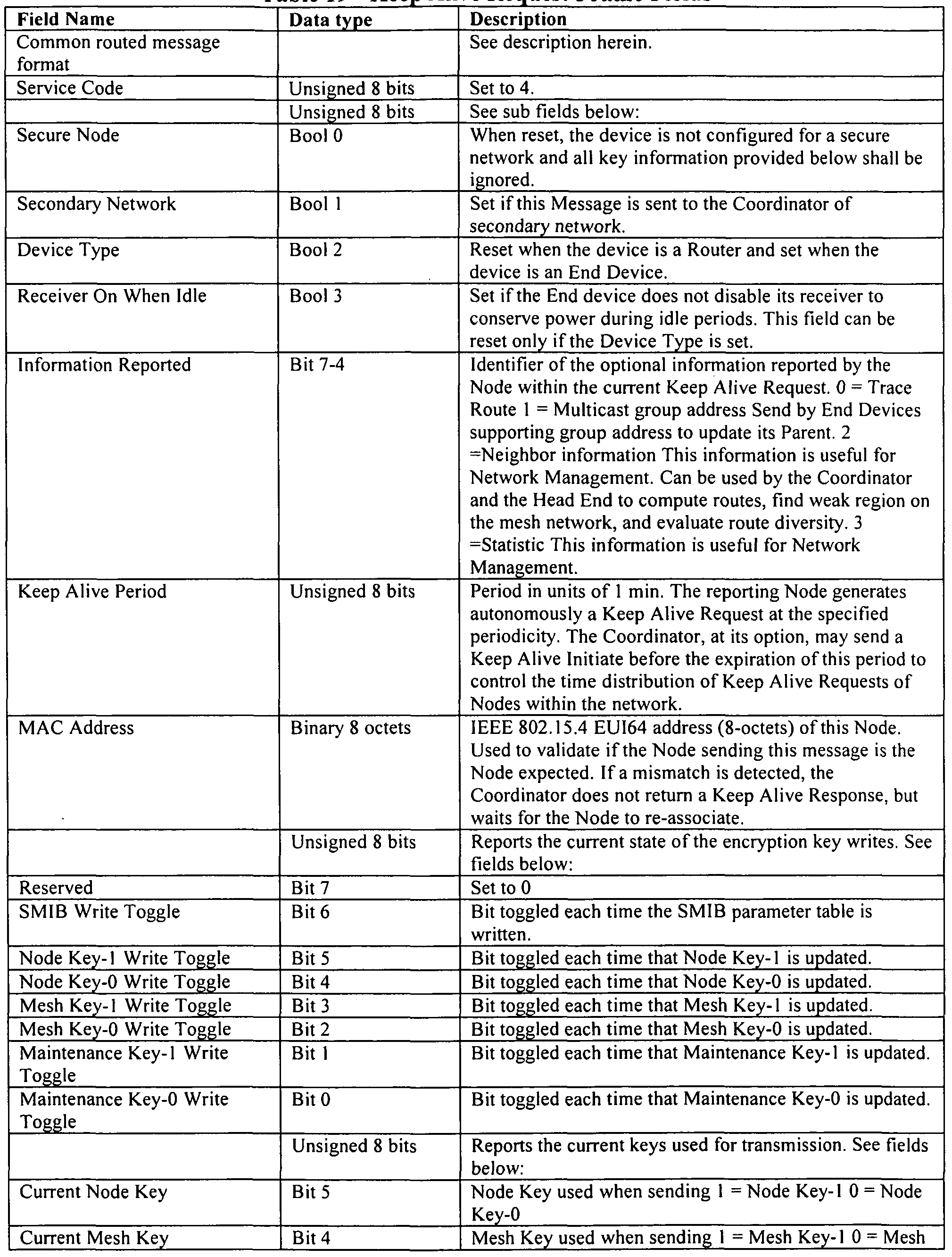

[0260] The following describes the different extensions to this basic frame format.
Transmission of these extensions follows these rules, which are listed in order of priority:
The Trace Route extension is transmitted with the first Keep Alive sent after a Node associates with a Coordinator, and by default when no other extension needs to be transmitted.
The Multicast Group Addresses extension is transmitted by End Devices with the first Keep Alive Response sent after each Parent change.
The Statistics extension is transmitted once a day with the first Keep Alive sent after midnight local time.
The Neighbors extension is transmitted once every 4 hours. [0261] The optional Trace Route extension is shown in Figure 56.
Table 20 - Kee Alive Re uest: Optional Trace Route Frame Fields

[0262] This extension is not authenticated by the Network MIC-32 since the Number of
Hops value is incremented and a PAN identifier and short address is appended at each hop.
[0263] The optional Multicast Group Addresses extension is shown in Figure 57.
Table 21 - Kee Alive Re uest: O tional Multicast Grou Addresses Frame Fields

[0264] The optional Neighbors extension is shown in Figure 58.
Table 22 - Keep Alive Request: O tional Nei hbors Frame Fields

[0265] The optional Statistics extension is shown in Figure 59.
Table 23 - Kee Alive Re uest: O tional Statistics Frame Fields


Table 24 - Statistics Codes


[0266) The Keep Alive Response message is sent by the Coordinator in response to a
Keep Alive Request. The Keep Alive Response frame format is shown in Figure 60.
Table 25 - Keep Alive Res onse Frame Fields

[0267] The Keep Alive Response parameter list member: current time frame format is shown in Figure 61.
Table 26 - Kee Alive Res onse; Parameter list member: Current time Format Fields


[0268] The Keep Alive Response parameter list member: statistics frame format is shown in Figure 62.
Table 27 - Keep Alive Response; Parameter list member: Statistics Format Fields

[0269] The Keep Alive Response parameter list member: SMIB parameter update frame format is shown in Figure 63.
Table 28 - Keep Alive Response: Parameter list member: SMIB parameter update Format
Fields

[0270] The Keep Alive Response parameter list member: Write-Switch-Deactivate Key frame format is shown in Figure 64.
Table 29 - Keep Alive Response: Parameter list member: Write-Switch-Deactivate Key
Format Fields


[0271] Operations on the Mesh Key are associated with the Mesh Key Table entry for the
Coordinator sending the Keep Alive Response message. The Write-Switch-Deactivate Key parameter list member may be occurring multiple times in a message.
[0272] The Route Establishment Request message is used by a Node to request from the
Coordinator a route to a target Node for peer to peer communication using source routing. The Route Establishment Request message frame format is shown in Figure 65.
Table 30 - Route Establishment Re uest Format Fields

[0273] The Route Establishment Response message format shown in Figure 66 is sent by the Coordinator in response to a Route Establishment Request.
Table 31 - Route Establishment Response Format Fields

Table 32 - Power Event Report Frame Fields

[0275] The ping message is used to test mesh communication during quality assessment
(QA) or when the network is deployed. The ping message frame format is shown in Figure 68.
Table 33 - Ping Frame Fields

[0276] The Service Forwarding message is used by the Router servicing a Service
Request to send service messages to and from the Coordinator. The Service Forwarding message frame format is shown in Figure 69.
Table 34 - Service Forwardin Frame Fields


[0277] The Association Request message is sent by a Node to Router in its neighborhood to request an association to the identified mesh network. The Association Request message frame format is shown in Figure 70.
Table 35 - Association Re uest Frame Fields

[0278] An Association Response message is returned by a Router to a Node in response to an Association Request. An Association Response message frame format is shown in Figure 71.
Table 36 - Association Res onse Frame Fields


[0279] The Neighbor Info Request message is broadcast to get information about neighbor Routers. The frame format shown in Figure 72 is used when the originator of the message is not a network member. The frame format shown in Figure 73 is used when the originator of the message is a network member.
Table 37 - Nei hbor Info Re uest Frame Fields

[0280] The Neighbor Info Response message is sent by each neighbor Router when a
Neighbor Info Request is broadcast. This message contains the network name and Coordinator load of the responding neighbor, the quality of the requesting Node's signal as received by this neighbor, and the list tree position of this neighbor on different network trees. The Neighbor Info Response message frame format for an non-network originator is shown in Figure 74. The
Neighbor Info Response message frame format for an in-network originator is shown in Figure 75.
 [0281] The Neighbors Exchange message is broadcast locally by each Node and used to maintain the neighborhood information and to optimize the network tree. The Neighbors Exchange message frame format is shown in Figure 76.
Table 39 - Nei hbors Exchange Frame Fields

[0282] The End Device Data Request message is used by an End Device to request pending data messages from its Parent. The End Device Data Request message frame format is shown in Figure 77.
Table 40 - End Device Data Re uest Frame Fields

[0283] The End Device Data Response message is used in response to an End Device
Request to indicate the presence or not of pending data. The End Device Data Response message frame format is shown in Figure 78.
Table 41 - End Device Data Res onse Frame Fields

[0284] The Service Request message is used by a device non-member of the network to communicate with a specific service such as the commissioning service. The Router used as a proxy is responsible for limiting the flow of messages to provide protection from denial of service attacks. See the Forwarding Service Messages for more detail. The Service Request message frame format is shown in Figure 79. The Service Request Response frame format is shown in Figure 80.
Table 42 - Service Re uest Frame Fields

Table 43 - Common oint to oint messa in Frame Fields

[0286] The Local Data Transfer message is used to transport upper layers information for a point to point communication. The Local Data Transfer message frame format is shown in Figure 82.
Table 44 - Local Data Transfer Frame Fields

[0287] The Frame Reception Rate Test Init messages are used to compute the Frame
Reception Rate. This function is provided mainly in support of radio manufacturing. A test is initiated by sending a Frame Reception Rate Test Init frames, follow by one or a multitude of Frame Reception Rate Test Data frames, followed by an optional Frame Reception Rate Test End frame. The target Node responds to the Frame Reception Rate Test End frame with a Frame Reception Rate Test Result frame. When a Frame Reception Rate Test Result is not received, the originator can retry by sending one or more Frame Reception Rate Test End frames. The Frame Reception Rate Test Init message frame format is shown in Figure 83.
Table 45 - Frame Rece tion Rate Test Init Frame Fields


[0288] The frame format for the Frame Reception Rate Test Data is shown in Figure 84.
Table 46 - Frame Reception Rate Test Data Frame Fields

[0289] The frame format for the Frame Reception Rate Test End is shown in Figure 85.
Table 47 - Frame Rece tion Rate Test End Frame Fields

[0290] The frame format for the Frame Reception Rate Test Result is shown in Figure
86.
Table 48 - Frame Rece tion Rate Test Result Frame Fields

[0291] The Local Broadcast Request message is used to retrieve a list of local devices.
The Local Broadcast Request message frame format is shown in Figure 87.
Table 50 - Local Broadcast Re uest Frame Fields

[0292] The Local Broadcast Response message is sent by all Nodes which have received a Local Broadcast Request with matching criteria (RSSIs and Payload). The Local Broadcast Response message frame format is shown in Figure 88.
Table 51 - Local Broadcast Res onse Frame Fields


[0293] Within the Local Broadcast message is the Payload Content ID 1 which has the frame format shown in Figure 89.
Table 52 - Local Broadcast: Payload Content ID 1 Frame Fields

[0294] Within the Local Broadcast message is the Payload Content ID 2 which has the frame format shown in Figure 90.
Table 53 - Local Broadcast: Payload Content ID 2 Frame Fields

[0295] The End Device Node Present message is sent by a battery operated device, e.g., a sleeping device to a wake-up device, following an impulse, such as a magnetic impulse, from a wake-up device, e.g., hand-held device. The End Device Node Present message frame format is shown in Figure 91.
Table 54 - End Device Node Present Frame Fields


[0296] The Range Test Request message is used to record the signal strength (RSSI) in both directions between two Nodes. The Range Test Request message frame format is shown in Figure 92.
Table 55 - Ran e Test Re uest Frame Fields

[0297] The Range Test Response command is returned in response to the Range Test
Request. The format is shown in Figure 93.
Table 56 - Range Test Response Frame Fields

[0298] The Range Test Initiate command is used to request that a Node initiate a Range
Test Request to a target Node. The Range Test Initiate command frame format is shown in Figure 94.
Table 57 - Ran e Test Initiate Frame Fields


[0299] The Range Test Result command is used in response to a request that a Node initiate the Range Test Request to a target Node. The Range Test Result command frame format is shown in Figure 95.
Table 58 - Range Test Result Frame Fields

[0300] The 802.15.4 standard states the following about Link Quality Indicator ("LQI").
The LQI measurement is a characterization of the strength and/or quality of a received frame. The measurement may be implemented using receiver ED, a signal-to-noise ratio estimation, or a combination of these methods. In a preferred embodiment, transceivers, are used to measure signal strength. The LQI is calculated as follows:

[0301] where / is the received signal level in dB above the sensitivity level of the radio on the meter (node). The sensitivity is measured for each radio model used in the mesh network. It is defined as the signal level above ambient noise for which a frame reception rate of 99% is obtained. Measurement is done with a wired lab setup with frame lengths of 127 octets.
[0302] LQI classes group together links that have similar probability of successful transmission. Various studies on RF propagation, mostly targeting cellular market, suggest using
a fade margin between 20 and 40 dB. Since the meters in the preferred embodiment are fixed and time dependent, attenuation is only caused by the movement of external obstacles (persons, vehicles).
[0303] Accordingly, a margin of 15 dB should be sufficient to have a reliable link. In other words we consider a link with a signal strength 50 dB above the sensitivity level has about the same chances of success as a link with a signal strength 15 dB above sensitivity. The limit for average links is set at 5 dB above sensitivity. Table 59 summarizes the significance of the LQI classes.
Table 59 - L I Class

[0304] The Association Ratio is calculated by a Node to select which Coordinator to choose. It is a weighted sum of: the "Number of Hops" to the Coordinator (from Neighbor Info Response), the "Coordinator Load" (from Neighbor Info Response), the number of local neighbors (from the number of Neighbor Info Responses received for the selected network) and the "Min LQI Class" (maximum value from all Neighbor Info Response adjusted for last hop). Table 60 lists the weighting factors.
Table 60 - Association Ratio Weighting Factors

The formula for the Association Ratio is:
IF Coordinator Load is 100% Ignore this network
IF Coordinator Load < 20%
Association Ratio = COORD_LOAD_WEIGHT ELSE
Association Ratio = COORD_LOAD_WEIGHT * (1 - ((Coordinator Load - 20) / 80))
IF the Dedicated Router Flag of die selected Association Router is true
Association Ratio ÷= HOP_NLM_WEIGHT ELSE
Association Ratio += HOP_NUM_\VEIGHT * (1 -(Number of Hops)/(MAX_HOPS-1))
IF Number of Neighbors >= ASSOCIATION_NEIGHBORS
Association Ratio ÷= NUM_NEIGHBORS_WEIGHT ELSE
Association Ratio += NUM_NEIGHBORS_WEIGHT *
(Number of Neighbors / ASSOCLA.TION_NEIGHBORS)
Association Ratio += LQI_CLASS_WEIGHT * (Mm LQI Class / 3) where
ASSOCIATION_NEIGHBORS = 5
[0305] The Preferred Route Ratio is computed by a Node to select within its Parents, the one that represents the optimized path to access the Coordinator. This ratio is calculated based on the neighborhood table information as received within a Neighbor Info Response or a Neighbors Exchange.
Preferred Route Ratio = Min LQI class « 12 | (15 - Number of Hops) « 8 | Avg LQI [0306] The preferred Router, based on this ratio, will correspond to:
For all the possible routes with the best min LQI class, select the routes with the least number of hops
From this remaining list, select the one with the best Avg LQI (not used to change the preferred routers)
[0307] End Devices selects a neighboring Router based on the following criteria applied in the order indicated:
From the list of neighbors with the best LQI class (Class computed only on the link between the RFD and its neighbor) select the Routers with the lowest "Router load"
From the remaining list, select a Router with the least number of hops From the remaining list, select the Routers with the best avg LQI
[0308] The pseudo-random delays required by Nodes for this layer are computed based on the following equation:
pseudoRandomNumber = ((shortAddress & 0x7F) « 6) XOR ((longAddress » i) & OxTF) XOR ((pseudoRandomVahie » i) & OxTF) pseudoRandomPeriod (sec) = pseudoRandomNumber * period/ 8191 Each time a pseudo-random number is generated, i = ((i+1) % 8)
[0309] The pseudoRandom Value represents a value within the radio which changes over time, such as the Neighbor table checksum or the "Number of frames transmitted" statistic.
[0310] For example: lόbitsAddress = 35 = 0100011 longAddress = 948347 = 1110011110000111101 1 pseudoRandomValue = 3384854 = 1100111010011000010110 period = 20 s lth pseudoRandom period = (0100011 « 6) xor 1111011 xor 0010110
= 0100010101101 = 2221 • 20 / 8191 = 5,423 s 2td pseudoRandom period = (0100011 « 6) xor 01 11101 xor 0001011
= 0100011110110 = 2294 * 20 / 8191 = 5,601 s 3lt pseudoRandom period = (0100011 « 6) xor 0011110 xor 0000101
= 0100011011011 = 2267 * 20 / 8191 = 5=535 s 4ώ pseudoRandom period = (0100011 « 6) xor 0001111 xor 1000010
= 0100010001101 = 2189 * 20 / 8191 = 5:344 s
[0311] The IEEE 802.15.4 short addresses are assigned sequentially by the coordinator.
Six bits of this address are used to partition Nodes into 64 different groups. This number represents bits 8 to 13 of the final pseudo-random number. For example, if a network has 432 Nodes, between 6 and 7 End points will share the same 6 bits. Bit 0 to 7 of the pseudo-random number is computed based on the IEEE 802.15.4 long address and a pseudo-random value that changes over time.
[0312] The pseudo-random number generated is a number between 0 and 8191 , which needs to be scaled for the appropriate range.
[0313] The following tables propose data structure definitions in support of the implementation of the SM layer discussed herein and may be adapted for each specific implementation.
Table 61 - Global Variables

[0314] The Mesh Key Tables stores the Mesh Key(s) used by the device. Each Mesh Key is associated with the PAN ID of the Coordinator it is used with. Mesh Keys are administered by the associated Coordinator.
Table 62a - Mesh Key Table


[0315] The Node Key table stores the Node Key(s) used by the device. The SM network security process uses the Node Key Table to look up the information needed for the Network Security MIC calculation for messages between the Coordinator and devices. The information in the Node Key Table is retained during a power outage and a device reset.
Table 63 - Node Key Table

Table 64 - Maintenance Ke Table

[0317] The Neighborhood Table data structure is maintained in each radio to keep the information about neighbor Nodes. This data structure is required to implement at least the following processes: Association, Tree Routing, Route Discovery, Neighbors Exchange, Tree Optimization, Checkpoint.
Table 65a - Nei hborhood Table

Table 65b - Nei hborhood Table Entries


[0318] When the number of Neighbors exceeds the capacity of the Neighborhood table, the goal is to keep in the table 5 best Parents/Siblings (best routes) and all nodes that set the current node as preferred Parent (avoid tree instability). We also want to give a chance to new candidates to flag the current Node as preferred Parent. This is done by including them in a round robin fashion among others entry. The radio applies the following logic when it receives a new candidate.
[0319] If the new candidate is a not a parent, replace the next entry that: is not one of the 5 best Parents/Siblings
has not select the current Node as preferred parent was sent at least once in a Neighbor Exchange message.
[0320] This last clause (3) allows candidates to receive the information needed to choose this node as preferred Parent. If the new candidate has flagged the current node as preferred Parent, this last condition is ignored.
[0321] If the new candidate is a Parent/Sibling:
If we have less than 5 best Parents/Sibling, use the same scheme as if it was not a parent. In last resort, replace a node that set the current Node as preferred parent using the same round robin scheme.
If we have already 5 best Parents/Sibling, replace the worst Parent/Sibling if the candidate's preferred route ratio is greater than its preferred route ratio.
[0322] The Routing table is used to maintain routes established using the Route
Discovery process.

[0323] Freshness rules for each time the table is accessed:
If entry = new new entry Freshness = OxFF For each other entry
If entry Freshness = 0, entry Freshness = 0 Else entry Freshness = Freshness -1 Else
TempJFreshness = access entry Freshness accessed entry Freshness = OxFF For each other entry
If entry Freshness = 0 entry Freshness = 0 Else
If entry Freshness > TempJFreshness entry Freshness = Freshness -1 Else entry Freshness = Freshness
[0324] Freshness Use: The Freshness value is used when the table is full and a new entry is added. The entry with the smallest Freshness value is replaced with the new entry. If more than one entry has a value of zero, anyone can be replaced. This case only occurs if the table size is greater than 255 entries.
[0325] Every time a mesh frame is forwarded, no matter the routing method used, at the exception of the Keep Alive Initiate, the forwarding Node creates a temporary route entry to the originator in Temporary Route Take. This allows the destination Node to quickly send a reply, even if it didn't previously know the route to the originator Node. This route expires after TEMP_ROUTE_TO.
Table 67a - Tem orar Route Table

Child.
Table 68a - End Device Table

J0327] Security events are provided to the upper layers for diagnostic and auditing purposes. The content of each event is described bellow.
Table 69 - Security Events

Discovery process with the Trace Route flag bit set and through the Route Establishment process.
Table 70a - Source Route Table

Table 70b - Source Route Table Entr

[0329] Finally, the SMIB table of parameters is set forth below.
Table 71 - SM Information Base (SMIB) Table


Claims
1. A method of associating a device to a mesh network, comprising: selecting a network for association including: requesting, by the device, neighbor information from neighboring devices which may belong to one or more networks, receiving, at the device from one or more neighboring devices, neighbor information for each of the one or more neighboring devices, applying an association ratio algorithm to the received neighbor information to determine which of the one or more networks to select for association; selecting a router within the selected network through which to proxy messages by applying a preferred route ratio algorithm; sending a network association request from the device through the router to a network coordinator; at the network coordinator, performing one of the following in response to the network association request: validating the association request with an association response message which includes a short address for the device, not responding to the network association request; and constructing, at the device, an initial neighborhood table.
2. A process for routing data frames from a first node to a second node within a network, the process including: a tree routing sub-process, a source routing sub-process, a temporary routing sub- process and a mesh routing sub-process, wherein the particular sub-process for routing a data frame from the first node the second nodes is selected in accordance with the following logic executed on a processor: if the data frame has a source route header the source routing sub-process is selected; if there is an entry for the target address in a temporary routing table, the temporary routing sub-process is selected; if the second node is a coordinator node, the tree routing sub-process is selected; if the second node is not a coordinator node, the mesh routing sub-process is selected.
3. The process according to claim 2, wherein the tree routing sub-process comprises: accessing by the first node a neighborhood table to determine a route to the coordinator; selecting by the first node a neighbor with a preferred parent flag; transmitting the data frame to a first parent neighbor with the preferred parent flag; if transmission to the first parent neighbor does not succeed, selecting a next parent neighbor from the neighborhood table with a hop-count value less then the hop-count value of the first node until the transmission succeeds; if transmission does not succeed via a neighbor having a hop-count value less then the hop-count value of the first node, selecting a sibling neighbor from the neighborhood table for transmission to the second node, wherein a sibling neighbor has a hop-count value that is equal to the hop-count value of the first node. N
4. The process according to claim 3, wherein the tree routing sub-process further comprises within the step of selecting a next parent neighbor from the neighborhood table with a hop-count value less than the hop-count value of the first node until the transmission succeeds: ordering next parent neighbors according to a preferred route ratio value as follows:
Preferred Route Ratio = Min LQI class « 12 | (15 - Number of Hops) « 8 | Avg LQI where Min LQI class is the minimum of all LQI class for each hop between the first node and the coordinator node through this next parent neighbor, and
Avg LQI is the average of the LQI value of each hop between the first node and the coordinator node through this next parent neighbor; for all the possible routes with the best min LQI class, selecting the next parent neighbors with the least number of hops; and select the next parent neighbor with the best Avg LQI.
5. The process according to claim 2, wherein the source routing sub-process comprises: following a known route from the first node to the second node, the known route being embedded in a header of the data frame in the form of a list of node addresses located along the known route from the first node to the second node, wherein each node located along a route path from the first node to the second node forwards the data frame to the next node address located on the list after the current node's address; wherein the known route to the second node is determined by
(i) sending by the first node a route request frame to the second node with a trace route flag set or
(ii) sending by the first node a route establishment request frame to the coordinator requesting a route to the second node.
6. The process according to claim 2, wherein the mesh routing sub-process comprises: accessing a first route table at the first node to determine a route for the second node based on the second node address; sending the data frame from the first node to an interim node in the route using the interim node address from the route; accessing a second route table at the interim node to determine a second interim node address from the route based on the second node address; sending the data frame from the interim node to a second interim node address; if the interim node is unable to send the data frame to the second interim node address, broadcasting a route error message and deleting a second interim node address; and receiving an error message at the first node if the data frame does not reach the second node.
7. A process for discovering a route from a first node to a second node in a mesh network comprising: broadcasting by the first node a route request message that is propagated across multiple nodes within the mesh network in accordance with the following process implemented within processors at the multiple nodes: accepting a route request at a receiving node if:
(i) no previous received route request message had the same request ID; and
(ii) the route request message is received through a link with a minimum LQI class at least equal to the requested one; identifying the receiving node as a route candidate and
(iii) if the route request message is accepted by an intermediate node, re- broadcasting the route request;
(iv) if the route request message is accepted by the second node, sending a route reply message from the second node through the identified route candidate back to the first node to establish a static bidirectional route within the mesh network between the first node and the second node.
8. A process for upgrading a route from a first node to a second node in a mesh network further comprising: accepting a route request at a receiving node for upgrading the route if: a route candidate already exists for the request ID; the request was received through a link with a minimum LQI class at least equal to the requested one; and the request was received through a better link than the prior received one, as determined by one of the following sets of conditions:
(i) the receiving node is a neighbor, the route request is received from a neighbor and a resulting route length is shorter;
(ii) the receiving node is not a neighbor, the route request is received from a neighbor and a resulting route length is shorter or equal to existing route length;
(iii) the receiving node is not a neighbor, the route request is received from a non-neighbor and a resulting route length is shorter; otherwise rejecting the route request.
9. A process for requesting a route from a first node to a second node within a mesh network comprising: transmitting a route request message to a pre-determined coordinator node, wherein the route request message includes a long address for the second node; constructing at the coordinator node a route through one or more routing nodes from the first node to the second node; transmitting a response to the route request message to the first node including the route to the second node, wherein the route includes an assigned short address for the second node.
10. The process according to claim 9, wherein the long address is 8 octets and the short address is 2 octets.
1 1. A data structure for securing data frames transmitted in a single hop within a mesh network from a first node to a second node, the data structure comprising: a data link layer (DLL) security header located after a service-type octet when a predetermined security header flag is selected within the service-type octet, the DLL security header including: a first set of bits containing a portion of a transmitted nonce count; a bit following the first set of bits containing a key identifier (ID), wherein the key ID selects a current version of a key used for calculating a message integrity check (MIC); and a second set of bits containing the MIC.
12. The data structure according to claim 1 1 , wherein a DLL nonce used in the MIC calculation includes: a thirteen octet nonce composed of the full DLL nonce count and the MAC layer source address, wherein the Full DLL Nonce Count is five octets long as the MAC layer source address is selected from the group consisting of (i) an 8-octet long extended unique identifier (EUI) address, and (ii) a 2-octet source PAN ID and a 2-octet short address prefixed by four octets of all ones.
13. A process for validating integrity of message data transmitted in a single hop from a first node to a second node within a mesh network, the process comprising: checking at a processor of the second node the 23 least significant bits (0-22) of a count transmitted from the first node against a last authenticated count; if the transmitted count value is greater than the last authenticated count, combining at a processor of the second node, the 23 least significant bits (0-22) with the 17 most significant bits (23 - 39) of the last authenticated count to form a revised count; if the transmitted count value is lower than the last authenticated count, incrementing the value of bits 23 through 29 by one before combining at a processor of the second node, the 23 least significant bits (0-22) with the 17 most significant bits (23 - 39) of the last authenticated count to form a revised count; calculating at the processor of the second node a message integrity check (MIC) value using the revised count and pre-selected key; if the calculated MIC value equals a received MIC value, then the message data integrity is validated.
14. A data structure for securing data frames transmitted in multiple hops using multiple nodes across a mesh network, the data structure comprising: a network security header located after a data link layer (DLL) security layer within a mesh header, the network security header including: a first set of bits containing a network count; a bit following the first set of bits containing a network key identifier (ID); and a second set of bits containing a network message integrity check (MIC).
15. The data structure according to claim 14, wherein a network security nonce for MIC calculation is thirteen octets and when the data frame is a request includes a network count, an originator PAN ID and an address padded with zeros and when the message is a response includes the network count, target PAN ID, target address, originator PAN ID and originator address.
16. A process for validating integrity of a data frame transmitted in multiple hops using multiple nodes across a mesh network, the process comprising: receiving a data frame at a receiver node, wherein the data frame includes a network security header including a network count, a network key identifier (ID) and a message integrity check (MIC); processing an identifier (ID) for an originating node that originated the data frame and a source field address to determine if the data frame was received from a coordinator node or a non-coordinator node; if the data frame was received from a coordinator node, the network key ID selects a node key for determining verification; if the data frame was received from a non-coordinator node, the network key ID selects a mesh key for determining verification; when the received data frame is a request, a nonce is a combination of at least the network count, the originating node ID and an originating node address and the receiving node verifies the integrity of the frame by: adding a 0 to the network field to make a 40 bit field, calculating the received MIC using either the node key or the mesh key as identified by the network key ID; comparing the transmitted MIC with the received MIC, wherein the data frame is verified if the transmitted MIC is equal to the received MIC; when the received data frame is a response, the network count is combined with the identifier and address for the target of the data frame and the originating node ID and an originating node address and the receiving node compares a network count in the response with a network count in the request, wherein the data frame is verified if the response network count is equal to the request network count.
Priority Applications (2)
| Application Number | Priority Date | Filing Date | Title |
|---|---|---|---|
| EP09811849.0A EP2321983B1 (en) | 2008-09-04 | 2009-09-04 | Method for implementing mesh network communications using a mesh network protocol |
| CA2734953A CA2734953A1 (en) | 2008-09-04 | 2009-09-04 | A system and method for implementing mesh network communications using a mesh network protocol |
Applications Claiming Priority (2)
| Application Number | Priority Date | Filing Date | Title |
|---|---|---|---|
| US9411608P | 2008-09-04 | 2008-09-04 | |
| US61/094,116 | 2008-09-04 |
Publications (1)
| Publication Number | Publication Date |
|---|---|
| WO2010027495A1 true WO2010027495A1 (en) | 2010-03-11 |
Family
ID=41797385
Family Applications (1)
| Application Number | Title | Priority Date | Filing Date |
|---|---|---|---|
| PCT/US2009/005008 WO2010027495A1 (en) | 2008-09-04 | 2009-09-04 | A system and method for implementing mesh network communications using a mesh network protocol |
Country Status (4)
| Country | Link |
|---|---|
| US (3) | US8699377B2 (en) |
| EP (1) | EP2321983B1 (en) |
| CA (1) | CA2734953A1 (en) |
| WO (1) | WO2010027495A1 (en) |
Cited By (8)
| Publication number | Priority date | Publication date | Assignee | Title |
|---|---|---|---|---|
| WO2013128317A1 (en) * | 2012-03-01 | 2013-09-06 | Nds Limited | Anti-replay counter measures |
| CN103974202A (en) * | 2014-05-28 | 2014-08-06 | 苏州鸣伦电子科技有限公司 | Multicast-tree-based code dispatching method for power demand side acquisition node |
| CN105451158A (en) * | 2014-09-19 | 2016-03-30 | 美国博通公司 | Bluetooth low energy automation mesh network |
| WO2016073818A1 (en) * | 2014-11-07 | 2016-05-12 | Cisco Technology, Inc. | Phased network formation for power restoration |
| EP2660564B1 (en) | 2012-05-04 | 2017-01-11 | Itron, Inc. | Verification of connection of meters to network |
| EP3203689A1 (en) * | 2011-10-18 | 2017-08-09 | Itron Global SARL | Peer-to-peer communications in ami with source-tree routing |
| CN111757413A (en) * | 2020-06-12 | 2020-10-09 | 安凯(广州)微电子技术有限公司 | Broadcast and route hybrid transmission method and system in wireless Mesh network |
| EP3965400A1 (en) * | 2020-09-08 | 2022-03-09 | Thales Alenia Space Deutschland GmbH | Method for data transmission in an ad hoc network |
Families Citing this family (166)
| Publication number | Priority date | Publication date | Assignee | Title |
|---|---|---|---|---|
| KR101144243B1 (en) * | 2005-03-10 | 2012-05-14 | 톰슨 라이센싱 | Hybrid mesh routing protocol |
| KR101225274B1 (en) * | 2005-11-09 | 2013-01-22 | 톰슨 라이센싱 | Route selection in wireless networks |
| US7844212B1 (en) * | 2007-10-03 | 2010-11-30 | Alec Woo | System and method for reliably communicating information without explicit acknowledgements |
| US8112694B1 (en) | 2007-10-03 | 2012-02-07 | Cisco Technology, Inc. | System and method for reliably communicating information without explicit acknowledgements including retransmission of older, missed commands |
| EP2203911A4 (en) | 2007-10-25 | 2011-12-28 | Trilliant Networks Inc | Gas meter having ultra-sensitive magnetic material retrofitted onto meter dial and method for performing meter retrofit |
| WO2009067256A2 (en) | 2007-11-25 | 2009-05-28 | Trilliant Networks, Inc. | System and method for power outage and restoration notification in an advanced metering infrastructure network |
| WO2009067259A1 (en) * | 2007-11-25 | 2009-05-28 | Trilliant Networks, Inc. | Transport layer and model for an advanced metering infrastructure (ami) network |
| WO2009067261A1 (en) * | 2007-11-25 | 2009-05-28 | Trilliant Networks, Inc. | System and method for transmitting and receiving information on a neighborhood area network |
| EP2215550A1 (en) | 2007-11-25 | 2010-08-11 | Trilliant Networks, Inc. | Energy use control system and method |
| US20090138866A1 (en) * | 2007-11-25 | 2009-05-28 | Michel Veillette | Upgrade process system and method |
| US8054769B2 (en) * | 2009-02-22 | 2011-11-08 | Chung-Shan Institute of Science and Technology Armaments Bureau, Ministry of National Defense | Wireless sensing control network system and operating method thereof |
| US8542620B2 (en) | 2009-05-05 | 2013-09-24 | Qualcomm Incorporated | Dynamic energy saving mechanism for access points |
| CN102111306B (en) * | 2009-12-23 | 2013-06-26 | 杭州华三通信技术有限公司 | Method, system and device for detecting virtual link faults based on fiber channel over Ethernet (FCoE) |
| JP5589410B2 (en) * | 2010-01-29 | 2014-09-17 | 沖電気工業株式会社 | Communication system and communication apparatus |
| US8537733B1 (en) | 2010-02-12 | 2013-09-17 | Qualcomm Incorporated | Dynamic power mode switch in a wireless ad-hoc system |
| KR101764888B1 (en) * | 2010-02-16 | 2017-08-16 | 한국전자통신연구원 | Apparatus and method for wideband high frequency short-range wireless communication |
| US9311446B1 (en) * | 2010-03-19 | 2016-04-12 | Qualcomm Incorporated | Multicast transmission for power management in an ad-hoc wireless system |
| US8588156B1 (en) | 2010-04-27 | 2013-11-19 | Qualcomm Incorporated | Direct data communication in infrastructure mode in wireless communication systems |
| US9635693B2 (en) * | 2010-05-07 | 2017-04-25 | Samsung Electronics Co., Ltd. | Method of performing pairing between coordinator and device in network, method of performing pairing between devices, method of pairing between coordinators and network system including the coordinators and the devices |
| CA2809034A1 (en) | 2010-08-27 | 2012-03-01 | Randy Frei | System and method for interference free operation of co-located tranceivers |
| CA2813958A1 (en) * | 2010-10-05 | 2012-04-12 | Utc Fire & Security Corporation | Bi-directional link margin establishment for wireless embedded systems |
| US9088948B2 (en) * | 2010-10-27 | 2015-07-21 | Silicon Laboratories Inc. | Reduced power consumption in a wireless network device |
| US8832428B2 (en) | 2010-11-15 | 2014-09-09 | Trilliant Holdings Inc. | System and method for securely communicating across multiple networks using a single radio |
| KR101217798B1 (en) * | 2010-12-07 | 2013-01-02 | 금오공과대학교 산학협력단 | An efficient routing system basee on link quality and load balancing for wireless sensor networks |
| US20120147800A1 (en) * | 2010-12-10 | 2012-06-14 | Minyoung Park | Power management in a wireless network having stations with different power capabilities |
| KR20120067883A (en) * | 2010-12-16 | 2012-06-26 | 한국전자통신연구원 | A multi hop routing apparatus and a multi hop routing method |
| US8503309B2 (en) * | 2010-12-17 | 2013-08-06 | Cisco Technology, Inc. | Dynamic expelling of child nodes in directed acyclic graphs in a computer network |
| US9282383B2 (en) | 2011-01-14 | 2016-03-08 | Trilliant Incorporated | Process, device and system for volt/VAR optimization |
| WO2012103072A2 (en) * | 2011-01-25 | 2012-08-02 | Trilliant Holdings, Inc. | Aggregated real-time power outages/restoration reporting (rtpor) in a secure mesh network |
| KR20120087635A (en) * | 2011-01-28 | 2012-08-07 | 삼성전자주식회사 | Method and apparatus for remotely controlling consumer electronics device using wireless personal area network proxy |
| EP3285459B1 (en) | 2011-02-10 | 2022-10-26 | Trilliant Holdings, Inc. | Device and method for coordinating firmware updates |
| US9041349B2 (en) | 2011-03-08 | 2015-05-26 | Trilliant Networks, Inc. | System and method for managing load distribution across a power grid |
| WO2012127095A1 (en) * | 2011-03-18 | 2012-09-27 | Nokia Corporation | Non-networked wireless communication |
| US8902894B2 (en) * | 2011-05-06 | 2014-12-02 | Qualcomm Incorporated | Apparatus and methods for wireless communication using a packet structure that indicates whether payload length field and payload are included in the packet |
| CN102186261B (en) * | 2011-05-30 | 2014-08-20 | 杭州华三通信技术有限公司 | Implementation method and device for IPv6 (Internet Protocol Version 6) neighbor discovery protocol in WLAN (Wireless Local Area Network) |
| US9306833B2 (en) * | 2011-06-20 | 2016-04-05 | Cisco Technology, Inc. | Data routing for power outage management |
| US8553536B2 (en) * | 2011-07-12 | 2013-10-08 | General Electric Company | Mesh network management system |
| GB201113136D0 (en) * | 2011-07-29 | 2011-09-14 | Texecom Ltd | A method for improving performance and reducing power consumption of a wireless network arrangement |
| TWI444078B (en) * | 2011-08-12 | 2014-07-01 | Nat Univ Tsing Hua | Realization of sleep and reconnecting functions on network system and the method |
| US9082294B2 (en) * | 2011-09-14 | 2015-07-14 | Enernoc, Inc. | Apparatus and method for receiving and transporting real time energy data |
| US9001787B1 (en) | 2011-09-20 | 2015-04-07 | Trilliant Networks Inc. | System and method for implementing handover of a hybrid communications module |
| US20130086635A1 (en) * | 2011-09-30 | 2013-04-04 | General Electric Company | System and method for communication in a network |
| US20130083660A1 (en) | 2011-10-03 | 2013-04-04 | Cisco Technology, Inc. | Per-Group ECMP for Multidestination Traffic in DCE/TRILL Networks |
| US9225660B2 (en) | 2011-12-21 | 2015-12-29 | Arm Finland Oy | Method, apparatus and system for addressing resources |
| US10374976B2 (en) | 2011-12-21 | 2019-08-06 | Arm Finland Oy | Method, apparatus and system for addressing resources |
| US9094364B2 (en) * | 2011-12-23 | 2015-07-28 | A10 Networks, Inc. | Methods to manage services over a service gateway |
| US9066287B2 (en) | 2012-01-24 | 2015-06-23 | Qualcomm Incorporated | Systems and methods of relay selection and setup |
| US9537763B2 (en) * | 2012-03-02 | 2017-01-03 | Nec Corporation | Communication system, control apparatus, control method and program |
| WO2013129671A1 (en) * | 2012-03-02 | 2013-09-06 | 富士通株式会社 | Ad hoc network system, and route selection method |
| US9049658B2 (en) | 2012-03-06 | 2015-06-02 | Qualcomm Incorporated | Power save mechanism for peer-to-peer communication networks |
| US9515920B2 (en) * | 2012-04-20 | 2016-12-06 | Futurewei Technologies, Inc. | Name-based neighbor discovery and multi-hop service discovery in information-centric networks |
| US20130286909A1 (en) * | 2012-04-26 | 2013-10-31 | Qualcomm Atheros, Inc. | System and method for reducing power consumption in a wireless communication system |
| US10455071B2 (en) | 2012-05-09 | 2019-10-22 | Sprint Communications Company L.P. | Self-identification of brand and branded firmware installation in a generic electronic device |
| US9860785B2 (en) * | 2012-05-11 | 2018-01-02 | Qualcomm, Incorporated | Apparatus and methods for control frame and management frame compression |
| US9191886B2 (en) * | 2012-06-01 | 2015-11-17 | Crestron Electronics Inc. | Commissioning of wireless devices in personal area networks |
| US9794796B2 (en) | 2012-06-13 | 2017-10-17 | Qualcomm, Incorporation | Systems and methods for simplified store and forward relays |
| US9510271B2 (en) * | 2012-08-30 | 2016-11-29 | Qualcomm Incorporated | Systems, apparatus, and methods for address format detection |
| CN104737589A (en) * | 2012-11-06 | 2015-06-24 | 富士通株式会社 | Network device and transmission program |
| US9197541B2 (en) * | 2012-11-15 | 2015-11-24 | Compass Electro Optical Systems Ltd. | Router with passive interconnect and distributed switchless switching |
| US9319310B2 (en) * | 2012-11-15 | 2016-04-19 | Compass Electro Optical Systems Ltd. | Distributed switchless interconnect |
| US9832035B2 (en) * | 2012-11-19 | 2017-11-28 | Arris Enterprises Llc | Power saving mode for network devices |
| US9654604B2 (en) | 2012-11-22 | 2017-05-16 | Intel Corporation | Apparatus, system and method of controlling data flow over a communication network using a transfer response |
| US9264103B2 (en) * | 2012-12-17 | 2016-02-16 | Texas Instruments Incorporated | Asymmetric channels in power line communications |
| US9251253B2 (en) | 2013-01-05 | 2016-02-02 | Qualcomm Incorporated | Expeditious citation indexing |
| JP6007799B2 (en) * | 2013-01-16 | 2016-10-12 | 富士通株式会社 | Centralized network control system |
| US9549009B1 (en) | 2013-02-08 | 2017-01-17 | Sprint Communications Company L.P. | Electronic fixed brand labeling |
| US10355962B2 (en) * | 2013-02-11 | 2019-07-16 | Riverbed Technology, Inc. | Network topology generation using traceroute data |
| KR102023402B1 (en) * | 2013-02-28 | 2019-09-23 | 삼성전자주식회사 | Method and apparatus for monitoring internet connection status in communication system |
| US9614935B2 (en) * | 2013-03-15 | 2017-04-04 | Qualcomm Incorporated | Protected control frames |
| ITTO20130297A1 (en) * | 2013-04-12 | 2014-10-13 | Selex Es Spa | METHOD OF COMMUNICATION OF SMF FOR A MANET NETWORK, AND NETWORK AND MOBILE NETWORK KNOT THAT IMPLEMENT THIS COMMUNICATION METHOD |
| JP6225249B2 (en) * | 2013-06-08 | 2017-11-01 | 華為技術有限公司Huawei Technologies Co.,Ltd. | Routing and forwarding method, apparatus and system |
| US9532211B1 (en) | 2013-08-15 | 2016-12-27 | Sprint Communications Company L.P. | Directing server connection based on location identifier |
| US9161209B1 (en) * | 2013-08-21 | 2015-10-13 | Sprint Communications Company L.P. | Multi-step mobile device initiation with intermediate partial reset |
| US10506398B2 (en) | 2013-10-23 | 2019-12-10 | Sprint Communications Company Lp. | Implementation of remotely hosted branding content and customizations |
| US9743271B2 (en) | 2013-10-23 | 2017-08-22 | Sprint Communications Company L.P. | Delivery of branding content and customizations to a mobile communication device |
| US20150120863A1 (en) * | 2013-10-25 | 2015-04-30 | Qualcomm Incorporated | Proxy network device selection in a communication network |
| US9743458B2 (en) * | 2013-11-06 | 2017-08-22 | Google Technology Holdings LLC | Adaptive crowdsourced keep-alive interval determination |
| US9603009B1 (en) | 2014-01-24 | 2017-03-21 | Sprint Communications Company L.P. | System and method of branding a device independent of device activation |
| GB2512749B (en) * | 2014-02-25 | 2015-04-01 | Cambridge Silicon Radio Ltd | Linking ad hoc networks |
| US9548918B2 (en) * | 2014-02-28 | 2017-01-17 | General Electric Company | Edge router systems and methods |
| WO2015130752A1 (en) * | 2014-02-28 | 2015-09-03 | John Boudreaux | Sensor network gateway |
| US10379873B2 (en) | 2014-02-28 | 2019-08-13 | Tyco Fire & Security Gmbh | Distributed processing system |
| US10152864B2 (en) | 2014-02-28 | 2018-12-11 | Tyco Fire & Security Gmbh | Distributed rules engines for robust sensor networks |
| US9717047B2 (en) | 2014-03-07 | 2017-07-25 | Qualcomm Incorporated | Fairness-based message transmission in a wireless network |
| WO2015139026A2 (en) | 2014-03-14 | 2015-09-17 | Go Tenna Inc. | System and method for digital communication between computing devices |
| US9602394B2 (en) * | 2014-03-20 | 2017-03-21 | Texas Instruments Incorporated | Routing frame propagation in power line networks |
| WO2015146066A1 (en) * | 2014-03-28 | 2015-10-01 | 日本電気株式会社 | Wireless terminal, metering device, and communication control method |
| US9681251B1 (en) | 2014-03-31 | 2017-06-13 | Sprint Communications Company L.P. | Customization for preloaded applications |
| US9380513B2 (en) | 2014-05-16 | 2016-06-28 | Qualcomm Incorporated | Reducing broadcast duplication in hybrid wireless mesh protocol routing |
| US9392525B2 (en) | 2014-05-16 | 2016-07-12 | Qualcomm Incorporated | Establishing reliable routes without expensive mesh peering |
| US10504148B2 (en) | 2014-05-23 | 2019-12-10 | Qualcomm Incorporated | Peer-to-peer relaying of discovery information |
| US10142847B2 (en) * | 2014-05-23 | 2018-11-27 | Qualcomm Incorporated | Secure relay of discovery information in wireless networks |
| US9426641B1 (en) | 2014-06-05 | 2016-08-23 | Sprint Communications Company L.P. | Multiple carrier partition dynamic access on a mobile device |
| EP3123667B1 (en) * | 2014-06-26 | 2020-08-05 | NEC Corporation | Method for monitoring a status in form of presence and/or absence of a network entity |
| US9614770B2 (en) * | 2014-07-21 | 2017-04-04 | Cisco Technology, Inc. | Network traffic control during limited power situations |
| WO2016039507A1 (en) * | 2014-09-11 | 2016-03-17 | 이화여자대학교 산학협력단 | Position determination method for sensor arrangement based on wireless communications in building and position determination system for sensor arrangement based on wireless communications in building |
| US9992326B1 (en) | 2014-10-31 | 2018-06-05 | Sprint Communications Company L.P. | Out of the box experience (OOBE) country choice using Wi-Fi layer transmission |
| US9588928B1 (en) * | 2014-11-02 | 2017-03-07 | Netronome Systems, Inc. | Unique packet multicast packet ready command |
| US9727513B1 (en) * | 2014-11-02 | 2017-08-08 | Netronome Systems, Inc. | Unicast packet ready command |
| US9727512B1 (en) * | 2014-11-02 | 2017-08-08 | Netronome Systems, Inc. | Identical packet multicast packet ready command |
| DE102014222662A1 (en) * | 2014-11-06 | 2016-05-12 | Siemens Ag Österreich | Method for data enrichment of measurement data records of a low-voltage network |
| US20160150459A1 (en) * | 2014-11-19 | 2016-05-26 | Qualcomm Incorporated | Techniques to support heterogeneous network data path discovery |
| US20160182252A1 (en) * | 2014-12-22 | 2016-06-23 | Greenvity Communications, Inc. | Wireless and Powerline Communication Mesh Network |
| US9280389B1 (en) | 2014-12-30 | 2016-03-08 | Tyco Fire & Security Gmbh | Preemptive operating system without context switching |
| US9398462B1 (en) | 2015-03-04 | 2016-07-19 | Sprint Communications Company L.P. | Network access tiered based on application launcher installation |
| KR102281737B1 (en) * | 2015-03-16 | 2021-07-26 | 한국전자통신연구원 | Apparatus and Method for Running Dynamically Packet Relay in Sensor Network |
| US10979894B2 (en) * | 2015-04-30 | 2021-04-13 | Lg Electronics Inc. | Method and device for allocating address of device in Bluetooth mesh network |
| WO2016191197A1 (en) * | 2015-05-22 | 2016-12-01 | Linear Technology Corporation | Low power sensor node operation for wireless network |
| US20170048310A1 (en) * | 2015-08-14 | 2017-02-16 | Google Inc. | Peer-to-peer enabled activation |
| US10637765B2 (en) * | 2015-09-24 | 2020-04-28 | At&T Intellectual Property I, L.P. | Management of forwarding tables at edge routers |
| US10505948B2 (en) * | 2015-11-05 | 2019-12-10 | Trilliant Networks, Inc. | Method and apparatus for secure aggregated event reporting |
| US9954777B2 (en) * | 2016-01-14 | 2018-04-24 | International Business Machines Corporation | Data processing |
| EP3409071B1 (en) * | 2016-01-28 | 2021-11-10 | Hewlett Packard Enterprise Development LP | Wireless mesh network formation |
| JP2017152855A (en) * | 2016-02-23 | 2017-08-31 | 株式会社東芝 | Radio communication device, radio communication method, and program |
| US10841222B2 (en) * | 2016-07-05 | 2020-11-17 | Ologn Technologies Ag | Systems, apparatuses and methods for network packet management |
| US11570098B2 (en) | 2016-07-05 | 2023-01-31 | Six Impossible Things Before Breakfast Limited | Systems, apparatuses and methods for cooperating routers |
| US9992097B2 (en) * | 2016-07-11 | 2018-06-05 | Cisco Technology, Inc. | System and method for piggybacking routing information in interests in a content centric network |
| EP3485608B1 (en) * | 2016-07-13 | 2020-06-24 | Telefonaktiebolaget LM Ericsson (PUBL) | Methods and servers for managing traffic steering policies |
| US10368288B2 (en) | 2016-08-18 | 2019-07-30 | Bridgefy, Inc. | Systems and methods for connecting devices through intermediate nodes |
| US9913132B1 (en) | 2016-09-14 | 2018-03-06 | Sprint Communications Company L.P. | System and method of mobile phone customization based on universal manifest |
| US10021240B1 (en) | 2016-09-16 | 2018-07-10 | Sprint Communications Company L.P. | System and method of mobile phone customization based on universal manifest with feature override |
| WO2018175781A1 (en) * | 2017-03-22 | 2018-09-27 | Pressto, Inc. | System and method for mesh network streaming |
| CA2963434A1 (en) * | 2017-04-06 | 2018-10-06 | Hydro-Quebec | Signal verification for communicating computers |
| US10700959B2 (en) | 2017-04-09 | 2020-06-30 | Barefoot Networks, Inc. | Source routing design with simplified forwarding elements |
| US10425330B2 (en) * | 2017-04-24 | 2019-09-24 | International Business Machines Corporation | Routing packets in multiple destination networks with overlapping address spaces |
| US10306433B1 (en) | 2017-05-01 | 2019-05-28 | Sprint Communications Company L.P. | Mobile phone differentiated user set-up |
| AU2018313982A1 (en) * | 2017-08-10 | 2020-03-26 | Parasol Medical, Llc | Patient movement and incontinence notification system |
| US10708172B2 (en) * | 2017-10-03 | 2020-07-07 | Itron Networked Solutions, Inc. | Energy aware routing for mesh networks |
| US10299096B2 (en) | 2017-10-20 | 2019-05-21 | Crestron Electronics, Inc. | Automatic wireless network formation |
| US10742429B2 (en) | 2017-11-14 | 2020-08-11 | Silicon Laboratories Inc. | Ultra low power mesh network |
| WO2019116377A1 (en) * | 2017-12-11 | 2019-06-20 | Telefonaktiebolaget Lm Ericsson (Publ) | Methods and apparatus for validating messages in a wireless communications network |
| US10607012B2 (en) | 2017-12-29 | 2020-03-31 | Delphian Systems, LLC | Bridge computing device control in local networks of interconnected devices |
| CN108055679B (en) * | 2018-01-26 | 2020-11-13 | 乐鑫信息科技(上海)股份有限公司 | Mesh network flow control method |
| US11350340B2 (en) * | 2018-02-07 | 2022-05-31 | Telefonaktiebolaget Lm Ericsson (Publ) | Method for updating a number of hops that is to be used for communication between a publisher mesh node and a subscriber mesh node in a wireless mesh network |
| US10944669B1 (en) | 2018-02-09 | 2021-03-09 | GoTenna, Inc. | System and method for efficient network-wide broadcast in a multi-hop wireless network using packet echos |
| US10616340B2 (en) | 2018-02-23 | 2020-04-07 | Standard Cognition, Corp. | Distributed computing of large data by selecting a computational resource of a remote server based on selection policies and data information wherein the selections policies are associated with location constraints, time constraints, and data type constraints |
| US10855753B2 (en) * | 2018-02-23 | 2020-12-01 | Standard Cognition, Corp. | Distributed computing of vehicle data by selecting a computation resource of a remote server that satisfies a selection policy for meeting resource requirements according to capability information |
| EP3785467A1 (en) | 2018-04-24 | 2021-03-03 | Carrier Corporation | Automated routing in a mesh network of wireless messaging devices |
| WO2019209851A1 (en) | 2018-04-24 | 2019-10-31 | Carrier Corporation | Automated routing in a mesh network of wireless messaging devices |
| US11743253B2 (en) * | 2018-05-08 | 2023-08-29 | Roche Diabetes Care, Inc. | Methods and systems for bidirectional device authentication |
| US10419293B1 (en) | 2018-06-08 | 2019-09-17 | Cisco Technology, Inc. | Fast reformation in a directed acyclic graph based on deferred contention to higher devices |
| CA3107919A1 (en) | 2018-07-27 | 2020-01-30 | GoTenna, Inc. | Vinetm: zero-control routing using data packet inspection for wireless mesh networks |
| CN112154694A (en) * | 2018-09-07 | 2020-12-29 | 谷歌有限责任公司 | Enhanced frame pending |
| US10972957B2 (en) * | 2018-11-07 | 2021-04-06 | Kabushiki Kaisha Toshiba | Method and device for routing data in 6TiSCH networks |
| WO2020185707A1 (en) | 2019-03-08 | 2020-09-17 | goTenna Inc. | Method for utilization-based traffic throttling in a wireless mesh network |
| FR3095708B1 (en) * | 2019-05-02 | 2022-03-04 | Sagemcom Broadband Sas | Secure data transmission method |
| CN110602746B (en) * | 2019-08-20 | 2022-09-13 | 福建星网智慧科技有限公司 | Information interaction method between master device and slave device in Mesh network |
| US11075848B2 (en) * | 2019-08-21 | 2021-07-27 | Hewlett Packard Enterprise Development Lp | Fast path for acknowledgement frames in wireless networks |
| CN111046065B (en) * | 2019-10-28 | 2022-06-17 | 北京大学 | Extensible high-performance distributed query processing method and device |
| FR3105681B1 (en) * | 2019-12-20 | 2021-12-03 | Sagemcom Broadband Sas | Method and device for determining a topology of a network of wireless access points |
| WO2021141978A1 (en) * | 2020-01-06 | 2021-07-15 | Alarm.Com Incorporated | Mesh network connection quality |
| CN113472664B (en) * | 2020-03-31 | 2022-09-16 | 华为技术有限公司 | Method and device for storing routing information |
| DE102020114199A1 (en) * | 2020-05-27 | 2021-12-02 | Basler Aktiengesellschaft | Protection of computer systems against manipulation and functional anomalies |
| US11457072B2 (en) * | 2020-07-20 | 2022-09-27 | Izuma Tech, Inc. | Network connection and maintenance |
| US11843939B2 (en) | 2020-12-16 | 2023-12-12 | Itron, Inc. | Secure messaging for outage events |
| CN112671649A (en) * | 2020-12-22 | 2021-04-16 | 广州技象科技有限公司 | Path selection method and device based on Internet of things transmission fault detection |
| US11758369B2 (en) * | 2020-12-23 | 2023-09-12 | Itron Global Sarl | Discovery of forwarders to mitigate asymmetric links in a multicast group |
| US11483224B1 (en) * | 2021-08-13 | 2022-10-25 | Itron, Inc. | Determining network reliability using message success rates |
| US11924077B2 (en) * | 2021-08-13 | 2024-03-05 | Itron, Inc. | Determining network reliability using message success rates |
| WO2023055853A2 (en) * | 2021-09-28 | 2023-04-06 | Semitech Semiconductor Pty Ltd | Improved routing for trickle algorithm |
| US20230246960A1 (en) * | 2022-02-03 | 2023-08-03 | Karunesh Rama KAIMAL | Methods and systems for determining preferred linked network path between two network devices |
| US11606260B1 (en) | 2022-03-24 | 2023-03-14 | Red Hat, Inc. | Consensus-based node retirement process in a mesh |
| CN114629518B (en) * | 2022-03-31 | 2024-03-01 | 厦门骐俊物联科技股份有限公司 | Dynamic ad hoc network method of digital interphone |
| CN117499870A (en) * | 2022-07-25 | 2024-02-02 | 霍尼韦尔国际公司 | Method, apparatus and system for automatic configuration of LoRa private network in gas detection system |
| CN116866055B (en) * | 2023-07-26 | 2024-02-27 | 中科驭数(北京)科技有限公司 | Method, device, equipment and medium for defending data flooding attack |
| CN117579592B (en) * | 2023-11-29 | 2024-05-24 | 北京立思辰安科技术有限公司 | Equipment identifier display method, electronic equipment and storage medium |
Citations (12)
| Publication number | Priority date | Publication date | Assignee | Title |
|---|---|---|---|---|
| US20030156715A1 (en) * | 2001-06-12 | 2003-08-21 | Reeds James Alexander | Apparatus, system and method for validating integrity of transmitted data |
| US20040077341A1 (en) * | 2002-10-17 | 2004-04-22 | Chandranmenon Girish P. | Multi-interface mobility client |
| US20050136972A1 (en) * | 2003-12-09 | 2005-06-23 | Smith Derek M. | Plug-in network appliance |
| US20050286440A1 (en) * | 2004-06-24 | 2005-12-29 | Meshnetworks, Inc. | System and method for adaptive rate selection for wireless networks |
| US20060077906A1 (en) * | 2003-09-29 | 2006-04-13 | The Kansai Electric Power Co., Inc. Matsushita Electric Works, Ltd | Path setting method, and network, relay station and parent station employing the path setting method |
| US20070060147A1 (en) * | 2005-07-25 | 2007-03-15 | Shin Young S | Apparatus for transmitting data packets between wireless sensor networks over internet, wireless sensor network domain name server, and data packet transmission method using the same |
| US20070206503A1 (en) * | 2006-03-06 | 2007-09-06 | Cisco Technology, Inc. | Cross-layer design techniques for interference-aware routing configuration in wireless mesh networks |
| US20080031145A1 (en) * | 2006-08-04 | 2008-02-07 | Ethier Randall P J | Method and System for Initiating a Remote Trace Route |
| US20080063205A1 (en) * | 2006-09-07 | 2008-03-13 | Motorola, Inc. | Tunneling security association messages through a mesh network |
| US20080089314A1 (en) * | 2004-12-17 | 2008-04-17 | Michael Meyer | Retransmission In Wireless Communication Systems |
| US7366113B1 (en) * | 2002-12-27 | 2008-04-29 | At & T Corp. | Adaptive topology discovery in communication networks |
| US9414408B2 (en) | 2008-12-30 | 2016-08-09 | Intel Corporation | Multi-radio controller and methods for preventing interference between co-located transceivers |
Family Cites Families (430)
| Publication number | Priority date | Publication date | Assignee | Title |
|---|---|---|---|---|
| US4132981A (en) | 1976-10-21 | 1979-01-02 | Rockwell International Corporation | Self-powered system for measuring and storing consumption of utility meter |
| US4190800A (en) | 1976-11-22 | 1980-02-26 | Scientific-Atlanta, Inc. | Electrical load management system |
| US4204195A (en) | 1977-05-23 | 1980-05-20 | General Electric Company | Meter terminal unit for use in automatic remote meter reading and control system |
| US4254472A (en) | 1978-08-14 | 1981-03-03 | The Valeron Corporation | Remote metering system |
| US4322842A (en) | 1979-10-23 | 1982-03-30 | Altran Electronics | Broadcast system for distribution automation and remote metering |
| US4396915A (en) | 1980-03-31 | 1983-08-02 | General Electric Company | Automatic meter reading and control system |
| US4425628A (en) | 1981-05-26 | 1984-01-10 | General Electric Company | Control module for engergy management system |
| US4638314A (en) | 1984-01-12 | 1987-01-20 | American Science And Engineering, Inc. | Meter transponder hybrid |
| US4644320A (en) | 1984-09-14 | 1987-02-17 | Carr R Stephen | Home energy monitoring and control system |
| US4749992B1 (en) | 1986-07-03 | 1996-06-11 | Total Energy Management Consul | Utility monitoring and control system |
| US4792946A (en) | 1987-04-07 | 1988-12-20 | Spectrum Electronics, Inc. | Wireless local area network for use in neighborhoods |
| US5010568A (en) | 1989-04-04 | 1991-04-23 | Sparton Corporation | Remote meter reading method and apparatus |
| US5007052A (en) | 1989-04-11 | 1991-04-09 | Metricom, Inc. | Method for routing packets by squelched flooding |
| US5138615A (en) | 1989-06-22 | 1992-08-11 | Digital Equipment Corporation | Reconfiguration system and method for high-speed mesh connected local area network |
| US5115433A (en) | 1989-07-18 | 1992-05-19 | Metricom, Inc. | Method and system for routing packets in a packet communication network |
| US4939726A (en) | 1989-07-18 | 1990-07-03 | Metricom, Inc. | Method for routing packets in a packet communication network |
| US5673252A (en) | 1990-02-15 | 1997-09-30 | Itron, Inc. | Communications protocol for remote data generating stations |
| US5056107A (en) | 1990-02-15 | 1991-10-08 | Iris Systems Inc. | Radio communication network for remote data generating stations |
| US5553094A (en) | 1990-02-15 | 1996-09-03 | Iris Systems, Inc. | Radio communication network for remote data generating stations |
| US5130987A (en) | 1990-03-23 | 1992-07-14 | Metricom, Inc. | Method for synchronizing a wide area network without global synchronizing |
| US5079768A (en) | 1990-03-23 | 1992-01-07 | Metricom, Inc. | Method for frequency sharing in frequency hopping communications network |
| US5077753A (en) | 1990-04-09 | 1991-12-31 | Proxim, Inc. | Radio communication system using spread spectrum techniques |
| US5216623A (en) | 1990-06-06 | 1993-06-01 | M. T. Mcbrian, Inc. | System and method for monitoring and analyzing energy characteristics |
| US5117422A (en) | 1990-07-09 | 1992-05-26 | Itt Corporation | Method for providing an efficient and adaptive management of message routing in a multi-platform and apparatus communication system |
| US5159592A (en) | 1990-10-29 | 1992-10-27 | International Business Machines Corporation | Network address management for a wired network supporting wireless communication to a plurality of mobile users |
| CA2054591C (en) | 1991-02-28 | 1996-09-03 | Giovanni Vannucci | Wireless telecommunication systems |
| CA2040234C (en) | 1991-04-11 | 2000-01-04 | Steven Messenger | Wireless coupling of devices to wired network |
| US5394436A (en) | 1991-10-01 | 1995-02-28 | Norand Corporation | Radio frequency local area network |
| US5708680A (en) | 1991-05-14 | 1998-01-13 | Norand Corporation | Network utilizing a controller and base transceivers to route voice packets |
| US6407991B1 (en) | 1993-05-06 | 2002-06-18 | Intermec Ip Corp. | Communication network providing wireless and hard-wired dynamic routing |
| US6084867A (en) | 1991-10-01 | 2000-07-04 | Intermec Ip Corp. | Apparatus and method of routing data in a radio frequency local area network |
| US5974236A (en) | 1992-03-25 | 1999-10-26 | Aes Corporation | Dynamically reconfigurable communications network and method |
| US5761083A (en) | 1992-03-25 | 1998-06-02 | Brown, Jr.; Robert J. | Energy management and home automation system |
| US5544036A (en) | 1992-03-25 | 1996-08-06 | Brown, Jr.; Robert J. | Energy management and home automation system |
| AU4661793A (en) | 1992-07-02 | 1994-01-31 | Wellfleet Communications | Data packet processing method and apparatus |
| US5442633A (en) | 1992-07-08 | 1995-08-15 | International Business Machines Corporation | Shortcut network layer routing for mobile hosts |
| EP0582373B1 (en) | 1992-07-17 | 1999-10-06 | Sun Microsystems, Inc. | Method and apparatus for implementing self-organization in a wireless local area network |
| IT1257167B (en) | 1992-10-27 | 1996-01-05 | METHOD FOR IMPROVING THE MANAGEMENT OF DISTRIBUTION NETWORKS, IN PARTICULAR OF GAS, WATER, ELECTRICITY, HEAT. | |
| US6970434B1 (en) | 1995-06-07 | 2005-11-29 | Broadcom Corporation | Hierarchical communication system providing intelligent data, program and processing migration |
| GB9312836D0 (en) | 1993-06-22 | 1993-08-04 | Schlumberger Ind Ltd | Multipoint to point radiocommunications network |
| US5528507A (en) | 1993-08-11 | 1996-06-18 | First Pacific Networks | System for utility demand monitoring and control using a distribution network |
| US5465398A (en) | 1993-10-07 | 1995-11-07 | Metricom, Inc. | Automatic power level control of a packet communication link |
| AU679593B2 (en) | 1993-11-04 | 1997-07-03 | Broadcom Corporation | A communication network providing wireless and hard-wired dynamic routing |
| US5608780A (en) | 1993-11-24 | 1997-03-04 | Lucent Technologies Inc. | Wireless communication system having base units which extracts channel and setup information from nearby base units |
| US5530963A (en) | 1993-12-16 | 1996-06-25 | International Business Machines Corporation | Method and system for maintaining routing between mobile workstations and selected network workstation using routing table within each router device in the network |
| US5400338A (en) | 1994-02-08 | 1995-03-21 | Metricom, Inc. | Parasitic adoption of coordinate-based addressing by roaming node |
| US5453977A (en) | 1994-02-08 | 1995-09-26 | Metricom, Inc. | Method for network configuration via third party query |
| US5471469A (en) | 1994-02-08 | 1995-11-28 | Metricon, Inc. | Method of resolving media contention in radio communication links |
| US5963457A (en) | 1994-03-18 | 1999-10-05 | Hitachi, Ltd. | Electrical power distribution monitoring system and method |
| US5430729A (en) | 1994-04-04 | 1995-07-04 | Motorola, Inc. | Method and apparatus for adaptive directed route randomization and distribution in a richly connected communication network |
| US5488608A (en) | 1994-04-14 | 1996-01-30 | Metricom, Inc. | Method and system for routing packets in a packet communication network using locally constructed routing tables |
| US5467345A (en) | 1994-05-31 | 1995-11-14 | Motorola, Inc. | Packet routing system and method therefor |
| US5479400A (en) | 1994-06-06 | 1995-12-26 | Metricom, Inc. | Transceiver sharing between access and backhaul in a wireless digital communication system |
| US5515369A (en) | 1994-06-24 | 1996-05-07 | Metricom, Inc. | Method for frequency sharing and frequency punchout in frequency hopping communications network |
| US5903566A (en) | 1994-06-24 | 1999-05-11 | Metricom, Inc. | Method for distributing program code to intelligent nodes in a wireless mesh data communication network |
| US5570084A (en) | 1994-06-28 | 1996-10-29 | Metricom, Inc. | Method of loose source routing over disparate network types in a packet communication network |
| CA2129199C (en) | 1994-07-29 | 1999-07-20 | Roger Y.M. Cheung | Method and apparatus for bridging wireless lan to a wired lan |
| US5696501A (en) | 1994-08-02 | 1997-12-09 | General Electric Company | Method and apparatus for performing the register functions for a plurality of metering devices at a common node |
| US5758331A (en) | 1994-08-15 | 1998-05-26 | Clear With Computers, Inc. | Computer-assisted sales system for utilities |
| US5490139A (en) | 1994-09-28 | 1996-02-06 | International Business Machines Corporation | Mobility enabling access point architecture for wireless attachment to source routing networks |
| MY123040A (en) | 1994-12-19 | 2006-05-31 | Salbu Res And Dev Proprietary Ltd | Multi-hop packet radio networks |
| US5727057A (en) | 1994-12-27 | 1998-03-10 | Ag Communication Systems Corporation | Storage, transmission, communication and access to geographical positioning data linked with standard telephony numbering and encoded for use in telecommunications and related services |
| US7761910B2 (en) | 1994-12-30 | 2010-07-20 | Power Measurement Ltd. | System and method for assigning an identity to an intelligent electronic device |
| US6988025B2 (en) | 2000-11-28 | 2006-01-17 | Power Measurement Ltd. | System and method for implementing XML on an energy management device |
| US7188003B2 (en) | 1994-12-30 | 2007-03-06 | Power Measurement Ltd. | System and method for securing energy management systems |
| US5659300A (en) | 1995-01-30 | 1997-08-19 | Innovatec Corporation | Meter for measuring volumetric consumption of a commodity |
| US7133845B1 (en) | 1995-02-13 | 2006-11-07 | Intertrust Technologies Corp. | System and methods for secure transaction management and electronic rights protection |
| US5572528A (en) | 1995-03-20 | 1996-11-05 | Novell, Inc. | Mobile networking method and apparatus |
| US5596722A (en) | 1995-04-03 | 1997-01-21 | Motorola, Inc. | Packet routing system and method for achieving uniform link usage and minimizing link load |
| US5608721A (en) | 1995-04-03 | 1997-03-04 | Motorola, Inc. | Communications network and method which implement diversified routing |
| US5822309A (en) | 1995-06-15 | 1998-10-13 | Lucent Technologies Inc. | Signaling and control architecture for an ad-hoc ATM LAN |
| US5623495A (en) | 1995-06-15 | 1997-04-22 | Lucent Technologies Inc. | Portable base station architecture for an AD-HOC ATM lan |
| US5757783A (en) | 1995-06-15 | 1998-05-26 | Lucent Technologies Inc. | Method and apparatus for routing ATM cells in an AD-ATM LAN |
| US5726644A (en) | 1995-06-30 | 1998-03-10 | Philips Electronics North America Corporation | Lighting control system with packet hopping communication |
| US5898826A (en) | 1995-11-22 | 1999-04-27 | Intel Corporation | Method and apparatus for deadlock-free routing around an unusable routing component in an N-dimensional network |
| US5737318A (en) | 1995-12-27 | 1998-04-07 | Philips Electronics North America Corporation | Method for initializing a wireless, packet-hopping network |
| US6195018B1 (en) | 1996-02-07 | 2001-02-27 | Cellnet Data Systems, Inc. | Metering system |
| US5896097A (en) | 1996-03-06 | 1999-04-20 | Schlumberger Resource Management Services, Inc. | System for utility meter communications using a single RF frequency |
| US5767790A (en) | 1996-03-07 | 1998-06-16 | Jovellana; Bartolome D. | Automatic utility meter monitor |
| US5719564A (en) | 1996-05-10 | 1998-02-17 | Sears; Lawrence M. | Utility meter reading system |
| GB2315197B (en) | 1996-07-11 | 2000-07-12 | Nokia Mobile Phones Ltd | Method and apparatus for system clock adjustment |
| US5748104A (en) | 1996-07-11 | 1998-05-05 | Qualcomm Incorporated | Wireless remote telemetry system |
| US5892758A (en) | 1996-07-11 | 1999-04-06 | Qualcomm Incorporated | Concentrated subscriber wireless remote telemetry system |
| US5920697A (en) | 1996-07-11 | 1999-07-06 | Microsoft Corporation | Method of automatic updating and use of routing information by programmable and manual routing information configuration based on least lost routing |
| US5774660A (en) | 1996-08-05 | 1998-06-30 | Resonate, Inc. | World-wide-web server with delayed resource-binding for resource-based load balancing on a distributed resource multi-node network |
| DE19632261C2 (en) | 1996-08-09 | 1998-07-09 | Siemens Ag | Method for establishing telecommunication connections between telecommunication devices in wireless telecommunication systems, in particular between DECT devices of a DECT system |
| US6075777A (en) | 1996-08-21 | 2000-06-13 | Lucent Technologies Inc. | Network flow framework for online dynamic channel allocation |
| JP3227390B2 (en) | 1996-08-27 | 2001-11-12 | 松下電工株式会社 | Building management system |
| US5987011A (en) | 1996-08-30 | 1999-11-16 | Chai-Keong Toh | Routing method for Ad-Hoc mobile networks |
| US6246677B1 (en) | 1996-09-06 | 2001-06-12 | Innovatec Communications, Llc | Automatic meter reading data communication system |
| US5880677A (en) | 1996-10-15 | 1999-03-09 | Lestician; Guy J. | System for monitoring and controlling electrical consumption, including transceiver communicator control apparatus and alternating current control apparatus |
| US6078785A (en) | 1996-10-15 | 2000-06-20 | Bush; E. William | Demand reporting of electricity consumption by radio in relays to a base station, and demand relays wattmeters so reporting over a wide area |
| JPH10126439A (en) * | 1996-10-17 | 1998-05-15 | Fujitsu Ltd | Route selection device for packet exchange communication network |
| US6018659A (en) | 1996-10-17 | 2000-01-25 | The Boeing Company | Airborne broadband communication network |
| US6150955A (en) | 1996-10-28 | 2000-11-21 | Tracy Corporation Ii | Apparatus and method for transmitting data via a digital control channel of a digital wireless network |
| US6014089A (en) | 1996-10-28 | 2000-01-11 | Tracy Corporation Ii | Method for transmitting data using a digital control channel of a wireless network |
| JPH10135965A (en) | 1996-10-29 | 1998-05-22 | Ricoh Co Ltd | Radio communication system |
| US6839775B1 (en) | 1996-11-15 | 2005-01-04 | Kim Y. Kao | Method and apparatus for vending machine controller configured to monitor and analyze power profiles for plurality of motor coils to determine condition of vending machine |
| US5901067A (en) | 1996-11-15 | 1999-05-04 | Kim Y. Kao | System for interactively selecting and activating groups of electrically powered devices |
| US7143204B1 (en) | 1996-11-15 | 2006-11-28 | Logiclink Corporation | Method and apparatus for suspending or adjusting billing charge for usage of electrically powered devices if abnormal or halt condition detected |
| US6044062A (en) | 1996-12-06 | 2000-03-28 | Communique, Llc | Wireless network system and method for providing same |
| US7054271B2 (en) | 1996-12-06 | 2006-05-30 | Ipco, Llc | Wireless network system and method for providing same |
| JP3097581B2 (en) | 1996-12-27 | 2000-10-10 | 日本電気株式会社 | Ad-hoc local area network configuration method, communication method and terminal |
| US5894422A (en) | 1997-01-27 | 1999-04-13 | Chasek; Norman E. | System and methods that facilitate the introduction of market based economic models for electric power |
| AR011440A1 (en) | 1997-02-12 | 2000-08-16 | Abb Power T & D Co | ELECTRONIC MEASUREMENT PROVISION |
| US7046682B2 (en) | 1997-02-12 | 2006-05-16 | Elster Electricity, Llc. | Network-enabled, extensible metering system |
| US6618578B1 (en) | 1997-02-14 | 2003-09-09 | Statsignal Systems, Inc | System and method for communicating with a remote communication unit via the public switched telephone network (PSTN) |
| US6233327B1 (en) | 1997-02-14 | 2001-05-15 | Statsignal Systems, Inc. | Multi-function general purpose transceiver |
| US7137550B1 (en) | 1997-02-14 | 2006-11-21 | Statsignal Ipc, Llc | Transmitter for accessing automated financial transaction machines |
| US5926531A (en) | 1997-02-14 | 1999-07-20 | Statsignal Systems, Inc. | Transmitter for accessing pay-type telephones |
| US6430268B1 (en) | 1997-09-20 | 2002-08-06 | Statsignal Systems, Inc. | Systems for requesting service of a vending machine |
| US7079810B2 (en) | 1997-02-14 | 2006-07-18 | Statsignal Ipc, Llc | System and method for communicating with a remote communication unit via the public switched telephone network (PSTN) |
| US6628764B1 (en) | 1997-02-14 | 2003-09-30 | Statsignal Systems, Inc. | System for requesting service of a vending machine |
| CN1153352C (en) | 1997-03-18 | 2004-06-09 | 皇家菲利浦电子有限公司 | Receiver tuning system |
| US5898387A (en) | 1997-03-26 | 1999-04-27 | Scientific-Atlanta, Inc. | Modular meter based utility gateway enclosure |
| US6118269A (en) | 1997-03-26 | 2000-09-12 | Comverge Technologies, Inc. | Electric meter tamper detection circuit for sensing electric meter removal |
| US6073169A (en) | 1997-04-08 | 2000-06-06 | Abb Power T&D Company Inc. | Automatic meter reading system employing common broadcast command channel |
| US6457054B1 (en) | 1997-05-15 | 2002-09-24 | Intel Corporation | System for reducing user-visibility latency in network transactions |
| US5874903A (en) | 1997-06-06 | 1999-02-23 | Abb Power T & D Company Inc. | RF repeater for automatic meter reading system |
| US5991806A (en) | 1997-06-09 | 1999-11-23 | Dell Usa, L.P. | Dynamic system control via messaging in a network management system |
| US5914672A (en) | 1997-06-13 | 1999-06-22 | Whisper Communications Incorporated | System for field installation of a remote meter interface |
| US6108699A (en) | 1997-06-27 | 2000-08-22 | Sun Microsystems, Inc. | System and method for modifying membership in a clustered distributed computer system and updating system configuration |
| US6058355A (en) | 1997-06-30 | 2000-05-02 | Ericsson Inc. | Automatic power outage notification via CEBus interface |
| JP3180726B2 (en) | 1997-08-05 | 2001-06-25 | 日本電気株式会社 | Mobile terminal control method |
| US6414952B2 (en) | 1997-08-28 | 2002-07-02 | Broadcom Homenetworking, Inc. | Virtual gateway system and method |
| US6538577B1 (en) | 1997-09-05 | 2003-03-25 | Silver Springs Networks, Inc. | Electronic electric meter for networked meter reading |
| US20080129538A1 (en) | 1999-02-23 | 2008-06-05 | Raj Vaswani | Electronic electric meter for networked meter reading |
| US6088659A (en) | 1997-09-11 | 2000-07-11 | Abb Power T&D Company Inc. | Automated meter reading system |
| WO1999013676A2 (en) | 1997-09-12 | 1999-03-18 | Williams Wireless, Inc. | Wide area telemetry network |
| US6490620B1 (en) | 1997-09-26 | 2002-12-03 | Worldcom, Inc. | Integrated proxy interface for web based broadband telecommunications management |
| US20020120569A1 (en) | 1997-10-16 | 2002-08-29 | Day Mark E. | System and method for communication between remote locations |
| US5986574A (en) | 1997-10-16 | 1999-11-16 | Peco Energy Company | System and method for communication between remote locations |
| US6711166B1 (en) | 1997-12-10 | 2004-03-23 | Radvision Ltd. | System and method for packet network trunking |
| SE9801172D0 (en) | 1998-04-01 | 1998-04-01 | Ericsson Telefon Ab L M | Cell selection in a system with different cell capabilities |
| NO309550B1 (en) | 1998-04-07 | 2001-02-12 | It & Process As | System for controlling the power consumption of a user of electrical power |
| US6778099B1 (en) | 1998-05-01 | 2004-08-17 | Elster Electricity, Llc | Wireless area network communications module for utility meters |
| US6311105B1 (en) | 1998-05-29 | 2001-10-30 | Powerweb, Inc. | Multi-utility energy control system |
| US6122603A (en) | 1998-05-29 | 2000-09-19 | Powerweb, Inc. | Multi-utility energy control system with dashboard |
| US6553355B1 (en) | 1998-05-29 | 2003-04-22 | Indranet Technologies Limited | Autopoietic network system endowed with distributed artificial intelligence for the supply of high volume high-speed multimedia telesthesia telemetry, telekinesis, telepresence, telemanagement, telecommunications, and data processing services |
| US6445691B2 (en) | 1998-06-08 | 2002-09-03 | Koninklijke Philips Electronics N. V. | Wireless coupling of standardized networks and non-standardized nodes |
| US6437692B1 (en) | 1998-06-22 | 2002-08-20 | Statsignal Systems, Inc. | System and method for monitoring and controlling remote devices |
| US6522974B2 (en) | 2000-03-01 | 2003-02-18 | Westerngeco, L.L.C. | Method for vibrator sweep analysis and synthesis |
| US6218953B1 (en) | 1998-10-14 | 2001-04-17 | Statsignal Systems, Inc. | System and method for monitoring the light level around an ATM |
| US6914893B2 (en) | 1998-06-22 | 2005-07-05 | Statsignal Ipc, Llc | System and method for monitoring and controlling remote devices |
| US6914533B2 (en) | 1998-06-22 | 2005-07-05 | Statsignal Ipc Llc | System and method for accessing residential monitoring devices |
| US6891838B1 (en) | 1998-06-22 | 2005-05-10 | Statsignal Ipc, Llc | System and method for monitoring and controlling residential devices |
| US6028522A (en) | 1998-10-14 | 2000-02-22 | Statsignal Systems, Inc. | System for monitoring the light level around an ATM |
| US6304556B1 (en) | 1998-08-24 | 2001-10-16 | Cornell Research Foundation, Inc. | Routing and mobility management protocols for ad-hoc networks |
| US6665620B1 (en) | 1998-08-26 | 2003-12-16 | Siemens Transmission & Distribution, Llc | Utility meter having primary and secondary communication circuits |
| US6826620B1 (en) | 1998-08-26 | 2004-11-30 | Paradyne Corporation | Network congestion control system and method |
| US6246689B1 (en) | 1998-09-21 | 2001-06-12 | Lucent Technologies Inc. | Method and apparatus for efficient topology aggregation for networks with hierarchical structure |
| US20020013679A1 (en) | 1998-10-14 | 2002-01-31 | Petite Thomas D. | System and method for monitoring the light level in a lighted area |
| US7103511B2 (en) | 1998-10-14 | 2006-09-05 | Statsignal Ipc, Llc | Wireless communication networks for providing remote monitoring of devices |
| US6480497B1 (en) | 1998-11-23 | 2002-11-12 | Ricochet Networks, Inc. | Method and apparatus for maximizing data throughput in a packet radio mesh network |
| US6636894B1 (en) | 1998-12-08 | 2003-10-21 | Nomadix, Inc. | Systems and methods for redirecting users having transparent computer access to a network using a gateway device having redirection capability |
| US6718137B1 (en) | 1999-01-05 | 2004-04-06 | Ciena Corporation | Method and apparatus for configuration by a first network element based on operating parameters of a second network element |
| US20080136667A1 (en) | 1999-02-23 | 2008-06-12 | Raj Vaswani | Network for automated meter reading |
| JP2004500612A (en) | 1999-03-12 | 2004-01-08 | グラビトン・インコーポレイテッド | Systems and methods for network-based sensing and distributed sensors, data and memory management |
| US7650425B2 (en) | 1999-03-18 | 2010-01-19 | Sipco, Llc | System and method for controlling communication between a host computer and communication devices associated with remote devices in an automated monitoring system |
| US6747557B1 (en) | 1999-03-18 | 2004-06-08 | Statsignal Systems, Inc. | System and method for signaling a weather alert condition to a residential environment |
| US7263073B2 (en) | 1999-03-18 | 2007-08-28 | Statsignal Ipc, Llc | Systems and methods for enabling a mobile user to notify an automated monitoring system of an emergency situation |
| US20040183687A1 (en) | 1999-03-18 | 2004-09-23 | Petite Thomas D. | System and method for signaling a weather alert condition to a residential environment |
| US6751672B1 (en) | 1999-06-02 | 2004-06-15 | Nortel Networks Limited | Efficient dynamic home agent discovery algorithm and system |
| US6300881B1 (en) | 1999-06-09 | 2001-10-09 | Motorola, Inc. | Data transfer system and method for communicating utility consumption data over power line carriers |
| US7185131B2 (en) | 1999-06-10 | 2007-02-27 | Amron Technologies, Inc. | Host-client utility meter systems and methods for communicating with the same |
| US6954814B1 (en) | 1999-06-10 | 2005-10-11 | Amron Technologies Inc. | Method and system for monitoring and transmitting utility status via universal communications interface |
| US7231482B2 (en) | 2000-06-09 | 2007-06-12 | Universal Smart Technologies, Llc. | Method and system for monitoring and transmitting utility status via universal communications interface |
| US6725281B1 (en) | 1999-06-11 | 2004-04-20 | Microsoft Corporation | Synchronization of controlled device state using state table and eventing in data-driven remote device control model |
| US6681110B1 (en) | 1999-07-02 | 2004-01-20 | Musco Corporation | Means and apparatus for control of remote electrical devices |
| US6691173B2 (en) | 1999-07-06 | 2004-02-10 | Widcomm, Inc. | Distributed management of an extended network containing short-range wireless links |
| US6785592B1 (en) | 1999-07-16 | 2004-08-31 | Perot Systems Corporation | System and method for energy management |
| US6980973B1 (en) | 1999-09-07 | 2005-12-27 | Visa International Service Association | Self-paying smart utility meter and payment service |
| US6751455B1 (en) | 1999-09-17 | 2004-06-15 | The Regents Of The University Of California | Power- and bandwidth-adaptive in-home wireless communications system with power-grid-powered agents and battery-powered clients |
| US6976062B1 (en) | 1999-09-22 | 2005-12-13 | Intermec Ip Corp. | Automated software upgrade utility |
| AU7871800A (en) | 1999-10-06 | 2001-05-10 | Sensoria Corporation | Method for remote access of vehicle components |
| US7020701B1 (en) | 1999-10-06 | 2006-03-28 | Sensoria Corporation | Method for collecting and processing data using internetworked wireless integrated network sensors (WINS) |
| US6904025B1 (en) | 1999-10-12 | 2005-06-07 | Telefonaktiebolaget Lm Ericsson (Publ) | Wide area network mobility for IP based networks |
| US6710721B1 (en) | 1999-10-16 | 2004-03-23 | Datamatic Inc. | Radio frequency automated meter reading device |
| US20060028355A1 (en) | 1999-10-16 | 2006-02-09 | Tim Patterson | Automated meter reader having peak product delivery rate generator |
| US7042368B2 (en) | 1999-10-16 | 2006-05-09 | Datamatic, Ltd | Automated meter reader device having optical sensor with automatic gain control |
| US7315257B2 (en) | 1999-10-16 | 2008-01-01 | Datamatic, Ltd. | Automated meter reader having high product delivery rate alert generator |
| ATE287101T1 (en) | 1999-11-01 | 2005-01-15 | Abb Research Ltd | INTEGRATION OF A FIELD CONTROL DEVICE INTO A PLANT CONTROL SYSTEM |
| US6909705B1 (en) | 1999-11-02 | 2005-06-21 | Cello Partnership | Integrating wireless local loop networks with cellular networks |
| US6697331B1 (en) | 1999-11-17 | 2004-02-24 | Telefonaktiebolaget Lm Ericsson (Publ) | Link layer acknowledgement and retransmission for cellular telecommunications |
| US6975613B1 (en) | 1999-12-06 | 2005-12-13 | Telefonaktiebolaget L M Ericsson (Publ) | System and method for scheduling communication sessions in an ad-hoc network |
| US6535498B1 (en) | 1999-12-06 | 2003-03-18 | Telefonaktiebolaget Lm Ericsson (Publ) | Route updating in ad-hoc networks |
| EP1107508A1 (en) | 1999-12-06 | 2001-06-13 | Telefonaktiebolaget Lm Ericsson | System, method and computer program product for sending broadcast messages |
| US6480505B1 (en) | 1999-12-06 | 2002-11-12 | Telefonaktiebolaget Lm Ericsson (Publ) | Batched fair exhaustive polling scheduler |
| US6711409B1 (en) | 1999-12-15 | 2004-03-23 | Bbnt Solutions Llc | Node belonging to multiple clusters in an ad hoc wireless network |
| US6885309B1 (en) | 2000-06-01 | 2005-04-26 | Cellnet Innovations, Inc. | Meter to internet pathway |
| US6577671B1 (en) | 1999-12-29 | 2003-06-10 | Nokia Mobile Phones Limited | Enhanced code allocation method for CDMA systems |
| US6298053B1 (en) | 2000-01-14 | 2001-10-02 | Metricom, Inc. | Method and apparatus for connection handoff between connected radios |
| US7213063B2 (en) | 2000-01-18 | 2007-05-01 | Lucent Technologies Inc. | Method, apparatus and system for maintaining connections between computers using connection-oriented protocols |
| US8019836B2 (en) | 2002-01-02 | 2011-09-13 | Mesh Comm, Llc | Wireless communication enabled meter and network |
| AU2001234669A1 (en) | 2000-01-31 | 2001-08-07 | Telemetry Technologies, Inc. | Wireless communication enabled meter and network |
| US7379981B2 (en) | 2000-01-31 | 2008-05-27 | Kenneth W. Garrard | Wireless communication enabled meter and network |
| US20010033554A1 (en) | 2000-02-18 | 2001-10-25 | Arun Ayyagari | Proxy-bridge connecting remote users to a limited connectivity network |
| US6865185B1 (en) | 2000-02-25 | 2005-03-08 | Cisco Technology, Inc. | Method and system for queuing traffic in a wireless communications network |
| US6369769B1 (en) | 2000-02-25 | 2002-04-09 | Innovatec Communications, Llc | Flush mounted pit lid antenna |
| US6845091B2 (en) | 2000-03-16 | 2005-01-18 | Sri International | Mobile ad hoc extensions for the internet |
| US6775258B1 (en) | 2000-03-17 | 2004-08-10 | Nokia Corporation | Apparatus, and associated method, for routing packet data in an ad hoc, wireless communication system |
| GB0007266D0 (en) | 2000-03-25 | 2000-05-17 | Hewlett Packard Co | Providing location data about a mobile entity |
| US7062361B1 (en) | 2000-05-02 | 2006-06-13 | Mark E. Lane | Method and apparatus for controlling power consumption |
| US6933857B2 (en) | 2000-05-05 | 2005-08-23 | Charles A. Foote | Method and system for airborne meter communication |
| US20020066095A1 (en) | 2000-05-12 | 2002-05-30 | Yueh-O Yu | Process and device for updating personalized products |
| US6880086B2 (en) | 2000-05-20 | 2005-04-12 | Ciena Corporation | Signatures for facilitating hot upgrades of modular software components |
| US7487282B2 (en) | 2000-06-09 | 2009-02-03 | Leach Mark A | Host-client utility meter systems and methods for communicating with the same |
| US6900738B2 (en) | 2000-06-21 | 2005-05-31 | Henry Crichlow | Method and apparatus for reading a meter and providing customer service via the internet |
| US6519509B1 (en) | 2000-06-22 | 2003-02-11 | Stonewater Software, Inc. | System and method for monitoring and controlling energy distribution |
| US7072945B1 (en) | 2000-06-30 | 2006-07-04 | Nokia Corporation | Network and method for controlling appliances |
| WO2002007365A2 (en) | 2000-07-13 | 2002-01-24 | Nxegen | System and method for monitoring and controlling energy usage |
| US7197046B1 (en) | 2000-08-07 | 2007-03-27 | Shrikumar Hariharasubrahmanian | Systems and methods for combined protocol processing protocols |
| US6836737B2 (en) | 2000-08-09 | 2004-12-28 | Statsignal Systems, Inc. | Systems and methods for providing remote monitoring of consumption for a utility meter |
| US6829216B1 (en) | 2000-08-18 | 2004-12-07 | Hitachi Telecom (U.S.A.), Inc. | Method and system for designing a network |
| US7200633B2 (en) * | 2000-08-25 | 2007-04-03 | Ntt Docomo, Inc. | Information delivery system and information delivery method |
| US6728514B2 (en) | 2000-09-08 | 2004-04-27 | Wi-Lan Inc. | Scalable wireless network topology systems and methods |
| US20020031101A1 (en) | 2000-11-01 | 2002-03-14 | Petite Thomas D. | System and methods for interconnecting remote devices in an automated monitoring system |
| US7016336B2 (en) | 2000-11-22 | 2006-03-21 | Telefonaktiebolaget L M Ericsson (Publ) | Administrative domains for personal area networks |
| US20070136817A1 (en) | 2000-12-07 | 2007-06-14 | Igt | Wager game license management in a peer gaming network |
| US6965575B2 (en) | 2000-12-29 | 2005-11-15 | Tropos Networks | Selection of routing paths based upon path quality of a wireless mesh network |
| US6842706B1 (en) | 2001-01-17 | 2005-01-11 | Smart Disaster Response Technologies, Inc. | Methods, apparatus, media, and signals for managing utility usage |
| US6946972B2 (en) | 2001-01-25 | 2005-09-20 | Smartsynch, Inc. | Systems and methods for wirelessly transmitting data from a utility meter |
| US6671635B1 (en) | 2001-02-23 | 2003-12-30 | Power Measurement Ltd. | Systems for improved monitoring accuracy of intelligent electronic devices |
| AU2002225292A1 (en) | 2001-03-12 | 2002-09-24 | Koninklijke Philips Electronics N.V. | Receiving device for securely storing a content item, and playback device |
| JP3700596B2 (en) | 2001-03-14 | 2005-09-28 | 日本電気株式会社 | Communication network, path setting method, and path setting program |
| US7266085B2 (en) | 2001-03-21 | 2007-09-04 | Stine John A | Access and routing protocol for ad hoc network using synchronous collision resolution and node state dissemination |
| AUPR441401A0 (en) | 2001-04-12 | 2001-05-17 | Gladwin, Paul | Utility usage rate monitor |
| AR033307A1 (en) | 2001-05-02 | 2003-12-10 | Invensys Metering Systems Nort | AUTOMATIC METER READING MODULE |
| AR033319A1 (en) | 2001-05-04 | 2003-12-10 | Invensys Metering Systems Nort | PROVISION AND METHOD FOR COMMUNICATION AND CONTROL OF AUTOMATED METER READING |
| US20020186619A1 (en) | 2001-05-07 | 2002-12-12 | Reeves Michael H. | Apparatus, system and method for synchronizing a clock with a master time service |
| US7009493B2 (en) | 2001-06-22 | 2006-03-07 | Matsushita Electric Works, Ltd. | Electronic device with paging for energy curtailment and code generation for manual verification of curtailment |
| US6999441B2 (en) | 2001-06-27 | 2006-02-14 | Ricochet Networks, Inc. | Method and apparatus for contention management in a radio-based packet network |
| US6509801B1 (en) | 2001-06-29 | 2003-01-21 | Sierra Monolithics, Inc. | Multi-gigabit-per-sec clock recovery apparatus and method for optical communications |
| CA2394503A1 (en) * | 2001-07-23 | 2003-01-23 | Research In Motion Limited | System and method for pushing information to a mobile device |
| US7277414B2 (en) | 2001-08-03 | 2007-10-02 | Honeywell International Inc. | Energy aware network management |
| US7346463B2 (en) | 2001-08-09 | 2008-03-18 | Hunt Technologies, Llc | System for controlling electrically-powered devices in an electrical network |
| US6993571B2 (en) | 2001-08-16 | 2006-01-31 | International Business Machines Corporation | Power conservation in a server cluster |
| US6993417B2 (en) | 2001-09-10 | 2006-01-31 | Osann Jr Robert | System for energy sensing analysis and feedback |
| KR100452508B1 (en) | 2001-09-25 | 2004-10-12 | 엘지전자 주식회사 | remote detecting equipment using CO-LINE and controlling method therefore |
| US7362709B1 (en) | 2001-11-02 | 2008-04-22 | Arizona Board Of Regents | Agile digital communication network with rapid rerouting |
| US20030123394A1 (en) | 2001-11-13 | 2003-07-03 | Ems Technologies, Inc. | Flow control between performance enhancing proxies over variable bandwidth split links |
| US6829347B1 (en) | 2001-12-14 | 2004-12-07 | Nortel Networks Limited | Constraint based routing |
| US7106757B2 (en) | 2001-12-19 | 2006-09-12 | Intel Corporation | System and method for streaming multimedia over packet networks |
| US7609673B2 (en) | 2002-02-08 | 2009-10-27 | Telefonaktiebolaget Lm Ericsson (Publ) | Packet-based conversational service for a multimedia session in a mobile communications system |
| ITMI20012726A1 (en) | 2001-12-20 | 2003-06-20 | Enel Distribuzione Spa | SYSTEM OF REMOTE CONSUMPTION OF CONSUMPTION AND REMOTE MANAGEMENT OF USERS ALSO DISTRIBUTED OF A DOMESTIC TYPE |
| US6744740B2 (en) | 2001-12-21 | 2004-06-01 | Motorola, Inc. | Network protocol for wireless devices utilizing location information |
| US6714787B2 (en) | 2002-01-17 | 2004-03-30 | Motorola, Inc. | Method and apparatus for adapting a routing map for a wireless communications network |
| US7626508B2 (en) | 2002-03-05 | 2009-12-01 | Aeromesh Corporation | Monitoring system and method |
| US6985087B2 (en) | 2002-03-15 | 2006-01-10 | Qualcomm Inc. | Method and apparatus for wireless remote telemetry using ad-hoc networks |
| US6801865B2 (en) | 2002-03-21 | 2004-10-05 | Engage Networks, Inc. | Meter monitoring and tamper protection system and method |
| US6831921B2 (en) | 2002-03-27 | 2004-12-14 | James A. Higgins | Wireless internet access system |
| KR100701110B1 (en) | 2002-03-28 | 2007-03-30 | 로버트쇼 컨트롤즈 캄파니 | Energy management system and method |
| US7230544B2 (en) | 2002-04-22 | 2007-06-12 | Cellnet Innovations, Inc. | Intelligent two-way telemetry |
| WO2003096503A2 (en) | 2002-05-07 | 2003-11-20 | Enikia Llc | Power theft prevention based on signature monitoring on power lines |
| US7899915B2 (en) | 2002-05-10 | 2011-03-01 | Richard Reisman | Method and apparatus for browsing using multiple coordinated device sets |
| US20030212821A1 (en) * | 2002-05-13 | 2003-11-13 | Kiyon, Inc. | System and method for routing packets in a wired or wireless network |
| US7561977B2 (en) | 2002-06-13 | 2009-07-14 | Whirlpool Corporation | Total home energy management system |
| US7119713B2 (en) | 2002-06-27 | 2006-10-10 | Elster Electricity, Llc | Dynamic self-configuring metering network |
| US20040113810A1 (en) | 2002-06-28 | 2004-06-17 | Mason Robert T. | Data collector for an automated meter reading system |
| GB0218452D0 (en) | 2002-08-08 | 2002-09-18 | Lal Depak | Energy consumption monitoring |
| DE10237782A1 (en) * | 2002-08-17 | 2004-02-26 | Daimlerchrysler Ag | Combined spare seat and resting area for single lorry driver traveling long distances, comprising folding seat, folding sleeping area and storage unit |
| US7069438B2 (en) | 2002-08-19 | 2006-06-27 | Sowl Associates, Inc. | Establishing authenticated network connections |
| US7324453B2 (en) | 2002-08-30 | 2008-01-29 | Alcatel Lucent | Constraint-based shortest path first method for dynamically switched optical transport networks |
| US7009379B2 (en) | 2002-09-12 | 2006-03-07 | Landis & Gyr, Inc. | Electricity meter with power supply load management |
| US6963285B2 (en) | 2002-09-30 | 2005-11-08 | Basic Resources, Inc. | Outage notification device and method |
| EP1550274B1 (en) | 2002-10-11 | 2007-03-07 | Nokia Corporation | Dynamic tunneling peering with performance optimisation |
| US6995666B1 (en) | 2002-10-16 | 2006-02-07 | Luttrell Clyde K | Cellemetry-operated railroad switch heater |
| JP3844768B2 (en) | 2002-11-20 | 2006-11-15 | 富士通株式会社 | Wireless terminal device |
| JP3773049B2 (en) | 2002-11-28 | 2006-05-10 | ヤマハ株式会社 | A musical tone attenuation rate control device that generates decibel linear attenuation rate data according to the position of the knob. |
| US20040117788A1 (en) | 2002-12-11 | 2004-06-17 | Jeyhan Karaoguz | Method and system for TV interface for coordinating media exchange with a media peripheral |
| US20040125776A1 (en) | 2002-12-26 | 2004-07-01 | Haugli Hans C. | Peer-to-peer wireless data communication system with progressive dynamic routing |
| US6859186B2 (en) | 2003-02-03 | 2005-02-22 | Silver Spring Networks, Inc. | Flush-mounted antenna and transmission system |
| US7174170B2 (en) | 2003-02-12 | 2007-02-06 | Nortel Networks Limited | Self-selection of radio frequency channels to reduce co-channel and adjacent channel interference in a wireless distributed network |
| US20070013547A1 (en) | 2003-02-14 | 2007-01-18 | Boaz Jon A | Automated meter reading system, communication and control network from automated meter reading, meter data collector, and associated methods |
| US7304587B2 (en) | 2003-02-14 | 2007-12-04 | Energy Technology Group, Inc. | Automated meter reading system, communication and control network for automated meter reading, meter data collector program product, and associated methods |
| US7400264B2 (en) | 2003-02-14 | 2008-07-15 | Energy Technology Group, Inc. | Automated meter reading system, communication and control network for automated meter reading, meter data collector, and associated methods |
| US20040185845A1 (en) | 2003-02-28 | 2004-09-23 | Microsoft Corporation | Access point to access point range extension |
| US7406298B2 (en) | 2003-03-25 | 2008-07-29 | Silver Spring Networks, Inc. | Wireless communication system |
| US7089089B2 (en) | 2003-03-31 | 2006-08-08 | Power Measurement Ltd. | Methods and apparatus for retrieving energy readings from an energy monitoring device |
| US7664806B1 (en) * | 2003-04-22 | 2010-02-16 | At&T Corp. | Routing XML queries |
| US7533184B2 (en) * | 2003-06-13 | 2009-05-12 | Microsoft Corporation | Peer-to-peer name resolution wire protocol and message format data structure for use therein |
| US7010363B2 (en) | 2003-06-13 | 2006-03-07 | Battelle Memorial Institute | Electrical appliance energy consumption control methods and electrical energy consumption systems |
| US7562024B2 (en) | 2003-06-18 | 2009-07-14 | Hewlett-Packard Development Company, L.P. | Method and system for addressing client service outages |
| AU2003246111A1 (en) | 2003-07-07 | 2005-01-21 | Lg Electronics, Inc. | Upgrade apparatus and its method for home network system |
| US7701858B2 (en) | 2003-07-17 | 2010-04-20 | Sensicast Systems | Method and apparatus for wireless communication in a mesh network |
| US7321316B2 (en) | 2003-07-18 | 2008-01-22 | Power Measurement, Ltd. | Grouping mesh clusters |
| US7251570B2 (en) | 2003-07-18 | 2007-07-31 | Power Measurement Ltd. | Data integrity in a mesh network |
| KR100547788B1 (en) | 2003-07-31 | 2006-01-31 | 삼성전자주식회사 | High speed personal wireless network and data transmission method capable of communication between devices of piconets |
| JP4218451B2 (en) | 2003-08-05 | 2009-02-04 | 株式会社日立製作所 | License management system, server device and terminal device |
| US7336642B2 (en) | 2003-08-07 | 2008-02-26 | Skypilot Networks, Inc. | Communication protocol for a wireless mesh architecture |
| WO2005033964A1 (en) | 2003-09-05 | 2005-04-14 | Itron, Inc. | Synchronizing and controlling software downloads, such as for utility meter-reading data collection and processing |
| US20050055432A1 (en) | 2003-09-08 | 2005-03-10 | Smart Synch, Inc. | Systems and methods for remote power management using 802.11 wireless protocols |
| US7289887B2 (en) | 2003-09-08 | 2007-10-30 | Smartsynch, Inc. | Systems and methods for remote power management using IEEE 802 based wireless communication links |
| KR100640327B1 (en) | 2003-11-24 | 2006-10-30 | 삼성전자주식회사 | The Frame Structure and Data Transmission Method for Bridge Operation of WPAN |
| KR100547849B1 (en) | 2003-12-05 | 2006-01-31 | 삼성전자주식회사 | Frame Structure for Selecting Bridge Device in WPAN and Method for Selecting Bridge Device in WPAN |
| US7215926B2 (en) | 2003-12-05 | 2007-05-08 | Microsoft Corporation | Enhanced mode technique for growing mesh networks |
| WO2005060127A1 (en) | 2003-12-19 | 2005-06-30 | Nokia Corporation | Selection of radio resources in a wireless communication device |
| US7317404B2 (en) | 2004-01-14 | 2008-01-08 | Itron, Inc. | Method and apparatus for collecting and displaying consumption data from a meter reading system |
| US7802015B2 (en) | 2004-01-26 | 2010-09-21 | Tantalus Systems Corp. | Communications system of heterogeneous elements |
| GB2412193A (en) | 2004-03-19 | 2005-09-21 | Matsushita Electric Ind Co Ltd | Reprogramming a non-volatile memory system. |
| JP4033302B2 (en) * | 2004-05-07 | 2008-01-16 | 株式会社ソニー・コンピュータエンタテインメント | Wireless communication terminal device, wireless interface device, and wireless network participation method |
| US7626990B2 (en) * | 2004-05-07 | 2009-12-01 | Samsung Electronics Co., Ltd. | Packet counters and packet adders for traffic profiling in a multiprocessor router |
| US20050251403A1 (en) | 2004-05-10 | 2005-11-10 | Elster Electricity, Llc. | Mesh AMR network interconnecting to TCP/IP wireless mesh network |
| JP4449588B2 (en) | 2004-06-09 | 2010-04-14 | ソニー株式会社 | Wireless communication system, wireless communication apparatus, wireless communication method, and computer program |
| US7847706B1 (en) | 2004-06-23 | 2010-12-07 | Wireless Telematics Llc | Wireless electrical apparatus controller device and method of use |
| JP4445351B2 (en) | 2004-08-31 | 2010-04-07 | 株式会社東芝 | Semiconductor module |
| US7554941B2 (en) | 2004-09-10 | 2009-06-30 | Nivis, Llc | System and method for a wireless mesh network |
| US7590589B2 (en) | 2004-09-10 | 2009-09-15 | Hoffberg Steven M | Game theoretic prioritization scheme for mobile ad hoc networks permitting hierarchal deference |
| US7627283B2 (en) | 2004-09-10 | 2009-12-01 | Nivis, Llc | System and method for a wireless mesh network of configurable signage |
| US7263371B2 (en) | 2004-09-13 | 2007-08-28 | Lucent Technologies Inc. | Method for controlling paging and registration of a mobile device in a wireless communications system |
| US7170425B2 (en) | 2004-09-24 | 2007-01-30 | Elster Electricity, Llc | System and method for creating multiple operating territories within a meter reading system |
| US7349355B2 (en) | 2004-10-27 | 2008-03-25 | Intel Corporation | Methods and apparatus for providing a communication proxy system |
| US7369856B2 (en) | 2004-11-24 | 2008-05-06 | Intel Corporation | Method and system to support fast hand-over of mobile subscriber stations in broadband wireless networks |
| US8060683B2 (en) | 2004-12-17 | 2011-11-15 | International Business Machines Corporation | System, method and program to preserve a cache of a virtual machine |
| US7327998B2 (en) | 2004-12-22 | 2008-02-05 | Elster Electricity, Llc | System and method of providing a geographic view of nodes in a wireless network |
| US7428229B2 (en) | 2004-12-28 | 2008-09-23 | Motorola, Inc. | Ad hoc cluster idle node coordination |
| US7626967B2 (en) | 2005-01-05 | 2009-12-01 | Intel Corporation | Methods and apparatus for providing a transparent bridge associated with a wireless mesh network |
| US7697459B2 (en) | 2005-01-05 | 2010-04-13 | Intel Corporation | Methods and apparatus for identifying a distance-vector route associated with a wireless mesh network |
| WO2006096854A2 (en) | 2005-03-08 | 2006-09-14 | E-Radio Usa, Inc. | Systems and methods for modifying power usage |
| US20060215673A1 (en) | 2005-03-11 | 2006-09-28 | Interdigital Technology Corporation | Mesh network configured to autonomously commission a network and manage the network topology |
| US7308370B2 (en) | 2005-03-22 | 2007-12-11 | Elster Electricity Llc | Using a fixed network wireless data collection system to improve utility responsiveness to power outages |
| US8599822B2 (en) | 2005-03-23 | 2013-12-03 | Cisco Technology, Inc. | Slot-based transmission synchronization mechanism in wireless mesh networks |
| EP1710764A1 (en) | 2005-04-07 | 2006-10-11 | Sap Ag | Authentication of products using identification tags |
| US7676231B2 (en) | 2005-04-13 | 2010-03-09 | Intel Corporation | Methods and apparatus for selecting communication channels based on channel load information |
| US7522540B1 (en) | 2005-04-15 | 2009-04-21 | Nvidia Corporation | Extended service set mesh topology discovery |
| US7814322B2 (en) | 2005-05-03 | 2010-10-12 | Sri International | Discovery and authentication scheme for wireless mesh networks |
| KR100737854B1 (en) | 2005-05-10 | 2007-07-12 | 삼성전자주식회사 | Optimal path routing method in Wireless Network |
| US7539882B2 (en) | 2005-05-30 | 2009-05-26 | Rambus Inc. | Self-powered devices and methods |
| US20070036353A1 (en) | 2005-05-31 | 2007-02-15 | Interdigital Technology Corporation | Authentication and encryption methods using shared secret randomness in a joint channel |
| US7274975B2 (en) | 2005-06-06 | 2007-09-25 | Gridpoint, Inc. | Optimized energy management system |
| US7539151B2 (en) | 2005-06-30 | 2009-05-26 | Intel Corporation | Channel selection for mesh networks having nodes with multiple radios |
| EP1739894B1 (en) | 2005-06-30 | 2007-08-29 | NTT DoCoMo, Inc. | Apparatus and method for improved handover in MESH networks |
| KR101309544B1 (en) | 2005-07-20 | 2013-09-24 | 파이어타이드, 인코포레이티드 | Route optimization for on-demand routing protocols for mesh networks |
| US7602747B2 (en) | 2005-07-29 | 2009-10-13 | Intel Corporation | Systems and methods increased mobility among mobile nodes in a wireless network |
| US7106044B1 (en) | 2005-08-02 | 2006-09-12 | General Electric Company | Systems, methods, and apparatuses for detecting residential electricity theft in firmware |
| US7400253B2 (en) | 2005-08-04 | 2008-07-15 | Mhcmos, Llc | Harvesting ambient radio frequency electromagnetic energy for powering wireless electronic devices, sensors and sensor networks and applications thereof |
| US7583984B2 (en) | 2005-08-12 | 2009-09-01 | Lg Electronics Inc. | Method of providing notification for battery power conservation in a wireless system |
| US7495578B2 (en) | 2005-09-02 | 2009-02-24 | Elster Electricity, Llc | Multipurpose interface for an automated meter reading device |
| CA2559153C (en) | 2005-09-12 | 2018-10-02 | Acuity Brands, Inc. | Light management system having networked intelligent luminaire managers |
| US8874477B2 (en) | 2005-10-04 | 2014-10-28 | Steven Mark Hoffberg | Multifactorial optimization system and method |
| US7498873B2 (en) | 2005-11-02 | 2009-03-03 | Rosom Corporation | Wide-lane pseudorange measurements using FM signals |
| US7814478B2 (en) | 2005-11-09 | 2010-10-12 | Texas Instruments Norway As | Methods and apparatus for use in updating application programs in memory of a network device |
| US7756538B2 (en) | 2005-11-09 | 2010-07-13 | Motorola, Inc. | Wide area network handset assisted content delivery system and method of using same |
| KR101225274B1 (en) * | 2005-11-09 | 2013-01-22 | 톰슨 라이센싱 | Route selection in wireless networks |
| US20070110024A1 (en) | 2005-11-14 | 2007-05-17 | Cisco Technology, Inc. | System and method for spanning tree cross routes |
| US7962101B2 (en) | 2005-11-17 | 2011-06-14 | Silver Spring Networks, Inc. | Method and system for providing a routing protocol for wireless networks |
| EP1952260A4 (en) | 2005-11-17 | 2013-07-17 | Silver Spring Networks Inc | Method and system for providing a network protocol for utility services |
| US7623043B2 (en) | 2005-12-19 | 2009-11-24 | General Electric Company | Method and system for metering consumption of energy |
| US20070147268A1 (en) | 2005-12-23 | 2007-06-28 | Elster Electricity, Llc | Distributing overall control of mesh AMR LAN networks to WAN interconnected collectors |
| US20080151825A1 (en) | 2006-01-31 | 2008-06-26 | Peter Shorty | Home electrical device control within a wireless mesh network |
| US20080159213A1 (en) | 2006-01-31 | 2008-07-03 | Peter Shorty | Home electrical device control within a wireless mesh network |
| US20080154396A1 (en) | 2006-01-31 | 2008-06-26 | Peter Shorty | Home electrical device control within a wireless mesh network |
| US7680041B2 (en) | 2006-01-31 | 2010-03-16 | Zensys A/S | Node repair in a mesh network |
| US20080151824A1 (en) | 2006-01-31 | 2008-06-26 | Peter Shorty | Home electrical device control within a wireless mesh network |
| US9166812B2 (en) | 2006-01-31 | 2015-10-20 | Sigma Designs, Inc. | Home electrical device control within a wireless mesh network |
| US20070177576A1 (en) | 2006-01-31 | 2007-08-02 | Niels Thybo Johansen | Communicating metadata through a mesh network |
| US20080165712A1 (en) | 2006-01-31 | 2008-07-10 | Peter Shorty | Home electrical device control within a wireless mesh network |
| US8626251B2 (en) | 2006-01-31 | 2014-01-07 | Niels Thybo Johansen | Audio-visual system energy savings using a mesh network |
| US8223783B2 (en) | 2006-01-31 | 2012-07-17 | Sigma Designs, Inc. | Using battery-powered nodes in a mesh network |
| US8626178B2 (en) | 2006-01-31 | 2014-01-07 | Niels Thybo Johansen | Audio-visual system control using a mesh network |
| US8219705B2 (en) | 2006-01-31 | 2012-07-10 | Sigma Designs, Inc. | Silent acknowledgement of routing in a mesh network |
| US20080151795A1 (en) | 2006-01-31 | 2008-06-26 | Peter Shorty | Home electrical device control within a wireless mesh network |
| US8509790B2 (en) | 2006-01-31 | 2013-08-13 | Tommas Jess Christensen | Multi-speed mesh networks |
| US20080170511A1 (en) | 2006-01-31 | 2008-07-17 | Peter Shorty | Home electrical device control within a wireless mesh network |
| US8300652B2 (en) | 2006-01-31 | 2012-10-30 | Sigma Designs, Inc. | Dynamically enabling a secondary channel in a mesh network |
| US8194569B2 (en) | 2006-01-31 | 2012-06-05 | Sigma Designs, Inc. | Static update controller enablement in a mesh network |
| US20070257813A1 (en) | 2006-02-03 | 2007-11-08 | Silver Spring Networks | Secure network bootstrap of devices in an automatic meter reading network |
| US7427927B2 (en) | 2006-02-16 | 2008-09-23 | Elster Electricity, Llc | In-home display communicates with a fixed network meter reading system |
| US7545285B2 (en) | 2006-02-16 | 2009-06-09 | Elster Electricity, Llc | Load control unit in communication with a fixed network meter reading system |
| US7729496B2 (en) | 2006-02-28 | 2010-06-01 | International Business Machines Corporation | Efficient key updates in encrypted database systems |
| US20070206521A1 (en) | 2006-03-05 | 2007-09-06 | Osaje Emeke E | Wireless Utility Monitoring And Control Mesh Network |
| US7768926B2 (en) | 2006-03-09 | 2010-08-03 | Firetide, Inc. | Effective bandwidth path metric and path computation method for wireless mesh networks with wired links |
| US8738013B2 (en) * | 2006-04-24 | 2014-05-27 | Marvell World Trade Ltd. | 802.11 mesh architecture |
| US7958032B2 (en) | 2006-05-10 | 2011-06-07 | International Business Machines Corporation | Generating event messages corresponding to event indicators |
| US7548907B2 (en) | 2006-05-11 | 2009-06-16 | Theresa Wall | Partitioning electrical data within a database |
| EP2018633A1 (en) | 2006-05-17 | 2009-01-28 | Tanla Solutions Limited | Automated meter reading system and method thereof |
| US8103389B2 (en) | 2006-05-18 | 2012-01-24 | Gridpoint, Inc. | Modular energy control system |
| US20090315699A1 (en) | 2006-07-03 | 2009-12-24 | Tanla Solutions Limited | Home security system using an ad-hoc wireless mesh and method thereof |
| US20080032703A1 (en) | 2006-08-07 | 2008-02-07 | Microsoft Corporation | Location based notification services |
| US7548826B2 (en) | 2006-08-24 | 2009-06-16 | Blue Pillar, Inc. | Power monitoring and testing |
| US20080074285A1 (en) | 2006-08-31 | 2008-03-27 | Guthrie Kevin D | Interface between meter and application (IMA) |
| US8138944B2 (en) | 2006-09-15 | 2012-03-20 | Itron, Inc. | Home area networking (HAN) with handheld for diagnostics |
| US8059011B2 (en) | 2006-09-15 | 2011-11-15 | Itron, Inc. | Outage notification system |
| US8055461B2 (en) | 2006-09-15 | 2011-11-08 | Itron, Inc. | Distributing metering responses for load balancing an AMR network |
| WO2008036756A2 (en) | 2006-09-19 | 2008-03-27 | Firetide, Inc. | A multi-channel assignment method for multi-radio multi-hop wireless mesh networks |
| US7720010B2 (en) | 2006-09-29 | 2010-05-18 | Cisco Technology, Inc. | Tree based wireless mesh for an OSPF network with intra-tree communication optimization |
| US20080177678A1 (en) | 2007-01-24 | 2008-07-24 | Paul Di Martini | Method of communicating between a utility and its customer locations |
| US8155007B2 (en) | 2007-01-25 | 2012-04-10 | Cisco Technology, Inc. | Path optimization for mesh access points in a wireless mesh network |
| US7853417B2 (en) | 2007-01-30 | 2010-12-14 | Silver Spring Networks, Inc. | Methods and system for utility network outage detection |
| US7957322B2 (en) | 2007-02-02 | 2011-06-07 | Silver Sring Networks, Inc. | Flow-through provisioning in utility AMR/AMI networks |
| EP2115397B1 (en) | 2007-02-02 | 2017-08-09 | Aztech Associates Inc. | Utility monitoring device, system and method |
| US8489716B2 (en) | 2007-02-02 | 2013-07-16 | Silver Spring Networks, Inc. | Method and system of providing network addresses to in-premise devices in a utility network |
| US8023482B2 (en) | 2007-03-15 | 2011-09-20 | Cisco Technology, Inc. | Dynamic rate limiting in wireless mesh networks |
| US7859477B2 (en) | 2007-03-30 | 2010-12-28 | Silver Spring Networks, Inc. | J-pole antenna |
| US8230108B2 (en) | 2007-04-13 | 2012-07-24 | Hart Communication Foundation | Routing packets on a network using directed graphs |
| US8130700B2 (en) | 2007-06-15 | 2012-03-06 | Silver Spring Networks, Inc. | Method and system for providing network and routing protocols for utility services |
| US8189577B2 (en) | 2007-06-15 | 2012-05-29 | Silver Spring Networks, Inc. | Network utilities in wireless mesh communications networks |
| US8233905B2 (en) | 2007-06-15 | 2012-07-31 | Silver Spring Networks, Inc. | Load management in wireless mesh communications networks |
| US7769888B2 (en) | 2007-06-15 | 2010-08-03 | Silver Spring Networks, Inc. | Method and system for providing network and routing protocols for utility services |
| US20090003356A1 (en) | 2007-06-15 | 2009-01-01 | Silver Spring Networks, Inc. | Node discovery and culling in wireless mesh communications networks |
| US7940669B2 (en) | 2007-06-15 | 2011-05-10 | Silver Spring Networks, Inc. | Route and link evaluation in wireless mesh communications networks |
| US8072951B2 (en) | 2007-06-15 | 2011-12-06 | Silver Spring Networks, Inc. | Method and system for providing routing protocols in a frequency hopping spread spectrum network |
| US20080317047A1 (en) | 2007-06-20 | 2008-12-25 | Motorola, Inc. | Method for discovering a route to a peer node in a multi-hop wireless mesh network |
| US20090010178A1 (en) | 2007-07-03 | 2009-01-08 | Digi International Inc. | Cordless mains powered form factor for mesh network router node |
| US9464917B2 (en) | 2007-07-18 | 2016-10-11 | Silver Spring Networks, Inc. | Method and system of reading utility meter data over a network |
| US7894371B2 (en) | 2007-07-31 | 2011-02-22 | Motorola, Inc. | System and method of resource allocation within a communication system |
| US7961740B2 (en) | 2007-08-01 | 2011-06-14 | Silver Spring Networks, Inc. | Method and system of routing in a utility smart-grid network |
| US8279870B2 (en) | 2007-08-01 | 2012-10-02 | Silver Spring Networks, Inc. | Method and system of routing in a utility smart-grid network |
| US20090115626A1 (en) | 2007-11-02 | 2009-05-07 | Raj Vaswani | Electronic meter for networked meter reading |
| WO2009067259A1 (en) | 2007-11-25 | 2009-05-28 | Trilliant Networks, Inc. | Transport layer and model for an advanced metering infrastructure (ami) network |
| WO2009067261A1 (en) | 2007-11-25 | 2009-05-28 | Trilliant Networks, Inc. | System and method for transmitting and receiving information on a neighborhood area network |
| US8289883B2 (en) | 2007-12-21 | 2012-10-16 | Samsung Electronics Co., Ltd. | Hybrid multicast routing protocol for wireless mesh networks |
| US7522639B1 (en) | 2007-12-26 | 2009-04-21 | Katz Daniel A | Synchronization among distributed wireless devices beyond communications range |
| US8442092B2 (en) | 2007-12-27 | 2013-05-14 | Silver Spring Networks, Inc. | Creation and use of unique hopping sequences in a frequency-hopping spread spectrum (FHSS) wireless communications network |
| US20090167547A1 (en) | 2007-12-31 | 2009-07-02 | Brad Gilbert | Utility disconnect monitor node with communication interface |
| US7961554B2 (en) | 2008-01-11 | 2011-06-14 | Cellnet Innovations, Inc. | Methods and systems for accurate time-keeping on metering and other network communication devices |
| US8402455B2 (en) | 2008-03-17 | 2013-03-19 | Landis+Gyr Innovations, Inc. | Methods and systems for distributing firmware through an over-the-air network |
| US8311063B2 (en) | 2008-03-28 | 2012-11-13 | Silver Spring Networks, Inc. | Updating routing and outage information in a communications network |
| US7839899B2 (en) | 2008-03-28 | 2010-11-23 | Silver Spring Networks, Inc. | Method and system of updating routing information in a communications network |
| US20090267792A1 (en) | 2008-04-25 | 2009-10-29 | Henry Crichlow | Customer supported automatic meter reading method |
| US7978632B2 (en) | 2008-05-13 | 2011-07-12 | Nortel Networks Limited | Wireless mesh network transit link topology optimization method and system |
| US20090303972A1 (en) | 2008-06-06 | 2009-12-10 | Silver Spring Networks | Dynamic Scrambling Techniques for Reducing Killer Packets in a Wireless Network |
| US8756675B2 (en) | 2008-08-06 | 2014-06-17 | Silver Spring Networks, Inc. | Systems and methods for security in a wireless utility network |
| US8484486B2 (en) | 2008-08-06 | 2013-07-09 | Silver Spring Networks, Inc. | Integrated cryptographic security module for a network node |
| US8467370B2 (en) | 2008-08-15 | 2013-06-18 | Silver Spring Networks, Inc. | Beaconing techniques in frequency hopping spread spectrum (FHSS) wireless mesh networks |
| US8207726B2 (en) | 2008-09-05 | 2012-06-26 | Silver Spring Networks, Inc. | Determining electric grid endpoint phase connectivity |
| US9025584B2 (en) | 2008-09-09 | 2015-05-05 | Silver Spring Networks, Inc. | Multi-channel mesh nodes employing stacked responses |
| US8325060B2 (en) | 2008-09-22 | 2012-12-04 | Silver Spring Networks, Inc. | Transparent routing in a power line carrier network |
| US9743337B2 (en) | 2008-09-22 | 2017-08-22 | Silver Spring Networks, Inc. | Meshed networking of access points in a utility network |
| WO2010033245A1 (en) | 2008-09-22 | 2010-03-25 | Silver Spring Networks, Inc. | Power line communication using frequency hopping |
-
2009
- 2009-09-04 EP EP09811849.0A patent/EP2321983B1/en active Active
- 2009-09-04 WO PCT/US2009/005008 patent/WO2010027495A1/en active Application Filing
- 2009-09-04 CA CA2734953A patent/CA2734953A1/en not_active Abandoned
- 2009-09-04 US US12/554,135 patent/US8699377B2/en active Active
-
2014
- 2014-02-17 US US14/182,047 patent/US9621457B2/en active Active
-
2016
- 2016-11-17 US US15/354,506 patent/US9942824B2/en active Active
Patent Citations (12)
| Publication number | Priority date | Publication date | Assignee | Title |
|---|---|---|---|---|
| US20030156715A1 (en) * | 2001-06-12 | 2003-08-21 | Reeds James Alexander | Apparatus, system and method for validating integrity of transmitted data |
| US20040077341A1 (en) * | 2002-10-17 | 2004-04-22 | Chandranmenon Girish P. | Multi-interface mobility client |
| US7366113B1 (en) * | 2002-12-27 | 2008-04-29 | At & T Corp. | Adaptive topology discovery in communication networks |
| US20060077906A1 (en) * | 2003-09-29 | 2006-04-13 | The Kansai Electric Power Co., Inc. Matsushita Electric Works, Ltd | Path setting method, and network, relay station and parent station employing the path setting method |
| US20050136972A1 (en) * | 2003-12-09 | 2005-06-23 | Smith Derek M. | Plug-in network appliance |
| US20050286440A1 (en) * | 2004-06-24 | 2005-12-29 | Meshnetworks, Inc. | System and method for adaptive rate selection for wireless networks |
| US20080089314A1 (en) * | 2004-12-17 | 2008-04-17 | Michael Meyer | Retransmission In Wireless Communication Systems |
| US20070060147A1 (en) * | 2005-07-25 | 2007-03-15 | Shin Young S | Apparatus for transmitting data packets between wireless sensor networks over internet, wireless sensor network domain name server, and data packet transmission method using the same |
| US20070206503A1 (en) * | 2006-03-06 | 2007-09-06 | Cisco Technology, Inc. | Cross-layer design techniques for interference-aware routing configuration in wireless mesh networks |
| US20080031145A1 (en) * | 2006-08-04 | 2008-02-07 | Ethier Randall P J | Method and System for Initiating a Remote Trace Route |
| US20080063205A1 (en) * | 2006-09-07 | 2008-03-13 | Motorola, Inc. | Tunneling security association messages through a mesh network |
| US9414408B2 (en) | 2008-12-30 | 2016-08-09 | Intel Corporation | Multi-radio controller and methods for preventing interference between co-located transceivers |
Non-Patent Citations (1)
| Title |
|---|
| See also references of EP2321983A4 |
Cited By (14)
| Publication number | Priority date | Publication date | Assignee | Title |
|---|---|---|---|---|
| EP3203689A1 (en) * | 2011-10-18 | 2017-08-09 | Itron Global SARL | Peer-to-peer communications in ami with source-tree routing |
| WO2013128317A1 (en) * | 2012-03-01 | 2013-09-06 | Nds Limited | Anti-replay counter measures |
| EP2660564B1 (en) | 2012-05-04 | 2017-01-11 | Itron, Inc. | Verification of connection of meters to network |
| CN103974202A (en) * | 2014-05-28 | 2014-08-06 | 苏州鸣伦电子科技有限公司 | Multicast-tree-based code dispatching method for power demand side acquisition node |
| CN105451158B (en) * | 2014-09-19 | 2019-07-05 | 安华高科技股份有限公司 | Bluetooth Low Energy automatic grid network |
| CN105451158A (en) * | 2014-09-19 | 2016-03-30 | 美国博通公司 | Bluetooth low energy automation mesh network |
| EP2999297A3 (en) * | 2014-09-19 | 2016-06-29 | Broadcom Corporation | Bluetooth low energy automation mesh network |
| US10440546B2 (en) | 2014-09-19 | 2019-10-08 | Avago Technologies International Sales Pte. Limited | Bluetooth low energy automation mesh network |
| US10111071B2 (en) | 2014-09-19 | 2018-10-23 | Avago Technologies General Ip (Singapore) Pte. Ltd. | Bluetooth low energy automation mesh network |
| WO2016073818A1 (en) * | 2014-11-07 | 2016-05-12 | Cisco Technology, Inc. | Phased network formation for power restoration |
| US10310944B2 (en) | 2014-11-07 | 2019-06-04 | Cisco Technology, Inc. | Phased network formation for power restoration |
| US9785509B2 (en) | 2014-11-07 | 2017-10-10 | Cisco Technology, Inc. | Phased network formation for power restoration |
| CN111757413A (en) * | 2020-06-12 | 2020-10-09 | 安凯(广州)微电子技术有限公司 | Broadcast and route hybrid transmission method and system in wireless Mesh network |
| EP3965400A1 (en) * | 2020-09-08 | 2022-03-09 | Thales Alenia Space Deutschland GmbH | Method for data transmission in an ad hoc network |
Also Published As
| Publication number | Publication date |
|---|---|
| US9621457B2 (en) | 2017-04-11 |
| EP2321983A1 (en) | 2011-05-18 |
| US8699377B2 (en) | 2014-04-15 |
| US9942824B2 (en) | 2018-04-10 |
| US20140226667A1 (en) | 2014-08-14 |
| EP2321983A4 (en) | 2012-01-11 |
| US20100061272A1 (en) | 2010-03-11 |
| EP2321983B1 (en) | 2018-05-09 |
| CA2734953A1 (en) | 2010-03-11 |
| US20170070941A1 (en) | 2017-03-09 |
Similar Documents
| Publication | Publication Date | Title |
|---|---|---|
| US9942824B2 (en) | System and method for implementing mesh network communications using a mesh network protocol | |
| Qayyum et al. | Multipoint relaying for flooding broadcast messages in mobile wireless networks | |
| US7656851B1 (en) | Adaptive message routing for mobile ad HOC networks | |
| EP2215616B1 (en) | Communication and message route optimization and messaging in a mesh network | |
| Liu et al. | An acknowledgment-based approach for the detection of routing misbehavior in MANETs | |
| Wang et al. | A survey on sensor networks | |
| Park et al. | GARUDA: Achieving effective reliability for downstream communication in wireless sensor networks | |
| US9166934B2 (en) | System and method for operating mesh devices in multi-tree overlapping mesh networks | |
| Drabkin et al. | Rapid: Reliable probabilistic dissemination in wireless ad-hoc networks | |
| US11750505B1 (en) | System and method for efficient network-wide broadcast in a multi-hop wireless network using packet echos | |
| US9614799B2 (en) | System and method for operating mesh devices in multi-tree overlapping mesh networks | |
| La et al. | Expected routing overhead for location service in MANETs under flat geographic routing | |
| Wang et al. | Coding opportunity aware backbone metrics for broadcast in wireless networks | |
| Luo et al. | Time‐aware and energy‐efficient opportunistic routing with residual energy collection in wireless sensor networks | |
| Chen et al. | Spatial-Temporal relation-based Energy-Efficient Reliable routing protocol in wireless sensor networks | |
| Kafaie et al. | FlexONC: Joint cooperative forwarding and network coding with precise encoding conditions | |
| Campolo et al. | A multirate MAC protocol for reliable multicast in multihop wireless networks | |
| Alves et al. | No way back? An SDN protocol for directed IoT networks | |
| Aijaz et al. | Enhancing RPL for cognitive radio enabled machine-to-machine networks | |
| Bhuiyan et al. | Reliable shortest paths in wireless sensor networks: Refocusing on link failure scenarios from applications | |
| KR20090062277A (en) | Mesh network system, client node, communication method for mesh node and client node | |
| Nagtilak et al. | The detection of routing misbehavior in mobile ad hoc networks using the 2ack scheme with OLSR protocol | |
| Sun et al. | An efficient distributed broadcasting algorithm for ad hoc networks | |
| Ranjitkar et al. | A Distributed Web-Topology for the Wireless Mesh Network with Directional Antennas | |
| Anuradha et al. | Optimistic Opportunistic Routing Techniques for Wireless Sensor Networks:-A Review |
Legal Events
| Date | Code | Title | Description |
|---|---|---|---|
| 121 | Ep: the epo has been informed by wipo that ep was designated in this application |
Ref document number: 09811849 Country of ref document: EP Kind code of ref document: A1 |
|
| WWE | Wipo information: entry into national phase |
Ref document number: 2734953 Country of ref document: CA |
|
| WWE | Wipo information: entry into national phase |
Ref document number: 2009811849 Country of ref document: EP |
|
| NENP | Non-entry into the national phase |
Ref country code: DE |