EP2320118B1 - Anschlussvorrichtung für flüssigkeitsleitung - Google Patents
Anschlussvorrichtung für flüssigkeitsleitung Download PDFInfo
- Publication number
- EP2320118B1 EP2320118B1 EP09793789.0A EP09793789A EP2320118B1 EP 2320118 B1 EP2320118 B1 EP 2320118B1 EP 09793789 A EP09793789 A EP 09793789A EP 2320118 B1 EP2320118 B1 EP 2320118B1
- Authority
- EP
- European Patent Office
- Prior art keywords
- pipe
- push
- plug sleeve
- ring
- lever
- Prior art date
- Legal status (The legal status is an assumption and is not a legal conclusion. Google has not performed a legal analysis and makes no representation as to the accuracy of the status listed.)
- Not-in-force
Links
- 239000012530 fluid Substances 0.000 title claims description 10
- 238000013459 approach Methods 0.000 claims description 4
- 238000003780 insertion Methods 0.000 claims description 2
- 230000037431 insertion Effects 0.000 claims description 2
- 238000007789 sealing Methods 0.000 description 11
- XEEYBQQBJWHFJM-UHFFFAOYSA-N Iron Chemical compound [Fe] XEEYBQQBJWHFJM-UHFFFAOYSA-N 0.000 description 2
- 238000006073 displacement reaction Methods 0.000 description 2
- XLYOFNOQVPJJNP-UHFFFAOYSA-N water Substances O XLYOFNOQVPJJNP-UHFFFAOYSA-N 0.000 description 2
- RYGMFSIKBFXOCR-UHFFFAOYSA-N Copper Chemical compound [Cu] RYGMFSIKBFXOCR-UHFFFAOYSA-N 0.000 description 1
- 229910052802 copper Inorganic materials 0.000 description 1
- 239000010949 copper Substances 0.000 description 1
- 230000007547 defect Effects 0.000 description 1
- 229910052742 iron Inorganic materials 0.000 description 1
- 230000007774 longterm Effects 0.000 description 1
- 238000000034 method Methods 0.000 description 1
- 230000001105 regulatory effect Effects 0.000 description 1
- 229910001220 stainless steel Inorganic materials 0.000 description 1
- 239000010935 stainless steel Substances 0.000 description 1
Images


Classifications
-
- B—PERFORMING OPERATIONS; TRANSPORTING
- B25—HAND TOOLS; PORTABLE POWER-DRIVEN TOOLS; MANIPULATORS
- B25B—TOOLS OR BENCH DEVICES NOT OTHERWISE PROVIDED FOR, FOR FASTENING, CONNECTING, DISENGAGING OR HOLDING
- B25B27/00—Hand tools, specially adapted for fitting together or separating parts or objects whether or not involving some deformation, not otherwise provided for
- B25B27/02—Hand tools, specially adapted for fitting together or separating parts or objects whether or not involving some deformation, not otherwise provided for for connecting objects by press fit or detaching same
- B25B27/10—Hand tools, specially adapted for fitting together or separating parts or objects whether or not involving some deformation, not otherwise provided for for connecting objects by press fit or detaching same inserting fittings into hoses
-
- F—MECHANICAL ENGINEERING; LIGHTING; HEATING; WEAPONS; BLASTING
- F16—ENGINEERING ELEMENTS AND UNITS; GENERAL MEASURES FOR PRODUCING AND MAINTAINING EFFECTIVE FUNCTIONING OF MACHINES OR INSTALLATIONS; THERMAL INSULATION IN GENERAL
- F16L—PIPES; JOINTS OR FITTINGS FOR PIPES; SUPPORTS FOR PIPES, CABLES OR PROTECTIVE TUBING; MEANS FOR THERMAL INSULATION IN GENERAL
- F16L37/00—Couplings of the quick-acting type
- F16L37/08—Couplings of the quick-acting type in which the connection between abutting or axially overlapping ends is maintained by locking members
- F16L37/084—Couplings of the quick-acting type in which the connection between abutting or axially overlapping ends is maintained by locking members combined with automatic locking
- F16L37/091—Couplings of the quick-acting type in which the connection between abutting or axially overlapping ends is maintained by locking members combined with automatic locking by means of a ring provided with teeth or fingers
- F16L37/0915—Couplings of the quick-acting type in which the connection between abutting or axially overlapping ends is maintained by locking members combined with automatic locking by means of a ring provided with teeth or fingers with a separate member for releasing the coupling
-
- Y—GENERAL TAGGING OF NEW TECHNOLOGICAL DEVELOPMENTS; GENERAL TAGGING OF CROSS-SECTIONAL TECHNOLOGIES SPANNING OVER SEVERAL SECTIONS OF THE IPC; TECHNICAL SUBJECTS COVERED BY FORMER USPC CROSS-REFERENCE ART COLLECTIONS [XRACs] AND DIGESTS
- Y10—TECHNICAL SUBJECTS COVERED BY FORMER USPC
- Y10T—TECHNICAL SUBJECTS COVERED BY FORMER US CLASSIFICATION
- Y10T29/00—Metal working
- Y10T29/53—Means to assemble or disassemble
- Y10T29/53796—Puller or pusher means, contained force multiplying operator
- Y10T29/53896—Puller or pusher means, contained force multiplying operator having lever operator
Definitions
- the invention relates to a pipe disassembly tool.
- Such a pipe disassembly tool is known e.g. from EP 0 542 003 A1 .
- the Chinese patent 200310101202.7 which is authorized announcement No. CN1324258C , (hereinafter referred to as a reference document), also describes a fluid pipe connection device for guiding the flow of water or gas and other fluids (called as a water or gas pipe connection device in the reference document), which includes a pipe joint and a plug sleeve which can be fixedly fastened and mounted on the pipe joint, and the plug sleeve is sheathed outside the pipe wall after a pipe passes through the plug sleeve.
- An internal tooth snap ring (called as an internal tooth locking ring 3 in the reference document) and a push tooth ring (called as an opening and closing ring 2 in the reference document) are mounted in the pipe joint and the plug sleeve.
- the pipe When in connection, the pipe passes through the plug sleeve and the push tooth ring, then extrudes away internal teeth outwards, then passes through the internal tooth snap ring and is connected on the pipe joint; if the pipe is a plastic pipe with the soft texture, the front ends of the internal teeth are slightly embedded in the pipe wall after completing the connection; if the pipe is an iron pipe or a stainless steel pipe, a groove can be formed on the pipe wall for clamping the front ends of the internal teeth in the pipe groove; if the pipe is a copper pipe, the groove does not need to be formed. When in retreat, the rear part of the internal teeth needs to be pushed away by the push tooth ring along the pipe insertion direction, thereby leading the front ends of the internal teeth to release the pipe wall and then taking out the pipe.
- a thread is adopted between the outer wall of the push tooth ring and the inner wall of the plug sleeve in the reference document for connection, and a concave position is formed at the top part of the push tooth ring.
- a special hook spanner is used for hooking the concave position to rotate along a pipe shaft so as to lead the push tooth ring to push away the internal teeth of the internal tooth snap ring, and the pipe rotates in the reverse direction after the retreat so as to lead the push tooth ring to retreat and return the internal teeth to the original position.
- the adoption of a threaded connection structure between the push tooth ring and the plug sleeve has two defects: 1) when the pipe is being disassembled, the hook spanner needs to be used for hooking the concave position of the push tooth ring to rotate in the forward direction so as to disassemble the pipe, and then the rotation in the reverse direction needs to be carried out for resetting, thereby being troublesome to operate; and 2) in order to lead the to top part of the push tooth ring to be still hooked by the hook spanner when leading the push tooth ring to go into the plug sleeve and further push the internal teeth, the top part of the push tooth ring is required to be always significantly protrudent out of the plug sleeve during the long-term using process before disassembling the pipe, and the top part of the push tooth ring is easily worn and damaged due to collision, so that the disassembly of the pipe can not be smoothly carried out.
- the invention aims at solving the problem of troublesome operation of pipe disassembly and simultaneously solving the problem that the top part of the push tooth ring is easily worn and damaged due to collision.
- the invention provides a pipe disassembly tool having the combined features of claim 1.
- the internal teeth can be pushed away by only leading the push tooth ring to carry out axial translation during the pipe disassembly, thereby eliminating the trouble of rotating the push tooth ring; the internal teeth are still in the deformation state after being pushed away by the push tooth ring after taking out the pipe; once the push tooth ring is released by a user, the deformation elastic force of the internal teeth can push the push tooth ring back to the original position, and the internal teeth can be automatically reset.
- the hook spanner needs to be firstly used for clamping the concave position of the push tooth ring to rotate when disassembling the pipe, and then the internal teeth can be pushed away from the pipe wall so as to disassemble the pipe; and the hook spanner needs to rotate in the reverse direction after the retreat of the pipe, and then the push tooth ring can retreat and the internal teeth can be further returned to the original position, while the internal teeth can not be reset automatically.
- the operation of the invention is more convenient by comparison.
- the top end of the push tooth ring of the fluid pipe connection device is basically flush with the plug sleeve or contracted in the plug sleeve under the pipe connection state, and the top part of the push tooth ring is not exposed, so that the push tooth ring can not be easily worn and damaged due to collision.
- the pipe disassembly tool of the invention is provided with an ejector block which can insert into the position between the plug sleeve and the pipe wall for ejecting the push tooth ring till pushing away the internal teeth and further leading the internal tooth snap ring to release the pipe wall, thereby taking out the pipe.
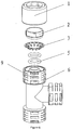
- Figures 1 and 2 show an external sealing type fluid pipe connection device which includes a plug sleeve 1, a push tooth ring 2, an internal tooth snap ring 3, a bearing ring 4, a sealing ring 5 and a pipe joint 6.
- the plug sleeve 1 is placed in the pipe joint 6 (as shown in Figure 2 , the pipe joint 6 is more prominent than the plug sleeve 1) and compressed by using a tool or fixedly fastened in other ways, thereby wrapping the push tooth ring 2, the internal tooth snap ring 3, the bearing ring 4, the sealing ring 5 and other parts in the pipe joint 6 and the plug sleeve 1.
- the internal tooth snap ring 3 is placed on the bearing ring 4, and the sealing ring 5 is arranged below the bearing ring 4.
- the push tooth ring 2 is in sliding fit with the plug sleeve 1.
- a top end of the push tooth ring 2 is basically flush with the pipe joint 6 under the pipe connection state as shown in Figure 2 .
- the top end of the push tooth ring 2 can also be contracted in the pipe joint 6.
- a pipe disassembly tool as shown in Figure 3 is provided with a fixed handle 10 for being connected with a clamping part 11, and provided with a movable handle 12 for being connected with an ejector block 13, while the movable handle 12 is hinged with the fixed handle 10 at their rear parts.
- the clamping part 11 When a pipe is being disassembled, the clamping part 11 is firstly used for clamping the pipe joint 6, then the ejector block 13 is extended by pointing at the top end of the push tooth ring 2, and the middle-rear parts of the two handles are further tightly held for leading the movable handle 12 to approach the fixed handle 10, thereby leading the ejector block 13 to eject the push tooth ring 2 till pushing away internal teeth, and further leading the internal tooth snap ring 3 to release the pipe wall 7.
- the pipe disassembly tool only needs to be operated by a single hand, the other hand can be used for taking out the pipe.
- the pipe disassembly tool is released, the push tooth ring 2 is pushed back to the original position due to the deformation elastic force of the internal teeth, and the internal teeth can also be reset automatically.
- the movable handle 12 and the fixed handle 10 of the pipe disassembly tool adopt the simple and convenient-to-operate hinge way, the two handles are in rotation rather than translation; however, as the pipe axial displacement of the push tooth ring 2 is very short, when the movable handle 12 approaches the fixed handle 10 by rotation, the pipe axial component of the displacement of the ejector block 13 is sufficient to eject the push tooth ring 2 till pushing away the internal teeth.
- the ejector block 13 of the pipe disassembly tool can also be longer, and the longer part can be used as the movable handle 12.
- a pipe disassembly tool according to the present invention is shown in Figures 4 and 5 , the clamping part 11 is connected on the fixed handle 10, the movable handle 12 is hinged with the fixed handle 10, the movable handle 12 is positioned behind the clamping part 11, the fixed handle 10 is positioned behind the ejector block 13, and the connection way between the ejector block 13 and the movable handle 12 is as follows:
- a plurality of external teeth 16 are arranged at the rear part 14 of the lever as shown in Figure 5 , the push rod 17 is hinged with the movable handle 12, and the push rod 17 can select one of the external teeth 16 for pushing against so as to control the stroke of the ejector block 13.
- the push rod 17 can eject different external teeth 16, and then the stroke of the ejector block 13 is different, thereby playing the role of regulating the stroke.
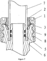
- Figures 6 and 7 show an internal sealing type pipe connection device which includes a plug sleeve 1, a push tooth ring 2, an internal tooth snap ring 3, a sealing ring 5 and a pipe joint 6.
- Convex blocks 8 and 9 which are matched with each other are arranged on the outer wall of the pipe joint 6 and the inner wall of the plug sleeve 1, when assembly, the convex blocks 8 of the plug sleeve 1 is staggered with the convex blocks 9 of the pipe joint for inserting, then the plug sleeve 1 is rotated to lead the convex blocks 8 and 9 to push against each other for fastening fixedly (as shown in Figure 7 , the plug sleeve 1 is more prominent than the pipe joint 6), and other ways can also be used for fastening fixedly, thereby wrapping the internal tooth snap ring 3, the push tooth ring 2, the sealing ring 5 and other parts in the pipe joint 6 and the plug sleeve 1.
- the push tooth ring 2 is in sliding contact with the plug sleeve 1.
- a top end of the push tooth ring 2 is basically flush with the plug sleeve 1 under the pipe connection state as shown in Figure 7 .
- the bearing ring 4 does not need to be arranged.
Landscapes
- Engineering & Computer Science (AREA)
- General Engineering & Computer Science (AREA)
- Mechanical Engineering (AREA)
- Quick-Acting Or Multi-Walled Pipe Joints (AREA)
- Joints With Sleeves (AREA)
- Mutual Connection Of Rods And Tubes (AREA)
Claims (2)
- Rohr-Demontagewerkzeug zur Verwendung mit einer Fluidleitung-Anschlussvorrichtung, aufweisend eine Rohrverbindung (6), eine Steckhülse (1), die an der Rohrverbindung (6) fest befestigt und montiert ist, wird zur Montage eines Innenzahnsprengrings (3) und eines Schub-Zahnkranzes (2) in die Rohrverbindung (6) und die Steckhülse (1) verwendet; wenn ein Rohr angeschlossen ist, klemmt der Innenzahnsprengring (3) die Rohrwand (7), nachdem das Rohr durch die Steckhülse (1), den Schub-Zahnkranz (2) und den Innenzahnsprengring (3) verläuft; der Schub-Zahnkranz (2) schiebt die Innenzähne entlang der Rohreinführrichtung, um den Innenzahnsprengring (3) dazu zu führen, die Rohrwand (7) freizugeben, bevor das Rohr demontiert ist; der Schub-Zahnkranz (2) ist in gleitendem Kontakt mit der Steckhülse (1), und wobei ein oberes Ende des Schub-Zahnkranzes (2) grundsätzlich bündig mit der Steckhülse (1) oder zusammengezogen in der Steckhülse (1) in dem Rohr-Verbindungszustand ist, und wenn die Innenzähne von dem Schub-Zahnkranz (2) weg geschoben sind, ist das obere Ende des Schub-Zahnkranzes (2) in der Steckhülse (1) zusammengezogen, wobei das Rohr-Demontagewerkzeug einen Griff (12) aufweist und der Griff (12) mit einem Auswerferblock (13) verbunden ist, der angepasst ist in die Position zwischen der Steckhülse (1) und der Rohrwand (7) zum Schieben des Schub-Zahnkranzes (2) eingeführt zu werden, und umfassend ein Klemmteil (11), das die Rohrverbindung (6) klemmen kann, und einen feststehenden Griff (10) zum Verbinden des Klemmteils (11), wobei der mit dem Auswerferblock (13) verbundene Griff mit dem feststehenden Griff (10) als ein beweglicher Griff (12) gelenkig ist, wobei der bewegliche Griff (12) hinter dem Klemmteil (11) positioniert ist, der feststehende Griff (10) hinter dem Auswerferblock (13) positioniert ist, dadurch gekennzeichnet, dass- ein Hebel (14) angeordnet ist, dessen Drehpunkt (15) mit dem feststehenden Griff (10) gelenkig ist, der Auswerferblock (13) vor dem Drehpunkt (15) verbunden ist und ein hinterer Teil (14) des Hebels hinter dem Drehpunkt (15) angeordnet ist;- eine Schubstange (17) mit dem beweglichen Griff (12) verbunden ist, wenn sich der bewegliche Griff (12) dem hinteren Teil (14) des Hebels nähert, schiebt die Schubstange (17) den hinteren Teil (14) des Hebels, um den Auswerferblock (13) dazu zu führen, sich dem Klemmteil (11) zu nähern;- zwei Verbindungsstangen (18), die mit dem hinteren Teil (14) des Hebels und dem beweglichen Griff (12) verbunden sind, weiterhin angeordnet sind, wenn der bewegliche Griff (12) von dem hinteren Teil (14) des Hebels weit weg ist, ziehen die zwei Verbindungsstangen (18) den hinteren Teil (14) des Hebels, um den Auswerferblock (13) dazu zu führen, von dem Klemmteil (11) weit weg zu sein, und gleichzeitig die Schubstange (17) dazu zu führen, sich zurückzuziehen.
- Rohr-Demontagewerkzeug nach Anspruch 1, wobei eine Vielzahl von Außenzähnen (16) am hinteren Teil (14) des Hebels angeordnet sind, die Schubstange (17) mit dem bewegbaren Griff (12) gelenkig ist, und die Schubstange (17) einen von den Außenzähnen (16) auswählen kann, um dagegen zu schieben, um den Hub des Auswerferblocks (13) zu steuern.
Applications Claiming Priority (2)
| Application Number | Priority Date | Filing Date | Title |
|---|---|---|---|
| CN200810133606A CN101329000B (zh) | 2008-07-11 | 2008-07-11 | 流体管连接装置及其配套的拆管工具 |
| PCT/CN2009/000775 WO2010003314A1 (zh) | 2008-07-11 | 2009-07-08 | 流体管连接装置及其配套的拆管工具 |
Publications (3)
| Publication Number | Publication Date |
|---|---|
| EP2320118A1 EP2320118A1 (de) | 2011-05-11 |
| EP2320118A4 EP2320118A4 (de) | 2012-12-26 |
| EP2320118B1 true EP2320118B1 (de) | 2016-03-30 |
Family
ID=40204946
Family Applications (1)
| Application Number | Title | Priority Date | Filing Date |
|---|---|---|---|
| EP09793789.0A Not-in-force EP2320118B1 (de) | 2008-07-11 | 2009-07-08 | Anschlussvorrichtung für flüssigkeitsleitung |
Country Status (9)
| Country | Link |
|---|---|
| US (1) | US8608205B2 (de) |
| EP (1) | EP2320118B1 (de) |
| JP (1) | JP2011526992A (de) |
| KR (1) | KR20110039530A (de) |
| CN (1) | CN101329000B (de) |
| AU (1) | AU2009267684B2 (de) |
| CA (1) | CA2730348C (de) |
| RU (1) | RU2464477C1 (de) |
| WO (1) | WO2010003314A1 (de) |
Cited By (1)
| Publication number | Priority date | Publication date | Assignee | Title |
|---|---|---|---|---|
| US12072050B2 (en) | 2019-10-08 | 2024-08-27 | Ipex Technologies Inc. | Push-fit pipe fitting |
Families Citing this family (56)
| Publication number | Priority date | Publication date | Assignee | Title |
|---|---|---|---|---|
| US8205915B1 (en) | 2007-05-25 | 2012-06-26 | Quick Fitting, Inc. | Piping joint assembly system and method |
| US8480134B2 (en) | 2007-05-25 | 2013-07-09 | Quick Fitting, Inc. | Piping joint assembly system and method with sealing ring stabilizer |
| CN102635747A (zh) * | 2008-07-11 | 2012-08-15 | 多升投资有限公司 | 流体管连接装置及其配套的拆管工具 |
| CN101329000B (zh) * | 2008-07-11 | 2012-10-03 | 多升投资有限公司 | 流体管连接装置及其配套的拆管工具 |
| AU2010206066A1 (en) * | 2009-08-03 | 2011-02-17 | Gsa Industries (Aust.) Pty. Ltd. | Pipe coupling |
| CN102062270B (zh) * | 2010-10-29 | 2013-12-11 | 翟秋朗 | 圆管连接器 |
| US8398122B2 (en) | 2010-12-30 | 2013-03-19 | Quick Fitting, Inc. | Push connect joint assembly, system and method |
| WO2013038724A1 (ja) * | 2011-09-14 | 2013-03-21 | 株式会社 オンダ製作所 | 継手及びそれに用いられるスペーサ |
| JP5081336B1 (ja) * | 2011-09-14 | 2012-11-28 | 株式会社オンダ製作所 | 継手及びそれに用いられるスペーサ |
| CN103586836B (zh) * | 2012-08-16 | 2016-09-28 | 上海伊美特实业有限公司 | 一种净水配件拆卸工具 |
| DE102012108791A1 (de) * | 2012-09-18 | 2014-03-20 | Voss Automotive Gmbh | Bausystem für eine Anschlussvorrichtung für Medienleitungen |
| US9551138B2 (en) | 2013-03-15 | 2017-01-24 | Oakville Stamping & Bending Ltd. | Connector for bathtub tailpipe to drain pipe |
| CN203321766U (zh) * | 2013-07-11 | 2013-12-04 | 虞剑勇 | 一种带快速接头的多功能泵 |
| CN103727333B (zh) * | 2013-12-10 | 2016-04-27 | 黎莲威 | 流体管道驳接组件 |
| US9541228B2 (en) | 2013-12-11 | 2017-01-10 | Nibco Inc. | Push-to-connect fitting |
| US10006575B2 (en) | 2013-12-11 | 2018-06-26 | Nibco Inc. | Modular push-to-connect assembly |
| US9447906B2 (en) | 2013-12-11 | 2016-09-20 | Nibco Inc. | Self-locking push-to-connect insert |
| US9777875B2 (en) | 2014-02-26 | 2017-10-03 | Nibco Inc. | Clam shell push-to-connect assembly |
| CN104089125B (zh) * | 2014-07-01 | 2016-09-07 | 日丰企业集团有限公司 | 直插式快接管件 |
| US20160040812A1 (en) * | 2014-08-07 | 2016-02-11 | Wen Sheng Fu Co., Ltd. | Quick Connector Structure for a Pipe |
| US9810359B2 (en) | 2014-10-06 | 2017-11-07 | Spears Manufacturing Co. | Pipe coupling |
| US9765912B2 (en) | 2014-11-06 | 2017-09-19 | Spears Manufacturing Co. | Telescoping pipe coupling |
| US9611970B2 (en) * | 2014-11-06 | 2017-04-04 | Spears Manufacturing Co. | Pipe cap |
| US10253885B2 (en) | 2015-03-24 | 2019-04-09 | Quickhub, Llc | Pipe connector systems, devices and methods |
| US11054035B2 (en) | 2015-03-24 | 2021-07-06 | Quickhub, Llc | Pipe connector systems, devices and methods |
| US11073233B2 (en) | 2015-03-24 | 2021-07-27 | Quickhub, Llc | Pipe connector systems, devices and methods |
| US10100956B2 (en) | 2015-03-24 | 2018-10-16 | Quickhub, Llc | Pipe connector systems, devices and methods |
| US10557578B2 (en) | 2015-03-24 | 2020-02-11 | Quickhub, Llc | Pipe connector systems, devices and methods |
| CN104948799A (zh) * | 2015-06-25 | 2015-09-30 | 何祺晃 | 一种水龙头出水管内置食用级软管的活动接头 |
| CN105221878B (zh) * | 2015-09-06 | 2017-09-29 | 许道泽 | 一种快速连接机构 |
| US9879810B2 (en) | 2015-09-18 | 2018-01-30 | Quick Fitting, Inc. | Push-to-connect joint assembly with protective shield device and method |
| US9562637B1 (en) | 2015-09-22 | 2017-02-07 | Quick Fitting, Inc. | Locking pipe joint assembly, device and method |
| CN105318127B (zh) * | 2015-12-12 | 2017-09-19 | 玉环县豪立信铜业有限公司 | 一种管子的快速连接机构 |
| USD816811S1 (en) * | 2016-01-25 | 2018-05-01 | Poelsan Plastik Sanayi Ve Ticaret Anonim Sirketi | Pipe joint connection |
| US10670173B2 (en) | 2016-03-31 | 2020-06-02 | Quick Fitting, Inc. | Locking pipe joint device with indicator |
| US20180023733A1 (en) * | 2016-07-19 | 2018-01-25 | Wen Sheng Fu Co., Ltd | Pipe adapter |
| US9671049B1 (en) | 2016-07-27 | 2017-06-06 | Quick Fitting, Inc. | Hybrid push-to-connect fitting device and assembly |
| EP3491280B1 (de) * | 2016-07-31 | 2021-10-13 | 9352-4585 Québec Inc. | Sanitärarmatur |
| US10400929B2 (en) | 2017-09-27 | 2019-09-03 | Quick Fitting, Inc. | Fitting device, arrangement and method |
| CN111174011A (zh) * | 2018-11-09 | 2020-05-19 | 郑州宇通客车股份有限公司 | 快插接头 |
| US11287071B2 (en) * | 2019-02-15 | 2022-03-29 | Haier Us Appliance Solutions, Inc. | Quick connect device for connecting tubular members |
| US10969047B1 (en) | 2020-01-29 | 2021-04-06 | Quick Fitting Holding Company, Llc | Electrical conduit fitting and assembly |
| US11035510B1 (en) | 2020-01-31 | 2021-06-15 | Quick Fitting Holding Company, Llc | Electrical conduit fitting and assembly |
| DK3871840T3 (da) * | 2020-02-28 | 2022-05-09 | Ovh | Udløserværktøj til anvendelse med en push-fit-ventil |
| CN113714970B (zh) * | 2020-05-21 | 2022-11-18 | 宝山钢铁股份有限公司 | 一种激光源狭窄空间内快速接头拆卸装置 |
| CN112264787B (zh) * | 2020-10-29 | 2024-04-05 | 华南理工大学 | 一种热管自动穿芯棒设备 |
| US11105452B1 (en) | 2021-02-25 | 2021-08-31 | Quick Fitting Holding Company, Llc | Push-to-connect joint assembly and device |
| IT202100021377A1 (it) | 2021-08-06 | 2023-02-06 | Stucchi Spa | Assemblato di innesto rapido con anello elastico anti-sgancio. |
| USD1053320S1 (en) * | 2021-10-08 | 2024-12-03 | Quick Fitting Holding Company, Llc | Fitting |
| CN114178828B (zh) * | 2021-12-27 | 2024-05-24 | 沈阳航空航天大学 | 一种自动化管路快接装置 |
| CN114636028B (zh) * | 2022-03-21 | 2025-04-11 | 湖北飞歌科技股份有限公司 | 用于水利工程的管道连接与支撑装置 |
| CN115255862A (zh) * | 2022-08-09 | 2022-11-01 | 安徽省佳艺休闲用品有限公司 | 应用于办公椅底座管塞的半自动安装设备 |
| US12345359B2 (en) | 2022-10-12 | 2025-07-01 | Rain Bird Corporation | Tube coupling |
| CN115609539B (zh) * | 2022-11-18 | 2023-03-07 | 盛瑞传动股份有限公司 | 离合器组装方法及工具 |
| CN221054513U (zh) * | 2023-10-27 | 2024-05-31 | 深圳市景在美业有限公司 | 一种灌溉软管管接件及连接头组件 |
| US12442475B2 (en) * | 2025-03-13 | 2025-10-14 | Xiamen Tongjie Technology., Ltd | Push type conduit joint release structure |
Family Cites Families (40)
| Publication number | Priority date | Publication date | Assignee | Title |
|---|---|---|---|---|
| US2635901A (en) * | 1946-12-27 | 1953-04-21 | Alden E Osborn | Joint for smooth-surfaced pipe |
| FR2283381A1 (fr) | 1974-03-15 | 1976-03-26 | Sogemo Automatisation | Perfectionnements apportes aux systemes de raccordement pour conduits, notamment pour tubes plastiques semi-rigides |
| US4123090A (en) * | 1976-07-19 | 1978-10-31 | Imperial-Eastman Corporation | Push-pull fitting |
| JPS5648469U (de) * | 1979-09-20 | 1981-04-30 | ||
| JPS6134702Y2 (de) * | 1981-05-15 | 1986-10-08 | ||
| NL8204763A (nl) * | 1982-12-08 | 1984-07-02 | Johannes Antony De Waal | Inrichting voor het koppelen van buis-of staafeinden. |
| US4586734A (en) * | 1982-12-08 | 1986-05-06 | General Industries, Inc. | Pipe joint assembly |
| JPS6014385U (ja) * | 1983-07-07 | 1985-01-31 | 株式会社 潤工社 | 管継手 |
| JPS60231093A (ja) * | 1984-04-30 | 1985-11-16 | 株式会社 日本ピスコ | 管継手 |
| US4593943A (en) * | 1983-08-23 | 1986-06-10 | Kabushiki Kaisha Nihon Pisco | Tubing joint |
| EP0268251B1 (de) * | 1986-11-18 | 1990-12-27 | Smc Corporation | Rohrkupplung für mehrwandige Rohrleitungen |
| JPH01121667U (de) * | 1988-02-11 | 1989-08-17 | ||
| FR2674309B1 (fr) * | 1991-03-22 | 1993-06-18 | Parker Hannifin Rak Sa | Raccord a griffes perfectionne. |
| DE4137396A1 (de) * | 1991-11-14 | 1993-05-19 | Raymond A & Cie | Loesbare steckverbindung fuer halbstarre rohre |
| JPH05272663A (ja) * | 1992-03-25 | 1993-10-19 | Bridgestone Corp | パイプ差し込み治具 |
| DE29518895U1 (de) * | 1994-11-30 | 1996-02-08 | Widdig, Frank, 90419 Nürnberg | Klemmverbindung für Rohre |
| GB9512974D0 (en) * | 1995-06-26 | 1995-08-30 | Guest John D | Improvements in or relating to tube coupling bodies |
| US5681058A (en) * | 1996-08-20 | 1997-10-28 | Hwang; Biing-Yih | Assembly for joining a pipe to a pipe fitting |
| FR2772458B1 (fr) * | 1997-12-11 | 2000-01-14 | Legris Sa | Dispositif de raccordement rapide d'un tube a un element rigide a bague anti-extraction et temoin d'integrite |
| US6082231A (en) * | 1998-08-19 | 2000-07-04 | Tsai; Kun-Tien | Pliers |
| JP4511738B2 (ja) * | 1998-12-18 | 2010-07-28 | アコー テクノロジー インコーポレーテッド | チューブカップリング |
| GB9905994D0 (en) * | 1999-03-17 | 1999-05-12 | Delta Capillary Prod Ltd | A push fit attachment |
| GB9906299D0 (en) * | 1999-03-19 | 1999-05-12 | British Broadcasting Corp | Watermarking |
| JP3567285B2 (ja) * | 1999-03-19 | 2004-09-22 | 未来工業株式会社 | 樹脂管の接続工具 |
| US6305087B1 (en) * | 2000-07-27 | 2001-10-23 | Hong Chuan Hsian Industries Co., Ltd. | Shears for cutting water pipe and the like |
| TW441451U (en) * | 2000-08-31 | 2001-06-16 | Wu Bi Liang | Disassemble tool set for pipe |
| DE20017921U1 (de) * | 2000-10-19 | 2002-02-28 | Armaturenfabrik Hermann Voss GmbH + Co. KG, 51688 Wipperfürth | Anschlußvorrichtung für Druckmittel-Rohre |
| KR200267995Y1 (ko) * | 2001-09-22 | 2002-03-15 | 구성준 | 파이프 연결구조 |
| CN1323257C (zh) * | 2001-09-29 | 2007-06-27 | 科迈股份有限公司 | 从联结件和相应的联结装置上拆离管子端部的方法 |
| JP3800599B2 (ja) * | 2001-12-14 | 2006-07-26 | 株式会社松阪鉄工所 | 管接続工具 |
| RU2348854C2 (ru) * | 2003-07-04 | 2009-03-10 | Фриатек Акциенгезельшафт | Штекерный разъем |
| CN1324258C (zh) | 2003-10-14 | 2007-07-04 | 安业环球有限公司 | 水或汽管连接装置 |
| JP2005188705A (ja) * | 2003-12-26 | 2005-07-14 | Bridgestone Flowtech Corp | 管継手の管取外し冶具 |
| FR2866095B1 (fr) * | 2004-02-05 | 2007-09-28 | Legris Sa | Rondelle pour dispositif de raccordement de tube, procede de fabrication de rondelle et dispositif de raccordement |
| JP4956183B2 (ja) * | 2004-02-23 | 2012-06-20 | 株式会社ブリヂストン | パイプ継手 |
| JP2006110669A (ja) * | 2004-10-14 | 2006-04-27 | Hitachi Metals Ltd | 配管用接続工具 |
| JP4679240B2 (ja) * | 2005-05-23 | 2011-04-27 | 株式会社ブリヂストン | 管継手 |
| FR2892474B1 (fr) * | 2005-10-26 | 2007-12-28 | Legris Sa | Rondelle d'ancrage non agressive |
| CN2881274Y (zh) | 2005-12-27 | 2007-03-21 | 台州市九洲软管有限公司 | 管用连接头 |
| CN101329000B (zh) * | 2008-07-11 | 2012-10-03 | 多升投资有限公司 | 流体管连接装置及其配套的拆管工具 |
-
2008
- 2008-07-11 CN CN200810133606A patent/CN101329000B/zh not_active Expired - Fee Related
-
2009
- 2009-07-08 RU RU2011103973/06A patent/RU2464477C1/ru not_active IP Right Cessation
- 2009-07-08 EP EP09793789.0A patent/EP2320118B1/de not_active Not-in-force
- 2009-07-08 AU AU2009267684A patent/AU2009267684B2/en not_active Ceased
- 2009-07-08 US US13/003,670 patent/US8608205B2/en active Active
- 2009-07-08 WO PCT/CN2009/000775 patent/WO2010003314A1/zh not_active Ceased
- 2009-07-08 CA CA2730348A patent/CA2730348C/en not_active Expired - Fee Related
- 2009-07-08 KR KR1020117000143A patent/KR20110039530A/ko not_active Ceased
- 2009-07-08 JP JP2011516949A patent/JP2011526992A/ja active Pending
Cited By (1)
| Publication number | Priority date | Publication date | Assignee | Title |
|---|---|---|---|---|
| US12072050B2 (en) | 2019-10-08 | 2024-08-27 | Ipex Technologies Inc. | Push-fit pipe fitting |
Also Published As
| Publication number | Publication date |
|---|---|
| RU2464477C1 (ru) | 2012-10-20 |
| CA2730348C (en) | 2014-05-20 |
| AU2009267684B2 (en) | 2012-08-16 |
| CN101329000A (zh) | 2008-12-24 |
| HK1126847A1 (en) | 2009-09-11 |
| RU2011103973A (ru) | 2012-08-20 |
| KR20110039530A (ko) | 2011-04-19 |
| JP2011526992A (ja) | 2011-10-20 |
| CA2730348A1 (en) | 2010-01-14 |
| US8608205B2 (en) | 2013-12-17 |
| WO2010003314A1 (zh) | 2010-01-14 |
| EP2320118A1 (de) | 2011-05-11 |
| EP2320118A4 (de) | 2012-12-26 |
| CN101329000B (zh) | 2012-10-03 |
| AU2009267684A1 (en) | 2010-01-14 |
| US20110101685A1 (en) | 2011-05-05 |
Similar Documents
| Publication | Publication Date | Title |
|---|---|---|
| EP2320118B1 (de) | Anschlussvorrichtung für flüssigkeitsleitung | |
| US5335530A (en) | Pressing tool for pressing a cylindrical pressing member or a pressing member comprising a cylindrical portion onto a round profile, particularly a pipe conduit | |
| US9421676B2 (en) | Extraction tool for tangless spiral coil insert | |
| CN105402516A (zh) | 带有可枢转夹紧设备的预旋锻装置 | |
| US20240367211A1 (en) | Portable electric power tool for bending elongate objects | |
| CA2850235C (en) | Automatic head-changing screwdriver | |
| US8087280B2 (en) | Spreading pliers | |
| US20170190088A1 (en) | Spring retaining pin for valve stem retention | |
| WO2017076262A1 (zh) | 一种移动旋转式线性覆盖工具 | |
| CN211715503U (zh) | 一种快装快拆结构及出水装置 | |
| US8424558B2 (en) | Wall-mounted faucet that is available for water supply lines of different specifications and sizes | |
| KR101017630B1 (ko) | 마찰용접용 유압척 구조 | |
| EP1967325B1 (de) | Biegevorrichtung für eine Unterlagsscheibe | |
| CN201232823Y (zh) | 流体管连接装置及其配套的拆管工具 | |
| CN102635747A (zh) | 流体管连接装置及其配套的拆管工具 | |
| CN213238683U (zh) | 用于供水管道的同心度校正装置 | |
| CN111577934B (zh) | 一种柱塞式齿条传动二位三通阀 | |
| CN210904578U (zh) | 导丝操作器 | |
| HK1126847B (en) | Fluid pipe connection device and its corresponding tool for dismounting the pipeline | |
| KR200441645Y1 (ko) | 파이프 분리용 전용공구 | |
| US20250327320A1 (en) | Portable electric power tool for bending elongate objects | |
| KR200392534Y1 (ko) | 실리콘 건 | |
| CN218324319U (zh) | 一种淋浴房拉手及一种淋浴门 | |
| CN212947542U (zh) | 一种拆卸工装 | |
| CN112076378A (zh) | 导丝操作器 |
Legal Events
| Date | Code | Title | Description |
|---|---|---|---|
| PUAI | Public reference made under article 153(3) epc to a published international application that has entered the european phase |
Free format text: ORIGINAL CODE: 0009012 |
|
| 17P | Request for examination filed |
Effective date: 20110131 |
|
| AK | Designated contracting states |
Kind code of ref document: A1 Designated state(s): AT BE BG CH CY CZ DE DK EE ES FI FR GB GR HR HU IE IS IT LI LT LU LV MC MK MT NL NO PL PT RO SE SI SK SM TR |
|
| AX | Request for extension of the european patent |
Extension state: AL BA RS |
|
| DAX | Request for extension of the european patent (deleted) | ||
| A4 | Supplementary search report drawn up and despatched |
Effective date: 20121122 |
|
| RIC1 | Information provided on ipc code assigned before grant |
Ipc: B25B 27/10 20060101ALI20121116BHEP Ipc: F16L 37/091 20060101AFI20121116BHEP |
|
| GRAP | Despatch of communication of intention to grant a patent |
Free format text: ORIGINAL CODE: EPIDOSNIGR1 |
|
| INTG | Intention to grant announced |
Effective date: 20150304 |
|
| GRAS | Grant fee paid |
Free format text: ORIGINAL CODE: EPIDOSNIGR3 |
|
| GRAA | (expected) grant |
Free format text: ORIGINAL CODE: 0009210 |
|
| AK | Designated contracting states |
Kind code of ref document: B1 Designated state(s): AT BE BG CH CY CZ DE DK EE ES FI FR GB GR HR HU IE IS IT LI LT LU LV MC MK MT NL NO PL PT RO SE SI SK SM TR |
|
| REG | Reference to a national code |
Ref country code: GB Ref legal event code: FG4D |
|
| REG | Reference to a national code |
Ref country code: CH Ref legal event code: EP |
|
| REG | Reference to a national code |
Ref country code: AT Ref legal event code: REF Ref document number: 785782 Country of ref document: AT Kind code of ref document: T Effective date: 20160415 |
|
| REG | Reference to a national code |
Ref country code: IE Ref legal event code: FG4D |
|
| REG | Reference to a national code |
Ref country code: DE Ref legal event code: R096 Ref document number: 602009037346 Country of ref document: DE |
|
| REG | Reference to a national code |
Ref country code: FR Ref legal event code: PLFP Year of fee payment: 8 |
|
| REG | Reference to a national code |
Ref country code: LT Ref legal event code: MG4D |
|
| PG25 | Lapsed in a contracting state [announced via postgrant information from national office to epo] |
Ref country code: NO Free format text: LAPSE BECAUSE OF FAILURE TO SUBMIT A TRANSLATION OF THE DESCRIPTION OR TO PAY THE FEE WITHIN THE PRESCRIBED TIME-LIMIT Effective date: 20160630 Ref country code: HR Free format text: LAPSE BECAUSE OF FAILURE TO SUBMIT A TRANSLATION OF THE DESCRIPTION OR TO PAY THE FEE WITHIN THE PRESCRIBED TIME-LIMIT Effective date: 20160330 Ref country code: GR Free format text: LAPSE BECAUSE OF FAILURE TO SUBMIT A TRANSLATION OF THE DESCRIPTION OR TO PAY THE FEE WITHIN THE PRESCRIBED TIME-LIMIT Effective date: 20160701 Ref country code: FI Free format text: LAPSE BECAUSE OF FAILURE TO SUBMIT A TRANSLATION OF THE DESCRIPTION OR TO PAY THE FEE WITHIN THE PRESCRIBED TIME-LIMIT Effective date: 20160330 |
|
| REG | Reference to a national code |
Ref country code: NL Ref legal event code: MP Effective date: 20160330 |
|
| REG | Reference to a national code |
Ref country code: AT Ref legal event code: MK05 Ref document number: 785782 Country of ref document: AT Kind code of ref document: T Effective date: 20160330 |
|
| PG25 | Lapsed in a contracting state [announced via postgrant information from national office to epo] |
Ref country code: SE Free format text: LAPSE BECAUSE OF FAILURE TO SUBMIT A TRANSLATION OF THE DESCRIPTION OR TO PAY THE FEE WITHIN THE PRESCRIBED TIME-LIMIT Effective date: 20160330 Ref country code: LV Free format text: LAPSE BECAUSE OF FAILURE TO SUBMIT A TRANSLATION OF THE DESCRIPTION OR TO PAY THE FEE WITHIN THE PRESCRIBED TIME-LIMIT Effective date: 20160330 Ref country code: LT Free format text: LAPSE BECAUSE OF FAILURE TO SUBMIT A TRANSLATION OF THE DESCRIPTION OR TO PAY THE FEE WITHIN THE PRESCRIBED TIME-LIMIT Effective date: 20160330 |
|
| PG25 | Lapsed in a contracting state [announced via postgrant information from national office to epo] |
Ref country code: NL Free format text: LAPSE BECAUSE OF FAILURE TO SUBMIT A TRANSLATION OF THE DESCRIPTION OR TO PAY THE FEE WITHIN THE PRESCRIBED TIME-LIMIT Effective date: 20160330 |
|
| PG25 | Lapsed in a contracting state [announced via postgrant information from national office to epo] |
Ref country code: PL Free format text: LAPSE BECAUSE OF FAILURE TO SUBMIT A TRANSLATION OF THE DESCRIPTION OR TO PAY THE FEE WITHIN THE PRESCRIBED TIME-LIMIT Effective date: 20160330 Ref country code: EE Free format text: LAPSE BECAUSE OF FAILURE TO SUBMIT A TRANSLATION OF THE DESCRIPTION OR TO PAY THE FEE WITHIN THE PRESCRIBED TIME-LIMIT Effective date: 20160330 Ref country code: IS Free format text: LAPSE BECAUSE OF FAILURE TO SUBMIT A TRANSLATION OF THE DESCRIPTION OR TO PAY THE FEE WITHIN THE PRESCRIBED TIME-LIMIT Effective date: 20160730 |
|
| PGFP | Annual fee paid to national office [announced via postgrant information from national office to epo] |
Ref country code: DE Payment date: 20160701 Year of fee payment: 8 |
|
| PG25 | Lapsed in a contracting state [announced via postgrant information from national office to epo] |
Ref country code: SM Free format text: LAPSE BECAUSE OF FAILURE TO SUBMIT A TRANSLATION OF THE DESCRIPTION OR TO PAY THE FEE WITHIN THE PRESCRIBED TIME-LIMIT Effective date: 20160330 Ref country code: PT Free format text: LAPSE BECAUSE OF FAILURE TO SUBMIT A TRANSLATION OF THE DESCRIPTION OR TO PAY THE FEE WITHIN THE PRESCRIBED TIME-LIMIT Effective date: 20160801 Ref country code: ES Free format text: LAPSE BECAUSE OF FAILURE TO SUBMIT A TRANSLATION OF THE DESCRIPTION OR TO PAY THE FEE WITHIN THE PRESCRIBED TIME-LIMIT Effective date: 20160330 Ref country code: SK Free format text: LAPSE BECAUSE OF FAILURE TO SUBMIT A TRANSLATION OF THE DESCRIPTION OR TO PAY THE FEE WITHIN THE PRESCRIBED TIME-LIMIT Effective date: 20160330 Ref country code: RO Free format text: LAPSE BECAUSE OF FAILURE TO SUBMIT A TRANSLATION OF THE DESCRIPTION OR TO PAY THE FEE WITHIN THE PRESCRIBED TIME-LIMIT Effective date: 20160330 Ref country code: CZ Free format text: LAPSE BECAUSE OF FAILURE TO SUBMIT A TRANSLATION OF THE DESCRIPTION OR TO PAY THE FEE WITHIN THE PRESCRIBED TIME-LIMIT Effective date: 20160330 Ref country code: AT Free format text: LAPSE BECAUSE OF FAILURE TO SUBMIT A TRANSLATION OF THE DESCRIPTION OR TO PAY THE FEE WITHIN THE PRESCRIBED TIME-LIMIT Effective date: 20160330 |
|
| PGFP | Annual fee paid to national office [announced via postgrant information from national office to epo] |
Ref country code: FR Payment date: 20160722 Year of fee payment: 8 |
|
| PG25 | Lapsed in a contracting state [announced via postgrant information from national office to epo] |
Ref country code: BE Free format text: LAPSE BECAUSE OF FAILURE TO SUBMIT A TRANSLATION OF THE DESCRIPTION OR TO PAY THE FEE WITHIN THE PRESCRIBED TIME-LIMIT Effective date: 20160330 Ref country code: IT Free format text: LAPSE BECAUSE OF FAILURE TO SUBMIT A TRANSLATION OF THE DESCRIPTION OR TO PAY THE FEE WITHIN THE PRESCRIBED TIME-LIMIT Effective date: 20160330 |
|
| REG | Reference to a national code |
Ref country code: DE Ref legal event code: R097 Ref document number: 602009037346 Country of ref document: DE |
|
| PG25 | Lapsed in a contracting state [announced via postgrant information from national office to epo] |
Ref country code: DK Free format text: LAPSE BECAUSE OF FAILURE TO SUBMIT A TRANSLATION OF THE DESCRIPTION OR TO PAY THE FEE WITHIN THE PRESCRIBED TIME-LIMIT Effective date: 20160330 |
|
| PLBE | No opposition filed within time limit |
Free format text: ORIGINAL CODE: 0009261 |
|
| STAA | Information on the status of an ep patent application or granted ep patent |
Free format text: STATUS: NO OPPOSITION FILED WITHIN TIME LIMIT |
|
| REG | Reference to a national code |
Ref country code: CH Ref legal event code: PL |
|
| 26N | No opposition filed |
Effective date: 20170103 |
|
| PG25 | Lapsed in a contracting state [announced via postgrant information from national office to epo] |
Ref country code: MC Free format text: LAPSE BECAUSE OF FAILURE TO SUBMIT A TRANSLATION OF THE DESCRIPTION OR TO PAY THE FEE WITHIN THE PRESCRIBED TIME-LIMIT Effective date: 20160330 |
|
| PG25 | Lapsed in a contracting state [announced via postgrant information from national office to epo] |
Ref country code: LI Free format text: LAPSE BECAUSE OF NON-PAYMENT OF DUE FEES Effective date: 20160731 Ref country code: CH Free format text: LAPSE BECAUSE OF NON-PAYMENT OF DUE FEES Effective date: 20160731 |
|
| REG | Reference to a national code |
Ref country code: IE Ref legal event code: MM4A |
|
| PG25 | Lapsed in a contracting state [announced via postgrant information from national office to epo] |
Ref country code: SI Free format text: LAPSE BECAUSE OF FAILURE TO SUBMIT A TRANSLATION OF THE DESCRIPTION OR TO PAY THE FEE WITHIN THE PRESCRIBED TIME-LIMIT Effective date: 20160330 |
|
| PG25 | Lapsed in a contracting state [announced via postgrant information from national office to epo] |
Ref country code: IE Free format text: LAPSE BECAUSE OF NON-PAYMENT OF DUE FEES Effective date: 20160708 |
|
| PG25 | Lapsed in a contracting state [announced via postgrant information from national office to epo] |
Ref country code: LU Free format text: LAPSE BECAUSE OF NON-PAYMENT OF DUE FEES Effective date: 20160708 |
|
| REG | Reference to a national code |
Ref country code: DE Ref legal event code: R119 Ref document number: 602009037346 Country of ref document: DE |
|
| REG | Reference to a national code |
Ref country code: FR Ref legal event code: ST Effective date: 20180330 |
|
| PG25 | Lapsed in a contracting state [announced via postgrant information from national office to epo] |
Ref country code: DE Free format text: LAPSE BECAUSE OF NON-PAYMENT OF DUE FEES Effective date: 20180201 |
|
| PG25 | Lapsed in a contracting state [announced via postgrant information from national office to epo] |
Ref country code: HU Free format text: LAPSE BECAUSE OF FAILURE TO SUBMIT A TRANSLATION OF THE DESCRIPTION OR TO PAY THE FEE WITHIN THE PRESCRIBED TIME-LIMIT; INVALID AB INITIO Effective date: 20090708 Ref country code: CY Free format text: LAPSE BECAUSE OF FAILURE TO SUBMIT A TRANSLATION OF THE DESCRIPTION OR TO PAY THE FEE WITHIN THE PRESCRIBED TIME-LIMIT Effective date: 20160330 Ref country code: FR Free format text: LAPSE BECAUSE OF NON-PAYMENT OF DUE FEES Effective date: 20170731 |
|
| PG25 | Lapsed in a contracting state [announced via postgrant information from national office to epo] |
Ref country code: MK Free format text: LAPSE BECAUSE OF FAILURE TO SUBMIT A TRANSLATION OF THE DESCRIPTION OR TO PAY THE FEE WITHIN THE PRESCRIBED TIME-LIMIT Effective date: 20160330 Ref country code: TR Free format text: LAPSE BECAUSE OF FAILURE TO SUBMIT A TRANSLATION OF THE DESCRIPTION OR TO PAY THE FEE WITHIN THE PRESCRIBED TIME-LIMIT Effective date: 20160330 Ref country code: MT Free format text: LAPSE BECAUSE OF NON-PAYMENT OF DUE FEES Effective date: 20160731 |
|
| REG | Reference to a national code |
Ref country code: GB Ref legal event code: 732E Free format text: REGISTERED BETWEEN 20180607 AND 20180613 |
|
| PG25 | Lapsed in a contracting state [announced via postgrant information from national office to epo] |
Ref country code: BG Free format text: LAPSE BECAUSE OF FAILURE TO SUBMIT A TRANSLATION OF THE DESCRIPTION OR TO PAY THE FEE WITHIN THE PRESCRIBED TIME-LIMIT Effective date: 20160330 |
|
| REG | Reference to a national code |
Ref country code: GB Ref legal event code: 732E Free format text: REGISTERED BETWEEN 20211028 AND 20211103 |
|
| PGFP | Annual fee paid to national office [announced via postgrant information from national office to epo] |
Ref country code: GB Payment date: 20220707 Year of fee payment: 14 |
|
| GBPC | Gb: european patent ceased through non-payment of renewal fee |
Effective date: 20230708 |
|
| PG25 | Lapsed in a contracting state [announced via postgrant information from national office to epo] |
Ref country code: GB Free format text: LAPSE BECAUSE OF NON-PAYMENT OF DUE FEES Effective date: 20230708 |