EP2320058B1 - Abwärme nutzende vorrichtung für einen verbrennungsmotor - Google Patents
Abwärme nutzende vorrichtung für einen verbrennungsmotor Download PDFInfo
- Publication number
- EP2320058B1 EP2320058B1 EP09809897.3A EP09809897A EP2320058B1 EP 2320058 B1 EP2320058 B1 EP 2320058B1 EP 09809897 A EP09809897 A EP 09809897A EP 2320058 B1 EP2320058 B1 EP 2320058B1
- Authority
- EP
- European Patent Office
- Prior art keywords
- cooling water
- exhaust gas
- heat exchanger
- temperature
- gas heat
- Prior art date
- Legal status (The legal status is an assumption and is not a legal conclusion. Google has not performed a legal analysis and makes no representation as to the accuracy of the status listed.)
- Active
Links
- 239000002918 waste heat Substances 0.000 title claims description 73
- 238000002485 combustion reaction Methods 0.000 title claims description 22
- 239000000498 cooling water Substances 0.000 claims description 236
- 239000007789 gas Substances 0.000 claims description 122
- 239000012530 fluid Substances 0.000 claims description 30
- 230000005611 electricity Effects 0.000 claims description 28
- 238000001514 detection method Methods 0.000 claims description 26
- 239000007788 liquid Substances 0.000 claims description 15
- 239000000654 additive Substances 0.000 claims description 14
- 230000000996 additive effect Effects 0.000 claims description 7
- 230000008021 deposition Effects 0.000 claims description 7
- 238000000926 separation method Methods 0.000 claims description 6
- 238000001816 cooling Methods 0.000 claims description 5
- 230000007423 decrease Effects 0.000 claims description 5
- 230000003247 decreasing effect Effects 0.000 claims description 5
- 238000001704 evaporation Methods 0.000 claims description 5
- 230000008020 evaporation Effects 0.000 claims description 5
- 239000003507 refrigerant Substances 0.000 description 41
- 230000001105 regulatory effect Effects 0.000 description 21
- LYCAIKOWRPUZTN-UHFFFAOYSA-N Ethylene glycol Chemical compound OCCO LYCAIKOWRPUZTN-UHFFFAOYSA-N 0.000 description 15
- 238000010586 diagram Methods 0.000 description 10
- 238000009835 boiling Methods 0.000 description 6
- 239000007791 liquid phase Substances 0.000 description 6
- 230000007797 corrosion Effects 0.000 description 5
- 238000005260 corrosion Methods 0.000 description 5
- 238000011084 recovery Methods 0.000 description 5
- 230000005764 inhibitory process Effects 0.000 description 3
- 230000001276 controlling effect Effects 0.000 description 2
- 239000003112 inhibitor Substances 0.000 description 2
- 238000010521 absorption reaction Methods 0.000 description 1
- 150000001735 carboxylic acids Chemical class 0.000 description 1
- 238000007796 conventional method Methods 0.000 description 1
- 230000000694 effects Effects 0.000 description 1
- 238000010438 heat treatment Methods 0.000 description 1
- 238000000034 method Methods 0.000 description 1
- 235000011007 phosphoric acid Nutrition 0.000 description 1
- 150000003016 phosphoric acids Chemical class 0.000 description 1
- 230000008929 regeneration Effects 0.000 description 1
- 238000011069 regeneration method Methods 0.000 description 1
- 150000004760 silicates Chemical class 0.000 description 1
- 150000003852 triazoles Chemical class 0.000 description 1
- 230000005514 two-phase flow Effects 0.000 description 1
Images


Classifications
-
- F—MECHANICAL ENGINEERING; LIGHTING; HEATING; WEAPONS; BLASTING
- F02—COMBUSTION ENGINES; HOT-GAS OR COMBUSTION-PRODUCT ENGINE PLANTS
- F02G—HOT GAS OR COMBUSTION-PRODUCT POSITIVE-DISPLACEMENT ENGINE PLANTS; USE OF WASTE HEAT OF COMBUSTION ENGINES; NOT OTHERWISE PROVIDED FOR
- F02G5/00—Profiting from waste heat of combustion engines, not otherwise provided for
- F02G5/02—Profiting from waste heat of exhaust gases
- F02G5/04—Profiting from waste heat of exhaust gases in combination with other waste heat from combustion engines
-
- F—MECHANICAL ENGINEERING; LIGHTING; HEATING; WEAPONS; BLASTING
- F01—MACHINES OR ENGINES IN GENERAL; ENGINE PLANTS IN GENERAL; STEAM ENGINES
- F01K—STEAM ENGINE PLANTS; STEAM ACCUMULATORS; ENGINE PLANTS NOT OTHERWISE PROVIDED FOR; ENGINES USING SPECIAL WORKING FLUIDS OR CYCLES
- F01K13/00—General layout or general methods of operation of complete plants
- F01K13/02—Controlling, e.g. stopping or starting
-
- F—MECHANICAL ENGINEERING; LIGHTING; HEATING; WEAPONS; BLASTING
- F01—MACHINES OR ENGINES IN GENERAL; ENGINE PLANTS IN GENERAL; STEAM ENGINES
- F01K—STEAM ENGINE PLANTS; STEAM ACCUMULATORS; ENGINE PLANTS NOT OTHERWISE PROVIDED FOR; ENGINES USING SPECIAL WORKING FLUIDS OR CYCLES
- F01K23/00—Plants characterised by more than one engine delivering power external to the plant, the engines being driven by different fluids
- F01K23/02—Plants characterised by more than one engine delivering power external to the plant, the engines being driven by different fluids the engine cycles being thermally coupled
- F01K23/06—Plants characterised by more than one engine delivering power external to the plant, the engines being driven by different fluids the engine cycles being thermally coupled combustion heat from one cycle heating the fluid in another cycle
- F01K23/065—Plants characterised by more than one engine delivering power external to the plant, the engines being driven by different fluids the engine cycles being thermally coupled combustion heat from one cycle heating the fluid in another cycle the combustion taking place in an internal combustion piston engine, e.g. a diesel engine
-
- F—MECHANICAL ENGINEERING; LIGHTING; HEATING; WEAPONS; BLASTING
- F01—MACHINES OR ENGINES IN GENERAL; ENGINE PLANTS IN GENERAL; STEAM ENGINES
- F01N—GAS-FLOW SILENCERS OR EXHAUST APPARATUS FOR MACHINES OR ENGINES IN GENERAL; GAS-FLOW SILENCERS OR EXHAUST APPARATUS FOR INTERNAL COMBUSTION ENGINES
- F01N5/00—Exhaust or silencing apparatus combined or associated with devices profiting by exhaust energy
- F01N5/02—Exhaust or silencing apparatus combined or associated with devices profiting by exhaust energy the devices using heat
-
- F—MECHANICAL ENGINEERING; LIGHTING; HEATING; WEAPONS; BLASTING
- F01—MACHINES OR ENGINES IN GENERAL; ENGINE PLANTS IN GENERAL; STEAM ENGINES
- F01P—COOLING OF MACHINES OR ENGINES IN GENERAL; COOLING OF INTERNAL-COMBUSTION ENGINES
- F01P9/00—Cooling having pertinent characteristics not provided for in, or of interest apart from, groups F01P1/00 - F01P7/00
- F01P9/06—Cooling having pertinent characteristics not provided for in, or of interest apart from, groups F01P1/00 - F01P7/00 by use of refrigerating apparatus, e.g. of compressor or absorber type
-
- F—MECHANICAL ENGINEERING; LIGHTING; HEATING; WEAPONS; BLASTING
- F01—MACHINES OR ENGINES IN GENERAL; ENGINE PLANTS IN GENERAL; STEAM ENGINES
- F01N—GAS-FLOW SILENCERS OR EXHAUST APPARATUS FOR MACHINES OR ENGINES IN GENERAL; GAS-FLOW SILENCERS OR EXHAUST APPARATUS FOR INTERNAL COMBUSTION ENGINES
- F01N2240/00—Combination or association of two or more different exhaust treating devices, or of at least one such device with an auxiliary device, not covered by indexing codes F01N2230/00 or F01N2250/00, one of the devices being
- F01N2240/02—Combination or association of two or more different exhaust treating devices, or of at least one such device with an auxiliary device, not covered by indexing codes F01N2230/00 or F01N2250/00, one of the devices being a heat exchanger
-
- F—MECHANICAL ENGINEERING; LIGHTING; HEATING; WEAPONS; BLASTING
- F01—MACHINES OR ENGINES IN GENERAL; ENGINE PLANTS IN GENERAL; STEAM ENGINES
- F01P—COOLING OF MACHINES OR ENGINES IN GENERAL; COOLING OF INTERNAL-COMBUSTION ENGINES
- F01P2050/00—Applications
- F01P2050/24—Hybrid vehicles
-
- F—MECHANICAL ENGINEERING; LIGHTING; HEATING; WEAPONS; BLASTING
- F01—MACHINES OR ENGINES IN GENERAL; ENGINE PLANTS IN GENERAL; STEAM ENGINES
- F01P—COOLING OF MACHINES OR ENGINES IN GENERAL; COOLING OF INTERNAL-COMBUSTION ENGINES
- F01P7/00—Controlling of coolant flow
- F01P7/14—Controlling of coolant flow the coolant being liquid
- F01P7/16—Controlling of coolant flow the coolant being liquid by thermostatic control
- F01P7/162—Controlling of coolant flow the coolant being liquid by thermostatic control by cutting in and out of pumps
-
- F—MECHANICAL ENGINEERING; LIGHTING; HEATING; WEAPONS; BLASTING
- F02—COMBUSTION ENGINES; HOT-GAS OR COMBUSTION-PRODUCT ENGINE PLANTS
- F02G—HOT GAS OR COMBUSTION-PRODUCT POSITIVE-DISPLACEMENT ENGINE PLANTS; USE OF WASTE HEAT OF COMBUSTION ENGINES; NOT OTHERWISE PROVIDED FOR
- F02G2260/00—Recuperating heat from exhaust gases of combustion engines and heat from cooling circuits
-
- Y—GENERAL TAGGING OF NEW TECHNOLOGICAL DEVELOPMENTS; GENERAL TAGGING OF CROSS-SECTIONAL TECHNOLOGIES SPANNING OVER SEVERAL SECTIONS OF THE IPC; TECHNICAL SUBJECTS COVERED BY FORMER USPC CROSS-REFERENCE ART COLLECTIONS [XRACs] AND DIGESTS
- Y02—TECHNOLOGIES OR APPLICATIONS FOR MITIGATION OR ADAPTATION AGAINST CLIMATE CHANGE
- Y02E—REDUCTION OF GREENHOUSE GAS [GHG] EMISSIONS, RELATED TO ENERGY GENERATION, TRANSMISSION OR DISTRIBUTION
- Y02E20/00—Combustion technologies with mitigation potential
- Y02E20/14—Combined heat and power generation [CHP]
-
- Y—GENERAL TAGGING OF NEW TECHNOLOGICAL DEVELOPMENTS; GENERAL TAGGING OF CROSS-SECTIONAL TECHNOLOGIES SPANNING OVER SEVERAL SECTIONS OF THE IPC; TECHNICAL SUBJECTS COVERED BY FORMER USPC CROSS-REFERENCE ART COLLECTIONS [XRACs] AND DIGESTS
- Y02—TECHNOLOGIES OR APPLICATIONS FOR MITIGATION OR ADAPTATION AGAINST CLIMATE CHANGE
- Y02T—CLIMATE CHANGE MITIGATION TECHNOLOGIES RELATED TO TRANSPORTATION
- Y02T10/00—Road transport of goods or passengers
- Y02T10/10—Internal combustion engine [ICE] based vehicles
- Y02T10/12—Improving ICE efficiencies
Definitions
- the present invention relates to waste heat utilization devices for internal combustion engines, and more particularly, to a waste heat utilization device suited for use with an internal combustion engine mounted on a motor vehicle.
- a waste heat utilization device for an internal combustion engine is mounted on a motor vehicle, for example.
- This type of waste heat utilization device is provided with a Rankine cycle including a circulation path for circulating a refrigerant as a working fluid therethrough, and an evaporator for heating the refrigerant by means of waste heat of the engine of the vehicle, an expander for expanding the refrigerant delivered from the evaporator to produce driving force, a condenser for condensing the refrigerant delivered from the expander and a pump for pressurizing the refrigerant delivered from the condenser to be fed to the evaporator are successively inserted in the circulation path.
- the Rankine cycle recovers the waste heat from the engine.
- a heat engine has been disclosed in which ethylene glycol is used as an intermediate medium for absorbing waste heat of the cylinder block of the engine as well as waste heat of the exhaust gas so that the heat absorbed by the ethylene glycol may be transferred to the refrigerant (see Patent Document 1, for example).
- Patent Document 3 which constitutes closest prior art, discloses a system having a first circuit for cooling a combustion engine for a motor vehicle and an Organic-Rankine-circuit.
- the Rankine-circuit there are provided two heat exchangers, the first one providing heat from the combustion engine and the second one providing heat from an exhaust gas heat exchanger of the first circuit.
- the ratio of the amount of waste heat of the engine cylinder block to the amount of waste heat of the exhaust gas is approximately 2:1 to 4:1.
- the ethylene glycol or LLC heated in the exhaust gas heat exchanger is used chiefly to evaporate the refrigerant, so that the refrigerant is insufficiently superheated and expanded to form a two-phase flow, possibly lowering the regeneration efficiency.
- the cooling water circuit is provided with a cooling water pump driven by the engine to circulate the cooling water through the cooling water circulation path.
- a cooling water pump driven by the engine to circulate the cooling water through the cooling water circulation path.
- the present invention was created in view of the above circumstances, and an object thereof is to provide a waste heat utilization device for an internal combustion engine whereby the amount of heat recovered by a Rankine cycle and thus the amount of energy recovered by the waste heat utilization device can be easily and reliably increased while ensuring operation reliability of the waste heat utilization device.
- a waste heat utilization device for an internal combustion engine comprises: a cooling water circuit including a circulation path for circulating cooling water therethrough via the engine, and an exhaust gas heat exchanger inserted in the circulation path to cause heat to transfer from exhaust gas discharged from the engine to part of the cooling water which has been heated while cooling a body of the engine, to additionally heat the cooling water; and a Rankine cycle including a circulation path for circulating a working fluid therethrough, an evaporator for causing heat to transfer from the cooling water delivered from the engine to the working fluid to evaporate the working fluid, a superheater for causing heat to transfer from the cooling water delivered from the exhaust gas heat exchanger to the working fluid delivered from the evaporator to superheat the working fluid, an expander for expanding the working fluid delivered from the superheater to produce driving force, a condenser for condensing the working fluid delivered from the expander, and a pump for feeding the working fluid delivered from the condenser to the evaporator, wherein the
- the cooling water circuit further includes flow rate control means for causing the cooling water delivered from the engine to directly flow into the evaporator while bypassing the exhaust gas heat exchanger and the superheater, to regulate a flow rate of the cooling water flowing into the exhaust gas heat exchanger.
- the cooling water circuit further includes temperature detection means for detecting cooling water temperature at an outlet of the exhaust gas heat exchanger, and the flow rate control means regulates the flow rate of the cooling water flowing into the exhaust gas heat exchanger in accordance with the cooling water temperature detected by the temperature detection means.
- the flow rate control means increases the flow rate of the cooling water flowing into the exhaust gas heat exchanger when the cooling water temperature detected by the temperature detection means is higher than or equal to a preset temperature, and decreases the flow rate of the cooling water flowing into the exhaust gas heat exchanger when the cooling water temperature detected by the temperature detection means is lower than the preset temperature.
- the expander is coupled with an electricity generator for converting the driving force produced by the expander to electric power
- the flow rate control means includes target temperature setting means for setting, as the preset temperature, a cooling water temperature corresponding to a predetermined target electricity generation amount, in accordance with a characteristic relation between the cooling water temperature detected by the temperature detection means and an amount of electric power generated by the electricity generator.
- the target temperature setting means sets, as the preset temperature, a temperature lower than a deposition temperature of an additive added to the cooling water.
- the exhaust gas heat exchanger includes a first heat exchange section and a second heat exchange section successively arranged along a flowing direction of the cooling water
- the temperature detection means detects the cooling water temperature at an outlet of the first heat exchange section
- the cooling water circuit further includes gas-liquid separation means inserted between the first and second heat exchange sections for separating out a vapor produced as a result of evaporation of the cooling water in the first heat exchange section and for delivering the separated vapor to an inlet of the second heat exchange section.
- the cooling water circuit further includes a cooling water pump driven by the engine to circulate the cooling water through the cooling water circulation path
- the flow rate control means includes a bypass passage branching off from a first passage constituting part of the cooling water circulation path and connecting between the engine and the exhaust gas heat exchanger, to allow the cooling water delivered from the engine to directly flow into the evaporator while bypassing the exhaust gas heat exchanger and the superheater, and a linear pump inserted in a portion of the first passage closer to the exhaust gas heat exchanger than a branching point from which the bypass passage diverges, the linear pump being configured to be driven linearly in accordance with the cooling water temperature detected by the temperature detection means, wherein rotating speed of the linear pump is increased when the cooling water temperature detected by the temperature detection means is higher than or equal to the preset temperature, and is decreased when the cooling water temperature detected by the temperature detection means is lower than the preset temperature.
- the cooling water circuit further includes a second passage constituting part of the cooling water circulation path and connecting between the superheater and the evaporator, and a pressure reducing valve inserted in the second passage.
- the cooling water circuit further includes a check valve inserted in a portion of the first passage closer to the exhaust gas heat exchanger than the linear pump is, for preventing reverse flow of the cooling water from the exhaust gas heat exchanger toward the linear pump.
- the Rankine cycle includes the evaporator for causing heat to transfer from the cooling water delivered from the engine to the working fluid to evaporate the working fluid, and the superheater for causing heat to transfer from the cooling water delivered from the exhaust gas heat exchanger to the working fluid delivered from the evaporator, to superheat the working fluid.
- the working fluid is evaporated by the waste heat of the engine body and then superheated by the waste heat of the exhaust gas, whereby the degree to which the working fluid is superheated in the Rankine cycle is heightened, making it possible to increase the amount of energy recovered by the waste heat utilization device.
- the cooling water circuit includes the flow rate control means for causing the cooling water delivered from the engine to directly flow into the evaporator while bypassing the exhaust gas heat exchanger and the superheater, to regulate the flow rate of the cooling water flowing into the exhaust gas heat exchanger.
- the flow rate control means regulates the flow rate of the cooling water flowing into the exhaust gas heat exchanger in accordance with the cooling water temperature detected by the temperature detection means. It is therefore possible to avoid a situation where the flow rate of the cooling water flowing into the exhaust gas heat exchanger is so small that the temperature of the cooling water flowing into the superheater becomes excessively high, or the flow rate of the cooling water flowing into the exhaust gas heat exchanger is so large that the temperature of the cooling water flowing into the superheater becomes excessively low, thus making it possible to efficiently heighten the degree of superheating of the working fluid in the Rankine cycle.
- the flow rate control means increases the flow rate of the cooling water flowing into the exhaust gas heat exchanger when the cooling water temperature detected by the temperature detection means is higher than or equal to the preset temperature, and decreases the flow rate of the cooling water flowing into the exhaust gas heat exchanger when the cooling water temperature detected by the temperature detection means is lower than the preset temperature.
- the flow rate control means includes the target temperature setting means for setting, as the preset temperature, a cooling water temperature corresponding to the predetermined target electricity generation amount, in accordance with the characteristic relation between the cooling water temperature detected by the temperature detection means and the amount of electric power generated by the electricity generator.
- the target temperature setting means sets, as the preset temperature, a temperature lower than the deposition temperature of the additive added to the cooling water. Since the additive is therefore not deposited inside the exhaust gas heat exchanger, lowering in the heat transfer performance of the exhaust gas heat exchanger due to deposition of the additive as well as lowering in corrosion inhibition performance of the cooling water can be prevented, making it possible to reliably increase the energy recovery amount of the waste heat utilization device.
- the cooling water circuit further includes the gas-liquid separation means inserted between the first and second heat exchange sections for separating out the vapor produced as a result of evaporation of the cooling water in the first heat exchange section and for delivering the separated vapor to the inlet of the second heat exchange section. Since the liquid containing the additive does not flow into the second heat exchange section, the cooling water, that is, the vapor of the cooling water can be superheated in the second heat exchange section to temperatures above the deposition temperature of the additive, making it possible to further heighten the degree to which the working fluid is superheated in the Rankine cycle.
- the flow rate control means preferably includes the bypass passage branching off from the first passage constituting part of the cooling water circulation path and connecting between the engine and the exhaust gas heat exchanger, to allow the cooling water delivered from the engine to directly flow into the evaporator while bypassing the exhaust gas heat exchanger and the superheater, and the linear pump inserted in a portion of the first passage closer to the exhaust gas heat exchanger than the branching point from which the bypass passage diverges, the linear pump being configured to be driven linearly in accordance with the cooling water temperature detected by the temperature detection means, wherein the rotating speed of the linear pump is increased when the cooling water temperature detected by the temperature detection means is higher than or equal to the preset temperature, and is decreased when the cooling water temperature detected by the temperature detection means is lower than the preset temperature.
- the linear pump can be operated, in place of the cooling water pump, to circulate the cooling water through the exhaust gas heat exchanger if the temperature of the cooling water present in the exhaust gas heat exchanger is higher than or equal to the preset temperature. It is therefore possible to prevent the exhaust gas heat exchanger from being excessively heated by the residual heat of the exhaust gas because the cooling water pump is stopped and thus the cooling water is not passed through the exhaust gas heat exchanger, whereby damage to the exhaust gas heat exchanger is avoided. Since the exhaust gas heat exchanger, the cooling water circuit and accordingly, the waste heat utilization device can be protected as a result, operation reliability of the waste heat utilization device is ensured.
- the cooling water circuit further includes the second passage constituting part of the cooling water circulation path and connecting between the superheater and the evaporator, and the pressure reducing valve inserted in the second passage.
- the cooling water circuit further includes the check valve inserted in a portion of the first passage closer to the exhaust gas heat exchanger than the linear pump is, for preventing reverse flow of the cooling water from the exhaust gas heat exchanger toward the linear pump.
- FIG. 1 schematically illustrates an exemplary waste heat utilization device for an internal combustion engine.
- the waste heat utilization device is mounted on a motor vehicle, for example, and comprises a cooling water circuit 4 for cooling an engine (internal combustion engine) 2 of the vehicle, and a Rankine cycle 6 (hereinafter referred to as RC circuit) for recovering waste heat of the engine 2.
- RC circuit Rankine cycle 6
- the cooling water circuit 4 includes a circulation path 5 extending via the engine 2 for circulating cooling water (hereinafter referred to also as LLC) therethrough.
- An exhaust gas heat exchanger 8, a superheater 10, an evaporator 12, a radiator 14, a thermostat 16 and a cooling water pump 18 are successively inserted in the circulation path 5 along the flowing direction of the cooling water to constitute a closed circuit.
- the exhaust gas heat exchanger 8 transfers heat from exhaust gas, which is discharged into an exhaust pipe 9 from the engine 2, to the cooling water (e.g., at 95°C), which is delivered from the engine 2 and has been heated while cooling a cylinder block (engine body) 3 of the engine 2, to additionally heat the cooling water up to a preset temperature Ts (e.g., 130°C) so that the cooling water may boil.
- a preset temperature Ts e.g., 130°C
- a temperature sensor (temperature detection means) 20 is attached to a portion of the circulation path 5 between the exhaust gas heat exchanger 8 and the superheater 10, to detect cooling water temperature Tc at the outlet of the exhaust gas heat exchanger 8.
- the radiator 14 is connected in series with the evaporator 12 and transfers heat from the cooling water, which has been cooled due to the absorption of heat by a refrigerant in the evaporator 12, to outside air or the like, in order to further cool the cooling water.
- the thermostat 16 is a mechanical three-way valve for controlling the amount of the cooling water flowing into the radiator 14 in accordance with the temperature of the cooling water flowing through the thermostat 16.
- the thermostat 16 has two inlet ports and one outlet port. The two inlet ports are connected respectively with a passage 5a of the circulation path 5 extending from the radiator 14 and a radiator-bypassing passage 5c of the circulation path 5.
- the radiator-bypassing passage 5c extends from a passage 5b of the circulation path 5 connecting between the evaporator 12 and the radiator 14 and is connected to the thermostat 16 so as to bypass the radiator 14.
- the amount of the cooling water passed through the radiator 14 is increased or decreased in accordance with the cooling water temperature so that the cooling water temperature and thus the temperature of the cylinder block 3 may be kept at a proper temperature.
- the cooling water pump 18, which is a mechanical pump, is mounted to the engine 2 and driven by the rotation of the engine 2 so that the cooling water may be appropriately circulated through the cooling water circuit 4.
- the RC circuit 6, includes a circulation path 7 for circulating the refrigerant serving as a working fluid, such as R134a.
- the evaporator 12, the superheater 10, an expander 22, a condenser 24, a gas liquid separator 26 and a refrigerant pump (pump) 28 are successively inserted in the circulation path 7 along the flowing direction of the refrigerant to constitute a closed circuit.
- the evaporator 12 transfers heat from the cooling water (e.g., at 110°C) circulated successively through the engine 2, the exhaust gas heat exchanger 8 and the superheater 10, to the refrigerant fed under pressure from the refrigerant pump 28, to cause the refrigerant to evaporate at a predetermined evaporation temperature (e.g., 90°C). Since the heat of the cooling water is absorbed due to the evaporation of the refrigerant, the cooling water temperature drops, for example, to 100°C.
- a predetermined evaporation temperature e.g. 90°C
- the superheater 10 transfers heat from the cooling water (130°C) delivered from the exhaust gas heat exchanger 8, to the refrigerant delivered from the evaporator 12 so that the refrigerant may be superheated (e.g., at 110°C).
- the expander 22 is a rotating device for producing a driving force by expanding the superheated refrigerant delivered from the superheater 10.
- the expander 22 is mechanically coupled with an electricity generator 30, which converts the driving force produced by the expander 22 to electric power so that the generated electric power may be used by devices external to the waste heat utilization device.
- the condenser 24 is a heat radiator for transferring heat from the refrigerant delivered from the expander 22 to the outside air or the like, to condense the refrigerant into a liquid phase.
- the gas-liquid separator 26 separates the refrigerant condensed by the condenser 24 into two, gas and liquid phases and supplies only the separated liquid-phase refrigerant to the refrigerant pump 28.
- the refrigerant pump 28 pressurizes the liquid-phase refrigerant separated by the gas-liquid separator 26 and feeds the refrigerant under pressure to the evaporator 12 so that the refrigerant may be appropriately circuited through the RC circuit 6.
- the cooling water circuit 4 and the RC circuit 6 configured as described above are controlled by an ECU 32, which is an electronic control unit for performing integrated control of the vehicle.
- the ECU 32 is electrically connected with the driving section of the refrigerant pump 28.
- the ECU 32 controls the operation of the refrigerant pump 28 in accordance with operating conditions of the engine 2, so that the waste heat utilization device recovers waste heat of the engine 2, that is, waste heat of the cylinder block 3 and waste heat of the exhaust gas, through the medium of the cooling water.
- the refrigerant is evaporated in the evaporator 12 by the waste heat of the cylinder block 3 and then is superheated in the superheater 10 by the heat of the exhaust gas.
- the refrigerant thus heated in stages into a superheated state is supplied to the expander 22 so that the electricity generator 30 may generate energy available to devices external to the waste heat utilization device.
- the cooling water circuit 4 includes a bypass passage 34, which allows the cooling water from the engine 2 to flow directly into the evaporator 12 while bypassing the exhaust gas heat exchanger 8 and the superheater 10.
- a flow regulating valve 36 is inserted in the bypass passage 34 to regulate the flow rate of the cooling water flowing through the bypass passage 34, and has a driving section electrically connected to the ECU 32.
- the aforementioned temperature sensor 20 is also electrically connected to the ECU 32.
- the ECU 32 In accordance with the input signal from the temperature sensor 20, the ECU 32 outputs a drive signal to the driving section of the flow regulating valve 36, to perform flow rate control by regulating the flow rate of the cooling water flowing through the bypass passage 34 and thereby controlling the flow rate of the cooling water flowing into the exhaust gas heat exchanger 8 (flow rate control means).
- the control routine Upon start of the flow rate control, the control routine first proceeds to S1, in which it is determined whether or not the cooling water temperature Tc detected by the temperature sensor 20 indicates a value higher than or equal to the preset temperature Ts (Tc ⁇ Ts). If the result of the decision is affirmative (Yes), that is, if it is judged that the relation Tc ⁇ Ts is fulfilled, the control routine proceeds to S2. On the other hand, if the result of the decision is negative (No), that is, if it is judged that the relation Tc ⁇ Ts is not fulfilled, the control routine proceeds to S3.
- the opening of the flow regulating valve 36 is controlled such that the flow rate Fe of the cooling water flowing into the exhaust gas heat exchanger 8 is increased when the cooling water temperature Tc detected by the temperature sensor 20 is higher than or equal to the preset temperature Ts.
- the flow rate Fe of the cooling water flowing into the exhaust gas heat exchanger 8 is decreased.
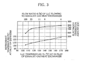
- FIG. 3 is a characteristic diagram illustrating the relationship among the ratio R (%) of the flow rate Fe to a total flow rate F of the cooling water delivered from the engine 2, the cooling water temperature Tc (°C) detected by the temperature sensor 20, and the amount of electricity E (W) generated by the electricity generator 30.
- the preset temperature Ts is determined on the basis of the characteristic diagram as a cooling water temperature Tc corresponding to a predetermined electricity generation amount E (target temperature setting means).
- the characteristic diagram of FIG. 3 shows that the electricity generation amount E sharply increases as the cooling water temperature Tc rises up to about 120°C, and that after the cooling water temperature Tc becomes higher than about 120°C, the electricity generation amount E increases only gently with increase in the cooling water temperature Tc.
- the cooling water contains additives serving as a corrosion inhibitor, such as phosphoric acids, carboxylic acids, triazoles and silicates. If the flow ratio R is close to 0%, in other words, if the LLC completely evaporates, the corrosion inhibitor is undesirably deposited.
- a target value of the electricity generation amount E is set to about 740 (W), and the flow regulating valve 36 is controlled such that the flow ratio R is approximately 11% when the cooling water temperature Tc detected by the temperature sensor 20 is equal to the preset temperature Ts of 130°C, which is higher than the cooling water temperature Tc of 120°C to allow an appropriate margin.
- the refrigerant is evaporated by the waste heat of the cylinder block 3 and is then superheated by the waste heat of the exhaust gas.
- the cooling water temperature Tc at the outlet of the exhaust gas heat exchanger 8 in other words, the temperature of the cooling water flowing into the superheater 10 can be substantially increased up to 130°C by a simple control operation in which the ratio of the flow rate Fe of the cooling water flowing into the exhaust gas heat exchanger 8 to the total flow rate F is reduced to about 11%. Accordingly, the degree to which the refrigerant is superheated in the RC circuit 6 can be effectively heightened.
- the flow rate Fe of the cooling water flowing into the exhaust gas heat exchanger 8 is controlled in accordance with the cooling water temperature Tc detected by the temperature sensor 20, so that a situation can be avoided where the flow rate Fe is so small that the temperature Tc of the cooling water flowing into the superheater 10 becomes excessively high or where the flow rate Fe is so large that the temperature Tc of the cooling water flowing into the superheater 10 becomes excessively low. Also for this reason, the degree to which the refrigerant is superheated in the RC circuit 6 can be efficiently heightened.
- the cooling water temperature Tc of 130°C is determined, on the basis of the characteristic diagram of FIG. 3 , as the temperature up to which the electricity generation amount E sharply rises with increase in the cooling water temperature Tc, that is, high electricity generation efficiency is achieved, and this temperature 130°C is set as the preset temperature Ts. It is therefore possible to efficiently increase the amount of electricity generated by the electricity generator 30 and thus the energy recovery amount of the waste heat utilization device.
- the preset temperature Ts is set to a temperature lower than the temperature at which the cooling water is completely evaporated. Accordingly, the additives in the cooling water are not deposited inside the exhaust gas heat exchanger 8, thus reliably preventing lowering in the heat transfer performance of the exhaust gas heat exchanger 8 due to the deposited additives as well as lowering in the corrosion inhibition performance of the cooling water. It is therefore possible to reliably increase the energy recovery amount of the waste heat utilization device.
- FIG. 4 schematically illustrates a waste heat utilization device for an internal combustion engine according to the embodiment.
- the embodiment differs from the first example in that the heat exchange section of the exhaust gas heat exchanger 8 is divided into two parts. In the other respects, the configuration of the embodiment is identical with that of the first example.
- the heat exchange section of the exhaust gas heat exchanger 8 is divided into a first heat exchange section 8A and a second heat exchange section 8B, which are successively arranged along the flowing direction of the cooling water.
- a gas-liquid separator 38 is inserted between the first and second heat exchange sections 8A and 8B.
- the gas-liquid separator 38 separates the cooling water delivered from the first heat exchange section 8A into gas and liquid phases, and returns only the liquid-phase cooling water containing the additives to the inlet of the evaporator 12 through a return passage 40 extending therefrom to the inlet of the evaporator 12 (gas-liquid separation means).
- the temperature sensor 20 is attached to a passage between the first heat exchange section 8A and the gas-liquid separator 38, to detect the cooling water temperature Tc at the outlet of the first heat exchange section 8A.
- the flow rate control is performed to regulate the flow rate Fe of the cooling water flowing into the exhaust gas heat exchanger 8.
- the degree to which the refrigerant is superheated in the RC circuit 6 can be raised to significantly increase the amount of energy recovered by the waste heat utilization device, like the first example.
- the cooling water that is, the vapor from which the additives have been separated out by the gas-liquid separator 38
- the cooling water can be additionally heated in the second heat exchange section 8B up to temperatures above the deposition temperature of the additives, to produce superheated vapor.
- the temperature Tc of the cooling water flowing into the superheater 10 can be raised to the maximum while at the same time preventing deposition of the additives inside the exhaust gas heat exchanger 8 as well as lowering in the corrosion inhibition performance of the cooling water.
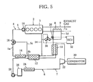
- FIG. 5 schematically illustrates a waste heat utilization device for an internal combustion engine according to the second example.
- the flow regulating valve 36 is inserted in the passage leading to the exhaust gas heat exchanger 8, as distinct from the first example.
- the configuration of the second example is identical with that of the first example.
- bypass passage 34 branches off from a passage (first passage) 5d of the circulation path 5 connecting between the engine 2 and the exhaust gas heat exchanger 8, and the flow regulating valve 36 is inserted in a portion of the passage 5d closer to the exhaust gas heat exchanger 8 than the branching point from which the bypass passage 34 diverges.
- the ECU 32 outputs a drive signal to the driving section of the flow regulating valve 36 in accordance with the input signal from the temperature sensor 20, to execute flow rate control similar to those of the foregoing examples and embodiment (flow rate control means).
- the flow regulating valve 36 is controlled so as to operate in a manner reverse to that of the flow regulating valve 36 of the foregoing embodiments. Specifically, when the cooling water temperature Tc is higher than or equal to the preset temperature Ts (Tc ⁇ Ts) and thus it is judged that the relation Tc ⁇ Ts is fulfilled, the flow regulating valve 36 is driven in the valve opening direction to increase the flow rate Fe of the cooling water flowing into the exhaust gas heat exchanger 8, and when it is judged that the relation Tc ⁇ Ts is not fulfilled, the flow regulating valve 36 is driven in the valve closing direction to decrease the flow rate Fe of the cooling water flowing into the exhaust gas heat exchanger 8, so that the flow ratio R may be about 11% when the cooling water temperature is equal to the preset temperature Ts of 130°.
- the degree to which the refrigerant is superheated in the RC circuit 6 can be heightened to substantially increase the energy recovery amount of the waste heat utilization device, like the foregoing examples and embodiment.
- the flow rate control is performed in the same manner as in the above examples and embodiment such that the cooling water is made to flow into the exhaust gas heat exchanger 8 at a small flow rate with the flow ratio R set to about 11%. Since, in the second example in particular, the flow regulating valve 36 is inserted in the portion of the passage 5d closer to the exhaust gas heat exchanger 8 than the branching point from which the bypass passage 34 diverges, the effective flow area of the flow regulating valve 36 may be small, compared with the case where the flow regulating valve 36 is inserted in the bypass passage 34, whereby the flow regulating valve 36 can be reduced in size. It is therefore possible to reduce the costs of the flow regulating valve 36, the cooling water circuit 4 and thus the waste heat utilization device.
- FIG. 6 schematically illustrates a waste heat utilization device for an internal combustion engine according to the third example.
- the third example differs from the second example in that the flow regulating valve 36 is replaced by a linear pump 42.
- the configuration of the third example is identical with that of the second example.
- the linear pump 42 is an electric pump having a driving section electrically connected to the ECU 32 so that the linear pump 42 may be driven linearly in accordance with the cooling water temperature Tc detected by the temperature sensor 20.
- the ECU 32 outputs a drive signal to the driving section of the linear pump 42 in accordance with the input signal from the temperature sensor 20, to perform flow rate control similar to those executed by the above examples and embodiment (flow rate control means).
- the linear pump 42 is controlled in the following manner: When the cooling water temperature Tc is higher than or equal to the preset temperature Ts (Tc ⁇ Ts) and thus it is judged that the relation Tc ⁇ Ts is fulfilled, the rotating speed of the linear pump 42 is raised to increase the flow rate Fe of the cooling water flowing into the exhaust gas heat exchanger 8, and when it is judged that the relation Tc ⁇ Ts is not fulfilled, the rotating speed of the linear pump 42 is lowered to decrease the flow rate Fe of the cooling water flowing into the exhaust gas heat exchanger 8, so that the flow ratio R may be approximately 11% when the cooling water temperature is equal to the preset temperature Ts of 130°.
- the degree of superheating of the refrigerant in the RC circuit 6 can be raised to significantly increase the amount of energy recovered by the waste heat utilization device, like the foregoing examples and embodiment.
- the linear pump 42 can be operated, in place of the cooling water pump 18, to circulate the cooling water through the exhaust gas heat exchanger 8 if the cooling water present in the exhaust gas heat exchanger 8 is at a temperature higher than or equal to the preset temperature Ts. It is therefore possible to avoid a situation where the exhaust gas heat exchanger 8 is excessively heated by the residual heat of the exhaust gas because the cooling water is not circulated through the exhaust gas heat exchanger 8 due to stoppage of the cooling water pump 18, thereby preventing damage to the exhaust gas heat exchanger 8. Since the exhaust gas heat exchanger 8, the cooling water circuit 4 and thus the waste heat utilization device can be protected, operation reliability of the waste heat utilization device can be ensured.
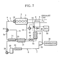
- FIG. 7 schematically illustrates a waste heat utilization device for an internal combustion engine according to the fourth example.
- the configuration of the fourth example is identical with that of the third example.
- the pressure reducing valve 44 is inserted in a passage (second passage) 5e of the circulation path 5 connecting between the superheater 10 and the evaporator 12, to reduce the pressure P of the cooling water delivered from the superheater 10 to a preset pressure Ps so that the cooling water with the reduced pressure Ps may be supplied to the evaporator 12.
- the check valve 46 is inserted in that portion of the passage 5d which is closer to the exhaust gas heat exchanger 8 than the linear pump 42 is, to prevent the cooling water from flowing backward from the exhaust gas heat exchanger 8 to the linear pump 42.
- the degree to which the refrigerant is superheated in the RC circuit 6 can be raised to significantly increase the amount of energy recovery by the waste heat utilization device, like the foregoing examples and embodiment.
- the boiling cooling water is condensed by the superheater 10 and is then supplied to the evaporator 12 after the pressure thereof is reduced by the pressure reducing valve 44. Accordingly, the design of circuit withstanding pressure, which has to be based on the assumption that the cooling water boils in the exhaust gas heat exchanger 8, is needed only for a segment of the circulation path 5 extending from the linear pump 42 to the pressure reducing valve 44 and including the exhaust gas heat exchanger 8 and the superheater 10.
- the waste heat utilization device is mounted on the motor vehicle equipped with the engine 2 as a drive source.
- the waste heat utilization device may be mounted on a hybrid vehicle of which the drive source is constituted by the combination of the engine 2 and an electric motor, not shown.
- the engine 2 is frequently stopped each time the drive source of the vehicle is switched from the engine 2 to the electric motor, with the result that the cooling water pump 18 is also frequently stopped.
- the cooling water circuit 4 and thus the waste heat utilization device can be reliably protected with ease, providing the advantage that the operation reliability of the waste heat utilization device can be secured.
Landscapes
- Engineering & Computer Science (AREA)
- Chemical & Material Sciences (AREA)
- Combustion & Propulsion (AREA)
- Mechanical Engineering (AREA)
- General Engineering & Computer Science (AREA)
- Physics & Mathematics (AREA)
- Thermal Sciences (AREA)
- Engine Equipment That Uses Special Cycles (AREA)
Claims (4)
- Abwärmenutzungsvorrichtung für einen Verbrennungsmotor (2), aufweisend:einen Kühlwasserkreis (4), der einen Zirkulationspfad (5) zum Hindurchzirkulieren von Kühlwasser mittels des Motor (2) und einen Abgaswärmetauscher (8), der in den Zirkulationspfad (5) eingefügt ist, enthält, um zu veranlassen, dass Wärme von dem von dem Motor (2) ausgestoßenen Abgas zu einem Teil des Kühlwassers, das während des Kühlens eines Körpers des Motors aufgeheizt wurde, übertragen wird, um das Kühlwasser zusätzlich aufzuheizen; undeine Rankine-Kreis (6), der einen Zirkulationspfad (7) zum Hindurchzirkulieren eines Arbeitsfluids, einen Verdampfer (12), um zu veranlassen, dass Wärme von dem von dem Motor (2) gelieferten Kühlwasser zu dem Arbeitsfluid übertragen wird, um das Arbeitsfluid zu verdampfen, einen Überhitzer (10), um zu veranlassen, dass Wärme von dem von dem Abgaswärmetauscher (8) gelieferten Kühlwasser zu dem von dem Verdampfer (12) gelieferten Arbeitsfluid übertragen wird, um das Arbeitsfluid zu überhitzen, einen Expander (22) zum Dekomprimieren des von dem Überhitzer (10) gelieferten Arbeitsfluids, um eine Antriebskraft zu erzeugen, einen Kondensator (24) zum Kondensieren des von dem Expander (22) gelieferten Arbeitsfluids, und eine Pumpe (28) zum Zuführen des von dem Kondensator (24) gelieferten Arbeitsfluids zu dem Verdampfer (12) enthält, wobei der Verdampfer (12), der Überhitzer (10), der Expander (22), der Kondensator (24) und die Pumpe (28) nacheinander in dem Arbeitsfluidzirkulationspfad eingebracht sind, wobeider Kühlwasserkreis (4) ferner ein Durchflussratensteuerungsmittel (32) enthält, um zu veranlassen, dass das von dem Motor (2) gelieferte Kühlwasser direkt in den Verdampfer (12) strömt, während es den Abgaswärmetauscher (8) und den Überhitzer (10) umgeht, um eine Durchflussrate des in den Abgaswärmetauscher (8) strömenden Kühlwassers zu regulieren, und der Kühlwasserkreis (4) ferner ein Temperaturerfassungsmittel (20) zum Erfassen einer Kühlwassertemperatur an einem Auslass des Abgaswärmetauschers (8) enthält,wobei das Durchflussratensteuerungsmittel (32) die Durchflussrate des in den Abgaswärmetauscher (8) strömenden Kühlwassers erhöht, wenn die durch das Temperaturerfassungsmittel (20) erfasste Kühlwassertemperatur höher als oder gleich einer voreingestellten Temperatur ist, und die Durchflussrate des in den Abgaswärmetauscher (8) strömenden Kühlwassers reduziert, wenn die durch das Temperaturerfassungsmittel (20) erfasste Kühlwassertemperatur niedriger als die voreingestellte Temperatur ist, und wobeider Expander zum Umwandeln der durch den Expander (22) erzeugten Antriebskraft in elektrische Leistung mit einem elektrischen Generator (30) gekoppelt istdadurch gekennzeichnet,dass das Durchflussratensteuerungsmittel (32) ein Soll-temperatureinstellmittel zum Einstellen einer Kühlwassertemperatur als die voreingestellte Temperatur entsprechend einer vorbestimmten Sollstromerzeugungsmenge in Übereinstimmung mit einem charakteristischen Verhältnis zwischen der durch das Temperaturerfassungsmittel (20) erfassten Kühlwassertemperatur und einer Menge von durch den elektrischen Generator (30) erzeugten elektrischen Leistung ist,dass das Solltemperatureinstellmittel eine Temperatur, die niedriger als eine Ablagerungstemperatur eines zu dem Kühlwasser hinzugefügten Additivs ist, als die voreingestellte Temperatur einstellt, unddass der Abgaswärmetauscher (8) einen ersten Wärmetauschabschnitt (8A) und einen zweiten Wärmetauschabschnitt (8B) enthält, die entlang einer Strömungsrichtung des Kühlwassers nacheinander angeordnet sind,dass das Temperaturerfassungsmittel (20) die Kühlwassertemperatur an einem Auslass des ersten Wärmetauschabschnitts (8A) erfasst, unddass der Kühlwasserkreis (4) ferner ein zwischen dem ersten und dem zweiten Wärmetauschabschnitt eingefügtes Gas-Flüssigkeits-Abscheidungsmittel (38) zum Abscheiden eines als ein Verdampfungsergebnis des Kühlwassers in dem ersten Wärmetauschabschnitt (8A) erzeugten Dampfs und zum Liefern des abgeschiedenen Dampfs zu einem Einlass des zweiten Wärmetauschabschnitts (8B) enthält.
- Abwärmenutzungsvorrichtung für einen Verbrennungsmotor (2) gemäß Anspruch 1, dadurch gekennzeichnet,
dass der Kühlwasserkreis (4) ferner eine durch den Motor (2) angetriebene Kühlwasserpumpe (18) enthält, um das Kühlwasser durch den Kühlwasserzirkulationspfad (5) zu zirkulieren, und
dass das Durchflussratensteuerungsmittel (32) eine Umgehungspassage (34), die von einer ersten Passage (5d), die einen Teil des Kühlwasserzirkulationspfads (5) bildet und zwischen dem Motor (2) und dem Abgaswärmetauscher (8) verbindet, abzweigt, um es zu ermöglichen, dass von dem Motor (2) geliefertes Kühlwasser direkt in den Verdampfer (12) strömt, während es den Abgaswärmetauscher (8) und den Überhitzer (10) umgeht, und eine in einen Abschnitt der ersten Passage (5d), der näher als ein Abzweigpunkt, von dem die Umgehungspassage (34) auseinander geht, an dem Abgaswärmetauscher (8) ist, eingebrachte Linearpumpe (42) enthält, wobei die Linearpumpe ausgebildet ist, linear in Übereinstimmung mit der durch das Temperaturerfassungsmittel (20) erfassten Kühlwassertemperatur angetrieben zu werden, wobei die Drehzahl der Linearpumpe (42) erhöht wird, wenn die durch das Temperaturerfassungsmittel (20) erfasste Kühlwassertemperatur höher als die oder gleich der voreingestellten Temperatur ist, und verringert wird, wenn die durch das Temperaturerfassungsmittel (20) erfasste Kühlwassertemperatur niedriger als die voreingestellte Temperatur ist. - Abwärmenutzungsvorrichtung gemäß Anspruch 2, wobei der Kühlwasserkreis (4) ferner eine zweite Passage (5e) enthält, die einen Teil des Kühlwasserzirkulationspfads (5) bildet und zwischen dem Überhitzer (10) und dem Verdampfer (12) verbindet, und ein Druckreduzierungsventil (44) in die zweite Passage (5e) eingefügt ist.
- Abwärmenutzungsvorrichtung gemäß Anspruch 3, wobei der Kühlwasserkreis (4) ferner ein in einen Abschnitt der ersten Passage (5d), der näher an dem Abgaswärmetauscher (8) als die Linearpumpe (42) ist, eingefügtes Rückschlagventil (46) enthält, um einen Rückstrom des Kühlwassers von dem Abgaswärmetauscher (8) zu der Linearpumpe (42) hin zu verhindern.
Applications Claiming Priority (2)
| Application Number | Priority Date | Filing Date | Title |
|---|---|---|---|
| JP2008216647 | 2008-08-26 | ||
| PCT/JP2009/064781 WO2010024246A1 (ja) | 2008-08-26 | 2009-08-25 | 内燃機関の廃熱利用装置 |
Publications (3)
| Publication Number | Publication Date |
|---|---|
| EP2320058A1 EP2320058A1 (de) | 2011-05-11 |
| EP2320058A4 EP2320058A4 (de) | 2011-08-03 |
| EP2320058B1 true EP2320058B1 (de) | 2015-11-25 |
Family
ID=41721414
Family Applications (1)
| Application Number | Title | Priority Date | Filing Date |
|---|---|---|---|
| EP09809897.3A Active EP2320058B1 (de) | 2008-08-26 | 2009-08-25 | Abwärme nutzende vorrichtung für einen verbrennungsmotor |
Country Status (4)
| Country | Link |
|---|---|
| US (1) | US8881523B2 (de) |
| EP (1) | EP2320058B1 (de) |
| JP (1) | JP5476067B2 (de) |
| WO (1) | WO2010024246A1 (de) |
Families Citing this family (65)
| Publication number | Priority date | Publication date | Assignee | Title |
|---|---|---|---|---|
| JP5338731B2 (ja) * | 2010-03-29 | 2013-11-13 | 株式会社豊田自動織機 | 廃熱回生システム |
| WO2012021757A2 (en) * | 2010-08-11 | 2012-02-16 | Cummins Intellectual Property, Inc. | Split radiator design for heat rejection optimization for a waste heat recovery system |
| JP5481737B2 (ja) * | 2010-09-30 | 2014-04-23 | サンデン株式会社 | 内燃機関の廃熱利用装置 |
| JP5553730B2 (ja) * | 2010-11-08 | 2014-07-16 | 日野自動車株式会社 | 廃熱回収システム |
| JP5747494B2 (ja) * | 2010-12-14 | 2015-07-15 | 日産自動車株式会社 | 排気熱交換装置 |
| DE112011104516B4 (de) | 2010-12-23 | 2017-01-19 | Cummins Intellectual Property, Inc. | System und Verfahren zur Regulierung einer EGR-Kühlung unter Verwendung eines Rankine-Kreisprozesses |
| US8826662B2 (en) | 2010-12-23 | 2014-09-09 | Cummins Intellectual Property, Inc. | Rankine cycle system and method |
| DE102012000100A1 (de) | 2011-01-06 | 2012-07-12 | Cummins Intellectual Property, Inc. | Rankine-kreisprozess-abwärmenutzungssystem |
| US9021808B2 (en) | 2011-01-10 | 2015-05-05 | Cummins Intellectual Property, Inc. | Rankine cycle waste heat recovery system |
| EP3396143B1 (de) | 2011-01-20 | 2020-06-17 | Cummins Intellectual Properties, Inc. | Verbrennungsmotor mit rankine-kreislauf-wärmerückgewinnungssystem |
| KR200456118Y1 (ko) | 2011-06-07 | 2011-10-13 | 사단법인 한국선급 | 온도차를 이용한 발전장치를 장착한 에너지절약형 선박 |
| JP6158182B2 (ja) * | 2011-08-19 | 2017-07-05 | イー・アイ・デュポン・ドウ・ヌムール・アンド・カンパニーE.I.Du Pont De Nemours And Company | 熱から機械的エネルギーを発生させるための有機ランキンサイクルのための方法および組成物 |
| JP5804879B2 (ja) * | 2011-09-30 | 2015-11-04 | 日産自動車株式会社 | 廃熱利用装置 |
| EP2762713B1 (de) * | 2011-09-30 | 2015-10-14 | Nissan Motor Co., Ltd. | Rankine-kreislauf |
| US8931275B2 (en) * | 2012-01-24 | 2015-01-13 | GM Global Technology Operations LLC | Adaptive heat exchange architecture for optimum energy recovery in a waste heat recovery architecture |
| JP5842668B2 (ja) * | 2012-02-28 | 2016-01-13 | 日産自動車株式会社 | ランキンサイクル |
| CN102644499B (zh) * | 2012-04-25 | 2016-09-21 | 清华大学 | 基于布雷顿循环的余热利用系统及余热利用发动机 |
| US9874130B2 (en) * | 2012-05-10 | 2018-01-23 | Volvo Truck Corporation | Vehicle internal combustion engine arrangement comprising a waste heat recovery system for compressing exhaust gases |
| US8893495B2 (en) | 2012-07-16 | 2014-11-25 | Cummins Intellectual Property, Inc. | Reversible waste heat recovery system and method |
| CN103615338A (zh) * | 2012-11-12 | 2014-03-05 | 摩尔动力(北京)技术股份有限公司 | 内燃机余热双工质动力系统 |
| US9140209B2 (en) | 2012-11-16 | 2015-09-22 | Cummins Inc. | Rankine cycle waste heat recovery system |
| CN105051350B (zh) | 2013-01-17 | 2018-09-25 | 尼马尔·穆利 | 内部冷却内燃机及其方法 |
| JP6020242B2 (ja) * | 2013-02-18 | 2016-11-02 | トヨタ自動車株式会社 | 内燃機関の廃熱利用装置 |
| AU2014225990B2 (en) | 2013-03-04 | 2018-07-26 | Echogen Power Systems, L.L.C. | Heat engine systems with high net power supercritical carbon dioxide circuits |
| US9845711B2 (en) | 2013-05-24 | 2017-12-19 | Cummins Inc. | Waste heat recovery system |
| DE102013011477A1 (de) * | 2013-07-09 | 2015-01-15 | Volkswagen Aktiengesellschaft | Antriebseinheit für ein Kraftfahrzeug |
| GB2519167A (en) * | 2013-10-14 | 2015-04-15 | Gm Global Tech Operations Inc | Cooling system for an internal combustion engine |
| JP6194273B2 (ja) * | 2014-04-04 | 2017-09-06 | 株式会社神戸製鋼所 | 排熱回収装置及び排熱回収方法 |
| CN104165102A (zh) * | 2014-04-22 | 2014-11-26 | 浙江银轮机械股份有限公司 | 一种基于有机郎肯循环的发动机废热回收系统 |
| DE102014006909B3 (de) * | 2014-05-09 | 2015-07-09 | Maschinenwerk Misselhorn Mwm Gmbh | Anordnung mit mehreren Wärmeübertragern und Verfahren zum Verdampfen eines Arbeitsmediums |
| WO2015177930A1 (ja) * | 2014-05-23 | 2015-11-26 | 日産自動車株式会社 | 内燃機関の冷却回路 |
| US9874114B2 (en) * | 2014-07-17 | 2018-01-23 | Panasonic Intellectual Property Management Co., Ltd. | Cogenerating system |
| JP6315814B2 (ja) | 2014-09-17 | 2018-04-25 | 株式会社神戸製鋼所 | エネルギー回収装置及び圧縮装置並びにエネルギー回収方法 |
| KR101566746B1 (ko) * | 2014-10-31 | 2015-11-06 | 현대자동차 주식회사 | 차량용 냉각 시스템 |
| WO2016073252A1 (en) | 2014-11-03 | 2016-05-12 | Echogen Power Systems, L.L.C. | Active thrust management of a turbopump within a supercritical working fluid circuit in a heat engine system |
| KR101637811B1 (ko) * | 2015-02-09 | 2016-07-07 | 현대자동차주식회사 | 랭킨사이클 및 열전모듈을 이용한 냉방시스템 및 그 제어방법 |
| JP6511948B2 (ja) * | 2015-05-12 | 2019-05-15 | いすゞ自動車株式会社 | 排熱回収システム |
| CN104975897A (zh) * | 2015-06-04 | 2015-10-14 | 同济大学 | 基于导热油冷却燃气内燃机缸壁回收烟气余热的发电系统 |
| CN104929705A (zh) * | 2015-06-09 | 2015-09-23 | 同济大学 | 一种简化的梯级回收燃气内燃机余热系统 |
| KR101755808B1 (ko) * | 2015-07-13 | 2017-07-07 | 현대자동차주식회사 | 폐열회수시스템 |
| WO2017027480A1 (en) * | 2015-08-13 | 2017-02-16 | Echogen Power Systems, L.L.C. | Heat engine system including an integrated cooling circuit |
| JP6526537B2 (ja) * | 2015-09-29 | 2019-06-05 | 日野自動車株式会社 | 廃熱回収装置 |
| CN105569872B (zh) * | 2015-12-13 | 2017-05-31 | 北京工业大学 | 采用液态可燃有机工质的车用有机朗肯循环余热回收系统 |
| CN105443177B (zh) * | 2016-01-07 | 2018-01-12 | 上海维尔泰克螺杆机械有限公司 | 往复发动机余热回收系统及方法 |
| SE539691C2 (en) | 2016-02-04 | 2017-10-31 | Scania Cv Ab | A method for controlling the temperature of a waste heat recovery system and such a waste heat recovery system |
| SE539690C2 (en) * | 2016-02-04 | 2017-10-31 | Scania Cv Ab | A method for controlling a waste heat recovery system and such a waste heat recovery system |
| JP6665003B2 (ja) * | 2016-03-18 | 2020-03-13 | パナソニック株式会社 | コージェネレーション装置 |
| KR101871151B1 (ko) * | 2016-12-19 | 2018-07-02 | 한국전력공사 | 폐열회수장치 및 그 제어방법 |
| FR3062715A1 (fr) * | 2017-02-09 | 2018-08-10 | Valeo Systemes Thermiques | Procede de controle d'un echange thermique |
| PL3447256T3 (pl) * | 2017-08-25 | 2024-03-25 | Orcan Energy Ag | Układ do chłodzenia płynu procesowego urządzenia wytwarzającego ciepło |
| CN107687376A (zh) * | 2017-08-29 | 2018-02-13 | 广州番禺速能冷暖设备有限公司 | 一种利用内燃机引擎余热进行发电的发电系统 |
| JP6831318B2 (ja) * | 2017-11-22 | 2021-02-17 | 株式会社神戸製鋼所 | 熱エネルギー回収システム |
| DK3530890T3 (da) * | 2018-02-27 | 2023-01-16 | Orcan Energy Ag | Drev med integreret ORC |
| US11001250B2 (en) * | 2018-03-01 | 2021-05-11 | Cummins Inc. | Waste heat recovery hybrid power drive |
| FR3080887B1 (fr) * | 2018-05-04 | 2021-07-30 | Ifp Energies Now | Systeme de refroidissement d'un moteur avec deux thermostats et integrant un circuit selon un cycle de rankine |
| US10883388B2 (en) | 2018-06-27 | 2021-01-05 | Echogen Power Systems Llc | Systems and methods for generating electricity via a pumped thermal energy storage system |
| FR3090734B1 (fr) * | 2018-12-19 | 2021-12-10 | Commissariat Energie Atomique | Système de cogénération d'énergie électrique et d'énergie thermique par un module de cycle de Rankine |
| FR3091898B1 (fr) | 2019-01-23 | 2021-04-09 | Ifp Energies Now | Circuit de refroidissement d’un moteur thermique equipe d’un circuit recuperateur de chaleur |
| US11435120B2 (en) | 2020-05-05 | 2022-09-06 | Echogen Power Systems (Delaware), Inc. | Split expansion heat pump cycle |
| WO2022125816A1 (en) | 2020-12-09 | 2022-06-16 | Supercritical Storage Company, Inc. | Three reservoir electric thermal energy storage system |
| GB2607047A (en) * | 2021-05-26 | 2022-11-30 | Hano Blake | Turbo injected hp eater steam boiler |
| US12054892B2 (en) | 2021-08-24 | 2024-08-06 | Bryce Wuori | Dielectric profile exhaust drying system |
| FR3134757A1 (fr) | 2022-04-22 | 2023-10-27 | IFP Energies Nouvelles | Véhicule avec système de refroidissement comprenant une plaque froide |
| FR3135675A1 (fr) | 2022-05-19 | 2023-11-24 | IFP Energies Nouvelles | Véhicule avec radiateur ventilé et circuit électrique dédié |
| CN115234400A (zh) * | 2022-08-02 | 2022-10-25 | 安融能源技术(上海)有限公司 | 应用于船舶及海洋工程领域的余热发电系统 |
Family Cites Families (29)
| Publication number | Priority date | Publication date | Assignee | Title |
|---|---|---|---|---|
| DE3039392A1 (de) | 1980-10-18 | 1982-05-19 | Veit 6200 Wiesbaden John | Verfahren zur leistungserhoehung bzw. verringerung des energieeinsatzes bei waermekraftmaschinen durch nutzung der verlustwaermen |
| JPH0621211B2 (ja) | 1985-08-13 | 1994-03-23 | 旭電化工業株式会社 | 塩化ビニル樹脂組成物 |
| US5000003A (en) * | 1989-08-28 | 1991-03-19 | Wicks Frank E | Combined cycle engine |
| WO2002031319A1 (fr) | 2000-10-10 | 2002-04-18 | Honda Giken Kogyo Kabushiki Kaisha | Dispositif a cycle de rankine de moteur a combustion interne |
| US7007473B2 (en) * | 2001-09-28 | 2006-03-07 | Honda Giken Kogyo Kabushiki Kaisha | Temperature control device of evaporator |
| AT414156B (de) * | 2002-10-11 | 2006-09-15 | Dirk Peter Dipl Ing Claassen | Verfahren und einrichtung zur rückgewinnung von energie |
| DE10259488A1 (de) * | 2002-12-19 | 2004-07-01 | Bayerische Motoren Werke Ag | Wärmekraftmaschine |
| US7454910B2 (en) * | 2003-06-23 | 2008-11-25 | Denso Corporation | Waste heat recovery system of heat source, with Rankine cycle |
| JP4140544B2 (ja) * | 2004-03-26 | 2008-08-27 | 株式会社デンソー | 廃熱利用装置 |
| FR2868809B1 (fr) * | 2004-04-09 | 2008-07-04 | Armines Ass Pour La Rech Et Le | Systeme permettant de recuperer l'energie thermique d'un vehicule a moteur thermique en mettant en oeuvre un cycle de rankine produisant de l'energie mecanique et/ou electrique au moyen d'une turbine |
| JP4543920B2 (ja) * | 2004-12-22 | 2010-09-15 | 株式会社デンソー | 熱機関の廃熱利用装置 |
| JP2006188156A (ja) * | 2005-01-06 | 2006-07-20 | Denso Corp | 蒸気圧縮式冷凍機 |
| JP2006232006A (ja) | 2005-02-23 | 2006-09-07 | Denso Corp | 廃熱回収装置 |
| CN101243243A (zh) * | 2005-06-16 | 2008-08-13 | Utc电力公司 | 机械并热配接到驱动公共负载的发动机上的有机朗肯循环 |
| EP1925806B1 (de) * | 2006-11-24 | 2017-10-04 | MAHLE Behr GmbH & Co. KG | System mit einem Organic-Rankine-Kreislauf zum Antrieb zumindest einer Expansionsmaschine, Wärmetauscher zum Antrieb einer Expansionsmaschine, Verfahren zum Betreiben zumindest einer Expansionsmaschine |
| JP2008184906A (ja) * | 2007-01-26 | 2008-08-14 | Sanden Corp | 内燃機関の廃熱利用装置 |
| WO2008106774A1 (en) * | 2007-03-02 | 2008-09-12 | Victor Juchymenko | Controlled organic rankine cycle system for recovery and conversion of thermal energy |
| JP5008441B2 (ja) * | 2007-04-09 | 2012-08-22 | サンデン株式会社 | 内燃機関の廃熱利用装置 |
| JP2008038916A (ja) * | 2007-09-28 | 2008-02-21 | Denso Corp | ランキンサイクル |
| JP2009167994A (ja) * | 2008-01-21 | 2009-07-30 | Sanden Corp | 内燃機関の廃熱利用装置 |
| GB2457266B (en) * | 2008-02-07 | 2012-12-26 | Univ City | Generating power from medium temperature heat sources |
| JP2009185773A (ja) * | 2008-02-08 | 2009-08-20 | Sanden Corp | 廃熱利用装置 |
| WO2009101977A1 (ja) * | 2008-02-14 | 2009-08-20 | Sanden Corporation | 内燃機関の廃熱利用装置 |
| EP2284458A4 (de) * | 2008-05-01 | 2011-11-23 | Sanden Corp | Abwärmenutzungsvorrichtung für innere verbrennung |
| JP5001928B2 (ja) * | 2008-10-20 | 2012-08-15 | サンデン株式会社 | 内燃機関の廃熱回収システム |
| JP5544193B2 (ja) * | 2009-03-02 | 2014-07-09 | 日産自動車株式会社 | 排熱回生システム |
| US20110088397A1 (en) * | 2009-10-15 | 2011-04-21 | Kabushiki Kaisha Toyota Jidoshokki | Waste heat recovery system |
| JP5740273B2 (ja) * | 2011-09-30 | 2015-06-24 | 日産自動車株式会社 | ランキンサイクル |
| CN104011334B (zh) * | 2011-09-30 | 2016-01-20 | 日产自动车株式会社 | 发动机废热利用装置 |
-
2009
- 2009-08-25 EP EP09809897.3A patent/EP2320058B1/de active Active
- 2009-08-25 JP JP2009194043A patent/JP5476067B2/ja active Active
- 2009-08-25 US US13/061,513 patent/US8881523B2/en active Active
- 2009-08-25 WO PCT/JP2009/064781 patent/WO2010024246A1/ja active Application Filing
Also Published As
| Publication number | Publication date |
|---|---|
| EP2320058A1 (de) | 2011-05-11 |
| US8881523B2 (en) | 2014-11-11 |
| JP2010077964A (ja) | 2010-04-08 |
| US20120111003A1 (en) | 2012-05-10 |
| JP5476067B2 (ja) | 2014-04-23 |
| WO2010024246A1 (ja) | 2010-03-04 |
| EP2320058A4 (de) | 2011-08-03 |
Similar Documents
| Publication | Publication Date | Title |
|---|---|---|
| EP2320058B1 (de) | Abwärme nutzende vorrichtung für einen verbrennungsmotor | |
| JP4089619B2 (ja) | ランキンサイクルシステム | |
| EP2249017B1 (de) | Abwärme nutzende vorrichtung für einen verbrennungsmotor | |
| WO2012043335A1 (ja) | 内燃機関の廃熱利用装置 | |
| JP5201227B2 (ja) | ランキンサイクルシステムの異常検出装置 | |
| US20070245737A1 (en) | Waste heat utilization device and control method thereof | |
| EP2345796A2 (de) | Abwärmerückgewinnungssystem | |
| US20110088397A1 (en) | Waste heat recovery system | |
| JP2008231981A (ja) | 内燃機関の廃熱利用装置 | |
| JP5008441B2 (ja) | 内燃機関の廃熱利用装置 | |
| WO2013002017A1 (ja) | ランキンサイクル | |
| JP2010174848A (ja) | 排熱回生システム | |
| JP5201226B2 (ja) | ランキンサイクルシステムの異常検出装置 | |
| JP6387245B2 (ja) | エンジンの廃熱利用装置 | |
| JP2007205699A (ja) | 廃熱利用装置を備える冷凍装置 | |
| JP2011027000A (ja) | 廃熱利用装置 | |
| JP2005273543A (ja) | 廃熱利用装置 | |
| JP2009250139A (ja) | エンジン廃熱回収システム | |
| JP2010242680A (ja) | エンジンの冷却装置 | |
| JP4699972B2 (ja) | 廃熱利用装置およびその制御方法 | |
| CN111075523A (zh) | 废热利用装置,特别是机动车辆内燃机的废热利用装置 | |
| JP2013011258A (ja) | ランキンサイクル | |
| US20140075934A1 (en) | Line circuit and method for operating a line circuit for waste-heat utilization of an internal combustion engine | |
| US20230029261A1 (en) | Energy recovery device | |
| JP7204593B2 (ja) | ランキンサイクルシステムの運転方法および廃熱回収装置 |
Legal Events
| Date | Code | Title | Description |
|---|---|---|---|
| PUAI | Public reference made under article 153(3) epc to a published international application that has entered the european phase |
Free format text: ORIGINAL CODE: 0009012 |
|
| 17P | Request for examination filed |
Effective date: 20110224 |
|
| AK | Designated contracting states |
Kind code of ref document: A1 Designated state(s): AT BE BG CH CY CZ DE DK EE ES FI FR GB GR HR HU IE IS IT LI LT LU LV MC MK MT NL NO PL PT RO SE SI SK SM TR |
|
| AX | Request for extension of the european patent |
Extension state: AL BA RS |
|
| A4 | Supplementary search report drawn up and despatched |
Effective date: 20110704 |
|
| RIC1 | Information provided on ipc code assigned before grant |
Ipc: F01P 7/16 20060101ALI20110628BHEP Ipc: F02G 5/04 20060101AFI20110628BHEP Ipc: F01N 5/02 20060101ALI20110628BHEP Ipc: F01P 3/20 20060101ALI20110628BHEP |
|
| DAX | Request for extension of the european patent (deleted) | ||
| 17Q | First examination report despatched |
Effective date: 20120320 |
|
| GRAP | Despatch of communication of intention to grant a patent |
Free format text: ORIGINAL CODE: EPIDOSNIGR1 |
|
| INTG | Intention to grant announced |
Effective date: 20150611 |
|
| GRAS | Grant fee paid |
Free format text: ORIGINAL CODE: EPIDOSNIGR3 |
|
| GRAA | (expected) grant |
Free format text: ORIGINAL CODE: 0009210 |
|
| AK | Designated contracting states |
Kind code of ref document: B1 Designated state(s): AT BE BG CH CY CZ DE DK EE ES FI FR GB GR HR HU IE IS IT LI LT LU LV MC MK MT NL NO PL PT RO SE SI SK SM TR |
|
| REG | Reference to a national code |
Ref country code: GB Ref legal event code: FG4D |
|
| REG | Reference to a national code |
Ref country code: CH Ref legal event code: EP |
|
| REG | Reference to a national code |
Ref country code: AT Ref legal event code: REF Ref document number: 762756 Country of ref document: AT Kind code of ref document: T Effective date: 20151215 |
|
| REG | Reference to a national code |
Ref country code: IE Ref legal event code: FG4D |
|
| REG | Reference to a national code |
Ref country code: DE Ref legal event code: R096 Ref document number: 602009035025 Country of ref document: DE |
|
| REG | Reference to a national code |
Ref country code: LT Ref legal event code: MG4D |
|
| REG | Reference to a national code |
Ref country code: NL Ref legal event code: MP Effective date: 20160225 |
|
| REG | Reference to a national code |
Ref country code: AT Ref legal event code: MK05 Ref document number: 762756 Country of ref document: AT Kind code of ref document: T Effective date: 20151125 |
|
| PG25 | Lapsed in a contracting state [announced via postgrant information from national office to epo] |
Ref country code: IS Free format text: LAPSE BECAUSE OF FAILURE TO SUBMIT A TRANSLATION OF THE DESCRIPTION OR TO PAY THE FEE WITHIN THE PRESCRIBED TIME-LIMIT Effective date: 20160325 Ref country code: NL Free format text: LAPSE BECAUSE OF FAILURE TO SUBMIT A TRANSLATION OF THE DESCRIPTION OR TO PAY THE FEE WITHIN THE PRESCRIBED TIME-LIMIT Effective date: 20151125 Ref country code: ES Free format text: LAPSE BECAUSE OF FAILURE TO SUBMIT A TRANSLATION OF THE DESCRIPTION OR TO PAY THE FEE WITHIN THE PRESCRIBED TIME-LIMIT Effective date: 20151125 Ref country code: LT Free format text: LAPSE BECAUSE OF FAILURE TO SUBMIT A TRANSLATION OF THE DESCRIPTION OR TO PAY THE FEE WITHIN THE PRESCRIBED TIME-LIMIT Effective date: 20151125 Ref country code: NO Free format text: LAPSE BECAUSE OF FAILURE TO SUBMIT A TRANSLATION OF THE DESCRIPTION OR TO PAY THE FEE WITHIN THE PRESCRIBED TIME-LIMIT Effective date: 20160225 Ref country code: HR Free format text: LAPSE BECAUSE OF FAILURE TO SUBMIT A TRANSLATION OF THE DESCRIPTION OR TO PAY THE FEE WITHIN THE PRESCRIBED TIME-LIMIT Effective date: 20151125 |
|
| PG25 | Lapsed in a contracting state [announced via postgrant information from national office to epo] |
Ref country code: FI Free format text: LAPSE BECAUSE OF FAILURE TO SUBMIT A TRANSLATION OF THE DESCRIPTION OR TO PAY THE FEE WITHIN THE PRESCRIBED TIME-LIMIT Effective date: 20151125 Ref country code: GR Free format text: LAPSE BECAUSE OF FAILURE TO SUBMIT A TRANSLATION OF THE DESCRIPTION OR TO PAY THE FEE WITHIN THE PRESCRIBED TIME-LIMIT Effective date: 20160226 Ref country code: AT Free format text: LAPSE BECAUSE OF FAILURE TO SUBMIT A TRANSLATION OF THE DESCRIPTION OR TO PAY THE FEE WITHIN THE PRESCRIBED TIME-LIMIT Effective date: 20151125 Ref country code: PL Free format text: LAPSE BECAUSE OF FAILURE TO SUBMIT A TRANSLATION OF THE DESCRIPTION OR TO PAY THE FEE WITHIN THE PRESCRIBED TIME-LIMIT Effective date: 20151125 Ref country code: PT Free format text: LAPSE BECAUSE OF FAILURE TO SUBMIT A TRANSLATION OF THE DESCRIPTION OR TO PAY THE FEE WITHIN THE PRESCRIBED TIME-LIMIT Effective date: 20160325 Ref country code: LV Free format text: LAPSE BECAUSE OF FAILURE TO SUBMIT A TRANSLATION OF THE DESCRIPTION OR TO PAY THE FEE WITHIN THE PRESCRIBED TIME-LIMIT Effective date: 20151125 Ref country code: SE Free format text: LAPSE BECAUSE OF FAILURE TO SUBMIT A TRANSLATION OF THE DESCRIPTION OR TO PAY THE FEE WITHIN THE PRESCRIBED TIME-LIMIT Effective date: 20151125 |
|
| RAP2 | Party data changed (patent owner data changed or rights of a patent transferred) |
Owner name: SANDEN HOLDINGS CORPORATION |
|
| PG25 | Lapsed in a contracting state [announced via postgrant information from national office to epo] |
Ref country code: CZ Free format text: LAPSE BECAUSE OF FAILURE TO SUBMIT A TRANSLATION OF THE DESCRIPTION OR TO PAY THE FEE WITHIN THE PRESCRIBED TIME-LIMIT Effective date: 20151125 Ref country code: IT Free format text: LAPSE BECAUSE OF FAILURE TO SUBMIT A TRANSLATION OF THE DESCRIPTION OR TO PAY THE FEE WITHIN THE PRESCRIBED TIME-LIMIT Effective date: 20151125 |
|
| REG | Reference to a national code |
Ref country code: FR Ref legal event code: PLFP Year of fee payment: 8 |
|
| REG | Reference to a national code |
Ref country code: DE Ref legal event code: R097 Ref document number: 602009035025 Country of ref document: DE |
|
| PG25 | Lapsed in a contracting state [announced via postgrant information from national office to epo] |
Ref country code: DK Free format text: LAPSE BECAUSE OF FAILURE TO SUBMIT A TRANSLATION OF THE DESCRIPTION OR TO PAY THE FEE WITHIN THE PRESCRIBED TIME-LIMIT Effective date: 20151125 Ref country code: EE Free format text: LAPSE BECAUSE OF FAILURE TO SUBMIT A TRANSLATION OF THE DESCRIPTION OR TO PAY THE FEE WITHIN THE PRESCRIBED TIME-LIMIT Effective date: 20151125 Ref country code: SK Free format text: LAPSE BECAUSE OF FAILURE TO SUBMIT A TRANSLATION OF THE DESCRIPTION OR TO PAY THE FEE WITHIN THE PRESCRIBED TIME-LIMIT Effective date: 20151125 Ref country code: RO Free format text: LAPSE BECAUSE OF FAILURE TO SUBMIT A TRANSLATION OF THE DESCRIPTION OR TO PAY THE FEE WITHIN THE PRESCRIBED TIME-LIMIT Effective date: 20151125 Ref country code: SM Free format text: LAPSE BECAUSE OF FAILURE TO SUBMIT A TRANSLATION OF THE DESCRIPTION OR TO PAY THE FEE WITHIN THE PRESCRIBED TIME-LIMIT Effective date: 20151125 |
|
| PLBE | No opposition filed within time limit |
Free format text: ORIGINAL CODE: 0009261 |
|
| STAA | Information on the status of an ep patent application or granted ep patent |
Free format text: STATUS: NO OPPOSITION FILED WITHIN TIME LIMIT |
|
| 26N | No opposition filed |
Effective date: 20160826 |
|
| REG | Reference to a national code |
Ref country code: DE Ref legal event code: R082 Ref document number: 602009035025 Country of ref document: DE Representative=s name: PRUEFER & PARTNER MBB PATENTANWAELTE RECHTSANW, DE Ref country code: DE Ref legal event code: R081 Ref document number: 602009035025 Country of ref document: DE Owner name: SANDEN HOLDINGS CORPORATION, LSESAKI-SHI, JP Free format text: FORMER OWNER: SANDEN CORPORATION, ISESAKI-SHI, GUNMA, JP |
|
| PG25 | Lapsed in a contracting state [announced via postgrant information from national office to epo] |
Ref country code: SI Free format text: LAPSE BECAUSE OF FAILURE TO SUBMIT A TRANSLATION OF THE DESCRIPTION OR TO PAY THE FEE WITHIN THE PRESCRIBED TIME-LIMIT Effective date: 20151125 |
|
| PG25 | Lapsed in a contracting state [announced via postgrant information from national office to epo] |
Ref country code: BE Free format text: LAPSE BECAUSE OF FAILURE TO SUBMIT A TRANSLATION OF THE DESCRIPTION OR TO PAY THE FEE WITHIN THE PRESCRIBED TIME-LIMIT Effective date: 20151125 |
|
| PG25 | Lapsed in a contracting state [announced via postgrant information from national office to epo] |
Ref country code: MC Free format text: LAPSE BECAUSE OF FAILURE TO SUBMIT A TRANSLATION OF THE DESCRIPTION OR TO PAY THE FEE WITHIN THE PRESCRIBED TIME-LIMIT Effective date: 20151125 |
|
| REG | Reference to a national code |
Ref country code: CH Ref legal event code: PL |
|
| GBPC | Gb: european patent ceased through non-payment of renewal fee |
Effective date: 20160825 |
|
| PG25 | Lapsed in a contracting state [announced via postgrant information from national office to epo] |
Ref country code: CH Free format text: LAPSE BECAUSE OF NON-PAYMENT OF DUE FEES Effective date: 20160831 Ref country code: LI Free format text: LAPSE BECAUSE OF NON-PAYMENT OF DUE FEES Effective date: 20160831 |
|
| REG | Reference to a national code |
Ref country code: IE Ref legal event code: MM4A |
|
| PG25 | Lapsed in a contracting state [announced via postgrant information from national office to epo] |
Ref country code: IE Free format text: LAPSE BECAUSE OF NON-PAYMENT OF DUE FEES Effective date: 20160825 Ref country code: GB Free format text: LAPSE BECAUSE OF NON-PAYMENT OF DUE FEES Effective date: 20160825 |
|
| REG | Reference to a national code |
Ref country code: FR Ref legal event code: PLFP Year of fee payment: 9 |
|
| PG25 | Lapsed in a contracting state [announced via postgrant information from national office to epo] |
Ref country code: LU Free format text: LAPSE BECAUSE OF NON-PAYMENT OF DUE FEES Effective date: 20160825 |
|
| PGFP | Annual fee paid to national office [announced via postgrant information from national office to epo] |
Ref country code: FR Payment date: 20170822 Year of fee payment: 9 |
|
| PG25 | Lapsed in a contracting state [announced via postgrant information from national office to epo] |
Ref country code: HU Free format text: LAPSE BECAUSE OF FAILURE TO SUBMIT A TRANSLATION OF THE DESCRIPTION OR TO PAY THE FEE WITHIN THE PRESCRIBED TIME-LIMIT; INVALID AB INITIO Effective date: 20090825 Ref country code: CY Free format text: LAPSE BECAUSE OF FAILURE TO SUBMIT A TRANSLATION OF THE DESCRIPTION OR TO PAY THE FEE WITHIN THE PRESCRIBED TIME-LIMIT Effective date: 20151125 |
|
| PG25 | Lapsed in a contracting state [announced via postgrant information from national office to epo] |
Ref country code: TR Free format text: LAPSE BECAUSE OF FAILURE TO SUBMIT A TRANSLATION OF THE DESCRIPTION OR TO PAY THE FEE WITHIN THE PRESCRIBED TIME-LIMIT Effective date: 20151125 Ref country code: MK Free format text: LAPSE BECAUSE OF FAILURE TO SUBMIT A TRANSLATION OF THE DESCRIPTION OR TO PAY THE FEE WITHIN THE PRESCRIBED TIME-LIMIT Effective date: 20151125 Ref country code: MT Free format text: LAPSE BECAUSE OF NON-PAYMENT OF DUE FEES Effective date: 20160831 |
|
| PG25 | Lapsed in a contracting state [announced via postgrant information from national office to epo] |
Ref country code: BG Free format text: LAPSE BECAUSE OF FAILURE TO SUBMIT A TRANSLATION OF THE DESCRIPTION OR TO PAY THE FEE WITHIN THE PRESCRIBED TIME-LIMIT Effective date: 20151125 |
|
| PG25 | Lapsed in a contracting state [announced via postgrant information from national office to epo] |
Ref country code: FR Free format text: LAPSE BECAUSE OF NON-PAYMENT OF DUE FEES Effective date: 20180831 |
|
| REG | Reference to a national code |
Ref country code: DE Ref legal event code: R081 Ref document number: 602009035025 Country of ref document: DE Owner name: SANDEN CORPORATION, ISESAKI-SHI, JP Free format text: FORMER OWNER: SANDEN HOLDINGS CORPORATION, LSESAKI-SHI, GUNMA, JP |
|
| PGFP | Annual fee paid to national office [announced via postgrant information from national office to epo] |
Ref country code: DE Payment date: 20230720 Year of fee payment: 15 |