EP2319676A1 - Vorrichtung zum Herstellung von Elastomerprodukten - Google Patents
Vorrichtung zum Herstellung von Elastomerprodukten Download PDFInfo
- Publication number
- EP2319676A1 EP2319676A1 EP09013862A EP09013862A EP2319676A1 EP 2319676 A1 EP2319676 A1 EP 2319676A1 EP 09013862 A EP09013862 A EP 09013862A EP 09013862 A EP09013862 A EP 09013862A EP 2319676 A1 EP2319676 A1 EP 2319676A1
- Authority
- EP
- European Patent Office
- Prior art keywords
- nozzle unit
- mold
- raw material
- unit
- heat
- Prior art date
- Legal status (The legal status is an assumption and is not a legal conclusion. Google has not performed a legal analysis and makes no representation as to the accuracy of the status listed.)
- Granted
Links
Images

Classifications
-
- B—PERFORMING OPERATIONS; TRANSPORTING
- B29—WORKING OF PLASTICS; WORKING OF SUBSTANCES IN A PLASTIC STATE IN GENERAL
- B29C—SHAPING OR JOINING OF PLASTICS; SHAPING OF MATERIAL IN A PLASTIC STATE, NOT OTHERWISE PROVIDED FOR; AFTER-TREATMENT OF THE SHAPED PRODUCTS, e.g. REPAIRING
- B29C45/00—Injection moulding, i.e. forcing the required volume of moulding material through a nozzle into a closed mould; Apparatus therefor
- B29C45/17—Component parts, details or accessories; Auxiliary operations
- B29C45/26—Moulds
- B29C45/27—Sprue channels ; Runner channels or runner nozzles
- B29C45/2735—Sprue channels ; Runner channels or runner nozzles for non-coaxial gates, e.g. for edge gates
-
- B—PERFORMING OPERATIONS; TRANSPORTING
- B29—WORKING OF PLASTICS; WORKING OF SUBSTANCES IN A PLASTIC STATE IN GENERAL
- B29C—SHAPING OR JOINING OF PLASTICS; SHAPING OF MATERIAL IN A PLASTIC STATE, NOT OTHERWISE PROVIDED FOR; AFTER-TREATMENT OF THE SHAPED PRODUCTS, e.g. REPAIRING
- B29C45/00—Injection moulding, i.e. forcing the required volume of moulding material through a nozzle into a closed mould; Apparatus therefor
- B29C45/17—Component parts, details or accessories; Auxiliary operations
- B29C45/26—Moulds
- B29C45/27—Sprue channels ; Runner channels or runner nozzles
- B29C45/2756—Cold runner channels
-
- B—PERFORMING OPERATIONS; TRANSPORTING
- B29—WORKING OF PLASTICS; WORKING OF SUBSTANCES IN A PLASTIC STATE IN GENERAL
- B29C—SHAPING OR JOINING OF PLASTICS; SHAPING OF MATERIAL IN A PLASTIC STATE, NOT OTHERWISE PROVIDED FOR; AFTER-TREATMENT OF THE SHAPED PRODUCTS, e.g. REPAIRING
- B29C45/00—Injection moulding, i.e. forcing the required volume of moulding material through a nozzle into a closed mould; Apparatus therefor
- B29C45/17—Component parts, details or accessories; Auxiliary operations
- B29C45/26—Moulds
- B29C45/27—Sprue channels ; Runner channels or runner nozzles
- B29C45/2701—Details not specific to hot or cold runner channels
- B29C45/2708—Gates
- B29C2045/2714—Gates elongated, e.g. film-like, annular
-
- B—PERFORMING OPERATIONS; TRANSPORTING
- B29—WORKING OF PLASTICS; WORKING OF SUBSTANCES IN A PLASTIC STATE IN GENERAL
- B29C—SHAPING OR JOINING OF PLASTICS; SHAPING OF MATERIAL IN A PLASTIC STATE, NOT OTHERWISE PROVIDED FOR; AFTER-TREATMENT OF THE SHAPED PRODUCTS, e.g. REPAIRING
- B29C45/00—Injection moulding, i.e. forcing the required volume of moulding material through a nozzle into a closed mould; Apparatus therefor
- B29C45/17—Component parts, details or accessories; Auxiliary operations
- B29C45/26—Moulds
- B29C45/27—Sprue channels ; Runner channels or runner nozzles
- B29C2045/2796—Axially movable nozzles or nozzle tips
-
- B—PERFORMING OPERATIONS; TRANSPORTING
- B29—WORKING OF PLASTICS; WORKING OF SUBSTANCES IN A PLASTIC STATE IN GENERAL
- B29K—INDEXING SCHEME ASSOCIATED WITH SUBCLASSES B29B, B29C OR B29D, RELATING TO MOULDING MATERIALS OR TO MATERIALS FOR MOULDS, REINFORCEMENTS, FILLERS OR PREFORMED PARTS, e.g. INSERTS
- B29K2021/00—Use of unspecified rubbers as moulding material
- B29K2021/006—Thermosetting elastomers
-
- B—PERFORMING OPERATIONS; TRANSPORTING
- B29—WORKING OF PLASTICS; WORKING OF SUBSTANCES IN A PLASTIC STATE IN GENERAL
- B29K—INDEXING SCHEME ASSOCIATED WITH SUBCLASSES B29B, B29C OR B29D, RELATING TO MOULDING MATERIALS OR TO MATERIALS FOR MOULDS, REINFORCEMENTS, FILLERS OR PREFORMED PARTS, e.g. INSERTS
- B29K2101/00—Use of unspecified macromolecular compounds as moulding material
- B29K2101/10—Thermosetting resins
-
- B—PERFORMING OPERATIONS; TRANSPORTING
- B29—WORKING OF PLASTICS; WORKING OF SUBSTANCES IN A PLASTIC STATE IN GENERAL
- B29L—INDEXING SCHEME ASSOCIATED WITH SUBCLASS B29C, RELATING TO PARTICULAR ARTICLES
- B29L2031/00—Other particular articles
- B29L2031/26—Sealing devices, e.g. packaging for pistons or pipe joints
- B29L2031/265—Packings, Gaskets
Definitions
- the invention relates to an apparatus for producing elastomer products, comprising a molding tool having at least one cavity for the elastomer product to be produced and a nozzle unit and a method for producing elastomer products.
- elastomer products in various forms.
- a known type of annular elastomer products are sealing rings, with sealing lips of elastomeric material in a variety of shapes.
- the elastomer products have in common that the shaping takes place in the cavity of a mold, which is supplied to the raw material of the elastomer product, for example by means of injection molding.
- annular vulcanized elastomer products are currently produced by injection molding such that a central tempered nozzle supplies the raw material to the cavity.
- a disc with a coaxial sprue is formed which must be removed from the elastomeric product by a suitable separation process. This creates a waste amount that can exceed the amount of the elastomer product.
- the disc-shaped sprue is vulcanised and can not be reused or processed.
- the invention has for its object to provide an apparatus and a method for producing annular vulcanized elastomer products, in which the amount of waste vulcanized raw material is reduced.
- the nozzle unit of the device has a ring unit.
- the ring unit comprises a concentric central region through which the raw material is fed axially from above or below the nozzle unit. Starting from the central region, a plurality of channels extend radially outward. By means of fluidically favorable transition material from the channels but a ring unit is supplied to the mold.
- the nozzle unit is formed so that the raw material in the central region, in the channels and in the ring unit is always malleable and not vulcanized. The vulcanization process takes place exclusively in the mold by a suitable heat treatment.
- the elastomeric product which is produced in the device according to the invention, in this case has an annular sprue, which is subsequently removed in a downstream processing.
- the advantage of the annular Sprue in comparison to the known disc-shaped sprue from the prior art is particularly in the material savings.
- the nozzle unit may be arranged to be movable relative to the molding tool. It is advantageous that the nozzle unit rests only temporarily, namely during the casting process on the mold and then supplies the material via the ring unit of the cavity.
- the nozzle unit is tempered in such a way that the raw material present in the nozzle unit always remains moldable, independently of the temperature of the molding tool.
- the nozzle unit and the ring unit are preferably movable axially relative to the molding tool. After completion of the casting operation, the nozzle unit and the ring unit are guided axially upward away from the mold.
- the nozzle unit and the ring unit are spaced from the mold and the raw material is heat treated in the cavity of the mold so that it vulcanizes and the elastomer product and a part of the elastomer product forms.
- the nozzle unit may be provided with a cooling device.
- the cooling device is preferably a material with high thermal conductivity, so that the cooling device quickly dissipates the heat to be dissipated by the nozzle unit.
- the cooling device is preferably facing the mold, since the nozzle unit is exposed to the heat of the mold in this area. This heat can be dissipated by the cooling device.
- the cooling device may have a heat-dissipating plate.
- the heat-dissipating plate covers the bottom of the nozzle unit surface, thus improving the heat dissipation.
- the cooling device can have heat-dissipating devices.
- the heat-dissipating devices remove the heat absorbed by the cooling device from the ring unit.
- the devices can extend into the nozzle unit.
- the devices extend into sections of the nozzle unit which are spaced apart from the ring unit so that the sections in turn do not lead to heating of the ring unit and on the other hand, the sections have such a mass that the heat capacity is large.
- the devices can be designed as heatpipes.
- a heat pipe also referred to as a heat pipe is a heat exchanger, which allows using heat of vaporization of a substance, a high heat flux density, so on small cross-sectional area large amounts of heat can be transported. As a result, the heat absorbed by the cooling device can be transmitted very effectively to other areas of the nozzle unit.
- the nozzle unit may have a separate annular cover, wherein the nozzle unit forms part of the wall of the ring unit and the cover forms a further part of the wall of the ring unit.
- the nozzle unit and the cover can be designed to be axially movable relative to each other.
- the mold In order to be able to remove the elastomer product from the mold, the mold is in several parts, at least in two parts, and there is a gap in the region of the sprue. Through this gap, the raw material is supplied from the nozzle unit of the cavity of the mold. Due to the multi-part of the mold, the gap width of the gap can vary within limits. However, this would lead to leaks and incorrect material flow. Due to the mobility of the nozzle unit and cover each other, the deviation of the gap width can be compensated, so that the ring unit always rests tightly against the mold.
- the raw material of the elastomer product to be produced is fed via a nozzle unit to a cavity of a molding tool, the nozzle unit being thermally separated from the molding tool after completion of the supply of the raw material into the cavity.
- the raw material contained in the nozzle unit is unaffected by the subsequent heat treatment in the mold and remains moldable for subsequent operations.
- the nozzle unit may be spaced from the mold prior to the start of the supply of raw material, be applied to the supply of raw material to the mold and be spaced again from the mold after completion of the supply of the raw material.
- the nozzle unit contacts the mold only during the supply of the raw material and is otherwise isolated from thermal effects of the mold.
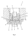
- FIG. 1 1 shows a device 1 for producing elastomer products 2.
- the device essentially comprises a molding tool 3 with at least one cavity 4 for the elastomer product 2 to be produced and a nozzle unit 5 arranged above the molding tool 3.
- the nozzle unit 5 has for transporting the raw material into the cavity 4 of the mold 3 a Ring unit 6 on.
- This consists of a concentric central region 11 through which the raw material is fed axially from above or below the nozzle unit 5.
- a plurality of channels 12 extend radially outward, with the channels 12 terminating directly on the forming tool 3. Via the channels 12, the raw material is supplied from the central region 11 to the mold 3 and flows through it into the cavity 4.
- the nozzle unit 5 is arranged movably relative to the mold 3, the nozzle unit 5 being hydraulically movable axially relative to the mold 3,
- the nozzle unit 5 is provided with a cooling device 7.
- the nozzle unit 5 has a separate annular cover 10, wherein the nozzle unit 5 forms part of the wall of the ring unit 6 and the cover 10 forms a further part of the wall of the ring unit 6.
- the nozzle unit 5 and the cover 10 are axially movable relative to each other.
- the mold 3 is also formed in two parts in order to remove the elastomer product 2 from the cavity 4 can. Both parts of the molding tool 3 define a gap 13 through which the raw material of the cavity 4 is supplied. Due to the axial mobility of nozzle unit 5 and cover 10 deviations of the gap thickness of the gap 13 can be compensated.
- the raw material of the elastomer product 2 to be produced is fed via the nozzle unit 5 to the cavity 4 of the mold 3 and the nozzle unit 5 is thermally separated from the mold 3 after completion of the feed of the raw material into the cavity 4 ,
- the nozzle unit 5 is spaced from the mold 3 before the start of the supply of raw material, applied to the mold 3 for supplying the raw material and again spaced from the mold 3 after completion of the supply of the raw material.
- the device 1 according to the invention and the method according to the invention are particularly advantageous for producing sealing rings. Depending on the application of the seal, it may be necessary to select high-priced materials.
- One such high-priced and commonly used material is FKM (fluororubber).
- FKM fluororubber
- the device according to the invention and the method according to the invention result in high material and cost savings. Furthermore, reduces the amount of waste to be disposed sprue.
- FIG. 2 shows a device 1 for producing elastomer products 2 according to FIG. 1 ,
- the device 1 is designed so that annular vulcanized elastomer products 2, here sealing rings are produced.
- the nozzle unit 5 is provided with a cooling device 7.
- the cooling device 7 has a heat-dissipating plate 8, which is arranged on the underside of the nozzle unit 5 and faces the mold 3.
- the heat-dissipating plate 8 is disposed between the mold 3 and the nozzle unit 5.
- the cooling device 7 has a plurality of heat-dissipating devices 9, which are formed in this embodiment as a heat pipe.
- the devices 9 extend into the nozzle unit 5 and carry off the heat stored in the cooling device 7 into regions of the nozzle unit 5 that do not influence the ring unit 6.
Landscapes
- Engineering & Computer Science (AREA)
- Manufacturing & Machinery (AREA)
- Mechanical Engineering (AREA)
- Moulds For Moulding Plastics Or The Like (AREA)
- Injection Moulding Of Plastics Or The Like (AREA)
Abstract
Description
- Die Erfindung betrifft eine Vorrichtung zum Herstellen von Elastomerprodukten, umfassend ein Formwerkzeug mit zumindest einer Kavität für das herzustellende Elastomerprodukt und einer Düseneinheit und ein Verfahren zur Herstellung von Elastomerprodukten.
- Es gibt Elastomerprodukte in verschiedensten Ausprägungen. Eine bekannte Gattung ringförmiger Elastomerprodukte sind Dichtungsringe, mit Dichtlippen aus elastomerem Werkstoff in verschiedensten Formgebungen. Den Elastomerprodukten ist gemeinsam, dass die Formgebung in der Kavität eines Formwerkzeugs erfolgt, der das Rohmaterial des Elastomerproduktes beispielsweise mittels Spritzgießen zugeführt wird. Des Weiteren erfolgt eine Vulkanisation des Elastomerproduktes, also eine Wärmebehandlung noch innerhalb der Kavität. Elastomere Werkstoffe, die einmal durch eine Wärmbehandlung vulkanisiert werden, können anschließend nicht mehr durch Urformen geformt werden. Daher ist es erforderlich, die Düseneinheit einer Spritzgießmaschine zu kühlen, um zu verhindern, dass das Elastomermaterial bereits in der Düseneinheit vulkanisiert. Dazu sind aus dem Stand der Technik verschiedene Ausführungen von Kaltkanälen bekannt, bei denen die Kanäle durch die das Rohmaterial strömt gekühlt werden. Ringförmige vulkanisierte Elastomerprodukte werden momentan im Spritzguss derart hergestellt, dass eine zentrale temperierte Düse das Rohmaterial der Kavität zuführt. Dabei entsteht, der Mitte des ringförmigen Elastomerproduktes zugeordnet, eine Scheibe mit einem koaxialen Anguss, die durch ein geeignetes Trennverfahren von dem Elastomerprodukt entfernt werden muss. Dabei entsteht eine Abfallmenge, die die Menge des Elastomerproduktes übersteigen kann. Der scheibenförmige Anguss ist vulkanisiert und kann nicht wiederverwertet oder weiterbearbeitet werden.
- Der Erfindung liegt die Aufgabe zugrunde, eine Vorrichtung und ein Verfahren zur Herstellung ringförmiger vulkanisierter Elastomerprodukte bereitzustellen, bei der die Abfallmenge ausvulkanisierten Rohmaterials reduziert ist.
- Diese Aufgabe wird mit den Merkmalen von Anspruch 1 und 11 gelöst. Auf vorteilhafte Ausgestaltungen nehmen die Unteransprüche Bezug.
- Zur Lösung der Aufgabe weist die Düseneinheit der Vorrichtung eine Ringeinheit auf. Die Ringeinheit umfasst einen konzentrischen Zentralbereich durch den das Rohmaterial axial von oben oder unten der Düseneinheit zugeführt wird. Ausgehend von dem Zentralbereich erstrecken sich mehrere Kanäle radial nach außen. Mittels strömungstechnisch günstigem Übergang wird das Material von den Kanälen aber eine Ringeinheit dem Formwerkzeug zugeführt. Dabei ist die Düseneinheit so ausgebildet, dass das Rohmaterial in dem Zentralbereich, in den Kanälen und in der Ringeinheit stets formbar bleibt und nicht vulkanisiert. Der Vulkanisationsprozess findet ausschließlich in dem Formwerkzeug durch eine geeignete Wärmebehandlung statt. Das Elastomerprodukt, weiches in der erfindungsgemäßen Vorrichtung hergestellt wird, weist dabei einen ringförmigen Anguss auf, der anschließend in einer nachgeschalteten Bearbeitung entfernt wird. Der Vorteil des ringförmigen Angusses im Vergleich zu dem bekannten scheibenförmigen Anguss aus dem Stand der Technik liegt insbesondere in der Materialersparnis. Durch die erfindungsgemäße Vorrichtung können je Elastomerprodukt weit mehr als 50% Rohmaterial eingespart werden.
- Die Düseneinheit kann beweglich zu dem Formwerkzeug angeordnet sein. Hierbei ist vorteilhaft, dass die Düseneinheit nur temporär, nämlich während des Gießvorgangs an dem Formwerkzeug anliegt und dann über die Ringeinheit der Kavität das Material zuführt. Die Düseneinheit ist dabei derart temperiert, dass das in der Düseneinheit vorhandene Rohmaterial stets formbar bleibt unabhängig von der Temperierung des Formwerkzeuges. Dabei sind die Düseneinheit und die Ringeinheit vorzugsweise axial zu dem Formwerkzeug beweglich. Nach Abschluss des Gießvorganges werden die Düseneinheit und die Ringeinheit axial nach oben von dem Formwerkzeug weggeführt, Damit sind die Düseneinheit und die Ringeinheit von dem Formwerkzeug beabstandet und das Rohmaterial wird in der Kavität des Formwerkzeugs wärmebehandelt, so dass es vulkanisiert und das Elastomerprodukt und einen Teil des Elastomerproduktes bildet.
- Die Düseneinheit kann mit einer Kühleinrichtung versehen sein. Die Kühleinrichtung ist dabei vorzugsweise ein Material mit hoher Wärmeleitfähigkeit, so dass die Kühleinrichtung die von der Düseneinheit abzuführende Wärme schnell ableitet. Des Weiteren ist die Kühleinrichtung vorzugsweise dem Formwerkzeug zugewandt, da der Düseneinheit in diesem Bereich der Wärme des Formwerkzeugs ausgesetzt ist. Diese Wärme kann durch die Kühleinrichtung abgeführt werden.
- Die Kühleinrichtung kann eine wärmeableitende Platte aufweisen. Die wärmeableitende Platte bedeckt die Unterseite der Düseneinheit flächig und verbessert so die Wärmeabfuhr.
- Die Kühleinrichtung kann wärmeableitende Einrichtungen aufweisen. Die wärmeableitenden Einrichtungen führen die durch die Kühleinrichtung aufgenommene Wärme von der Ringeinheit weg. Dabei können sich die Einrichtungen in die Düseneinheit hinein erstrecken. Vorteilhafterweise erstrecken sich die Einrichtungen dabei in Abschnitte der Düseneinheit die zum einen von der Ringeinheit so beabstandet sind, dass die Abschnitte wiederum nicht zu einer Erwärmung der Ringeinheit führen und zum anderen die Abschnitte eine derartige Masse aufweisen, dass die Wärmekapazität groß ist.
- Die Einrichtungen können als Heatpipes ausgebildet sein. Eine Heatpipe, auch als Wärmerohr bezeichnet ist ein Wärmeüberträger, der unter Nutzung von Verdampfungswärme eines Stoffes eine hohe Wärmestromdichte erlaubt, so können auf kleiner Querschnittsfläche große Mengen Wärme transportiert werden. Dadurch kann die durch die Kühleinrichtung aufgenommene Wärme sehr effektiv in andere Bereiche der Düseneinheit übertragen werden.
- Die Düseneinheit kann eine separate ringförmige Abdeckung aufweisen, wobei die Düseneinheit einen Teil der Wandung der Ringeinheit bildet und die Abdeckung einen weiteren Teil der Wandung der Ringeinheit bildet. Dabei können die Düseneinheit und die Abdeckung zueinander axial beweglich ausgebildet sein. Um das Elastomerprodukt aus dem Formwerkzeug entformen zu können, ist das Formwerkzeug mehrteilig, wenigstens zweiteilig ausgebildet und im Bereich des Angusses befindet sich ein Spalt. Durch diesen Spalt wird das Rohmaterial aus der Düseneinheit der Kavität des Formwerkzeugs zugeführt. Bedingt durch die Mehrteiligkeit des Formwerkzeugs kann die Spaltbreite des Spaltes in Grenzen variieren. Dies würde jedoch zu Undichtigkeiten und zu fehlerhaftem Materialfluss führen. Durch die Beweglichkeit von Düseneinheit und Abdeckung zueinander kann die Abweichung der Spaltbreite kompensiert werden, so dass die Ringeinheit stets dicht an dem Formwerkzeug anliegt.
- Zur Lösung der Aufgabe wird bei dem erfindungsgemäßen Verfahren das Rohmaterial des herzustellenden Elastomerproduktes über eine Düseneinheit einer Kavität eines Formwerkzeuges zugeführt, wobei die Düseneinheit nach Abschluss der Zufuhr des Rohmaterials in die Kavität thermisch von dem Formwerkzeug getrennt wird. Dadurch ist das in der Düseneinheit enthaltene Rohmaterial unbeeinflusst von der nachfolgenden Wärmebehandlung in dem Formwerkzeug und bleibt für nachfolgende Arbeitsschritte formbar. Dabei kann die Düseneinheit vor Beginn der Zufuhr des Rohmaterials von dem Formwerkzeug beabstandet werden, zur Zufuhr des Rohmaterials an das Formwerkzeug angelegt werden und nach Abschluss der Zufuhr des Rohmaterials wieder von dem Formwerkzeug beabstandet werden. Somit berührt die Düseneinheit das Formwerkzeug nur während der Zufuhr des Rohmaterials und ist ansonsten von thermischen Einflüssen des Formwerkzeugs isoliert.
- Eine Ausführung der erfindungsgemäßen Vorrichtung wird nachfolgend anhand der Figur näher erläutert. Diese zeigt schematisch:
- Fig. 1
- eine Vorrichtung im Schnitt;
- Fig. 2
- eine Vorrichtung zum Herstellen von Dichtungsringen.
-
Figur 1 zeigt eine Vorrichtung 1 zum Herstellen von Elastomerprodukten 2. Die Vorrichtung umfasst im Wesentlichen ein Formwerkzeug 3 mit zumindest einer Kavität 4 für das herzustellende Elastomerprodukt 2 und einer oberhalb des Formwerkzeugs 3 angeordneten Düseneinheit 5. Die Düseneinheit 5 weist zum Transport des Rohmaterials in die Kavität 4 des Formwerkzeugs 3 eine Ringeinheit 6 auf. Diese besteht aus einem konzentrischen Zentralbereich 11 durch den das Rohmaterial axial von oben oder unten der Düseneinheit 5 zugeführt wird. Ausgehend von dem Zentralbereich 11 erstrecken sich mehrere Kanäle 12 radial nach außen, wobei die Kanäle 12 direkt an dem Formwerkzeig 3 enden. Über die Kanäle 12 wird das Rohmaterial ausgehend von dem Zentralbereich 11 dem Formwerkzeug 3 zugeführt und strömt durch diese in die Kavität 4. Dabei ist die Düseneinheit 5 beweglich zu dem Formwerkzeug 3 angeordnet, wobei die Düseneinheit 5 hydraulisch axial zu dem Formwerkzeug 3 beweglich ist, Die Düseneinheit 5 ist mit einer Kühleinrichtung 7 versehen. Die Düseneinheit 5 weist eine separate ringförmige Abdeckung 10 auf, wobei die Düseneinheit 5 einen Teil der Wandung der Ringeinheit 6 bildet und die Abdeckung 10 einen weiteren Teil der Wandung der Ringeinheit 6 bildet. Dabei sind die Düseneinheit 5 und die Abdeckung 10 zueinander axial beweglich ausgebildet. Das Formwerkzeug 3 ist ebenfalls zweiteilig ausgebildet, um das Elastomerprodukt 2 aus der Kavität 4 entformen zu können. Beide Teile des Formwerkzeuges 3 begrenzen dabei einen Spalt 13 durch den das Rohmaterial der Kavität 4 zugeführt wird. Durch die axiale Beweglichkeit von Düseneinheit 5 und Abdeckung 10 können Abweichungen der Spaltdicke des Spaltes 13 kompensiert werden. - In dem erfindungsgemäßen Verfahren zur Herstellung eines ringförmigen vulkanisierten Elastomerproduktes 2, wird das Rohmaterial des herzustellenden Elastomerproduktes 2 über die Düseneinheit 5 der Kavität 4 des Formwerkzeuges 3 zugeführt und die Düseneinheit 5 nach Abschluss der Zufuhr des Rohmaterials in die Kavität 4 thermisch von dem Formwerkzeug 3 getrennt. Dazu wird die Düseneinheit 5 vor Beginn der Zufuhr des Rohmaterials von dem Formwerkzeug 3 beabstandet, zur Zufuhr des Rohmaterials an das Formwerkzeug 3 angelegt und nach Abschluss der Zufuhr des Rohmaterials wieder von dem Formwerkzeug 3 beabstandet.
- Die erfindungsgemäße Vorrichtung 1 und das erfindungsgemäße Verfahren eignen sich besonders vorteilhaft zum Herstellen von Dichtungsringen. Je nach Anwendung der Dichtung kann es erforderlich sein, hochpreisige Werkstoffe auszuwählen. Ein derartiger hochpreisiger und häufig verwendeter Werkstoff ist FKM (Fluorkautschuk). Durch die erfindungsgemäße Vorrichtung und das erfindungsgemäße Verfahren ergeben sich dabei hohe Material- und Kostenersparnisse. Des Weiteren reduziert sich die Abfallmenge des zu entsorgenden Angusses.
-
Figur 2 zeigt eine Vorrichtung 1 zum Herstellen von Elastomerprodukten 2 gemäßFigur 1 . Dabei ist die Vorrichtung 1 so ausgebildet, dass ringförmige vulkanisierte Elastomerprodukte 2, hier Dichtungsringe hergestellt werden. Die Düseneinheit 5 ist mit einer Kühleinrichtung 7 versehen. Dazu weist die Kühleinrichtung 7 eine wärmeableitende Platte 8 auf, die an der Unterseite der Düseneinheit 5 angeordnet und dem Formwerkzeug 3 zugewandt ist. Somit ist die wärmeableitende Platte 8 zwischen Formwerkzeug 3 und Düseneinheit 5 angeordnet. Zur Abfuhr der in der Kühleinrichtung 7 gespeicherten Wärme weist die Kühleinrichtung 7 mehrere wärmeableitende Einrichtungen 9 auf, die in dieser Ausgestaltung als Heatpipe ausgebildet sind. Die Einrichtungen 9 erstrecken sich in die Düseneinheit 5 hinein und führen die in der Kühleinrichtung 7 gespeicherten Wärme in Bereiche der Düseneinheit 5 ab, die die Ringeinheit 6 nicht beeinflussen.
Claims (12)
- Vorrichtung (1) zum Herstellen ringförmiger vulkanisierter Elastomerprodukte (2), umfassend ein Formwerkzeug (3) mit zumindest einer Kavität (4) für das herzustellende Elastomerprodukt (2) und einer Düseneinheit (5), dadurch gekennzeichnet, dass die Düseneinheit (5) eine Ringeinheit (6) aufweist.
- Vorrichtung nach Anspruch 1, dadurch gekennzeichnet, dass die Düseneinheit (5) beweglich zu dem Formwerkzeug (3) angeordnet ist.
- Vorrichtung nach Anspruch 2, dadurch gekennzeichnet, dass die Düseneinheit (5) axial zu dem Formwerkzeug (3) beweglich ist.
- Vorrichtung nach einem der Ansprüche 1 bis 3, dadurch gekennzeichnet, dass die Düseneinheit (5) mit einer Kühleinrichtung (7) versehen ist.
- Vorrichtung nach Anspruch 4, dadurch gekennzeichnet, dass die Kühleinrichtung (7) eine wärmeableitende Platte (8) aufweist.
- Vorrichtung nach Anspruch 4 oder 5, dadurch gekennzeichnet, dass die Kühleinrichtung (7) wärmeableitende Einrichtungen (9) aufweist.
- Vorrichtung nach Anspruch 6, dadurch gekennzeichnet, dass sich die Einrichtungen (9) in die Düseneinheit (5) hinein erstrecken.
- Vorrichtung nach Anspruch 6 oder 7, dadurch gekennzeichnet, dass die Einrichtungen (9) als Heatpipes ausgebildet sind,
- Vorrichtung nach einem der Ansprüche 1 bis 8, dadurch gekennzeichnet, dass die Düseneinheit (5) eine separate ringförmige Abdeckung (10) aufweist, wobei die Düseneinheit (5) einen Teil der Wandung der Ringeinheit (6) bildet und die Abdeckung (10) einen weiteren Teil der Wandung der Ringeinheit (6) bildet.
- Vorrichtung nach Anspruch 9, dadurch gekennzeichnet, dass die Düseneinheit (5) und die Abdeckung (10) zueinander axial beweglich ausgebildet sind.
- Verfahren zur Herstellung eines ringförmigen vulkanisierten Elastomerproduktes (2), wobei das Rohmaterial des herzustellenden Elastomerproduktes (2) über wenigstens eine Düseneinheit (5) wenigstens einer Kavität (4) eines Formwerkzeuges (3) zugeführt wird, dadurch gekennzeichnet, dass die Düseneinheit (5) nach Abschluss der Zufuhr des Rohmaterials in die Kavität (4) thermisch von dem Formwerkzeug (3) getrennt wird.
- Verfahren nach Anspruch 11, dadurch gekennzeichnet, dass die Düseneinheit (5) vor Beginn der Zufuhr des Rohmaterials von dem Formwerkzeug (3) beabstandet wird, zur Zufuhr des Rohmaterials an das Formwerkzeug (3) angelegt wird und nach Abschluss der Zufuhr des Rohmaterials wieder von dem Formwerkzeug (3) beabstandet wird.
Priority Applications (6)
| Application Number | Priority Date | Filing Date | Title |
|---|---|---|---|
| EP09013862.9A EP2319676B1 (de) | 2009-11-04 | 2009-11-04 | Vorrichtung zum Herstellung von Elastomerprodukten |
| JP2010194388A JP2011098564A (ja) | 2009-11-04 | 2010-08-31 | エラストマー製品の製造装置及びエラストマー製品の製造方法 |
| CN2010105261033A CN102049839A (zh) | 2009-11-04 | 2010-10-27 | 用于制造弹性体产品的装置 |
| MX2010011888A MX2010011888A (es) | 2009-11-04 | 2010-10-29 | Dispositivo para producir productos elastomeros. |
| RU2010145122/05A RU2455160C1 (ru) | 2009-11-04 | 2010-11-03 | Устройство для изготовления эластомерных изделий |
| BRPI1004703-4A BRPI1004703B1 (pt) | 2009-11-04 | 2010-11-03 | dispositivo para a fabricação de produtos anelares de elastômero vulcanizados |
Applications Claiming Priority (1)
| Application Number | Priority Date | Filing Date | Title |
|---|---|---|---|
| EP09013862.9A EP2319676B1 (de) | 2009-11-04 | 2009-11-04 | Vorrichtung zum Herstellung von Elastomerprodukten |
Publications (2)
| Publication Number | Publication Date |
|---|---|
| EP2319676A1 true EP2319676A1 (de) | 2011-05-11 |
| EP2319676B1 EP2319676B1 (de) | 2016-10-05 |
Family
ID=42075836
Family Applications (1)
| Application Number | Title | Priority Date | Filing Date |
|---|---|---|---|
| EP09013862.9A Not-in-force EP2319676B1 (de) | 2009-11-04 | 2009-11-04 | Vorrichtung zum Herstellung von Elastomerprodukten |
Country Status (6)
| Country | Link |
|---|---|
| EP (1) | EP2319676B1 (de) |
| JP (1) | JP2011098564A (de) |
| CN (1) | CN102049839A (de) |
| BR (1) | BRPI1004703B1 (de) |
| MX (1) | MX2010011888A (de) |
| RU (1) | RU2455160C1 (de) |
Cited By (1)
| Publication number | Priority date | Publication date | Assignee | Title |
|---|---|---|---|---|
| WO2024038173A1 (de) * | 2022-08-19 | 2024-02-22 | Elringklinger Ag | Verfahren und gusswerkzeug zur herstellung eines dichtelements, dichtelement |
Families Citing this family (2)
| Publication number | Priority date | Publication date | Assignee | Title |
|---|---|---|---|---|
| CA3042742C (en) * | 2016-12-01 | 2023-05-09 | Husky Injection Molding Systems Ltd. | Channel geometry for promoting at least one of a uniform velocity profile and a uniform temperature profile for an annular or part-annular melt flow |
| JP7208958B2 (ja) * | 2020-09-28 | 2023-01-19 | 三菱電線工業株式会社 | エラストマー成形品の製造方法及びそれに用いる成形用型 |
Citations (16)
| Publication number | Priority date | Publication date | Assignee | Title |
|---|---|---|---|---|
| DE2133824A1 (de) * | 1971-07-07 | 1973-02-01 | Pfannenberg Gmbh Eisen U Metal | Spritzgussform fuer die herstellung von kunststoffspritzteilen |
| US3754846A (en) * | 1972-01-21 | 1973-08-28 | Cpi Inc | Apparatus for single cavity injection molding of oil seals |
| US3936257A (en) * | 1971-06-22 | 1976-02-03 | Chicago Rawhide Manufacturing Company | Closed stroke molding |
| US3993787A (en) * | 1974-11-14 | 1976-11-23 | Nippon Oil Seal Industry Co., Ltd. | Rotary molder |
| EP0013119A1 (de) * | 1978-12-21 | 1980-07-09 | Occidental Chemical Corporation | Vorrichtung zum angusslosen Spritzpressgiessen wärmehärtbarer Materialien |
| DE3032814A1 (de) * | 1980-08-30 | 1982-04-22 | Kunststoff-Maschinen-Handelsgesellschaft mbH, 4990 Lübbecke | Vorrichtung zum spritzpressen haertbarer formmassen |
| JPS6140129A (ja) * | 1984-07-31 | 1986-02-26 | Dainichi Nippon Cables Ltd | シ−ルリング射出成形法 |
| EP0243875A2 (de) * | 1986-04-24 | 1987-11-04 | Reinhold Langbein | Verfahren sowie Spritzgusswerkzeug zur Herstellung eines Rotors für Elektromotoren |
| JPS636821U (de) * | 1986-06-27 | 1988-01-18 | ||
| DE3643833A1 (de) * | 1986-12-20 | 1988-06-30 | Lechler Elring Dichtungswerke | Duesenanordnung zum spritzgiessen oder spritzpressen ringfoermiger gegenstaende |
| DE4414005A1 (de) * | 1993-04-22 | 1994-11-10 | Hinterlechner Gerhard | Verfahren zum Ummanteln von elektronischen Bauteilen |
| JPH0970853A (ja) * | 1995-09-04 | 1997-03-18 | Sato Tekkosho:Kk | スプルー、ランナーを内蔵する射出成形機 |
| GB2322589A (en) * | 1997-02-28 | 1998-09-02 | Patrick Arthur Leach | Moulding loudspeaker cone surround assembly |
| JP2000326361A (ja) * | 1999-05-20 | 2000-11-28 | Matsushita Electric Ind Co Ltd | 射出成形用金型 |
| US20040247738A1 (en) * | 2002-06-04 | 2004-12-09 | Yoshiaki Tanaka | Device and method for runner-less molding of thermosetting resin and rubber |
| JP2008055614A (ja) * | 2006-08-29 | 2008-03-13 | Bridgestone Corp | 射出成形機 |
Family Cites Families (3)
| Publication number | Priority date | Publication date | Assignee | Title |
|---|---|---|---|---|
| JPS5535253B2 (de) * | 1974-06-14 | 1980-09-12 | ||
| SU1090579A1 (ru) * | 1982-12-28 | 1984-05-07 | Предприятие П/Я Р-6799 | Пресс-форма дл изготовлени кольцевых резиновых изделий |
| JP2600215Y2 (ja) * | 1993-03-31 | 1999-10-04 | 株式会社松田製作所 | 射出成形機におけるノズルの温調装置 |
-
2009
- 2009-11-04 EP EP09013862.9A patent/EP2319676B1/de not_active Not-in-force
-
2010
- 2010-08-31 JP JP2010194388A patent/JP2011098564A/ja active Pending
- 2010-10-27 CN CN2010105261033A patent/CN102049839A/zh active Pending
- 2010-10-29 MX MX2010011888A patent/MX2010011888A/es active IP Right Grant
- 2010-11-03 BR BRPI1004703-4A patent/BRPI1004703B1/pt not_active IP Right Cessation
- 2010-11-03 RU RU2010145122/05A patent/RU2455160C1/ru active
Patent Citations (17)
| Publication number | Priority date | Publication date | Assignee | Title |
|---|---|---|---|---|
| US3936257A (en) * | 1971-06-22 | 1976-02-03 | Chicago Rawhide Manufacturing Company | Closed stroke molding |
| US3936257B1 (de) * | 1971-06-22 | 1984-07-24 | ||
| DE2133824A1 (de) * | 1971-07-07 | 1973-02-01 | Pfannenberg Gmbh Eisen U Metal | Spritzgussform fuer die herstellung von kunststoffspritzteilen |
| US3754846A (en) * | 1972-01-21 | 1973-08-28 | Cpi Inc | Apparatus for single cavity injection molding of oil seals |
| US3993787A (en) * | 1974-11-14 | 1976-11-23 | Nippon Oil Seal Industry Co., Ltd. | Rotary molder |
| EP0013119A1 (de) * | 1978-12-21 | 1980-07-09 | Occidental Chemical Corporation | Vorrichtung zum angusslosen Spritzpressgiessen wärmehärtbarer Materialien |
| DE3032814A1 (de) * | 1980-08-30 | 1982-04-22 | Kunststoff-Maschinen-Handelsgesellschaft mbH, 4990 Lübbecke | Vorrichtung zum spritzpressen haertbarer formmassen |
| JPS6140129A (ja) * | 1984-07-31 | 1986-02-26 | Dainichi Nippon Cables Ltd | シ−ルリング射出成形法 |
| EP0243875A2 (de) * | 1986-04-24 | 1987-11-04 | Reinhold Langbein | Verfahren sowie Spritzgusswerkzeug zur Herstellung eines Rotors für Elektromotoren |
| JPS636821U (de) * | 1986-06-27 | 1988-01-18 | ||
| DE3643833A1 (de) * | 1986-12-20 | 1988-06-30 | Lechler Elring Dichtungswerke | Duesenanordnung zum spritzgiessen oder spritzpressen ringfoermiger gegenstaende |
| DE4414005A1 (de) * | 1993-04-22 | 1994-11-10 | Hinterlechner Gerhard | Verfahren zum Ummanteln von elektronischen Bauteilen |
| JPH0970853A (ja) * | 1995-09-04 | 1997-03-18 | Sato Tekkosho:Kk | スプルー、ランナーを内蔵する射出成形機 |
| GB2322589A (en) * | 1997-02-28 | 1998-09-02 | Patrick Arthur Leach | Moulding loudspeaker cone surround assembly |
| JP2000326361A (ja) * | 1999-05-20 | 2000-11-28 | Matsushita Electric Ind Co Ltd | 射出成形用金型 |
| US20040247738A1 (en) * | 2002-06-04 | 2004-12-09 | Yoshiaki Tanaka | Device and method for runner-less molding of thermosetting resin and rubber |
| JP2008055614A (ja) * | 2006-08-29 | 2008-03-13 | Bridgestone Corp | 射出成形機 |
Non-Patent Citations (1)
| Title |
|---|
| DATABASE WPI Week 199721, Derwent World Patents Index; AN 1997-230530, XP002591343 * |
Cited By (1)
| Publication number | Priority date | Publication date | Assignee | Title |
|---|---|---|---|---|
| WO2024038173A1 (de) * | 2022-08-19 | 2024-02-22 | Elringklinger Ag | Verfahren und gusswerkzeug zur herstellung eines dichtelements, dichtelement |
Also Published As
| Publication number | Publication date |
|---|---|
| CN102049839A (zh) | 2011-05-11 |
| JP2011098564A (ja) | 2011-05-19 |
| BRPI1004703B1 (pt) | 2020-01-28 |
| MX2010011888A (es) | 2011-05-19 |
| RU2455160C1 (ru) | 2012-07-10 |
| BRPI1004703A2 (pt) | 2013-02-26 |
| RU2010145122A (ru) | 2012-05-10 |
| EP2319676B1 (de) | 2016-10-05 |
Similar Documents
| Publication | Publication Date | Title |
|---|---|---|
| DE2657551C3 (de) | Vorrichtung zur Herstellung von Guß mit gerichtetem Gefuge | |
| DE102014103532A1 (de) | Druckgusswerkzeug zum Gießen einer Tragstruktur eines Ölfiltermoduls für eine Brennkraftmaschine | |
| DE102004017276B4 (de) | Spritzgießvorrichtung mit frontseitig montierbarer Düse mit einem seitlichen Anguss | |
| EP2319676B1 (de) | Vorrichtung zum Herstellung von Elastomerprodukten | |
| EP2945760A1 (de) | VERFAHREN UND GIEßFORM ZUR HERSTELLUNG VON GUSSTEILEN, INSBESONDERE ZYLINDERBLÖCKEN UND ZYLINDERKÖPFEN, MIT FUNKTIONALER ANBINDUNG DES SPEISERS | |
| DE102013003550A1 (de) | Ventilnadelbuchse für eine Spritzgießvorrichtung | |
| EP2303539A2 (de) | Spritzgiessdüse für ein spritzgiesswerkzeug | |
| DE102015112223A1 (de) | Spritzgießform mit Kernring | |
| DE69209748T2 (de) | Selbstklemmende Formzusammenbauten | |
| DE19813105A1 (de) | Verfahren zur Herstellung von Faserverbundbauteilen | |
| EP2015917B1 (de) | Bodeneinsatz mit wärmeisolation | |
| DE102006021228A1 (de) | Zweiteiliger Bodeneinsatz | |
| DE102017113885A1 (de) | Verteilereinrichtung für eine Spritzgießdüse, Spritzgießdüse mit Verteilereinrichtung und Spritzgießwerkzeug mit Spritzgießdüse und Verteilereinrichtung | |
| DE102012208677B4 (de) | Verfahren und Vorrichtung zum Temperieren von plastischer Kunststoffmasse | |
| DE102007043386B4 (de) | Kokille zum Stranggießen von Metall und Verfahren zum Herstellen einer derartigen Kokille | |
| EP2069124B1 (de) | Übergabeelement, insbesondere für eine dekompressions-angussbuchse oder eine dekompressions-maschinendüse | |
| DE9110897U1 (de) | Spritzgießvorrichtung | |
| DE102015206966A1 (de) | Getriebeteil aus Kunststoff | |
| DE102024123445B3 (de) | Spritzgießmaschine, Silikon-Spritzgießadapter und Verfahren zum Spritzgießen von Silikonwerkstücken | |
| DE202015005162U1 (de) | Angussbuchse | |
| DE60318008T2 (de) | Verfahren und Vorrichtung zur diskontinuierlichen Herstellung von Rohrverbindungen mit geringem Verzug | |
| DE1583681A1 (de) | Verfahren und Vorrichtung zum Steuern der Temperatur von Giessformteilen | |
| DE102022123011A1 (de) | Verfahren zur Herstellung einer Statoreinrichtung für eine elektrische Maschine, insbesondere für eine Antriebsmaschine eines Elektrofahrzeugs | |
| DE102024111039A1 (de) | Spritzgießwerkzeugplatte und Verwendung eines Halteelements dafür | |
| WO2021163740A1 (de) | Verfahren zur herstellung eines metallischen bauteiles und vorrichtung hierzu |
Legal Events
| Date | Code | Title | Description |
|---|---|---|---|
| PUAI | Public reference made under article 153(3) epc to a published international application that has entered the european phase |
Free format text: ORIGINAL CODE: 0009012 |
|
| AK | Designated contracting states |
Kind code of ref document: A1 Designated state(s): AT BE BG CH CY CZ DE DK EE ES FI FR GB GR HR HU IE IS IT LI LT LU LV MC MK MT NL NO PL PT RO SE SI SK SM TR |
|
| AX | Request for extension of the european patent |
Extension state: AL BA RS |
|
| 17P | Request for examination filed |
Effective date: 20110512 |
|
| 17Q | First examination report despatched |
Effective date: 20120702 |
|
| GRAP | Despatch of communication of intention to grant a patent |
Free format text: ORIGINAL CODE: EPIDOSNIGR1 |
|
| INTG | Intention to grant announced |
Effective date: 20160504 |
|
| GRAS | Grant fee paid |
Free format text: ORIGINAL CODE: EPIDOSNIGR3 |
|
| GRAA | (expected) grant |
Free format text: ORIGINAL CODE: 0009210 |
|
| AK | Designated contracting states |
Kind code of ref document: B1 Designated state(s): AT BE BG CH CY CZ DE DK EE ES FI FR GB GR HR HU IE IS IT LI LT LU LV MC MK MT NL NO PL PT RO SE SI SK SM TR |
|
| REG | Reference to a national code |
Ref country code: GB Ref legal event code: FG4D Free format text: NOT ENGLISH |
|
| REG | Reference to a national code |
Ref country code: CH Ref legal event code: EP |
|
| REG | Reference to a national code |
Ref country code: AT Ref legal event code: REF Ref document number: 834227 Country of ref document: AT Kind code of ref document: T Effective date: 20161015 |
|
| REG | Reference to a national code |
Ref country code: IE Ref legal event code: FG4D Free format text: LANGUAGE OF EP DOCUMENT: GERMAN |
|
| REG | Reference to a national code |
Ref country code: DE Ref legal event code: R096 Ref document number: 502009013160 Country of ref document: DE |
|
| REG | Reference to a national code |
Ref country code: NL Ref legal event code: MP Effective date: 20161005 |
|
| REG | Reference to a national code |
Ref country code: LT Ref legal event code: MG4D |
|
| PG25 | Lapsed in a contracting state [announced via postgrant information from national office to epo] |
Ref country code: BE Free format text: LAPSE BECAUSE OF NON-PAYMENT OF DUE FEES Effective date: 20161130 Ref country code: LV Free format text: LAPSE BECAUSE OF FAILURE TO SUBMIT A TRANSLATION OF THE DESCRIPTION OR TO PAY THE FEE WITHIN THE PRESCRIBED TIME-LIMIT Effective date: 20161005 |
|
| PG25 | Lapsed in a contracting state [announced via postgrant information from national office to epo] |
Ref country code: SE Free format text: LAPSE BECAUSE OF FAILURE TO SUBMIT A TRANSLATION OF THE DESCRIPTION OR TO PAY THE FEE WITHIN THE PRESCRIBED TIME-LIMIT Effective date: 20161005 Ref country code: NO Free format text: LAPSE BECAUSE OF FAILURE TO SUBMIT A TRANSLATION OF THE DESCRIPTION OR TO PAY THE FEE WITHIN THE PRESCRIBED TIME-LIMIT Effective date: 20170105 Ref country code: GR Free format text: LAPSE BECAUSE OF FAILURE TO SUBMIT A TRANSLATION OF THE DESCRIPTION OR TO PAY THE FEE WITHIN THE PRESCRIBED TIME-LIMIT Effective date: 20170106 Ref country code: LT Free format text: LAPSE BECAUSE OF FAILURE TO SUBMIT A TRANSLATION OF THE DESCRIPTION OR TO PAY THE FEE WITHIN THE PRESCRIBED TIME-LIMIT Effective date: 20161005 |
|
| PG25 | Lapsed in a contracting state [announced via postgrant information from national office to epo] |
Ref country code: HR Free format text: LAPSE BECAUSE OF FAILURE TO SUBMIT A TRANSLATION OF THE DESCRIPTION OR TO PAY THE FEE WITHIN THE PRESCRIBED TIME-LIMIT Effective date: 20161005 Ref country code: PL Free format text: LAPSE BECAUSE OF FAILURE TO SUBMIT A TRANSLATION OF THE DESCRIPTION OR TO PAY THE FEE WITHIN THE PRESCRIBED TIME-LIMIT Effective date: 20161005 Ref country code: FI Free format text: LAPSE BECAUSE OF FAILURE TO SUBMIT A TRANSLATION OF THE DESCRIPTION OR TO PAY THE FEE WITHIN THE PRESCRIBED TIME-LIMIT Effective date: 20161005 Ref country code: PT Free format text: LAPSE BECAUSE OF FAILURE TO SUBMIT A TRANSLATION OF THE DESCRIPTION OR TO PAY THE FEE WITHIN THE PRESCRIBED TIME-LIMIT Effective date: 20170206 Ref country code: ES Free format text: LAPSE BECAUSE OF FAILURE TO SUBMIT A TRANSLATION OF THE DESCRIPTION OR TO PAY THE FEE WITHIN THE PRESCRIBED TIME-LIMIT Effective date: 20161005 Ref country code: IS Free format text: LAPSE BECAUSE OF FAILURE TO SUBMIT A TRANSLATION OF THE DESCRIPTION OR TO PAY THE FEE WITHIN THE PRESCRIBED TIME-LIMIT Effective date: 20170205 Ref country code: NL Free format text: LAPSE BECAUSE OF FAILURE TO SUBMIT A TRANSLATION OF THE DESCRIPTION OR TO PAY THE FEE WITHIN THE PRESCRIBED TIME-LIMIT Effective date: 20161005 |
|
| REG | Reference to a national code |
Ref country code: CH Ref legal event code: PL |
|
| REG | Reference to a national code |
Ref country code: DE Ref legal event code: R097 Ref document number: 502009013160 Country of ref document: DE |
|
| PG25 | Lapsed in a contracting state [announced via postgrant information from national office to epo] |
Ref country code: DK Free format text: LAPSE BECAUSE OF FAILURE TO SUBMIT A TRANSLATION OF THE DESCRIPTION OR TO PAY THE FEE WITHIN THE PRESCRIBED TIME-LIMIT Effective date: 20161005 Ref country code: SK Free format text: LAPSE BECAUSE OF FAILURE TO SUBMIT A TRANSLATION OF THE DESCRIPTION OR TO PAY THE FEE WITHIN THE PRESCRIBED TIME-LIMIT Effective date: 20161005 Ref country code: EE Free format text: LAPSE BECAUSE OF FAILURE TO SUBMIT A TRANSLATION OF THE DESCRIPTION OR TO PAY THE FEE WITHIN THE PRESCRIBED TIME-LIMIT Effective date: 20161005 Ref country code: CH Free format text: LAPSE BECAUSE OF NON-PAYMENT OF DUE FEES Effective date: 20161130 Ref country code: CZ Free format text: LAPSE BECAUSE OF FAILURE TO SUBMIT A TRANSLATION OF THE DESCRIPTION OR TO PAY THE FEE WITHIN THE PRESCRIBED TIME-LIMIT Effective date: 20161005 Ref country code: LI Free format text: LAPSE BECAUSE OF NON-PAYMENT OF DUE FEES Effective date: 20161130 Ref country code: MC Free format text: LAPSE BECAUSE OF FAILURE TO SUBMIT A TRANSLATION OF THE DESCRIPTION OR TO PAY THE FEE WITHIN THE PRESCRIBED TIME-LIMIT Effective date: 20161005 Ref country code: RO Free format text: LAPSE BECAUSE OF FAILURE TO SUBMIT A TRANSLATION OF THE DESCRIPTION OR TO PAY THE FEE WITHIN THE PRESCRIBED TIME-LIMIT Effective date: 20161005 |
|
| PLBE | No opposition filed within time limit |
Free format text: ORIGINAL CODE: 0009261 |
|
| STAA | Information on the status of an ep patent application or granted ep patent |
Free format text: STATUS: NO OPPOSITION FILED WITHIN TIME LIMIT |
|
| REG | Reference to a national code |
Ref country code: IE Ref legal event code: MM4A |
|
| REG | Reference to a national code |
Ref country code: FR Ref legal event code: ST Effective date: 20170731 |
|
| PG25 | Lapsed in a contracting state [announced via postgrant information from national office to epo] |
Ref country code: SM Free format text: LAPSE BECAUSE OF FAILURE TO SUBMIT A TRANSLATION OF THE DESCRIPTION OR TO PAY THE FEE WITHIN THE PRESCRIBED TIME-LIMIT Effective date: 20161005 Ref country code: BG Free format text: LAPSE BECAUSE OF FAILURE TO SUBMIT A TRANSLATION OF THE DESCRIPTION OR TO PAY THE FEE WITHIN THE PRESCRIBED TIME-LIMIT Effective date: 20170105 Ref country code: IT Free format text: LAPSE BECAUSE OF FAILURE TO SUBMIT A TRANSLATION OF THE DESCRIPTION OR TO PAY THE FEE WITHIN THE PRESCRIBED TIME-LIMIT Effective date: 20161005 |
|
| 26N | No opposition filed |
Effective date: 20170706 |
|
| GBPC | Gb: european patent ceased through non-payment of renewal fee |
Effective date: 20170105 |
|
| PG25 | Lapsed in a contracting state [announced via postgrant information from national office to epo] |
Ref country code: LU Free format text: LAPSE BECAUSE OF NON-PAYMENT OF DUE FEES Effective date: 20161130 |
|
| PG25 | Lapsed in a contracting state [announced via postgrant information from national office to epo] |
Ref country code: FR Free format text: LAPSE BECAUSE OF NON-PAYMENT OF DUE FEES Effective date: 20161205 |
|
| PG25 | Lapsed in a contracting state [announced via postgrant information from national office to epo] |
Ref country code: GB Free format text: LAPSE BECAUSE OF NON-PAYMENT OF DUE FEES Effective date: 20170105 Ref country code: IE Free format text: LAPSE BECAUSE OF NON-PAYMENT OF DUE FEES Effective date: 20161104 Ref country code: SI Free format text: LAPSE BECAUSE OF FAILURE TO SUBMIT A TRANSLATION OF THE DESCRIPTION OR TO PAY THE FEE WITHIN THE PRESCRIBED TIME-LIMIT Effective date: 20161005 |
|
| REG | Reference to a national code |
Ref country code: AT Ref legal event code: MM01 Ref document number: 834227 Country of ref document: AT Kind code of ref document: T Effective date: 20161104 |
|
| PG25 | Lapsed in a contracting state [announced via postgrant information from national office to epo] |
Ref country code: AT Free format text: LAPSE BECAUSE OF NON-PAYMENT OF DUE FEES Effective date: 20161104 |
|
| REG | Reference to a national code |
Ref country code: BE Ref legal event code: MM Effective date: 20161130 |
|
| PG25 | Lapsed in a contracting state [announced via postgrant information from national office to epo] |
Ref country code: CY Free format text: LAPSE BECAUSE OF FAILURE TO SUBMIT A TRANSLATION OF THE DESCRIPTION OR TO PAY THE FEE WITHIN THE PRESCRIBED TIME-LIMIT Effective date: 20161005 Ref country code: HU Free format text: LAPSE BECAUSE OF FAILURE TO SUBMIT A TRANSLATION OF THE DESCRIPTION OR TO PAY THE FEE WITHIN THE PRESCRIBED TIME-LIMIT; INVALID AB INITIO Effective date: 20091104 |
|
| PG25 | Lapsed in a contracting state [announced via postgrant information from national office to epo] |
Ref country code: MK Free format text: LAPSE BECAUSE OF FAILURE TO SUBMIT A TRANSLATION OF THE DESCRIPTION OR TO PAY THE FEE WITHIN THE PRESCRIBED TIME-LIMIT Effective date: 20161005 Ref country code: TR Free format text: LAPSE BECAUSE OF FAILURE TO SUBMIT A TRANSLATION OF THE DESCRIPTION OR TO PAY THE FEE WITHIN THE PRESCRIBED TIME-LIMIT Effective date: 20161005 |
|
| PG25 | Lapsed in a contracting state [announced via postgrant information from national office to epo] |
Ref country code: MT Free format text: LAPSE BECAUSE OF FAILURE TO SUBMIT A TRANSLATION OF THE DESCRIPTION OR TO PAY THE FEE WITHIN THE PRESCRIBED TIME-LIMIT Effective date: 20161005 |
|
| PGFP | Annual fee paid to national office [announced via postgrant information from national office to epo] |
Ref country code: DE Payment date: 20231121 Year of fee payment: 15 |
|
| REG | Reference to a national code |
Ref country code: DE Ref legal event code: R119 Ref document number: 502009013160 Country of ref document: DE |
|
| PG25 | Lapsed in a contracting state [announced via postgrant information from national office to epo] |
Ref country code: DE Free format text: LAPSE BECAUSE OF NON-PAYMENT OF DUE FEES Effective date: 20250603 |