EP2317815A1 - Power-limit reporting in a communication system using carrier aggregation - Google Patents
Power-limit reporting in a communication system using carrier aggregation Download PDFInfo
- Publication number
- EP2317815A1 EP2317815A1 EP09013756A EP09013756A EP2317815A1 EP 2317815 A1 EP2317815 A1 EP 2317815A1 EP 09013756 A EP09013756 A EP 09013756A EP 09013756 A EP09013756 A EP 09013756A EP 2317815 A1 EP2317815 A1 EP 2317815A1
- Authority
- EP
- European Patent Office
- Prior art keywords
- user equipment
- protocol data
- mac
- power
- enodeb
- Prior art date
- Legal status (The legal status is an assumption and is not a legal conclusion. Google has not performed a legal analysis and makes no representation as to the accuracy of the status listed.)
- Withdrawn
Links
Images


Classifications
-
- H—ELECTRICITY
- H04—ELECTRIC COMMUNICATION TECHNIQUE
- H04W—WIRELESS COMMUNICATION NETWORKS
- H04W24/00—Supervisory, monitoring or testing arrangements
- H04W24/10—Scheduling measurement reports ; Arrangements for measurement reports
-
- H—ELECTRICITY
- H04—ELECTRIC COMMUNICATION TECHNIQUE
- H04W—WIRELESS COMMUNICATION NETWORKS
- H04W52/00—Power management, e.g. TPC [Transmission Power Control], power saving or power classes
- H04W52/04—TPC
- H04W52/30—TPC using constraints in the total amount of available transmission power
- H04W52/36—TPC using constraints in the total amount of available transmission power with a discrete range or set of values, e.g. step size, ramping or offsets
- H04W52/365—Power headroom reporting
-
- H—ELECTRICITY
- H04—ELECTRIC COMMUNICATION TECHNIQUE
- H04L—TRANSMISSION OF DIGITAL INFORMATION, e.g. TELEGRAPHIC COMMUNICATION
- H04L5/00—Arrangements affording multiple use of the transmission path
- H04L5/0001—Arrangements for dividing the transmission path
- H04L5/0003—Two-dimensional division
- H04L5/0005—Time-frequency
- H04L5/0007—Time-frequency the frequencies being orthogonal, e.g. OFDM(A), DMT
- H04L5/001—Time-frequency the frequencies being orthogonal, e.g. OFDM(A), DMT the frequencies being arranged in component carriers
-
- H—ELECTRICITY
- H04—ELECTRIC COMMUNICATION TECHNIQUE
- H04L—TRANSMISSION OF DIGITAL INFORMATION, e.g. TELEGRAPHIC COMMUNICATION
- H04L5/00—Arrangements affording multiple use of the transmission path
- H04L5/003—Arrangements for allocating sub-channels of the transmission path
- H04L5/0037—Inter-user or inter-terminal allocation
-
- H—ELECTRICITY
- H04—ELECTRIC COMMUNICATION TECHNIQUE
- H04L—TRANSMISSION OF DIGITAL INFORMATION, e.g. TELEGRAPHIC COMMUNICATION
- H04L5/00—Arrangements affording multiple use of the transmission path
- H04L5/003—Arrangements for allocating sub-channels of the transmission path
- H04L5/0044—Arrangements for allocating sub-channels of the transmission path allocation of payload
- H04L5/0046—Determination of how many bits are transmitted on different sub-channels
-
- H—ELECTRICITY
- H04—ELECTRIC COMMUNICATION TECHNIQUE
- H04L—TRANSMISSION OF DIGITAL INFORMATION, e.g. TELEGRAPHIC COMMUNICATION
- H04L5/00—Arrangements affording multiple use of the transmission path
- H04L5/003—Arrangements for allocating sub-channels of the transmission path
- H04L5/0053—Allocation of signaling, i.e. of overhead other than pilot signals
-
- H—ELECTRICITY
- H04—ELECTRIC COMMUNICATION TECHNIQUE
- H04L—TRANSMISSION OF DIGITAL INFORMATION, e.g. TELEGRAPHIC COMMUNICATION
- H04L5/00—Arrangements affording multiple use of the transmission path
- H04L5/003—Arrangements for allocating sub-channels of the transmission path
- H04L5/0058—Allocation criteria
- H04L5/006—Quality of the received signal, e.g. BER, SNR, water filling
-
- H—ELECTRICITY
- H04—ELECTRIC COMMUNICATION TECHNIQUE
- H04L—TRANSMISSION OF DIGITAL INFORMATION, e.g. TELEGRAPHIC COMMUNICATION
- H04L5/00—Arrangements affording multiple use of the transmission path
- H04L5/003—Arrangements for allocating sub-channels of the transmission path
- H04L5/0058—Allocation criteria
- H04L5/0064—Rate requirement of the data, e.g. scalable bandwidth, data priority
-
- H—ELECTRICITY
- H04—ELECTRIC COMMUNICATION TECHNIQUE
- H04W—WIRELESS COMMUNICATION NETWORKS
- H04W52/00—Power management, e.g. TPC [Transmission Power Control], power saving or power classes
- H04W52/04—TPC
- H04W52/06—TPC algorithms
- H04W52/14—Separate analysis of uplink or downlink
- H04W52/146—Uplink power control
-
- H—ELECTRICITY
- H04—ELECTRIC COMMUNICATION TECHNIQUE
- H04W—WIRELESS COMMUNICATION NETWORKS
- H04W52/00—Power management, e.g. TPC [Transmission Power Control], power saving or power classes
- H04W52/04—TPC
- H04W52/30—TPC using constraints in the total amount of available transmission power
-
- H—ELECTRICITY
- H04—ELECTRIC COMMUNICATION TECHNIQUE
- H04W—WIRELESS COMMUNICATION NETWORKS
- H04W52/00—Power management, e.g. TPC [Transmission Power Control], power saving or power classes
- H04W52/04—TPC
- H04W52/54—Signalisation aspects of the TPC commands, e.g. frame structure
-
- H—ELECTRICITY
- H04—ELECTRIC COMMUNICATION TECHNIQUE
- H04W—WIRELESS COMMUNICATION NETWORKS
- H04W72/00—Local resource management
- H04W72/04—Wireless resource allocation
- H04W72/044—Wireless resource allocation based on the type of the allocated resource
- H04W72/0473—Wireless resource allocation based on the type of the allocated resource the resource being transmission power
-
- H—ELECTRICITY
- H04—ELECTRIC COMMUNICATION TECHNIQUE
- H04W—WIRELESS COMMUNICATION NETWORKS
- H04W72/00—Local resource management
- H04W72/20—Control channels or signalling for resource management
- H04W72/21—Control channels or signalling for resource management in the uplink direction of a wireless link, i.e. towards the network
-
- H—ELECTRICITY
- H04—ELECTRIC COMMUNICATION TECHNIQUE
- H04W—WIRELESS COMMUNICATION NETWORKS
- H04W72/00—Local resource management
- H04W72/20—Control channels or signalling for resource management
- H04W72/23—Control channels or signalling for resource management in the downlink direction of a wireless link, i.e. towards a terminal
-
- H—ELECTRICITY
- H04—ELECTRIC COMMUNICATION TECHNIQUE
- H04W—WIRELESS COMMUNICATION NETWORKS
- H04W52/00—Power management, e.g. TPC [Transmission Power Control], power saving or power classes
- H04W52/04—TPC
- H04W52/30—TPC using constraints in the total amount of available transmission power
- H04W52/34—TPC management, i.e. sharing limited amount of power among users or channels or data types, e.g. cell loading
-
- H—ELECTRICITY
- H04—ELECTRIC COMMUNICATION TECHNIQUE
- H04W—WIRELESS COMMUNICATION NETWORKS
- H04W52/00—Power management, e.g. TPC [Transmission Power Control], power saving or power classes
- H04W52/04—TPC
- H04W52/30—TPC using constraints in the total amount of available transmission power
- H04W52/36—TPC using constraints in the total amount of available transmission power with a discrete range or set of values, e.g. step size, ramping or offsets
- H04W52/367—Power values between minimum and maximum limits, e.g. dynamic range
-
- Y—GENERAL TAGGING OF NEW TECHNOLOGICAL DEVELOPMENTS; GENERAL TAGGING OF CROSS-SECTIONAL TECHNOLOGIES SPANNING OVER SEVERAL SECTIONS OF THE IPC; TECHNICAL SUBJECTS COVERED BY FORMER USPC CROSS-REFERENCE ART COLLECTIONS [XRACs] AND DIGESTS
- Y02—TECHNOLOGIES OR APPLICATIONS FOR MITIGATION OR ADAPTATION AGAINST CLIMATE CHANGE
- Y02D—CLIMATE CHANGE MITIGATION TECHNOLOGIES IN INFORMATION AND COMMUNICATION TECHNOLOGIES [ICT], I.E. INFORMATION AND COMMUNICATION TECHNOLOGIES AIMING AT THE REDUCTION OF THEIR OWN ENERGY USE
- Y02D30/00—Reducing energy consumption in communication networks
- Y02D30/70—Reducing energy consumption in communication networks in wireless communication networks
Definitions
- the invention relates to methods for scheduling of uplink transmission and generating transport blocks according to multiple received uplink resource assignments. Furthermore, the invention is also related to the implementation/performance of these methods in/by hardware, i.e. apparatuses, and their implementation in software.
- LTE Long Term Evolution
- High-Speed Downlink Packet Access HSDPA
- HSUPA High Speed Uplink Packet Access
- LTE Long Term Evolution
- the work item (WI) specification on Long-Term Evolution (LTE) called Evolved UMTS Terrestrial Radio Access (UTRA) and UMTS Terrestrial Radio Access Network (UTRAN) is to be finalized as Release 8 (LTE Rel. 8).
- LTE system represents efficient packet-based radio access and radio access networks that provide full IP-based functionalities with low latency and low cost.
- the detailed system requirements are given in.
- scalable multiple transmission bandwidths are specified such as 1.4, 3.0, 5.0, 10.0, 15.0, and 20.0 MHz, in order to achieve flexible system deployment using a given spectrum.
- Orthogonal Frequency Division Multiplexing OFDM
- OFDM Orthogonal Frequency Division Multiplexing
- SC-FDMA Single-carrier frequency division multiple access
- UE user equipment
- MIMO multiple-input multiple-output
- the E-UTRAN consists of eNode B, providing the E-UTRA user plane (PDCP/RLC/MAC/PHY) and control plane (RRC) protocol terminations towards the user equipment (UE).
- the eNode B hosts the Physical (PHY), Medium Access Control (MAC), Radio Link Control (RLC), and Packet Data Control Protocol (PDCP) layers that include the functionality of user-plane header-compression and encryption. It also offers Radio Resource Control (RRC) functionality corresponding to the control plane.
- RRC Radio Resource Control
- the eNode Bs are interconnected with each other by means of the X2 interface.
- the eNode Bs are also connected by means of the S1 interface to the EPC (Evolved Packet Core), more specifically to the MME (Mobility Management Entity) by means of the S1-MME and to the Serving Gateway (SGW) by means of the S1-U.
- EPC Evolved Packet Core
- MME Mobility Management Entity
- SGW Serving Gateway
- the S1 interface supports a many-to-many relation between MMEs/Serving Gateways and eNode Bs.
- the SGW routes and forwards user data packets, while also acting as the mobility anchor for the user plane during inter-eNode B handovers and as the anchor for mobility between LTE and other 3GPP technologies (terminating S4 interface and relaying the traffic between 2G/3G systems and PDN GW).
- the SGW terminates the downlink data path and triggers paging when downlink data arrives for the user equipment. It manages and stores user equipment contexts, e.g. parameters of the IP bearer service, network internal routing information. It also performs replication of the user traffic in case of lawful interception.
- user equipment contexts e.g. parameters of the IP bearer service, network internal routing information. It also performs replication of the user traffic in case of lawful interception.
- the MME is the key control-node for the LTE access-network. It is responsible for idle mode user equipment tracking and paging procedure including retransmissions. It is involved in the bearer activation/deactivation process and is also responsible for choosing the SGW for a user equipment at the initial attach and at time of intra-LTE handover involving Core Network (CN) node relocation. It is responsible for authenticating the user (by interacting with the HSS).
- NAS Non-Access Stratum
- the Non-Access Stratum (NAS) signaling terminates at the MME and it is also responsible for generation and allocation of temporary identities to user equipments. It checks the authorization of the user equipment to camp on the service provider's Public Land Mobile Network (PLMN) and enforces user equipment roaming restrictions.
- PLMN Public Land Mobile Network
- the MME is the termination point in the network for ciphering/integrity protection for NAS signaling and handles the security key management. Lawful interception of signaling is also supported by the MME.
- the MME also provides the control plane function for mobility between LTE and 2G/3G access networks with the S3 interface terminating at the MME from the SGSN.
- the MME also terminates the S6a interface towards the home HSS for roaming user equipments.
- QoS Quality of Service
- the following new bearers have been defined: the SAE Bearer service between the mobile terminal (User Equipment - UE) and the serving gateway, the SAE Radio Bearer on the radio access network interface between mobile terminal and eNode B as well as the SAE Access Bearer between the eNode B and the serving gateway.
- the SAE Bearer Service provides:
- the SAE Radio Bearer Service provides:
- the SAE Access Bearer Service provides:
- 3GPP TR 25.814 a one-to-one mapping between an SAE Bearer and an SAE Radio Bearer. Furthermore there is a one-to-one mapping between a radio bearer (RB) and a logical channel. From that definition it follows that a SAE Bearer, i.e. the corresponding SAE Radio Bearer and SAE Access Bearer, is the level of granularity for QoS control in an SAE/LTE access system. Packet flows mapped to the same SAE Bearer receive the same treatment.
- RB radio bearer
- SAE bearer types For LTE there will be two different SAE bearer types: the default SAE bearer with a default QoS profile, which is configured during initial access and the dedicated SAE bearer (SAE bearers may also be referred to as SAE bearer services) which is established for services requiring a QoS profile which is different from the default one.
- SAE bearers may also be referred to as SAE bearer services
- the default SAE bearer is an "always on" SAE bearer that can be used immediately after L TE_IDLE to LTE_ACTIVE state transition. It carries all flows which have not been signaled a Traffic Flow Template (TFT).
- TFT Traffic Flow Template
- the Traffic Flow Template is used by serving gateway to discriminate between different user payloads.
- the Traffic Flow Template incorporates packet filters such as QoS. Using the packet filters the serving gateway maps the incoming data into the correct PDP Context (Packet Data Protocol Context).
- PDP Context Packet Data Protocol Context
- the Dedicated SAE Bearers are aimed at supporting identified services in a dedicated manner, typically to provide a guaranteed bit-rate.
- Dedicated SAE bearers are established by the serving gateway based on the QoS information received in Policy and Charging Control (PCC) rules from evolved packet core when a new service is requested.
- a dedicated SAE bearer is associated with packet filters where the filters match only certain packets.
- a default SAE bearer is associated with "match all" packet filters for uplink and downlink.
- the serving gateway builds the Traffic Flow Template filters for the dedicated SAE bearers.
- the UE maps service data flows to the correct bearer based on the Traffic Flow Template, which has been signaled during bearer establishment.
- the default SAE Bearer also for the dedicated SAE Bearer several service data flows can be multiplexed.
- the QoS Profile of the SAE bearer is signaled from the serving gateway to the eNode B during the SAE bearer setup procedure. This profile is then used by the eNode B to derive a set of Layer 2 QoS parameters, which will determine the QoS handling on the air interface.
- the Layer 2 QoS parameters are input the scheduling functionality.
- the parameters included in the QoS profile signaled on S1 interface from serving gateway to eNode B are currently under discussion. Most likely the following QoS profile parameters are signaled for each SAE bearer: Traffic Handling Priority, Maximum Bit-rate, Guaranteed Bit-rate.
- the serving gateway signals to the eNode B the Allocation and Retention Priority for each user during initial access.
- eNode B For uplink transmission, power-efficient user-terminal transmission is necessary to maximize coverage.
- Single-carrier transmission combined with FDMA (Frequency Division Multiple Access) with dynamic bandwidth allocation has been chosen as the evolved UTRA uplink transmission scheme.
- the main reason for the preference for single-carrier transmission is the lower peak-to-average power ratio (PAPR), compared to multi-carrier signals (OFDMA - Orthogonal Frequency Division Multiple Access), and the corresponding improved power-amplifier efficiency and assumed improved coverage (higher data rates for a given terminal peak power).
- PAPR peak-to-average power ratio
- OFDMA - Orthogonal Frequency Division Multiple Access Orthogonal Frequency Division Multiple Access
- the corresponding improved power-amplifier efficiency and assumed improved coverage higher data rates for a given terminal peak power.
- eNode B assigns users a unique time/frequency resource for transmitting user data thereby ensuring intra-cell orthogonality.
- An orthogonal access in the uplink promises increased spect
- the basic physical resource used for data transmission consists of a frequency resource of size BW grant during one time interval, e.g. a sub-frame of 0.5 ms, onto which coded information bits are mapped.
- a sub-frame also referred to as transmission time interval (TTI)
- TTI transmission time interval
- the frequency resource can either be in a localized or distributed spectrum as illustrated in Fig. 3 and Fig. 4 .
- localized single-carrier is characterized by the transmitted signal having a continuous spectrum that occupies a part of the total available spectrum.
- Different symbol rates (corresponding to different data rates) of the transmitted signal imply different bandwidths of a localized single-carrier signal.
- distributed single-carrier is characterized by the transmitted signal having a non-continuous ("comb-shaped") spectrum that is distributed over system bandwidth. Note that, although the distributed single-carrier signal is distributed over the system bandwidth, the total amount of occupied spectrum is, in essence, the same as that of localized single-carrier. Furthermore, for higher/lower symbol rate, the number of "comb-fingers" is increased/reduced, while the "bandwidth" of each "comb finger” remains the same.
- each comb-finger corresponds to a "sub-carrier".
- a distributed single-carrier signal such as e.g. OFDM (Orthogonal Frequency Division Multiplex)
- OFDM Orthogonal Frequency Division Multiplex
- Distributed transmission can provide a larger frequency diversity gain than localized transmission, while localized transmission more easily allows for channel-dependent scheduling. Note that, in many cases the scheduling decision may decide to give the whole bandwidth to a single user equipment to achieve high data rates.
- the uplink scheme allows for both scheduled access, i.e. controlled by eNodeB, and contention-based access.
- the user equipment In case of scheduled access the user equipment is allocated a certain frequency resource for a certain time (i.e. a time/frequency resource) for uplink data transmission. However, some time/frequency resources can be allocated for contention-based access. Within these time/frequency resources, user equipments can transmit without first being scheduled.
- One scenario where user equipment is making a contention-based access is for example the random access, i.e. when user equipment is performing initial access to a cell or for requesting uplink resources.
- For the scheduled access eNode B scheduler assigns a user a unique frequency/time resource for uplink data transmission. More specifically the scheduler determines
- the allocation information is signaled to the user equipment via a scheduling grant, sent on the so-called L1/L2 control channel.
- this downlink channel is referred to the "uplink grant channel” in the following.
- a scheduling grant message (also referred to as an resource assignment herein) contains at least information which part of the frequency band the user equipment is allowed to use, the validity period of the grant, and the transport format the user equipment has to use for the upcoming uplink transmission.
- the shortest validity period is one sub-frame. Additional information may also be included in the grant message, depending on the selected scheme.
- Only “per user equipment” grants are used to grant the right to transmit on the Uplink Shared Channel UL-SCH (i.e. there are no "per user equipment per RB” grants). Therefore the user equipment needs to distribute the allocated resources among the radio bearers according to some rules, which will be explained in detail in the next section.
- the base station decides the transport format based on some information, e.g. reported scheduling information and QoS information, and user equipment has to follow the selected transport format.
- eNodeB assigns the maximum uplink resource and user equipment selects accordingly the actual transport format for the data transmissions.
- Uplink data transmissions are only allowed to use the time-frequency resources assigned to the user equipment through the scheduling grant. If the user equipment does not have a valid grant, it is not allowed to transmit any uplink data. Unlike in HSUPA, where each user equipment is always allocated a dedicated channel there is only one uplink data channel shared by multiple users (UL-SCH) for data transmissions.
- UL-SCH uplink data channel shared by multiple users
- the user equipment transmits a resource request message to the eNodeB.
- This resources request message could for example contain information on the buffer status, the power status of the user equipment and some Quality of Services (QoS) related information.
- QoS Quality of Services
- This information which will be referred to as scheduling information, allows eNodeB to make an appropriate resource allocation.
- the buffer status is reported for a group of radio bearers. Of course other configurations for the buffer status reporting are also possible. Since the scheduling of radio resources is the most important function in a shared channel access network for determining Quality of Service, there are a number of requirements that should be fulfilled by the uplink scheduling scheme for LTE in order to allow for an efficient QoS management (see 3GPP RAN WG#2 Tdoc.
- R2- R2-062606 "QoS operator requirements/use cases for services sharing the same bearer", by T-Mobile, NTT DoCoMo, Vodafone, Orange, KPN; available at http://www.3gpp.org / and incorporated herein by reference):
- one essential aspect of the LTE scheduling scheme is to provide mechanisms with which the operator can control the partitioning of its aggregate cell capacity between the radio bearers of the different QoS classes.
- the QoS class of a radio bearer is identified by the QoS profile of the corresponding SAE bearer signaled from serving gateway to eNode B as described before. An operator can then allocate a certain amount of its aggregate cell capacity to the aggregate traffic associated with radio bearers of a certain QoS class.
- the main goal of employing this class-based approach is to be able to differentiate the treatment of packets depending on the QoS class they belong to. For example, as the load in a cell increases, it should be possible for an operator to handle this by throttling traffic belonging to a low-priority QoS class. At this stage, the high-priority traffic can still experience a low-loaded situation, since the aggregate resources allocated to this traffic is sufficient to serve it. This should be possible in both uplink and downlink direction.
- One benefit of employing this approach is to give the operator full control of the policies that govern the partitioning of the bandwidth. For example, one operator's policy could be to, even at extremely high loads, avoid starvation of traffic belonging to its lowest priority QoS Class.
- the avoidance of starvation of low priority traffic is one of the main requirements for the uplink scheduling scheme in LTE.
- HSUPA UMTS Release 6
- E-TFC selection Enhanced Transport Format Combination selection
- the eNode B scheduler In order to avoid starvation the eNode B scheduler must have means to control from which radio bearers a user equipment transmits data. This mainly influences the design and use of the scheduling grants transmitted on the L1/L2 control channel in downlink. In the following the details of the uplink rate control procedure in LTE is outlined.
- the MAC layer is the lowest sub-layer in the Layer 2 architecture of the LTE radio protocol stack (see 3GPP TS 36.321, "Medium Access Control (MAC) protocol specification", version 8.7.0, in particular sections 4.2, 4.3, 5.4.3 and 6, available at http//www.3gpp.org and incorporated in its entirety herein by reference).
- the connection to the physical layer below is through transport channels, and the connection to the RLC layer above is through logical channels.
- the MAC layer performs multiplexing and demultiplexing between logical channels and transport channels.
- the MAC layer in the transmitting side constructs MAC PDUs, also referred to as transport blocks, from MAC SDUs received through logical channels, and the MAC layer in the receiving side recovers MAC SDUs from MAC PDUs received through transport channels.
- the multiplexing and demultiplexing entity data from several logical channels can be (de)multiplexed into/from one transport channel.
- the multiplexing entity generates MAC PDUs from MAC SDUs when radio resources are available for a new transmission. This process includes prioritizing the data from the logical channels to decide how much data and from which logical channel(s) should be included in each MAC PDU. Please note that the process of generating MAC PDUs in the user equipment is also referred to a logical channel prioritization (LCP) in the 3GPP terminology.
- LCP logical channel prioritization
- the demultiplexing entity reassembles the MAC SDUs from MAC PDUs and distributes them to the appropriate RLC entities.
- control messages called 'MAC Control Elements' can be included in the MAC PDU.
- a MAC PDU primarily consists of the MAC header and the MAC payload (see 3GPP TS 36.321, section 6).
- the MAC header is further composed of MAC subheaders, while the MAC payload is composed of MAC Control Elements, MAC SDUs and padding.
- Each MAC subheader consists of a Logical Channel ID (LCID) and a Length (L) field.
- the LCID indicates whether the corresponding part of the MAC payload is a MAC Control Element, and if not, to which logical channel the related MAC SDU belongs.
- the L field indicates the size of the related MAC SDU or MAC Control Element.
- MAC Control Elements are used for MAC-level peer-to-peer signaling, including delivery of BSR information and reports of the UE's available power in the uplink, and in the downlink DRX commands and timing advance commands.
- MAC Control Element For each type of MAC Control Element, one special LCID is allocated.
- An example for a MAC PDU is shown in Fig. 6 .
- Uplink transmitter power control in a mobile communication system serves the purpose of balancing the need for sufficient transmitter energy per bit to achieve the required QoS against the need to minimize interference to other users of the system and to maximize the battery life of the user equipment.
- the uplink power control has to adapt to the characteristics of the radio propagation channel, including path loss, shadowing and fast fading, as well as overcoming interference from other users within the same cell and neighboring cells.
- the power control scheme provided in LTE Rel. 8 employs a combination of open-loop and closed-loop control.
- a mode of operation involves setting a coarse operating point for the transmission power density spectrum by open-loop means based on path-loss estimation. Faster operation can then be applied around the open-loop operating point by closed-loop power control. This controls interference and fine-tunes the power settings to suit the channel conditions including fast fading.
- the power control scheme in LTE Rel. 8 provides support for more than one mode of operation. It can be seen as a toolkit for different power control strategies depending on the deployment scenario, the system load and operator preference.
- the eNodeB can use the power headroom reports to determine how much more uplink bandwidth per sub-frame a user equipment is capable of using. This helps to avoid allocating uplink transmission resources to user equipment s which are unable to use them in order to avoid a waste of resources.
- the range of the power headroom report is from +40 to -23 dB (see 3GPP TS 36.133, "Requirements for support of radio resource management", version 8.7.0, section 9.1.8.4, available at http//www.3gpp.org and incorporated in its entirety herein by reference).
- the negative part of the range enables the user equipment to signal to the eNodeB the extent to which it has received an UL grant which would require more transmission power than the UE has available. This would enable the eNodeB to reduce the size of a subsequent grant, thus freeing up transmission resources to allocate to other UEs.
- a power headroom report can only be sent in sub-frames in which a UE has an UL grant.
- the report relates to the sub-frame in which it is sent.
- a number of criteria are defined to trigger a power headroom report. These include:
- the eNodeB can configure parameters to control each of these triggers depending on the system loading and the requirements of its scheduling algorithm.
- RRC controls power headroom reporting by configuring the two timers periodicPHR-Timer and prohibitPHR-Timer, and by signalling dl-PathlossChange which sets the change in measured downlink pathloss to trigger a power headroom report.
- the power headroom report is send as a MAC Control Element. It conssits of a single octet where the two highest bits are reserved and the six lowest bits represent the dB values mentioned above in 1 dB steps.
- the structure of the MAC Control Element is shown in Fig. 7 .
- the frequency spectrum for IMT-Advanced was decided at the World Radiocommunication Conference 2007 (WRC-07) last November [4 ]. Although the overall frequency spectrum for IMT-Advanced was decided, the actual available frequency bandwidth is different according to each region or country. Following the decision on the available frequency spectrum outline, however, standardization of a radio interface started in the 3rd Generation Partnership Project (3GPP). At the 3GPP TSG RAN #39 meeting, the Study Item description on "Further Advancements for E-UTRA (LTE-Advanced)" was approved. The study item covers technology components to be considered for the evolution of E-UTRA, e.g. to fulfill the requirements on IMT-Advanced. Two major technology components which are currently under consideration for LTE-A are described in the following.
- Carrier aggregation where two or more component carriers are aggregated, is considered for LTE-Advanced in order to support wider transmission bandwidths e.g. up to 100 MHz and for spectrum aggregation.
- a terminal may simultaneously receive or transmit on one or multiple component carriers depending on its capabilities:
- LTE-Advanced Relaying is considered for LTE-Advanced as a tool to improve e.g. the coverage of high data rates, group mobility, temporary network deployment, the cell-edge throughput and/or to provide coverage in new areas.
- the relay node is wirelessly connected to radio-access network via a donor cell.
- the connection can be
- relays can be classified into
- a relay may
- the relay In the case the relay is part of the donor cell, the relay does not have a cell identity of its own (but may still have a relay ID). At least part of the RRM is controlled by the eNodeB to which the donor cell belongs, while parts of the RRM may be located in the relay. In this case, a relay should preferably support also LTE Rel. 8 user equipments. Smart repeaters, decode-and-forward relays and different types of Layer 2 relays are examples of this type of relaying.
- the relay In the case the relay is in control of cells of its own, the relay controls one or several cells and a unique physical-layer cell identity is provided in each of the cells controlled by the relay.
- the same RRM mechanisms are available and from a user equipment perspective there is no difference in accessing cells controlled by a relay and cells controlled by a "normal" eNodeB.
- the cells controlled by the relay should support also LTE Rel. 8 user equipments.
- Self-backhauling (Layer 3 relay) uses this type of relaying.
- LTE-A UE can aggregate several component carriers for uplink transmission and downlink reception. Therefore, a LTE-A user equipment can simultaneously receive and/or transmit on multiple component carriers. When transmitting on several component carriers in the uplink within the same sub-frame the user equipment is sending individual transport blocks on each of the assigned component carriers.
- each component carrier can be assumed to have its own power control loop and each transport block on each component carrier is transmitted with a power individually set for the component carrier, also the power headroom reporting should be performed per component carrier. Since carrier aggregation can be seen as a multiplication of several LTE Rel. 8 (component) carriers, it can be assumed that also the power headroom reporting on the individual component carriers will reuse the LTE Rel. 8 power headroom reporting procedures.
- each UE transmits power headroom reports for each component carrier on that component carrier.
- Power headroom reporting as know form LTE Rel. 8 is controlled, respectively triggered on a component carrier basis (by employing different timers). Applying this concept to the individual component carriers of a system utilizing carrier aggregation, this means that it almost never happens that within one sub-frame each of the component carriers with an uplink transmission is transmitting a power headroom report. Hence, even if the timers relating to power headroom reporting (the periodicPHR timer and the prohibitPHR timer) are set to the same values for all component carriers, synchronous power headroom reports on all component carriers within a sub-frame will only happen by chance.
- the transmit power available for uplink transmissions in a UE is not set per component carrier, but per UE, this implies that two or even more component carriers on which transmissions have been scheduled for a sub-frame have to share the transmit power of one power amplifier.
- the power setting in one component carrier has influence on the power setting in another component carrier.
- the overall transmit power spent by the UE for all uplink transmissions within a sub-frame is only known to the eNodeB, if the UE is including power headroom reports for all the component carriers within the sub-frame.
- the eNodeB cannot determine how much power was actually spent by the UE for transmitting the sub-frame and if UE still has power available to a transmission with increased power (i.e. there is a power headroom) in one of the following sub-frames or if there were already problems and the UE reached it's power limit, hence already transmitting on some of the component carriers with less power than was demanded by eNodeB.
- the UE reaching its power limit means that the UE is utilizing the maximum transmit power it has available for uplink transmission.
- This "maximum available transmit power” is defined by a maximum power value which is set by preconfigured UE capability classes (e.g. standardization typically defines a maximum transit power the UEs are allowed to radiate at maximum). This maximum power value can optionally be lowered individually per UE by eNodeB using RRC signaling.
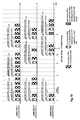
- Fig. 10 shows exemplary power headroom reporting in a LTE-A system, assuming that the power headroom reporting of LTE Rel. 8 is applied to each of the exemplary three component carriers (CoCa1 to CoCa3).
- T 1 there is an uplink assignment on all three component carriers and an uplink transport block, respectively MAC PDU, including a power headroom report for the respective component carrier is sent on each component carrier.
- per-CC per-component carrier
- the eNodeB is informed on the user equipment's power status. Furthermore, the respective timers periodicPHR-Timer and prohibitPHR-Timer are restarted for each component carrier.
- the user equipment transmits a transport block/MAC PDU with a power headroom report only on component carrier CoCa1.
- the eNodeB may again conclude on the user equipment's power status from the per-CC power headroom report at T 2 .
- T 3 , T 4 , and T 5 only some transport blocks/PDUs of the component carriers within a sub-frame carry a power headroom report.
- the power headroom report on component carrier CoCa3 at T 5 a path-loss change on component carrier CoCa3 is assumed to trigger the power headroom report, but at the time of the path-loss change none of the component carriers with uplink transmissions (i.e. component carriers CoCa1 and CoCa2) have a power headroom report included. Therefore, T 3 , T 4 , and T 5 , the eNodeB is not aware of the actual transmit power spend on the uplink transmissions within the respective sub-frames.
- One object of the invention is to propose procedures that allow the eNodeB to recognize the power usage status of a user equipment in a mobile communication system using carrier aggregation.
- One aspect of the invention is to enable to UE to indicate to the eNodeB when it is potentially becoming power limited or is power limited, i.e. when being close to using its maximum available transmit power or the resource allocations and power control commands of the eNodeB would require using a transmit power exceeding the user equipment's maximum available transmit power. This is achieved by defining a new MAC control element that is inserted by the user equipment to one or more protocol data units transmitted on respective (assigned) component carriers within a single sub-frame that is providing the eNodeB with a corresponding indication.
- control element inserted to the protocol data units may further indicate a per-user equipment (per-UE) power headroom.
- per-UE per-user equipment
- the per-user equipment power headroom indicates the transmit power unused by the user equipment when transmitting the protocol data units (including the MAC control element) within the sub-frame relative to the user equipment's maximum available transmit power.
- the MAC control element may be inserted to the protocol data units of a sub-frame.
- the MAC control element may be inserted into one of the protocol data units transmitted by the user equipment within the sub-frame or all of the protocol data units transmitted by the user equipment within the sub-frame.
- the object is solved by the user equipment sending per-component carrier power headroom reports for all assigned component carriers within a single sub-frame when the user equipment is potentially becoming power limited or is power limited, i.e. when being close to using its maximum available transmit power or the resource allocations and power control commands of the eNodeB would require using a transmit power exceeding the user equipment's maximum available transmit power.
- One embodiment of the present invention provides a method for informing an eNodeB on the power status of a user equipment in a mobile communication system using component carrier aggregation.
- the user equipment determines whether an estimated transmit power required for transmitting protocol data units on respective component carriers within a sub-frame will exceed a threshold value relative to a maximum available transmit power of the user equipment. If the threshold value is exceeded, the user equipment multiplexes a MAC control element to the protocol data units and transmits the protocol data units including the MAC control element to the eNodeB within the sub-frame.
- the MAC control element indicates to the eNodeB that the transmit power spent by the user equipment for transmitting the generated protocol data units on uplink exceeded the threshold value, i.e. is reporting the power headroom per-user equipment.
- the threshold value may be for example defined as a percentage of the maximum the user equipment is allowed to use.
- the MAC control element provides the eNodeB with a per-user equipment power headroom relative to all uplink protocol data units transmitted in the sub-frame.
- the per-user equipment power headroom could account for all transmissions on a physical uplink shared channel (PUSCH) and a physical uplink control channel (PUCCH) within the sub-frame.
- PUSCH physical uplink shared channel
- PUCCH physical uplink control channel
- At least one uplink resource assignment is received, wherein each uplink resource assignment is assigning resources for the transmission of one of the protocol data units on one of the plural component carriers to the user equipment.
- For each received uplink resource assignment a protocol data unit is generated for transmission on the respective assigned component carrier.
- Each protocol data unit is transmitted via a corresponding one of the component carriers according to one of the received resource assignments.
- generating for each received uplink resource assignment a protocol data unit comprises said multiplexing of the MAC control element to at least one of said protocol data units.
- the MAC control element is multiplexed to one of the protocol data units or to each of the protocol data units.
- the protocol data units may be for example generated by executing a joint logical channel prioritization procedure.
- the component carriers each have a priority
- the MAC control element is multiplexed to the protocol data unit to be transmitted on the highest priority component carrier for which a resource assignment has been received.
- the component carriers each have a priority
- the MAC control element is multiplexed to the protocol data unit to be transmitted on the component carrier achieving the lowest block error rate, having the largest power headroom or experiencing the best channel quality, and for which a resource assignment has been received.
- the estimated transmit power is estimated based on the resource assignments for the protocol data units to be transmitted in the sub-frame and the status of a transmit power control function.
- radio resource control signaling is received from the eNodeB indicating said threshold value as a percentage of the maximum the user equipment is allowed to use.
- the threshold value is configured according to the indicated percentage.
- Another embodiment of the invention provides another alternative method for informing an eNodeB on the power status of a user equipment in a mobile communication system using component carrier aggregation.
- Protocol data units are transmitted in each of a predetermined number of successive sub-frames (monitoring period) from the user equipment to the eNodeB.
- a MAC control element is multiplexed to the protocol data units of the last sub-frame of said predetermined number of successive sub-frames transmitted by the user equipment, if one of the following conditions is met:
- the MAC control element thus indicates to the eNodeB that the respective condition was met.
- the number of sub-frames of said subset is configured by RRC control signaling received at the user equipment from the eNodeB or is predefined.
- a MAC control element for transmission from a user equipment to a eNodeB in a mobile communication system using component carrier aggregation.
- the MAC control element comprises a power headroom field consisting of a predetermined number of bits for comprising a per-user equipment power headroom with respect to all uplink transmissions of the user equipment on a plurality of component carriers within a sub-frame containing the MAC control element, relative to the maximum available transmit power of the user equipment.
- the MAC control element comprises a component carrier indicator field for indicating
- the power headroom field comprises either said per-user equipment power headroom or a per-component carrier power headroom.
- the MAC control element comprises a component carrier indicator field that is indicating whether the power headroom field comprises said per-user equipment power headroom or said per-component carrier power headroom.
- An additional embodiment of the invention provides a MAC protocol data unit for transmission from a user equipment to a eNodeB in a mobile communication system using component carrier aggregation.
- the MAC protocol data unit comprises a MAC subheader and a MAC control element according to one of the embodiments thereof described herein.
- the MAC subheader comprises a logical channel identifier (LCID) that is indicating the content and format of said MAC control element.
- LCID logical channel identifier
- a user equipment for informing a eNodeB on the power status of a user equipment in a mobile communication system using component carrier aggregation.
- An determining section of the user equipment determines whether an estimated transmit power required for transmitting protocol data units on respective component carriers within a sub-frame will exceed a threshold value relative to a maximum available transmit power of the user equipment.
- a protocol data unit generation section of the user equipment multiplexes a MAC control element to the protocol data units, if the threshold value is exceeded.
- a transmitting section of the user equipment transmits the protocol data units including the MAC control element to the eNodeB within the sub-frame.
- the MAC control element indicates to the eNodeB that the transmit power spent by the user equipment for transmitting the generated protocol data units on uplink exceeded the threshold value.
- the MAC control element provides the eNodeB with a per-user equipment power headroom relative to all uplink protocol data units transmitted in the sub-frame.
- a receiving section of the user equipment receives at least one uplink resource assignment.
- Each uplink resource assignment is assigning resources for the transmission of one of the protocol data units on one of the plural component carriers to the user equipment.
- a protocol data unit generation section of the user equipment generates for each received uplink resource assignment a protocol data unit for transmission on the respective assigned component carrier.
- the transmitting section transmits each protocol data unit via a corresponding one of the component carriers according to one of the received resource assignments.
- the component carriers each have a priority
- a protocol data unit generation section of the user equipment multiplexes the MAC control element to the protocol data unit to be transmitted on the highest priority component carrier for which a resource assignment has been received.
- the component carriers each have a priority
- a protocol data unit generation section of the user equipment multiplexes the MAC control element to the protocol data unit to be transmitted on the component carrier achieving the lowest block error rate, having the largest power headroom or experiencing the best channel quality, and for which a resource assignment has been received.
- a power control section of the user equipment performs power control, and the determining section determines the estimated transmit power based on the resource assignment for the protocol data units to be transmitted in the sub-frame and the status of a transmission power control section.
- a receiving section of the user equipment receives radio resource control signaling from the eNodeB indicating said threshold value as a percentage of the maximum the user equipment is allowed to use.
- a configuration section of the user equipment configures the threshold value according to the indicated percentage.
- a further embodiment of the invention provides a computer readable medium storing instructions that, when executed by a processor of a user equipment, cause the user equipment to inform am eNodeB on the power status of a user equipment in a mobile communication system using component carrier aggregation. This is done as follows. It is determined whether an estimated transmit power required for transmitting protocol data units on respective component carriers within a sub-frame will exceed a threshold value relative to a maximum available transmit power of the user equipment. If the threshold value is exceeded, a MAC control element is multiplexed to the protocol data units. The protocol data units including the MAC control element are transmitted to the eNodeB within the sub-frame. The MAC control element indicates to the eNodeB that the transmit power spent by the user equipment for transmitting the generated protocol data units on uplink exceeded the threshold value.
- One aspect of the invention is to enable to UE to indicate to the eNodeB when it is potentially becoming power limited or is power limited, i.e. when being close to using its maximum available transmit power or the resource allocations and power control commands of the eNodeB would require using a transmit power exceeding the user equipment's maximum available transmit power. This is achieved by defining a new MAC control element that is inserted by the user equipment to one or more protocol data units transmitted on respective (assigned) component carriers within a single sub-frame that is providing the eNodeB with a corresponding indication.
- the transmission of protocol data units in a sub-frame means that there has been a resource allocation for a respective one of the protocol data units on a respective one of the component carriers usable by the user equipment.
- Usable means that the user equipment can be assigned resources on each of these component carriers ⁇ however, the component carriers on which the user equipment is allowed to transmit data (in form of protocol data units) within a given sub-frame is decided by the scheduler (e.g. implemented in the eNodeB) and is controlled by the resource assignments to the user equipment.
- a transmission on an "assigned component carrier” refers to a transmission of a protocol data unit on a component carrier for which the user equipment has received a resource assignment (also referred to as scheduling grant, grant (for short) or PDCCH).
- the MAC control element may be inserted to the protocol data units of a sub-frame.
- the MAC control element may inserted into one of the protocol data units transmitted by the user equipment within the sub-frame or all of the protocol data units transmitted by the user equipment within the sub-frame.
- the control element inserted to the protocol data units may further indicate a per-user equipment (per-UE) power headroom.
- the per-user equipment power headroom indicates the transmit power unused by the user equipment when transmitting the protocol data units (including the MAC control element) within the sub-frame relative to the user equipment's maximum available transmit power.
- the power headroom indicated in the MAC control element is considering the transmissions (protocol data units) on all assigned component carriers (i.e. more than one component carrier) within the sub-frame and is therefore not per-component carrier, but per-user equipment.
- this per-user equipment power headroom is not only taking into account the transmit power required for the transmission of protocol data units via physical uplink data channels, but also the transmit power required for the transmission of control signaling via physical control channels. In one more detailed implementation is thus accounting for the transmit power required for transmitting user data and control data (protocol data units) on the assigned component carriers via the physical uplink shared channel (PUSCH) and the physical uplink control channel (PUCCH).
- PUSCH physical uplink shared channel
- PUCCH physical uplink control channel
- the object is solved by the user equipment sending per-component carrier power headroom reports for all assigned component carriers within a single sub-frame when the user equipment is potentially becoming power limited or is power limited, i.e. when being close to using its maximum available transmit power or the resource allocations and power control commands of the eNodeB would require using a transmit power exceeding the user equipment's maximum available transmit power.
- the per-component carrier power headroom reports for all assigned component carriers are transmitted on the respective assigned component carriers to which they refer.
- a potentially employed prohibit timer controlling the power headroom reporting on a respective one of the assigned component carrier is overwriften/ignored.
- the per-component carrier power headroom reports are transmitted within a single protocol data unit on one of the assigned component carriers.
- the respective component carrier to which a respective per-component carrier power headroom report refers may be for example identified by including a component carrier identifier into the power headroom reports.
- the decision of whether the user equipment is approaching (or is in) a power limit situation may be determined in different fashions.
- the user equipment determines (or more correctly estimates) the transmit power it will have to spend for transmitting the protocol data units on the assigned component carriers within a sub-frame and compares the determined (or estimated) transmit power to a threshold.
- This threshold may be for example a certain percentage (e.g. in the range 80% to 100%) of the maximum available transmit power.
- the user equipment determines (or more correctly estimates) the transmit power it will have to spend for transmitting the protocol data units on the assigned component carriers within a sub-frame for a given number of successive sub-frames (i.e. a monitoring time period) and decides based on criteria further outlined below, whether to include a MAC control element to indicate a power limit situation to the protocol data units of the last sub-frame of said monitoring time period.
- the user equipment is operated in a mobile communication system that is using carrier aggregation and that the user equipment is configured with plural component carriers, i.e. is capable of transmitting uplink data on plural component carriers simultaneously within individually sub-frames according to resource assignments of a scheduler.
- the scheduler is for example implemented in the eNode B.
- the scheduler may assign one or more (up to all) of the plurality of configured component carriers for a given sub-frame and the user equipment is transmitting a respective transport block/protocol data unit on each assigned component carrier, i.e. each component carrier for which a resource assignment has been received.
- the resource assignments may also be referred to as grants or PDCCH.
- the there may be a respective transmit power loop implemented per component carrier configured for the user equipment, i.e. the transmit power control function implemented in the user equipment and the eNodeB perform transmit power control for each component carrier individually.
- a joint logical channel prioritization procedure may be used for to the generation of the protocol data units for transmission within a sub-frame.
- Different exemplary implementations of such joint logical channel prioritization procedure are described in the co-pending European patent application no. 09005727.4 of the same applicant (attorney's docket no. EP64934DKFH) and the co-pending European patent application with the title "Logical Channel Prioritization Procedure for generating Multiple Uplink Transport Blocks" of the same applicant filed October 29, 2009 (attorney's docket no. EP649341DKFH).
- the two European patent applications will be referred to as Application 1 and Application 2 in the following where appropriate.
- Fig. 8 shows a flow chart of an exemplary operation of a user equipment according to one embodiment of the invention in line with the first aspect of the invention.
- the user equipment receives 801 plural resource assignments for a given sub-frame and estimates 802 the transmit power (ETP) required for uplink transmissions on assigned component carriers according to received resource assignments.
- the transmit power is estimated by the user equipment based on the received resource assignments for the protocol data units to be transmitted in the sub-frame and the status of a transmit power control function of the user equipment.
- the user equipment may estimate the transmit power needed for each of the resource blocks depending on which component carrier they are located on and based on the state of the transmit power function of the component carrier.
- the estimated transmit power is then the sum of the individual transmit power for all assigned resource blocks.
- the user equipment determines 803, whether the estimated transmit power (ETP) is exceeding a certain threshold value.
- this threshold is defined as a certain percentage P of the maximum available transmit power (MATP) of the user equipment.
- this would be equivalent to determining whether the ratio of the estimated transmit power (ETP) and the maximum available transmit power (MATP), is exceeding a threshold value, that would be equivalent to the percentage P, i.e. ETP MATP > P .
- the user equipment will next generate 804 the protocol data units for transmission on the respective assigned component carriers and transmits 805 the protocol data units (which are referred to as transport blocks in the Physical layer) to the eNodeB via the assigned component carriers.
- the generation of the protocol data units can be for example implemented as described in Application 1 or Application 2.
- the user equipment determines 806 the per-user equipment power headroom for all transmissions according to the resource assignments. As outlined above, this per-user power headroom is determined for all protocol data units to be transmitted within the given sub-frame on the assigned component carriers.
- the user equipment further generates 807 a MAC control element that is comprising the determined per-user equipment power headroom ("per-UE power headroom MAC CE") and provides the per-UE power headroom MAC CE to a protocol data generation section that generates 808 the protocol data units for transmission according to the resource assignments, similar to step 804.
- the per-UE power headroom MAC CE is included in this generation process, so that depending on the implementation per-UE power headroom MAC CE is included in one of the protocol data units or all of the protocol data units.
- the generated protocol data units including the per-UE power headroom MAC CE are transmitted 809 to the eNodeB on the assigned resources.
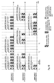
- Fig. 11 shows power headroom reporting in a LTE-A system according to an embodiment of the invention, where the exemplary operation of a user equipment according to Fig. 8 is employed. In most situations, the operation is corresponding to the operation of the user equipment as has been outlined with respect to Fig. 10 previously herein. In contrast to Fig. 10 , it is assumed that at T 6 the user equipment has received three resources assignments for all three component carriers for the sub-frame at T 6 , however the transmit power control function has is yielding a gain factor for the transmission that high that given the resource allocation, the estimated transmit power exceeds the maximum available transmit power (see step 803 of Fig. 8 ).
- the user equipment determines the per-UE power headroom and multiplexes the per-UE power headroom MAC CE (also referred to as power-limit MAC CE in the following) to the protocol data unit transmitted on component carrier CoCa1.
- the scheduler in the eNodeB receiving the uplink transmission can now detect based on the per-UE power headroom MAC CE that the user equipment is in a power limit situation and can adapt the further scheduling and/or power control of the user equipment accordingly.
- per-UE power headroom MAC CE may basically have two functions. The first and most important function is that the sole reception of the per-UE power headroom MAC CE by eNodeB already informs eNodeB that a problem with the transmit power for the uplink transmissions existed in the sub-frame. Secondly, the per-UE power headroom MAC CE may also be reporting the per-user equipment power headroom of the user equipment, thus yielding more detailed information on the exact power situation in the user equipment to the eNodeB.
- the user equipment is not immediately including a power-limit MAC CE to the protocol data units transmitted on the uplink if the estimated transmit power exceeds the threshold. For example when the threshold is exceeded, instead of transmitting the power-limit MAC CE immediately, the user equipment start monitoring the estimated transmit power for a certain number of sub-frames, i.e. for a given monitoring period of sub-frames. Having monitored the given number of sub-frames, the user equipment decides whether or not a power-limit MAC CE is to be included to the protocol data units to be transmitted in the next sub-frame following certain criteria. Please note that the power-limit MAC CE may for example be transmitted in the last sub-frame transmitted in the monitoring period, if the user equipment decides to insert same.
- the monitoring of the estimated transmit power for a given time period i.e. a certain number for sub-frames, has the advantage that the power-limit MAC CE is not reported immediately when the threshold is crossed, which may avoid unnecessary reporting of a power-limit situation to the eNodeB if the threshold is exceeded only sporadically.
- the drawback of introducing a monitoring period is the delay in the transmission of the power-limit MAC CE, once user equipment's transmit power has crossed the threshold.
- the user equipment is configured with two thresholds.
- the second, "additional" threshold may be for example set by the eNodeB by RRC signaling.
- This second threshold may for example also be a fraction of the maximum available transmit power of the user equipment, but is preferably higher than the first threshold.
- the user equipment again determines for each sub-frame whether the estimated transmit power of a sub-frame exceeds the first threshold. If this is the case, i.e. the first threshold is exceeded for a sub-frame, the user equipment starts monitoring the estimated transmit power as described in the paragraphs above, for example for a given monitoring period. If the second threshold is exceeded by the estimated transmit power of a sub-frame within the monitoring period, the user equipment transmits a power-limit MAC CE within that sub-frame for which the estimated transmit power exceeded the second threshold was crossed.
- the user equipment is multiplexing the power-limit MAC CE to each of the protocol data units sent in the sub-frame via the assigned component carriers. This may be advantageous in that the reliability of the reception of the control element by eNodeB is increased.
- the format for the per-UE power headroom MAC CE indicating a potential power limitation of the user equipment could be based on the LTE Rel. 8 MAC CE format used for power headroom reporting as exemplified in Fig. 7 .
- the power headroom MAC CE consists of 8 bits, i.e. one octet, The first two bits are reserved bits, and the remaining 6 bits indicate the power headroom.
- the format is maintained, but the 6 bit-field PH of the MAC CE format shown in Fig. 7 includes the a per-UE power headroom determined by the user equipment (see for example step 806 of Fig. 8 ).
- the per-UE power headroom does not only transmissions on the PUSCH but also transmissions on the PUCCH is taken into account while calculating the per-UE power headroom.
- one of the two reserved bits (R) of the octet shown in Fig. 8 e.g. the highest bit in the octet, is used to differentiate power headroom MAC CEs and power-limit MAC CEs (i.e. the per-UE power headroom CEs). For example, if the highest bit in the octet is set to 0, the MAC CE represents a power headroom report for that component carrier, i.e.
- a per-component carrier MAC CE reporting a power headroom for the given component carrier - the per-component carrier MAC CE reporting on the power headroom is thus a component carrier-specific MAC control element. If the bit is set to 1, the reported power headroom is the per-UE power headroom of the power-limit MAC CE.
- the power-limit MAC CE i.e. the per-UE power headroom CE can be considered to be UE specific, so that the power-limit MAC CE can be considered a UE-specific MAC control element.
- UE-specific and component carrier-specific MAC control elements may lead to a different treatment and multiplexing of the MAC control element to the transport block (MAC protocol data units) as explained in Application 2.
- the eNodeB When user equipment is sending a power-limit MAC CE, it may be of additional value to the eNodeB to acquire knowledge for which component carriers the user equipment actually received resource assignments (uplink grants) in order to know, if the user equipment obeyed all uplink grants correctly, or if it missed one or more of the uplink grants. This information allows the eNodeB to determine, if the power-limit situation exists already for a situation where the user equipment did not even transmit on all the granted resources due having missed one or more of the uplink grants.
- the another exemplary format for the power-limit MAC CE is proposed which is including information on the component carriers for which uplink grants have been received, respectively on the number of received uplink grants.
- FIG. 14 An exemplary format of the power-limit MAC CE according to another embodiment of the invention is shown in Fig. 14 .
- This power-limit MAC CE consists of two fields, a first field CCI (Component Carrier Indicator field) and a second field PH (Power Headroom) for indicating the per-UE power headroom.
- the power-limit MAC CE is again one octet long.
- the component carriers other than the one on which the MAC CE is signaled, for which an uplink grant has been received may be for example indicated by means of a bitmap.
- the actual mapping of which bit in the bitmap represents which component carrier could be for example configured by eNodeB through RRC signaling or can be determined by a priority order of the component carriers, as for example outlined in Application 1 and Application 2.
- MAC CE format shown in Fig. 15 is suggested.
- the CCI field is only 3 bits in size, while the PH field has 5 bits.
- This format may be considered a modification of the LTE Rel. 8 power headroom report MAC CE format in Fig. 7 in that the two reserved bits (R) and one additional bit from the PH field are reused as the CCI field. This implies of course reducing the granularity of the per-UE power headroom values that can be reported from 6 to 5 bits.
- the MAC CE format for reporting a per-UE power headroom as shown in Fig. 15 allows for indicating the number of component carriers for which the user equipment received an uplink assignment while also indicating the whether the MAC control element is a LTE Rel. 8 power headroom MAC CE or a per-UE power headroom MAC CE, without requiring the assignment of a new logical channel identifier (LCID) to the new per-UE power headroom MAC CE but being able to also use the same LCID for a LTE Rel. 8 power headroom MAC CE and per-UE power headroom MAC CE .
- LCID logical channel identifier
- the eNodeB would have to evaluate the first two bits of the control element to determine whether a LTE Rel. 8 power headroom MAC CE or a per-UE power headroom MAC CE.
- Table 1 CCi Field 1 st R bit 2 nd R bit 1 st bit of PH field Meaning 0 0 Highest bit of 6bit-PH field LTE Rel.
- the MAC control element is a LTE Rel. 8 power headroom report as shown in Fig. 7 .
- the MAC control element is a per-UE power headroom MAC CE. If the first two bits are not set to 0, the eNodeB needs to also evaluate the third bit within the octet, as the first three bits yield the number of uplink grants received by the user equipment. The remaining five bits (see Fig. 15 ) - the PH field - indicate the per-UE power headroom value.
- the power-limit MAC CE may be used to not only signal the per-UE power headroom in a PH field, but to also suggest to the eNodeB for which component carriers the eNodeB should further send resource assignments. In one example, this is implemented in a similar fashion as described previously herein with respect to Fig. 14 .
- the four bits of the CCI field may be used to signal a bitmap that indicates on which the component carriers (other than the one on which the power-limit MAC CE is received), the eNodeB should continue to give grants on.
- the bitmap could represent the component carriers the eNodeB should stop giving grants on.
- the MAC CE as shown in Fig. 7 is used for the per-UE power headroom reporting.
- One of the two reserved bits, e.g. the first reserved bit shown in Fig. 7 is used to identify whether the MAC CE is a LTE Rel. 8 power headroom MAC CE or a per-UE power headroom MAC CE.
- the PH field may be 6 bits and indicates a per-component carrier headroom as in LTE Rel. 8 or the per-UE power headroom.
- the MAC control element is a per-UE power headroom MAC CE, the component carrier on which the control element has been transmitted is the component carrier the user equipment is suggesting to the eNodeB for further resource assignments thereon.
- a MAC PDU yields the format of the MAC control elements included in the MAC PDU payload by respective logical channel identifiers in the subheader of the respective MAC control elements.
- a new logical channel identifier is defined for indicating a per-UE power headroom MAC CE.
- this embodiment of the invention provides a MAC PDU comprising a subheader ("per-UE power headroom MAC CE subheader") and the related MAC CE.
- the per-UE power headroom MAC CE subheader comprises a LCID that is identifying the related MAC CE being a per-UE power headroom MAC CE.
- the format of the per-UE power headroom MAC CE may be again that described in one of the embodiments relating to Fig. 7 , Fig. 14 or Fig. 15 above, however, no indicating of a LTE Rel. 8 power headroom MAC CE may need to be included in the format definition any more, as the differentiation of the LTE Rel. 8 power headroom MAC CE and per-UE power headroom MAC CE is now achieved by means of the LCID in the subheader of the MAC PDU.
- the user equipment may calculate the transmit power needed to fulfill all uplink grants (resource assignments) in that sub-frame, i.e. determines the estimated transmit power required in this sub-frame.
- a threshold is configured relative to the maximum available transmit power which essentially indicates the maximum transmit power the user equipment is allowed to (or able to) spend on all uplink transmissions on the assigned component carriers in the specific sub-frame.
- the threshold may be, for example, configured by the eNodeB in relation to the maximum available transmit power.
- the threshold may be, for example, set by eNodeB for each user equipment individually and the value of the threshold could be, for example, conveyed to respective user equipments via RRC signaling.
- the threshold may be for example a fractional value of (or percentage P) of the maximum available transmit power.
- the power-limit MAC CE is included in the uplink transmissions of the sub-frame.
- the user equipment's estimated transmit power might not only cross the configured threshold but may be even above the maximum available power available to the user equipment. In the latter case user equipment is already in a severe power-limited situation and cannot fulfill all uplink resource assignments as demanded by eNodeB.
- the transmit power that is available for UL transmissions is already critical. Therefore the transport block of the most reliable component carrier needs to be chosen for the inclusion of the power-limit MAC control element.
- the criterion for the selection of the most reliable component carrier can be based on the following conditions.
- One option would be to choose the component carrier which is the "special cell", i.e. the component carrier where the UE camps on and reads system information from.
- Another option would be to choose from the set of component carriers with UL transmissions the one with the best physical parameters. Parameters could be for example the target BLER or the actual power headroom of a component carrier.
- a priority ranking of the component carriers is already known to UE the UE could send the power-limit MAC CE always on the component carrier with the highest priority.
- the user equipment sends a per-component carrier (per-CC) power headroom report for each assigned component carrier of the sub-frame to inform the eNode B on a situation where the user equipment is close to using its maximum available transmit power or the resource allocations and power control commands of the eNodeB would require using a transmit power exceeding the user equipment's maximum available transmit power.
- per-CC per-component carrier
- the user equipment could re-use the power headroom reporting mechanism (including the user of the timers periodicPHR-Timer and prohibitPHR-Timer) and their format as shown in Fig. 7 know from LTE Rel. 8 for each respective report sent in the sub-frame.
- the user equipment When the user equipment is in a situation where it is close to using its maximum available transmit power or the resource allocations and power control commands of the eNodeB would require using a transmit power exceeding the user equipment's maximum available transmit power, the user equipment will send on each assigned component carrier a per-CC power headroom report as known from LTE Rel. 8 for the respective component carrier. In doing so the user equipment ignores the timer prohibitPHR-Timer, if running. Subsequent to the transmission of the multiple per-CC power headroom reports, the timers periodicPHR-Timer and prohibitPHR-Timer may be restarted.
- the eNodeB Upon reception of all power headroom reports in the sub-frame, the eNodeB has the full picture of the total power situation of the user equipment.
- the per-CC power headroom reports on all assigned component carriers could be send in only one MAC PDU on one of the assigned component carriers.
- the selection of this component carrier on which the power headroom reports are to be sent can be implemented as described previously herein (see inter alia section Selection of the Component Carrier for transmitting the per-UE power headroom MAC CE).
- the multiple per-CC power headroom reports could be included into one MAC PDU.
- An exemplary format of a MAC PDU containing multiple PHR MAC CEs is shown in Fig. 17 , where a report of three power headroom reports on assigned component carriers CoCa1, CoCa3 and CoCa4 is exemplified.
- the MAC PDU comprises first the component carrier-specific logical channel identifiers (LCID S ) within respective subheaders field that allow the identification of the component carriers reported on and indicate that the MAC PDU's payload section comprises three PHR MAC CEs.
- Each subheader (indicating the LCID) is 8 bits long (one octet), wherein the first two bits of the octet (R) are reserved bits, and the third bit (E) indicates whether the next octet in the MAC PDU is another subheader of the MAC PDU header or whether the payload section of the MAC PDU is following the octet (i.e. whether the next octet is PHR MAC CE in this example), and the last 5 bits are the LCID.
- next octet is part of the payload section of the MAC PDU that is assumed to start with the first PHR MAC CE.
- the power headroom reports on multiple component carriers may also be included into a single MAC control element ("multiple PHR MAC CE").
- the multiple PHR MAC CE comprises in its first octet a bitmap of 5 bits indicating for which component carrier a PHR field is included in the multiple PHR MAC CE.
- a priority order of the component carriers may define the meaning of the individual positions of bits within the bitmap.
- a bit set e.g. 1 at a certain position of the bitmap means that there is a PHR field for the associated component carrier including in the MAC CE.
- the respective PHR field(s) with the power headroom value for the component carrier is/are included.
- the PHR field may for example have the same format as shown in Fig. 7 and reports the power headroom (PH) for a component carrier.
- An example of a multiple PHR MAC CE where a report of three power headroom reports on assigned component carriers CoCa1, CoCa3 and CoCa4 is exemplified in Fig. 18 .
- LTE Rel. 8 power headroom reports and the multiple PHR MAC CE could use the same logical channel identifier, and the two formats may be distinguished by setting or not setting the first or second reserved bit in the first octet of the control element.
- the multiple PHR MAC CE may also be assigned its own logical channel identifier (LCID) in the MAC PDU header.
- LCID logical channel identifier
- the multiple PHR MAC CE may be further assigned its own logical channel identifier, so that it can be identified by a corresponding subheaders in the MAC PDU's header (see Fig. 6 ).
- Fig. 9 shows a flow chart of an exemplary operation of a user equipment according to one embodiment of the invention in line with the second aspect of the invention. Similar to Fig. 8 , the user equipment receives 801 plural resource assignments for a given sub-frame and estimates 802 the transmit power (ETP) required for uplink transmissions on assigned component carriers according to received resource assignments. Next, the user equipment determines 803, whether the estimated transmit power (ETP) is exceeding a certain threshold value. If the threshold value is not exceeded, the user equipment is not in a power limit situation, so that report thereon needs to be signaled to the eNodeB.
- ETP transmit power
- the user equipment will next generate 804 the protocol data units for transmission on the respective assigned component carriers and transmits 805 the protocol data units (which are referred to as transport blocks in the Physical layer) to the eNodeB via the assigned component carriers.
- the generation of the protocol data units can be for example implemented as described in Application 1 or Application 2.
- the user equipment determines 906 for each component carrier for which a resource assignment has been received a per-CC power headroom.
- This per-CC power headroom may be for example determined as described in 3GPP TS 36.213, "Physical layer procedures", version 8.8.0, section 5.1.1, the document being available at http://www.3gpp.org and being incorporated herein by reference.
- the user equipment may generate 907 for each assigned component carrier an individual per-CC power headroom MAC CE (for example using the format shown in Fig. 7 ) and further generates 908 the MAC PDUs including each the corresponding per-CC power headroom MAC CE according to the resource assignments. Subsequently the user equipment transmits the PDUs including per-CC power headroom MAC CEs on the assigned component carriers to the eNode B.
- an individual per-CC power headroom MAC CE for example using the format shown in Fig. 7
- the user equipment transmits the PDUs including per-CC power headroom MAC CEs on the assigned component carriers to the eNode B.
- steps 907 and 908 there could also be a single multiple PHR MAC CE formed and transmitted in one of the MAC PDUs, as outlined above.
- Fig. 12 shows power headroom reporting in a LTE-A system according to an embodiment of the invention, where the exemplary operation of a user equipment according to Fig. 9 is employed. In most situations, the operation is corresponding to the operation of the user equipment as has been outlined with respect to Fig. 10 previously herein. In contrast to Fig. 10 , it is assumed that at T 6 the user equipment has received three resources assignments for all three component carriers for the sub-frame at T 6 , however the transmit power control function has is yielding a gain factor for the transmission that high that given the resource allocation, the estimated transmit power exceeds the maximum available transmit power (see step 803 of Fig. 9 ).
- the user equipment determines the per-CC power headroom values for all three component carriers and sends PDUs each comprising a per-CC power headroom report for the respective component carrier in the uplink.
- the prohibitPHR-Timer is running at T 6 for the component carrier CoCa3, but is ignored by the user equipment.
- the respective timers are restarted for each component carrier.
- Fig. 13 shows another exemplary power headroom reporting in a LTE-A system according to an embodiment of the invention, where the exemplary operation of a user equipment according to Fig. 9 is employed.
- the example shown therein is the same as in Fig. 12 , except for the user equipment having been assigned only resources on component carriers CoCa1 and CoCa3 for the sub-frame at T 6 .
- the user equipment Similar to Fig. 12 , the user equipment still is in a power limit situation for this sub-frame, but sends a single multiple PHR MAC CE in the PDU transmitted on component carrier CoCa1 that reports the power headrooms for component carriers CoCa1 and CoCa3.
- the timers periodicPHR-Timer and prohibitPHR-Timer are restarted for the component carriers for which a per-CC power headroom report has been sent, i.e. component carriers CoCa1 and CoCa3 in this example.
- a computing device or processor may for example be general purpose processors, digital signal processors (DSP), application specific integrated circuits (ASIC), field programmable gate arrays (FPGA) or other programmable logic devices, etc.
- DSP digital signal processors
- ASIC application specific integrated circuits
- FPGA field programmable gate arrays
- the various embodiments of the invention may also be performed or embodied by a combination of these devices.
- the various embodiments of the invention may also be implemented by means of software modules, which are executed by a processor or directly in hardware. Also a combination of software modules and a hardware implementation may be possible.
- the software modules may be stored on any kind of computer readable storage media, for example RAM, EPROM, EEPROM, flash memory, registers, hard disks, CD-ROM, DVD, etc.
Priority Applications (38)
| Application Number | Priority Date | Filing Date | Title |
|---|---|---|---|
| EP09013756A EP2317815A1 (en) | 2009-11-02 | 2009-11-02 | Power-limit reporting in a communication system using carrier aggregation |
| EP10008477A EP2317816A1 (en) | 2009-11-02 | 2010-08-13 | Power-limit reporting in a communication system using carrier aggregation |
| HUE10773252A HUE039501T2 (hu) | 2009-11-02 | 2010-10-20 | Teljesítményhatár-jelentés kommunikációs rendszerben vivõösszerakáshoz |
| RS20181087A RS57812B1 (sr) | 2009-11-02 | 2010-10-20 | Izveštavanje o limitiranju snage u komunikacionom sistemu koji koristi agregaciju nosilaca |
| PT10773252T PT2497318T (pt) | 2009-11-02 | 2010-10-20 | Comunicação de limite de potência num sistema de comunicações utilizando agregação de portadoras |
| PCT/EP2010/006423 WO2011050921A1 (en) | 2009-11-02 | 2010-10-20 | Power-limit reporting in a communication system using carrier aggregation |
| US13/503,739 US8811322B2 (en) | 2009-11-02 | 2010-10-20 | Power limit reporting in a communication system using carrier aggregation |
| SI201031761T SI2497318T1 (sl) | 2009-11-02 | 2010-10-20 | Poročanje o omejitvi moči v komunikacijskem sistemu z uporabo združevanja nosilcev |
| BR112012010022-0A BR112012010022B1 (pt) | 2009-11-02 | 2010-10-20 | método para informar a um enodeb o estado de potência de transmissão de um equipamento de usuário em um sistema de comunicação móvel utilizando agregação de portadora componente e equipamento de usuário para informar a um enodeb o estado de potência de transmissão de um equipamento de usuário em um sistema de comunicação móvel utilizando agregação de portadora componente |
| EP19194607.8A EP3592080B1 (en) | 2009-11-02 | 2010-10-20 | Power-limit reporting in a communication system using carrier aggregation |
| AU2010311871A AU2010311871B2 (en) | 2009-11-02 | 2010-10-20 | Power-limit reporting in a communication system using carrier aggregation |
| EP18172137.4A EP3383114B1 (en) | 2009-11-02 | 2010-10-20 | Power-limit reporting in a communication system using carrier aggregation |
| CN201080060276.9A CN102687577B (zh) | 2009-11-02 | 2010-10-20 | 使用载波聚合的通信系统中的功率限制报告 |
| LTEP10773252.1T LT2497318T (lt) | 2009-11-02 | 2010-10-20 | Ataskaitos apie ribinę galią ryšio sistemoje, naudojančioje nešlio agregavimą, pateikimas |
| PL10773252T PL2497318T3 (pl) | 2009-11-02 | 2010-10-20 | Raportowanie limitu mocy w systemie łączności mobilnej wykorzystującym agregację nośnych |
| DK10773252.1T DK2497318T3 (en) | 2009-11-02 | 2010-10-20 | EFFICIENCY MESSAGE IN A COMMUNICATION SYSTEM USING SUSTAINABILITY GOVERNMENT |
| JP2012535658A JP5702793B2 (ja) | 2009-11-02 | 2010-10-20 | キャリアアグリゲーションを使用する通信システムにおける電力制限の報告 |
| EP22195021.5A EP4124125A1 (en) | 2009-11-02 | 2010-10-20 | Power-limit reporting in a communication system using carrier aggregation |
| KR1020127011258A KR101706805B1 (ko) | 2009-11-02 | 2010-10-20 | 캐리어 어그리게이션을 이용하는 통신 시스템에서의 파워 제한 보고 |
| ES10773252.1T ES2688231T3 (es) | 2009-11-02 | 2010-10-20 | Notificación de límite de potencia en un sistema de comunicación usando agregación de portadoras |
| EP10773252.1A EP2497318B1 (en) | 2009-11-02 | 2010-10-20 | Power-limit reporting in a communication system using carrier aggregation |
| RU2012117776/07A RU2518083C2 (ru) | 2009-11-02 | 2010-10-20 | Предоставление отчета о предельной мощности в системе связи, использующей агрегацию несущих |
| RU2014112317/07A RU2562612C1 (ru) | 2009-11-02 | 2014-03-31 | Предоставление отчета о предельной мощности в системе связи, использующей агрегацию несущих |
| US14/316,465 US9179424B2 (en) | 2009-11-02 | 2014-06-26 | Power-limit reporting in a communication system using carrier aggregation |
| JP2015032211A JP5902839B2 (ja) | 2009-11-02 | 2015-02-20 | キャリアアグリゲーションを使用する通信システムにおける電力制限の報告 |
| US14/866,696 US9532320B2 (en) | 2009-11-02 | 2015-09-25 | Power-limit reporting in a communication system using carrier aggregation |
| JP2016047153A JP6145902B2 (ja) | 2009-11-02 | 2016-03-10 | キャリアアグリゲーションを使用する通信システムにおける電力制限の報告 |
| US15/353,323 US9794894B2 (en) | 2009-11-02 | 2016-11-16 | Power limit reporting in a communication system using carrier aggregation |
| JP2017088346A JP6350840B2 (ja) | 2009-11-02 | 2017-04-27 | キャリアアグリゲーションを使用する通信システムにおける電力制限の報告 |
| US15/702,607 US10271292B2 (en) | 2009-11-02 | 2017-09-12 | Power-limit reporting in a communication system using carrier aggregation |
| JP2018097827A JP6478135B2 (ja) | 2009-11-02 | 2018-05-22 | キャリアアグリゲーションを使用する通信システムにおける電力制限の報告 |
| CY20181100956T CY1120914T1 (el) | 2009-11-02 | 2018-09-17 | Αναφορα οριου ισχυος σε ενα συστημα επικοινωνιας με χρηση συναθροισης φερουσων |
| HRP20181486TT HRP20181486T1 (hr) | 2009-11-02 | 2018-09-19 | Izvješćivanje ograničenja snage u komunikacijskom sustavu koristeći agregaciju prijenosnika |
| JP2019009518A JP6628067B2 (ja) | 2009-11-02 | 2019-01-23 | キャリアアグリゲーションを使用する通信システムにおける電力制限の報告 |
| US16/291,387 US10764843B2 (en) | 2009-11-02 | 2019-03-04 | Power-limit reporting in a communication system using carrier aggregation |
| US16/938,374 US11350374B2 (en) | 2009-11-02 | 2020-07-24 | Power-limit reporting in a communication system using carrier aggregation |
| US17/728,879 US11895599B2 (en) | 2009-11-02 | 2022-04-25 | Power-limit reporting in a communication system using carrier aggregation |
| US18/543,615 US20240129863A1 (en) | 2009-11-02 | 2023-12-18 | Power-limit reporting in a communication system using carrier aggregation |
Applications Claiming Priority (1)
| Application Number | Priority Date | Filing Date | Title |
|---|---|---|---|
| EP09013756A EP2317815A1 (en) | 2009-11-02 | 2009-11-02 | Power-limit reporting in a communication system using carrier aggregation |
Publications (1)
| Publication Number | Publication Date |
|---|---|
| EP2317815A1 true EP2317815A1 (en) | 2011-05-04 |
Family
ID=42028177
Family Applications (6)
| Application Number | Title | Priority Date | Filing Date |
|---|---|---|---|
| EP09013756A Withdrawn EP2317815A1 (en) | 2009-11-02 | 2009-11-02 | Power-limit reporting in a communication system using carrier aggregation |
| EP10008477A Withdrawn EP2317816A1 (en) | 2009-11-02 | 2010-08-13 | Power-limit reporting in a communication system using carrier aggregation |
| EP19194607.8A Active EP3592080B1 (en) | 2009-11-02 | 2010-10-20 | Power-limit reporting in a communication system using carrier aggregation |
| EP18172137.4A Active EP3383114B1 (en) | 2009-11-02 | 2010-10-20 | Power-limit reporting in a communication system using carrier aggregation |
| EP22195021.5A Pending EP4124125A1 (en) | 2009-11-02 | 2010-10-20 | Power-limit reporting in a communication system using carrier aggregation |
| EP10773252.1A Active EP2497318B1 (en) | 2009-11-02 | 2010-10-20 | Power-limit reporting in a communication system using carrier aggregation |
Family Applications After (5)
| Application Number | Title | Priority Date | Filing Date |
|---|---|---|---|
| EP10008477A Withdrawn EP2317816A1 (en) | 2009-11-02 | 2010-08-13 | Power-limit reporting in a communication system using carrier aggregation |
| EP19194607.8A Active EP3592080B1 (en) | 2009-11-02 | 2010-10-20 | Power-limit reporting in a communication system using carrier aggregation |
| EP18172137.4A Active EP3383114B1 (en) | 2009-11-02 | 2010-10-20 | Power-limit reporting in a communication system using carrier aggregation |
| EP22195021.5A Pending EP4124125A1 (en) | 2009-11-02 | 2010-10-20 | Power-limit reporting in a communication system using carrier aggregation |
| EP10773252.1A Active EP2497318B1 (en) | 2009-11-02 | 2010-10-20 | Power-limit reporting in a communication system using carrier aggregation |
Country Status (19)
| Country | Link |
|---|---|
| US (9) | US8811322B2 (ja) |
| EP (6) | EP2317815A1 (ja) |
| JP (6) | JP5702793B2 (ja) |
| KR (1) | KR101706805B1 (ja) |
| CN (1) | CN102687577B (ja) |
| AU (1) | AU2010311871B2 (ja) |
| BR (1) | BR112012010022B1 (ja) |
| CY (1) | CY1120914T1 (ja) |
| DK (1) | DK2497318T3 (ja) |
| ES (1) | ES2688231T3 (ja) |
| HR (1) | HRP20181486T1 (ja) |
| HU (1) | HUE039501T2 (ja) |
| LT (1) | LT2497318T (ja) |
| PL (1) | PL2497318T3 (ja) |
| PT (1) | PT2497318T (ja) |
| RS (1) | RS57812B1 (ja) |
| RU (2) | RU2518083C2 (ja) |
| SI (1) | SI2497318T1 (ja) |
| WO (1) | WO2011050921A1 (ja) |
Cited By (19)
| Publication number | Priority date | Publication date | Assignee | Title |
|---|---|---|---|---|
| WO2011159222A1 (en) * | 2010-06-18 | 2011-12-22 | Telefonaktiebolaget L M Ericsson (Publ) | Methods of providing power headroom reports arranged in order of component carrier indices and related wireless terminals and base stations |
| WO2014023230A1 (en) | 2012-08-07 | 2014-02-13 | Mediatek Inc. | Ue preference indication and assistance information in mobile communication networks |
| CN103733697A (zh) * | 2011-08-12 | 2014-04-16 | 交互数字专利控股公司 | 用于功率控制和定时提前的方法、装置和系统 |
| WO2014074656A3 (en) * | 2012-11-07 | 2014-07-03 | Qualcomm Incorporated | Buffer status reporting and logical channel prioritization in dual connectivity |
| US8873535B2 (en) | 2011-09-26 | 2014-10-28 | Qualcomm Incorporated | Systems, methods and apparatus for retransmitting protocol data units in wireless communications |
| CN104584651A (zh) * | 2012-08-13 | 2015-04-29 | 夏普株式会社 | 无线通信装置、无线通信方法、程序以及集成电路 |
| US9055585B2 (en) | 2010-02-12 | 2015-06-09 | Panasonic Intellectual Property Corporation Of America | Power headroom reporting for non-scheduled uplink component carriers |
| TWI494014B (zh) * | 2012-08-03 | 2015-07-21 | 英特爾股份有限公司 | 使用者設備及在無線網路中使用者設備輔助資訊的信號發送方法 |
| US9167472B2 (en) | 2011-07-01 | 2015-10-20 | Qualcomm Incorporated | Methods and apparatus for enhanced UL RLC flow control for MRAB calls |
| US9232482B2 (en) | 2011-07-01 | 2016-01-05 | QUALOCOMM Incorporated | Systems, methods and apparatus for managing multiple radio access bearer communications |
| EP3054731A1 (en) * | 2010-06-18 | 2016-08-10 | LG Electronics, Inc. | Method for allowing terminal to transmit power headroom information in wireless communication system and device therefor |
| RU2600933C2 (ru) * | 2011-07-22 | 2016-10-27 | Квэлкомм Инкорпорейтед | Системы, способы и устройство для управления мощностью восходящей линии радиосвязи |
| US9686046B2 (en) | 2011-09-13 | 2017-06-20 | Qualcomm Incorporated | Systems, methods and apparatus for wireless condition based multiple radio access bearer communications |
| US9787456B2 (en) | 2015-01-13 | 2017-10-10 | Telefonaktiebolaget Lm Ericsson (Publ) | Wireless terminals, nodes of wireless communication networks, and methods of operating the same |
| US9930569B2 (en) | 2011-08-04 | 2018-03-27 | Qualcomm Incorporated | Systems, methods and apparatus for wireless condition based multiple radio access bearer communications |
| CN110012532A (zh) * | 2018-01-04 | 2019-07-12 | 维沃移动通信有限公司 | 一种phr的触发方法、终端设备及网络设备 |
| US10548098B2 (en) | 2009-05-22 | 2020-01-28 | Blackberry Limited | Reporting power headroom for aggregated carriers |
| EP2829093B1 (en) * | 2012-03-19 | 2021-04-21 | Nokia Technologies Oy | Method and apparatus for establishing condition under which network assistance information is provided |
| WO2022033691A1 (en) * | 2020-08-13 | 2022-02-17 | Nokia Technologies Oy | Apparatus, methods, and computer programs for uplink power reduction |
Families Citing this family (183)
| Publication number | Priority date | Publication date | Assignee | Title |
|---|---|---|---|---|
| EP2317815A1 (en) | 2009-11-02 | 2011-05-04 | Panasonic Corporation | Power-limit reporting in a communication system using carrier aggregation |
| JP5216058B2 (ja) * | 2010-02-15 | 2013-06-19 | 株式会社エヌ・ティ・ティ・ドコモ | 移動端末装置および上り制御情報信号の送信方法 |
| EP2545652B1 (en) | 2010-03-12 | 2018-02-28 | Sunrise Micro Devices Inc. | Power efficient communications |
| RU2564529C2 (ru) | 2010-05-04 | 2015-10-10 | Телефонактиеболагет Лм Эрикссон (Пабл) | Сообщение запаса мощности для агрегации несущих |
| WO2011161014A1 (en) * | 2010-06-21 | 2011-12-29 | Nokia Siemens Networks Oy | Carrier aggregation with power headroom report |
| KR101740366B1 (ko) * | 2010-06-28 | 2017-05-29 | 삼성전자주식회사 | 이동 통신 시스템에서 역방향 최대 전송 전력을 보고하는 방법 및 장치 |
| EP2400803B1 (en) * | 2010-06-28 | 2019-12-11 | Samsung Electronics Co., Ltd. | Method and apparatus for reporting maximum transmission power in wireless communication |
| CN102378325B (zh) * | 2010-08-13 | 2016-03-30 | 索尼公司 | 对终端的副小区的上行链路进行激活和去激活的方法及装置 |
| KR101276853B1 (ko) * | 2010-08-17 | 2013-06-18 | 엘지전자 주식회사 | 멀티캐리어를 지원하는 통신 시스템에서 파워 헤드룸 리포트를 전송하는 방법 및 장치 |
| US9258092B2 (en) * | 2010-09-17 | 2016-02-09 | Blackberry Limited | Sounding reference signal transmission in carrier aggregation |
| CN102457351B (zh) * | 2010-10-29 | 2017-02-15 | 广州飞曙电子科技有限公司 | 一种获取ue载波实际功率空间的方法及系统 |
| WO2012060612A2 (en) * | 2010-11-03 | 2012-05-10 | Pantech Co., Ltd. | Apparatus and method of transmitting power information regarding component carrier in multi-component carrier system |
| US20130215866A1 (en) * | 2010-11-05 | 2013-08-22 | Jae Hyun Ahn | Apparatus and method for transmitting power information about component carrier in multiple component carrier system |
| WO2012059249A1 (en) * | 2010-11-05 | 2012-05-10 | Telefonaktiebolaget L M Ericsson (Publ) | Power headroom control element, method of communicating power information from a user equipment, method for processing received power information as well as a corresponding user equipment and base station |
| WO2012060641A2 (ko) * | 2010-11-05 | 2012-05-10 | (주)팬택 | 비주기적 참조신호를 송수신하는 방법 및 장치 |
| KR101762610B1 (ko) | 2010-11-05 | 2017-08-04 | 삼성전자주식회사 | 이동 통신 시스템에서 역방향 스케줄링 및 그를 위한 정보 전송 방법 및 장치 |
| US20120281642A1 (en) * | 2010-11-08 | 2012-11-08 | Qualcomm Incorporated | System and method for uplink multiple input multiple output transmission |
| US8953713B2 (en) | 2010-11-08 | 2015-02-10 | Qualcomm Incorporated | System and method for uplink multiple input multiple output transmission |
| US8842542B2 (en) | 2012-02-08 | 2014-09-23 | Qualcomm Incorporated | Method and apparatus for scheduling resources for uplink MIMO communication |
| US9007888B2 (en) | 2010-11-08 | 2015-04-14 | Qualcomm Incorporated | System and method for uplink multiple input multiple output transmission |
| US9380490B2 (en) | 2010-11-08 | 2016-06-28 | Qualcomm Incorporated | System and method for uplink multiple input multiple output transmission |
| US9516609B2 (en) | 2010-11-08 | 2016-12-06 | Qualcomm Incorporated | System and method for uplink multiple input multiple output transmission |
| US9084207B2 (en) | 2010-11-08 | 2015-07-14 | Qualcomm Incorporated | System and method for uplink multiple input multiple output transmission |
| WO2012091651A1 (en) | 2010-12-30 | 2012-07-05 | Telefonaktiebolaget L M Ericsson (Publ) | Methods and apparatuses for enabling power back-off indication in phr in a telecommunications system |
| EP2664205B1 (en) * | 2011-01-11 | 2020-07-29 | Nokia Solutions and Networks Oy | Methods and apparatuses for non-adjacent carrier signalling in a multicarrier broadband wireless system |
| EP2676475B1 (en) | 2011-02-15 | 2022-04-06 | Samsung Electronics Co., Ltd. | Power headroom report |
| KR102073027B1 (ko) | 2011-04-05 | 2020-02-04 | 삼성전자 주식회사 | 반송파 집적 기술을 사용하는 무선통신시스템에서 복수 개의 타임 정렬 타이머 운용 방법 및 장치 |
| KR101995293B1 (ko) | 2011-02-21 | 2019-07-02 | 삼성전자 주식회사 | 반송파 집적 기술을 사용하는 시분할 무선통신시스템에서 부차반송파의 활성화 또는 비활성화 방법 및 장치 |
| WO2012115421A2 (en) | 2011-02-21 | 2012-08-30 | Samsung Electronics Co., Ltd. | Method of efficiently reporting user equipment transmission power and apparatus thereof |
| CN102123437B (zh) * | 2011-03-03 | 2016-02-17 | 电信科学技术研究院 | 功率余量上报和调度子帧的方法、系统及设备 |
| US20140036882A1 (en) * | 2011-04-01 | 2014-02-06 | Samsung Electronics Co., Ltd. | Method and system of handling in-device coexistence in various wireless network technologies |
| US9185666B2 (en) * | 2011-05-06 | 2015-11-10 | Qualcomm Incorporated | Power headroom reporting related to power management maximum power reduction |
| EP3965317A1 (en) | 2011-05-10 | 2022-03-09 | Samsung Electronics Co., Ltd. | Method and apparatus for applying a time alignment timer in a wireless communication system using a carrier aggregation technique |
| US9439061B2 (en) * | 2011-05-27 | 2016-09-06 | At&T Mobility Ii Llc | Selective prioritization of voice over data |
| CN103503523B (zh) * | 2011-07-13 | 2018-01-23 | 太阳专利信托公司 | 终端装置和发送方法 |
| US8395985B2 (en) | 2011-07-25 | 2013-03-12 | Ofinno Technologies, Llc | Time alignment in multicarrier OFDM network |
| KR101967721B1 (ko) | 2011-08-10 | 2019-04-10 | 삼성전자 주식회사 | 무선 통신 시스템에서 확장 접속 차단 적용 방법 및 장치 |
| KR102247818B1 (ko) | 2011-08-10 | 2021-05-04 | 삼성전자 주식회사 | 이동통신 시스템에서 복수의 캐리어를 이용해서 데이터를 전송하는 방법 및 장치 |
| EP3429307B1 (en) | 2011-08-10 | 2022-06-15 | Samsung Electronics Co., Ltd. | Method and apparatus for transmitting data using a multi-carrier in a mobile communication system |
| EP2742748A4 (en) * | 2011-08-12 | 2015-08-26 | Intel Corp | SYSTEM AND METHOD FOR UPLINK POWER CONTROL IN A WIRELESS COMMUNICATION SYSTEM |
| US9521632B2 (en) * | 2011-08-15 | 2016-12-13 | Google Technology Holdings LLC | Power allocation for overlapping transmission when multiple timing advances are used |
| KR20140060485A (ko) * | 2011-09-05 | 2014-05-20 | 엘지전자 주식회사 | 상향링크 신호 전송 전력을 제어하는 단말 장치 및 그 방법 |
| CN102291812B (zh) * | 2011-09-13 | 2014-12-03 | 电信科学技术研究院 | 上行功控参数配置及上行功控方法、系统和设备 |
| WO2013046964A1 (ja) * | 2011-09-28 | 2013-04-04 | シャープ株式会社 | 移動局装置、通信システム、通信方法および集積回路 |
| CN103875285B (zh) | 2011-10-05 | 2018-05-08 | 三星电子株式会社 | 用于在无线通信系统中的异构网络中重新选择小区的方法和装置 |
| US9414410B2 (en) | 2011-10-10 | 2016-08-09 | Samsung Electronics Co., Ltd. | Operating method for wireless communication system using improved carrier aggregation technology and device therefor |
| US9451651B2 (en) | 2011-10-12 | 2016-09-20 | At&T Mobility Ii Llc | Management of multiple radio access bearer sessions in communication system |
| US9001679B2 (en) * | 2011-11-07 | 2015-04-07 | Qualcomm Incorporated | Supporting voice for flexible bandwidth systems |
| US20130114571A1 (en) | 2011-11-07 | 2013-05-09 | Qualcomm Incorporated | Coordinated forward link blanking and power boosting for flexible bandwidth systems |
| US9516531B2 (en) | 2011-11-07 | 2016-12-06 | Qualcomm Incorporated | Assistance information for flexible bandwidth carrier mobility methods, systems, and devices |
| US9848339B2 (en) | 2011-11-07 | 2017-12-19 | Qualcomm Incorporated | Voice service solutions for flexible bandwidth systems |
| US9277511B2 (en) * | 2011-12-02 | 2016-03-01 | St-Ericsson Sa | Method of setting UE mode switching for RPD reduction |
| US20130148627A1 (en) | 2011-12-09 | 2013-06-13 | Qualcomm Incorporated | Providing for mobility for flexible bandwidth carrier systems |
| US9237537B2 (en) | 2012-01-25 | 2016-01-12 | Ofinno Technologies, Llc | Random access process in a multicarrier base station and wireless device |
| US8526389B2 (en) * | 2012-01-25 | 2013-09-03 | Ofinno Technologies, Llc | Power scaling in multicarrier wireless device |
| EP3937551A3 (en) | 2012-01-25 | 2022-02-09 | Comcast Cable Communications, LLC | Random access channel in multicarrier wireless communications with timing advance groups |
| WO2013112021A1 (ko) | 2012-01-27 | 2013-08-01 | 삼성전자 주식회사 | 이동통신 시스템에서 복수의 캐리어를 이용해서 데이터를 송수신하는 방법 및 장치 |
| CN104106299B (zh) * | 2012-02-02 | 2018-07-06 | 诺基亚通信公司 | 载波聚合情况下的上行链路调度信息的信令 |
| US9414409B2 (en) | 2012-02-06 | 2016-08-09 | Samsung Electronics Co., Ltd. | Method and apparatus for transmitting/receiving data on multiple carriers in mobile communication system |
| US9629028B2 (en) * | 2012-03-16 | 2017-04-18 | Qualcomm Incorporated | System and method for heterogeneous carrier aggregation |
| CN103327595B (zh) | 2012-03-23 | 2016-11-23 | 华为技术有限公司 | 上行功率控制方法、网络节点及系统 |
| US20130259008A1 (en) | 2012-04-01 | 2013-10-03 | Esmael Hejazi Dinan | Random Access Response Process in a Wireless Communications |
| EP2835023B1 (en) | 2012-04-01 | 2021-09-01 | Comcast Cable Communications, LLC | Cell group configuration in a wireless device and base station with timing advance groups |
| US11943813B2 (en) | 2012-04-01 | 2024-03-26 | Comcast Cable Communications, Llc | Cell grouping for wireless communications |
| US8958342B2 (en) | 2012-04-17 | 2015-02-17 | Ofinno Technologies, Llc | Uplink transmission power in a multicarrier wireless device |
| EP3337079A1 (en) | 2012-04-16 | 2018-06-20 | Comcast Cable Communications, LLC | Cell group configuration for uplink transmission in a multicarrier wireless device and base station with timing advance groups |
| US8964593B2 (en) | 2012-04-16 | 2015-02-24 | Ofinno Technologies, Llc | Wireless device transmission power |
| US8989128B2 (en) | 2012-04-20 | 2015-03-24 | Ofinno Technologies, Llc | Cell timing in a wireless device and base station |
| US11252679B2 (en) | 2012-04-16 | 2022-02-15 | Comcast Cable Communications, Llc | Signal transmission power adjustment in a wireless device |
| US11825419B2 (en) | 2012-04-16 | 2023-11-21 | Comcast Cable Communications, Llc | Cell timing in a wireless device and base station |
| US11582704B2 (en) | 2012-04-16 | 2023-02-14 | Comcast Cable Communications, Llc | Signal transmission power adjustment in a wireless device |
| US9179425B2 (en) | 2012-04-17 | 2015-11-03 | Ofinno Technologies, Llc | Transmit power control in multicarrier communications |
| RU2539650C2 (ru) * | 2012-05-11 | 2015-01-20 | ЭлДжи ЭЛЕКТРОНИКС ИНК. | Способ и устройство для выполнения процедуры сообщения о запасе мощности в системе беспроводной связи |
| US9479957B2 (en) * | 2012-06-17 | 2016-10-25 | Lg Electronics Inc. | Method for reporting buffer status for device-to-device communication and apparatus therefor |
| US8971298B2 (en) | 2012-06-18 | 2015-03-03 | Ofinno Technologies, Llc | Wireless device connection to an application server |
| US9179457B2 (en) | 2012-06-20 | 2015-11-03 | Ofinno Technologies, Llc | Carrier configuration in wireless networks |
| US11622372B2 (en) | 2012-06-18 | 2023-04-04 | Comcast Cable Communications, Llc | Communication device |
| US9113387B2 (en) | 2012-06-20 | 2015-08-18 | Ofinno Technologies, Llc | Handover signalling in wireless networks |
| US11882560B2 (en) | 2012-06-18 | 2024-01-23 | Comcast Cable Communications, Llc | Carrier grouping in multicarrier wireless networks |
| US9210619B2 (en) | 2012-06-20 | 2015-12-08 | Ofinno Technologies, Llc | Signalling mechanisms for wireless device handover |
| US9084228B2 (en) | 2012-06-20 | 2015-07-14 | Ofinno Technologies, Llc | Automobile communication device |
| US9107206B2 (en) | 2012-06-18 | 2015-08-11 | Ofinne Technologies, LLC | Carrier grouping in multicarrier wireless networks |
| US8767662B1 (en) * | 2012-06-27 | 2014-07-01 | Sprint Spectrum L.P. | Managing allocation of control channel resources |
| WO2014014283A1 (ko) * | 2012-07-19 | 2014-01-23 | 엘지전자 주식회사 | 무선 통신 시스템에서 파워헤드룸 보고 장치 및 방법 |
| ES2734476T3 (es) | 2012-07-20 | 2019-12-10 | Lg Electronics Inc | Método y aparato para transmitir un mensaje relacionado con una conexión dispositivo a dispositivo en un sistema de comunicación inalámbrica |
| CN104718790B (zh) * | 2012-08-06 | 2018-06-22 | 诺基亚技术有限公司 | 用于用户设备支持的额外最大功率回退的设备和方法 |
| GB2505892B (en) * | 2012-09-12 | 2015-09-23 | Broadcom Corp | Methods, apparatus and computer programs for controlling power of wireless transmissions |
| EP2898735B1 (en) | 2012-09-19 | 2018-11-14 | Telefonaktiebolaget LM Ericsson (publ) | Network node and method for managing maximum transmission power levels for a d2d communication link |
| US9750028B2 (en) | 2012-10-11 | 2017-08-29 | Qualcomm Incorporated | Apparatus and methods for enhanced maximum power in multicarrier wireless communications |
| US8867397B2 (en) * | 2012-10-17 | 2014-10-21 | Motorola Solutions, Inc. | Method and apparatus for uplink power control in an orthogonal frequency division multiple access communication system |
| US20140153500A1 (en) * | 2012-12-03 | 2014-06-05 | Qualcomm Incorporated | Methods, systems, and devices for configuring maximum transmit power |
| EP2942897B1 (en) | 2013-01-03 | 2019-03-06 | LG Electronics Inc. | Method and apparatus for transmitting uplink signals in wireless communication system |
| US11356216B2 (en) * | 2013-01-10 | 2022-06-07 | Texas Instruments Incorporated | Methods and apparatus for dual connectivity operation in a wireless communication network |
| GB2509910B (en) * | 2013-01-16 | 2019-02-20 | Sony Corp | Telecommunications apparatus and methods |
| CN104956748B (zh) * | 2013-01-25 | 2019-01-22 | 日本电气株式会社 | 移动站、基站以及发送和接收功率余量报告的方法 |
| CN103974319B (zh) * | 2013-01-29 | 2017-08-11 | 电信科学技术研究院 | 载波聚合下的功率余量上报方法和设备 |
| US9681483B2 (en) | 2013-04-02 | 2017-06-13 | Lg Electronics Inc. | Method for operating time alignment timer and communication device thereof |
| JP6426708B2 (ja) * | 2013-04-22 | 2018-11-21 | エルジー エレクトロニクス インコーポレイティド | 無線資源の用途変更をサポートする無線通信システムにおけるパワーヘッドルーム報告方法及びこのための装置 |
| CN105359595B (zh) | 2013-05-02 | 2019-10-25 | 三星电子株式会社 | 在无线通信系统中用于控制上行链路功率的方法和装置 |
| WO2014189321A1 (ko) * | 2013-05-23 | 2014-11-27 | 엘지전자 주식회사 | 복수의 통신 시스템 간의 인터워킹을 지원하는 네트워크에서 파워 헤드룸 리포트를 전송하는 방법 및 이를 위한 장치 |
| US9872259B2 (en) * | 2013-06-24 | 2018-01-16 | Lg Electronics Inc. | Method for controlling transmission power of sounding reference signal in wireless communication system and apparatus for same |
| US9554336B2 (en) * | 2013-07-12 | 2017-01-24 | Sharp Kabushiki Kaisha | Terminal device, method, and integrated circuit |
| US10813002B2 (en) | 2013-07-18 | 2020-10-20 | Convida Wireless, Llc | Capillary device charging |
| US9578539B1 (en) * | 2013-07-19 | 2017-02-21 | Sprint Spectrum L.P. | Transmitting a data packet over a wireless communication link |
| JP6301094B2 (ja) * | 2013-09-26 | 2018-03-28 | 株式会社Nttドコモ | ユーザ端末および無線通信方法 |
| JP2015080066A (ja) * | 2013-10-16 | 2015-04-23 | 株式会社Nttドコモ | 移動通信システム |
| JP5913255B2 (ja) * | 2013-10-31 | 2016-04-27 | 株式会社Nttドコモ | 移動局及び移動通信方法 |
| CN105052218A (zh) * | 2013-10-31 | 2015-11-11 | 华为技术有限公司 | 功率控制方法、用户设备和基站 |
| CN104683082B (zh) * | 2013-12-03 | 2018-10-09 | 索尼公司 | 无线通信系统和在无线通信系统中进行无线通信的方法 |
| US9491709B2 (en) | 2013-12-27 | 2016-11-08 | Qualcomm Incorporated | Apparatus and method for triggering a maximum power reporting event in a wireless communication network |
| US9572047B2 (en) * | 2013-12-27 | 2017-02-14 | Intel Corporation | Adjacent channel leakage reduction in scalable wireless communication network |
| CN104780561A (zh) * | 2014-01-15 | 2015-07-15 | 电信科学技术研究院 | 一种功率余量上报方法及装置 |
| US9554359B2 (en) * | 2014-02-07 | 2017-01-24 | Apple Inc. | Dynamic antenna tuner setting for carrier aggregation scenarios |
| JP6298329B2 (ja) * | 2014-03-20 | 2018-03-20 | 株式会社Nttドコモ | ユーザ端末、無線基地局および無線通信方法 |
| WO2015139300A1 (en) * | 2014-03-21 | 2015-09-24 | Nokia Technologies Oy | Parallel preamble transmission in power limited situations |
| JP6379629B2 (ja) * | 2014-04-24 | 2018-08-29 | ソニー株式会社 | 通信制御装置、無線通信装置、通信制御方法、及び無線通信方法 |
| US10057861B2 (en) * | 2014-06-03 | 2018-08-21 | Qualcomm Incorporated | Techniques for reporting power headroom in multiple connectivity wireless communications |
| CN106465298A (zh) * | 2014-06-30 | 2017-02-22 | 株式会社Ntt都科摩 | 用户终端、无线基站、无线通信系统以及无线通信方法 |
| CN105451262B (zh) * | 2014-08-07 | 2019-09-24 | 上海诺基亚贝尔股份有限公司 | 在双连接通信环境下用于支持功率余量报告传输的方法 |
| CN105517004B (zh) * | 2014-09-26 | 2019-07-05 | 上海诺基亚贝尔股份有限公司 | 功率状态确定方法及装置 |
| US20160128045A1 (en) * | 2014-10-31 | 2016-05-05 | Qualcomm Incorporated | Reliable transmission of information on control channels |
| US9608764B2 (en) * | 2014-12-11 | 2017-03-28 | Qualcomm Incorporated | Uplink data routing during multiple carrier power imbalance |
| WO2016112526A1 (zh) * | 2015-01-16 | 2016-07-21 | 华为技术有限公司 | 用户设备发射功率的控制方法及装置 |
| EP3281459B1 (en) * | 2015-04-09 | 2020-04-29 | LG Electronics Inc. | Method for transmitting a power headroom reporting in a carrier aggregation with at least one scell operating in an unlicensed spectrum and a device therefor |
| CN106304299A (zh) | 2015-05-15 | 2017-01-04 | 北京三星通信技术研究有限公司 | 一种上行功率的分配方法和用户设备 |
| US10412690B2 (en) * | 2015-07-10 | 2019-09-10 | Qualcomm Incorporated | Power headroom reporting for low cost machine type communication |
| CN105246106B (zh) * | 2015-09-02 | 2019-02-12 | 北京星河亮点技术股份有限公司 | Lte-a终端测试仪表在载波聚合下mac层数据调度方法 |
| MY196464A (en) * | 2015-11-11 | 2023-04-12 | Ericsson Telefon Ab L M | Method and Apparatus for Wireless Communication |
| CN108292982B (zh) * | 2015-11-16 | 2021-01-15 | Lg 电子株式会社 | 一种在无线通信系统中操作的装置及其装置操作方法 |
| US10413889B2 (en) * | 2015-11-24 | 2019-09-17 | Indian Oil Corporation Limited | Composition and process for preparation of cracking catalyst suitable for enhancing yields of light olefins |
| EP3400733B1 (en) * | 2016-01-06 | 2021-08-25 | LG Electronics Inc. | Method for transmitting a mac pdu in wireless communication system and a device therefor |
| JP2019057746A (ja) * | 2016-02-04 | 2019-04-11 | シャープ株式会社 | 端末装置および通信方法 |
| ES2827398T3 (es) | 2016-04-01 | 2021-05-21 | Samsung Electronics Co Ltd | Procedimiento y aparato para comunicación inalámbrica en sistema de comunicación inalámbrica |
| EP3432665B1 (en) | 2016-04-22 | 2020-11-18 | Kyocera Corporation | Radio terminal and base station |
| EP3445020B1 (en) | 2016-05-18 | 2020-10-21 | Samsung Electronics Co., Ltd. | Method and apparatus for performing efficient layer 2 function in mobile communication system |
| CN107517497A (zh) * | 2016-06-16 | 2017-12-26 | 中兴通讯股份有限公司 | 功率控制方法、装置及系统 |
| CN106376050B (zh) * | 2016-09-30 | 2022-03-18 | 宇龙计算机通信科技(深圳)有限公司 | 子载波间隔的设置/确定方法、装置、基站和终端 |
| WO2018064799A1 (en) * | 2016-10-07 | 2018-04-12 | Qualcomm Incorporated | Power allocation for uplink transmissions |
| US10749641B2 (en) | 2016-10-11 | 2020-08-18 | Qualcomm Incorporated | Media access control header and transport block formats |
| ES2914231T3 (es) * | 2016-10-21 | 2022-06-08 | Asustek Comp Inc | Procedimiento y aparato para el reporte de margen de tolerancia de potencia para la operación del haz en un sistema de comunicación inalámbrico |
| WO2018080355A1 (en) * | 2016-10-24 | 2018-05-03 | Telefonaktiebolaget Lm Ericsson (Publ) | Method and network node for enabling measurements on reference signals |
| EP3503633B1 (en) * | 2016-11-03 | 2020-08-05 | Guangdong Oppo Mobile Telecommunications Corp., Ltd. | Communication method, terminal device and network device |
| EP3319252A1 (en) * | 2016-11-04 | 2018-05-09 | Panasonic Intellectual Property Corporation of America | Efficient multiplexing of control information in transport block |
| US10362571B2 (en) * | 2016-11-04 | 2019-07-23 | Qualcomm Incorporated | Power control and triggering of sounding reference signal on multiple component carriers |
| US10123278B2 (en) * | 2016-11-14 | 2018-11-06 | Qualcomm Incorporated | Techniques and apparatuses for adjusting transmission power for power-limited uplink carrier aggregation scenarios |
| CN109479246B (zh) * | 2016-11-15 | 2020-10-16 | 华为技术有限公司 | 功率余量报告的上报方法和装置 |
| CN106793028B (zh) * | 2016-11-29 | 2020-08-28 | 海能达通信股份有限公司 | 传输功率的控制方法及用户设备 |
| CN108288982B (zh) * | 2017-01-10 | 2019-07-23 | 上海朗帛通信技术有限公司 | 一种用于功率调整的ue、基站中的方法和装置 |
| CN108605296B (zh) * | 2017-01-13 | 2021-01-05 | 华为技术有限公司 | 一种终端功率调整的方法及终端 |
| US10375719B2 (en) * | 2017-03-21 | 2019-08-06 | Motorola Mobility Llc | Method and apparatus for power headroom reporting procedure for new radio carrier aggregation |
| EP3596984B1 (en) * | 2017-04-17 | 2022-07-20 | Samsung Electronics Co., Ltd. | Method and device for uplink power control |
| JP2020519083A (ja) * | 2017-04-26 | 2020-06-25 | オッポ広東移動通信有限公司Guangdong Oppo Mobile Telecommunications Corp., Ltd. | リソーススケジューリング方法及びデバイス |
| US10470140B2 (en) * | 2017-05-04 | 2019-11-05 | Qualcomm Incorporated | Power headroom report for uplink split bearer communications |
| CN114938534A (zh) | 2017-06-16 | 2022-08-23 | 中兴通讯股份有限公司 | 无线通信的方法及装置 |
| US11284358B2 (en) | 2017-07-10 | 2022-03-22 | Lg Electronics Inc. | Method for transmitting a power headroom reporting in wireless communication system and a device therefor |
| US20200163025A1 (en) * | 2017-08-04 | 2020-05-21 | Ntt Docomo, Inc. | User terminal and radio communication method |
| US10750509B2 (en) * | 2017-08-10 | 2020-08-18 | Qualcomm Incorporated | Power reservation and dropping rules for transmission time intervals |
| WO2019028815A1 (zh) | 2017-08-11 | 2019-02-14 | Oppo广东移动通信有限公司 | 无线通信方法、终端设备、网络设备和网络节点 |
| CN111526569A (zh) * | 2017-08-16 | 2020-08-11 | Oppo广东移动通信有限公司 | 信号传输的方法和终端设备 |
| US10873912B2 (en) | 2017-09-07 | 2020-12-22 | Ofinno, Llc | Uplink beam management |
| US11165545B2 (en) * | 2017-10-27 | 2021-11-02 | Qualcomm Incorporated | Power control for concurrent transmissions |
| US10448233B2 (en) | 2017-11-08 | 2019-10-15 | Google Llc | Emergency communication in a wireless system |
| EP4336912A2 (en) | 2018-01-11 | 2024-03-13 | Datang Mobile Communications Equipment Co., Ltd. | Power headroom reporting processing method, terminal and network side device |
| WO2019141350A1 (en) * | 2018-01-16 | 2019-07-25 | Nokia Technologies Oy | Monitoring user equipment energy consumption |
| FI3745764T3 (fi) | 2018-03-07 | 2023-03-21 | Guangdong Oppo Mobile Telecommunications Corp Ltd | Menetelmä srs:n käytettävissä olevan tehon raportoimiseksi, päätelaite ja tietokonetallennusväline |
| US10856234B2 (en) * | 2018-05-11 | 2020-12-01 | Qualcomm Incorporated | Power control with flexible scheduling delay |
| US10827441B2 (en) * | 2018-06-20 | 2020-11-03 | Lenovo (Singapore) Pte. Ltd. | Power headroom report generation |
| WO2020060089A1 (ko) * | 2018-09-21 | 2020-03-26 | 엘지전자 주식회사 | 하향링크 채널을 송수신하는 방법 및 이를 위한 장치 |
| CN110958699B (zh) * | 2018-09-27 | 2022-09-02 | 华为技术有限公司 | 传输数据的方法和装置 |
| US10925007B2 (en) * | 2018-11-02 | 2021-02-16 | Apple Inc. | Dynamic power reduction requests for wireless communications |
| CN109617660B (zh) * | 2018-12-19 | 2021-08-03 | 惠州Tcl移动通信有限公司 | 载波聚合频段的设置方法、装置、存储介质及移动终端 |
| US11470473B2 (en) * | 2019-01-18 | 2022-10-11 | Qualcomm Incorporated | Medium access control security |
| US11166240B2 (en) | 2019-01-24 | 2021-11-02 | Parallel Wireless, Inc. | Power budget calculation using power headroom |
| WO2020164028A1 (en) * | 2019-02-13 | 2020-08-20 | Nokia Shanghai Bell Co., Ltd. | Power control in uplink transmission |
| US11129109B2 (en) | 2019-05-06 | 2021-09-21 | Qualcomm Incorporated | Uplink transmission techniques for exposure limited transmissions |
| CN110392419B (zh) * | 2019-07-25 | 2023-02-07 | 维沃移动通信有限公司 | 一种信息上报方法、终端设备 |
| CN114041306A (zh) * | 2019-11-08 | 2022-02-11 | Oppo广东移动通信有限公司 | 功率余量上报方法及其装置 |
| CN111447690B (zh) * | 2020-03-25 | 2022-03-11 | 中国人民解放军第六九O五工厂 | 一种快速动态时隙申请方法及多信道电台 |
| US11709500B2 (en) * | 2020-04-14 | 2023-07-25 | Samsara Inc. | Gateway system with multiple modes of operation in a fleet management system |
| US11805488B2 (en) * | 2020-08-10 | 2023-10-31 | Qualcomm Incorporated | Power headroom reporting for uplink component carriers |
| US20220078720A1 (en) * | 2020-09-10 | 2022-03-10 | Qualcomm Incorporated | Techniques for determining uplink power for multiple concurrent uplink transmissions |
| US20220369245A1 (en) * | 2021-05-17 | 2022-11-17 | Qualcomm Incorporated | Dynamic power aggregation |
| CN115696537A (zh) * | 2021-07-22 | 2023-02-03 | 华为技术有限公司 | 一种通信方法、装置及系统 |
Citations (3)
| Publication number | Priority date | Publication date | Assignee | Title |
|---|---|---|---|---|
| EP0064934A2 (en) | 1981-05-11 | 1982-11-17 | The Goodyear Tire & Rubber Company | High speed tires |
| US20090163211A1 (en) * | 2007-12-19 | 2009-06-25 | Qualcomm Incorporated | Method and apparatus for transfer of a message on a common control channel for random access in a wireless communication network |
| WO2009118367A2 (en) * | 2008-03-26 | 2009-10-01 | Nokia Siemens Networks Oy | Extension of power headroom reporting and trigger conditions |
Family Cites Families (38)
| Publication number | Priority date | Publication date | Assignee | Title |
|---|---|---|---|---|
| KR100832117B1 (ko) * | 2002-02-17 | 2008-05-27 | 삼성전자주식회사 | 고속 순방향 패킷 접속 방식을 사용하는 이동통신 시스템에서 역방향 송신전력 오프셋 정보를 송수신하는 장치 및 방법 |
| RU2386213C2 (ru) * | 2005-09-22 | 2010-04-10 | Мицубиси Денки Кабусики Кайся | Способ связи |
| RU2424615C2 (ru) | 2006-11-30 | 2011-07-20 | Квэлкомм Инкорпорейтед | Управление мощностью трафика обратной линии связи для lbc fdd |
| US20090175187A1 (en) * | 2008-01-07 | 2009-07-09 | Kristina Jersenius | Method and Arrangement for Triggering Power Headroom Report Transmissions in a Telecommunications System |
| KR20090077647A (ko) | 2008-01-11 | 2009-07-15 | 삼성전자주식회사 | 이동통신 시스템에서 단말의 가용 전력 정보를 전송하는방법 및 장치 |
| EP2283680B1 (en) | 2008-05-05 | 2011-12-28 | Nokia Siemens Networks OY | Method, apparatus and computer program for power control related to random access procedures |
| US8223708B2 (en) * | 2008-06-10 | 2012-07-17 | Innovative Sonic Limited | Method and apparatus for handling scheduling information report |
| US9125164B2 (en) * | 2008-06-18 | 2015-09-01 | Lg Electronics Inc. | Method of transmitting power headroom reporting in wireless communication system |
| KR101235323B1 (ko) | 2008-10-31 | 2013-02-19 | 인터디지탈 패튼 홀딩스, 인크 | 다중 업링크 캐리어들을 이용한 업링크 전송들의 처리 |
| KR101297877B1 (ko) | 2008-10-31 | 2013-08-20 | 인터디지탈 패튼 홀딩스, 인크 | 다수의 상향링크 반송파를 사용하는 무선 전송 방법 및 장치 |
| KR101722810B1 (ko) * | 2008-12-03 | 2017-04-05 | 인터디지탈 패튼 홀딩스, 인크 | 캐리어 집적에 대한 업링크 파워 헤드룸 보고 |
| US8812040B2 (en) * | 2008-12-22 | 2014-08-19 | Nec Corporation | Communication system, user equipment, base station, transmit power deciding method, and program |
| WO2010091425A2 (en) * | 2009-02-09 | 2010-08-12 | Interdigital Patent Holdings, Inc. | Apparatus and method for uplink power control for a wireless transmitter/receiver unit utilizing multiple carriers |
| US8971299B2 (en) * | 2009-03-17 | 2015-03-03 | Samsung Electronics Co., Ltd | Uplink transmission power control in multi-carrier communication systems |
| EP2244515A1 (en) | 2009-04-23 | 2010-10-27 | Panasonic Corporation | Logical channel prioritization procedure for generating multiple uplink transport blocks |
| EP2244514A1 (en) | 2009-04-23 | 2010-10-27 | Panasonic Corporation | Logical channel prioritization procedure for generating multiple uplink transport blocks |
| TW201039665A (en) * | 2009-04-24 | 2010-11-01 | Asustek Comp Inc | Apparatus and method for handling priority of MAC control element |
| US20100272091A1 (en) | 2009-04-27 | 2010-10-28 | Motorola, Inc. | Uplink Scheduling Supoort in Multi-Carrier Wireless Communication Systems |
| US8437798B2 (en) * | 2009-04-27 | 2013-05-07 | Motorola Mobility Llc | Uplink scheduling support in multi-carrier wireless communication systems |
| WO2010135698A2 (en) | 2009-05-22 | 2010-11-25 | Research In Motion Limited | Reporting power headroom for aggregated carriers |
| CN101932087A (zh) * | 2009-06-19 | 2010-12-29 | 大唐移动通信设备有限公司 | 一种功率余量的上报方法、装置和系统 |
| JP5555326B2 (ja) * | 2009-10-01 | 2014-07-23 | インターデイジタル パテント ホールディングス インコーポレイテッド | 電力制御の方法および装置 |
| US20110080838A1 (en) * | 2009-10-02 | 2011-04-07 | Telefonaktiebolaget Lm Ericsson (Publ) | Methods and Arrangements in a Mobile Telecommunication Network |
| US8249091B2 (en) * | 2009-10-21 | 2012-08-21 | Samsung Electronics Co., Ltd | Power headroom reporting method and device for wireless communication system |
| EP2317815A1 (en) * | 2009-11-02 | 2011-05-04 | Panasonic Corporation | Power-limit reporting in a communication system using carrier aggregation |
| CN101778416B (zh) * | 2010-02-10 | 2015-05-20 | 中兴通讯股份有限公司 | 功率上升空间的测量和报告方法及终端 |
| JP5542971B2 (ja) | 2010-02-25 | 2014-07-09 | エルジー エレクトロニクス インコーポレイティド | 多重搬送波システムにおけるパワーヘッドルーム情報の送信装置及び方法 |
| TWI555419B (zh) * | 2010-04-02 | 2016-10-21 | 聯發科技股份有限公司 | 管理多成分載波、緩存器狀態報告以及功率餘裕回報方法 |
| US8537767B2 (en) * | 2010-04-06 | 2013-09-17 | Sunplus Technology Co., Ltd | Method for performing power headroom reporting procedure and PHR MAC control element |
| SG183791A1 (en) | 2010-04-09 | 2012-10-30 | Nokia Siemens Networks Oy | Signalling report transmission in carrier aggregation |
| US8867440B2 (en) * | 2010-05-28 | 2014-10-21 | Qualcomm Incorporated | Power headroom reporting for multicarrier LTE systems |
| US8594718B2 (en) * | 2010-06-18 | 2013-11-26 | Intel Corporation | Uplink power headroom calculation and reporting for OFDMA carrier aggregation communication system |
| EP2400803B1 (en) * | 2010-06-28 | 2019-12-11 | Samsung Electronics Co., Ltd. | Method and apparatus for reporting maximum transmission power in wireless communication |
| US9036585B2 (en) * | 2010-08-13 | 2015-05-19 | Blackberry Limited | Total remaining power estimation in carrier aggregation |
| US8798663B2 (en) * | 2010-10-01 | 2014-08-05 | Acer Incorporated | Method of performing power headroom reporting and communication device thereof |
| US9144038B2 (en) * | 2010-11-05 | 2015-09-22 | Samsung Electronics Co., Ltd. | Method and apparatus for calculating power headroom in carrier aggregation mobile communication system |
| CN108834205B (zh) * | 2011-11-04 | 2021-09-28 | 交互数字专利控股公司 | 用于在与多个定时提前关联的多个分量载波上无线传输的功率控制的方法和装置 |
| EP2919534B1 (en) * | 2014-03-12 | 2019-03-06 | Panasonic Intellectual Property Corporation of America | Power headroom reporting for MTC devices in enhanced coverage mode |
-
2009
- 2009-11-02 EP EP09013756A patent/EP2317815A1/en not_active Withdrawn
-
2010
- 2010-08-13 EP EP10008477A patent/EP2317816A1/en not_active Withdrawn
- 2010-10-20 CN CN201080060276.9A patent/CN102687577B/zh active Active
- 2010-10-20 RU RU2012117776/07A patent/RU2518083C2/ru active
- 2010-10-20 US US13/503,739 patent/US8811322B2/en active Active
- 2010-10-20 PT PT10773252T patent/PT2497318T/pt unknown
- 2010-10-20 EP EP19194607.8A patent/EP3592080B1/en active Active
- 2010-10-20 RS RS20181087A patent/RS57812B1/sr unknown
- 2010-10-20 KR KR1020127011258A patent/KR101706805B1/ko active IP Right Grant
- 2010-10-20 JP JP2012535658A patent/JP5702793B2/ja active Active
- 2010-10-20 EP EP18172137.4A patent/EP3383114B1/en active Active
- 2010-10-20 BR BR112012010022-0A patent/BR112012010022B1/pt active IP Right Grant
- 2010-10-20 LT LTEP10773252.1T patent/LT2497318T/lt unknown
- 2010-10-20 EP EP22195021.5A patent/EP4124125A1/en active Pending
- 2010-10-20 ES ES10773252.1T patent/ES2688231T3/es active Active
- 2010-10-20 WO PCT/EP2010/006423 patent/WO2011050921A1/en active Application Filing
- 2010-10-20 HU HUE10773252A patent/HUE039501T2/hu unknown
- 2010-10-20 AU AU2010311871A patent/AU2010311871B2/en active Active
- 2010-10-20 PL PL10773252T patent/PL2497318T3/pl unknown
- 2010-10-20 SI SI201031761T patent/SI2497318T1/sl unknown
- 2010-10-20 DK DK10773252.1T patent/DK2497318T3/en active
- 2010-10-20 EP EP10773252.1A patent/EP2497318B1/en active Active
-
2014
- 2014-03-31 RU RU2014112317/07A patent/RU2562612C1/ru active
- 2014-06-26 US US14/316,465 patent/US9179424B2/en active Active
-
2015
- 2015-02-20 JP JP2015032211A patent/JP5902839B2/ja active Active
- 2015-09-25 US US14/866,696 patent/US9532320B2/en active Active
-
2016
- 2016-03-10 JP JP2016047153A patent/JP6145902B2/ja active Active
- 2016-11-16 US US15/353,323 patent/US9794894B2/en active Active
-
2017
- 2017-04-27 JP JP2017088346A patent/JP6350840B2/ja active Active
- 2017-09-12 US US15/702,607 patent/US10271292B2/en active Active
-
2018
- 2018-05-22 JP JP2018097827A patent/JP6478135B2/ja active Active
- 2018-09-17 CY CY20181100956T patent/CY1120914T1/el unknown
- 2018-09-19 HR HRP20181486TT patent/HRP20181486T1/hr unknown
-
2019
- 2019-01-23 JP JP2019009518A patent/JP6628067B2/ja active Active
- 2019-03-04 US US16/291,387 patent/US10764843B2/en active Active
-
2020
- 2020-07-24 US US16/938,374 patent/US11350374B2/en active Active
-
2022
- 2022-04-25 US US17/728,879 patent/US11895599B2/en active Active
-
2023
- 2023-12-18 US US18/543,615 patent/US20240129863A1/en active Pending
Patent Citations (3)
| Publication number | Priority date | Publication date | Assignee | Title |
|---|---|---|---|---|
| EP0064934A2 (en) | 1981-05-11 | 1982-11-17 | The Goodyear Tire & Rubber Company | High speed tires |
| US20090163211A1 (en) * | 2007-12-19 | 2009-06-25 | Qualcomm Incorporated | Method and apparatus for transfer of a message on a common control channel for random access in a wireless communication network |
| WO2009118367A2 (en) * | 2008-03-26 | 2009-10-01 | Nokia Siemens Networks Oy | Extension of power headroom reporting and trigger conditions |
Non-Patent Citations (3)
| Title |
|---|
| ALCATEL-LUCENT: "Scheduling Information Schemes for DC-HSUPA", 3GPP DRAFT; R2-094235, 3RD GENERATION PARTNERSHIP PROJECT (3GPP), MOBILE COMPETENCE CENTRE ; 650, ROUTE DES LUCIOLES ; F-06921 SOPHIA-ANTIPOLIS CEDEX ; FRANCE, no. Shenzhen, China; 20090817, 17 August 2009 (2009-08-17), XP050352498 * |
| CATT: "Impact of CA on MAC layer", 3GPP DRAFT; R2-093723, 3RD GENERATION PARTNERSHIP PROJECT (3GPP), MOBILE COMPETENCE CENTRE ; 650, ROUTE DES LUCIOLES ; F-06921 SOPHIA-ANTIPOLIS CEDEX ; FRANCE, no. Los Angeles, USA; 20090623, 23 June 2009 (2009-06-23), XP050351956 * |
| CATT: "Impact of carrier aggregation on MAC layer", 3GPP DRAFT; R2-095484, no. Miyazaki; 20091012, 12 October 2009 (2009-10-12), XP050390040 * |
Cited By (41)
| Publication number | Priority date | Publication date | Assignee | Title |
|---|---|---|---|---|
| US11937190B2 (en) | 2009-05-22 | 2024-03-19 | Blackberry Limited | Reporting power headroom for aggregated carriers |
| US11576132B2 (en) | 2009-05-22 | 2023-02-07 | Blackberry Limited | Reporting power headroom for aggregated carriers |
| US10959192B2 (en) | 2009-05-22 | 2021-03-23 | Blackberry Limited | Reporting power headroom for aggregated carriers |
| US10548098B2 (en) | 2009-05-22 | 2020-01-28 | Blackberry Limited | Reporting power headroom for aggregated carriers |
| US9055585B2 (en) | 2010-02-12 | 2015-06-09 | Panasonic Intellectual Property Corporation Of America | Power headroom reporting for non-scheduled uplink component carriers |
| US9622198B2 (en) | 2010-06-18 | 2017-04-11 | Telefonaktiebolaget Lm Ericsson (Publ) | Methods of providing power headroom reports arranged in order of component carrier indices and related wireless terminals and base stations |
| US9844013B2 (en) | 2010-06-18 | 2017-12-12 | Lg Electronics Inc. | Method for allowing terminal to transmit power headroom information in wireless communication system and device therefor |
| US9668229B2 (en) | 2010-06-18 | 2017-05-30 | Lg Electronics Inc. | Method for allowing terminal to transmit power headroom information in wireless communication system and device therefor |
| WO2011159222A1 (en) * | 2010-06-18 | 2011-12-22 | Telefonaktiebolaget L M Ericsson (Publ) | Methods of providing power headroom reports arranged in order of component carrier indices and related wireless terminals and base stations |
| EP2908579A1 (en) * | 2010-06-18 | 2015-08-19 | Telefonaktiebolaget L M Ericsson (PUBL) | Methods of providing power headroom reports arranged in order of component carrier indices and related wireless terminals |
| EP2908580A1 (en) * | 2010-06-18 | 2015-08-19 | Telefonaktiebolaget L M Ericsson (PUBL) | Methods of providing power headroom reports arranged in order of component carrier indices and related base stations |
| EP3054731A1 (en) * | 2010-06-18 | 2016-08-10 | LG Electronics, Inc. | Method for allowing terminal to transmit power headroom information in wireless communication system and device therefor |
| US9210671B2 (en) | 2010-06-18 | 2015-12-08 | Telefonaktiebolaget L M Ericsson (Publ) | Methods of providing power headroom reports arranged in order of component carrier indices and related wireless terminals and base stations |
| US9232482B2 (en) | 2011-07-01 | 2016-01-05 | QUALOCOMM Incorporated | Systems, methods and apparatus for managing multiple radio access bearer communications |
| US9167472B2 (en) | 2011-07-01 | 2015-10-20 | Qualcomm Incorporated | Methods and apparatus for enhanced UL RLC flow control for MRAB calls |
| US9591593B2 (en) | 2011-07-22 | 2017-03-07 | Qualcomm Incorporated | Systems, methods and apparatus for radio uplink power control |
| RU2600933C2 (ru) * | 2011-07-22 | 2016-10-27 | Квэлкомм Инкорпорейтед | Системы, способы и устройство для управления мощностью восходящей линии радиосвязи |
| US9930569B2 (en) | 2011-08-04 | 2018-03-27 | Qualcomm Incorporated | Systems, methods and apparatus for wireless condition based multiple radio access bearer communications |
| CN103733697B (zh) * | 2011-08-12 | 2018-01-12 | 交互数字专利控股公司 | 用于功率控制和定时提前的方法和装置 |
| CN103733697A (zh) * | 2011-08-12 | 2014-04-16 | 交互数字专利控股公司 | 用于功率控制和定时提前的方法、装置和系统 |
| EP2742749B1 (en) * | 2011-08-12 | 2020-10-07 | Interdigital Patent Holdings, Inc. | Methods, apparatus and systems for power control and timing advance |
| US9585101B2 (en) | 2011-08-12 | 2017-02-28 | Interdigital Patent Holdings, Inc. | Methods, apparatus and systems for power control and timing advance |
| US9686046B2 (en) | 2011-09-13 | 2017-06-20 | Qualcomm Incorporated | Systems, methods and apparatus for wireless condition based multiple radio access bearer communications |
| US8873535B2 (en) | 2011-09-26 | 2014-10-28 | Qualcomm Incorporated | Systems, methods and apparatus for retransmitting protocol data units in wireless communications |
| EP2829093B1 (en) * | 2012-03-19 | 2021-04-21 | Nokia Technologies Oy | Method and apparatus for establishing condition under which network assistance information is provided |
| TWI494014B (zh) * | 2012-08-03 | 2015-07-21 | 英特爾股份有限公司 | 使用者設備及在無線網路中使用者設備輔助資訊的信號發送方法 |
| EP2883391A4 (en) * | 2012-08-07 | 2016-04-20 | Mediatek Inc | USER DEVICE PREFERENCE DISPLAY AND HELP INFORMATION IN MOBILE COMMUNICATION NETWORKS |
| CN104137612B (zh) * | 2012-08-07 | 2018-08-21 | 联发科技股份有限公司 | 移动通信网络中上报ue偏好指示以及辅助信息的方法 |
| US10104612B2 (en) | 2012-08-07 | 2018-10-16 | Hfi Innovation Inc. | UE preference indication and assistance information in mobile communication networks |
| WO2014023230A1 (en) | 2012-08-07 | 2014-02-13 | Mediatek Inc. | Ue preference indication and assistance information in mobile communication networks |
| CN104137612A (zh) * | 2012-08-07 | 2014-11-05 | 联发科技股份有限公司 | 移动通信网络中ue偏好指示以及辅助信息 |
| CN104584651A (zh) * | 2012-08-13 | 2015-04-29 | 夏普株式会社 | 无线通信装置、无线通信方法、程序以及集成电路 |
| US9264930B2 (en) | 2012-11-07 | 2016-02-16 | Qualcomm Incorporated | Buffer status reporting and logical channel prioritization in multiflow operation |
| WO2014074656A3 (en) * | 2012-11-07 | 2014-07-03 | Qualcomm Incorporated | Buffer status reporting and logical channel prioritization in dual connectivity |
| US10292167B2 (en) | 2012-11-07 | 2019-05-14 | Qualcomm Incorporated | Buffer status reporting and logical channel prioritization in multiflow operation |
| US10454655B2 (en) | 2015-01-13 | 2019-10-22 | Telefonaktiebolaget Lm Ericsson (Publ) | Wireless terminals, nodes of wireless communication networks, and methods of operating the same |
| US11082193B2 (en) | 2015-01-13 | 2021-08-03 | Telefonaktiebolaget Lm Ericsson (Publ) | Wireless terminals, nodes of wireless communication networks, and methods of operating the same |
| US10177892B2 (en) | 2015-01-13 | 2019-01-08 | Telefonaktiebolaget Lm Ericsson (Publ) | Wireless terminals, nodes of wireless communication networks, and methods of operating the same |
| US9787456B2 (en) | 2015-01-13 | 2017-10-10 | Telefonaktiebolaget Lm Ericsson (Publ) | Wireless terminals, nodes of wireless communication networks, and methods of operating the same |
| CN110012532A (zh) * | 2018-01-04 | 2019-07-12 | 维沃移动通信有限公司 | 一种phr的触发方法、终端设备及网络设备 |
| WO2022033691A1 (en) * | 2020-08-13 | 2022-02-17 | Nokia Technologies Oy | Apparatus, methods, and computer programs for uplink power reduction |
Also Published As
Similar Documents
| Publication | Publication Date | Title |
|---|---|---|
| US11895599B2 (en) | Power-limit reporting in a communication system using carrier aggregation | |
| EP2922360B1 (en) | Scheduling request procedure for d2d communication | |
| US8687541B2 (en) | Logical channel prioritization procedure for generating multiple uplink transport blocks |
Legal Events
| Date | Code | Title | Description |
|---|---|---|---|
| PUAI | Public reference made under article 153(3) epc to a published international application that has entered the european phase |
Free format text: ORIGINAL CODE: 0009012 |
|
| AK | Designated contracting states |
Kind code of ref document: A1 Designated state(s): AT BE BG CH CY CZ DE DK EE ES FI FR GB GR HR HU IE IS IT LI LT LU LV MC MK MT NL NO PL PT RO SE SI SK SM TR |
|
| AX | Request for extension of the european patent |
Extension state: AL BA RS |
|
| STAA | Information on the status of an ep patent application or granted ep patent |
Free format text: STATUS: THE APPLICATION IS DEEMED TO BE WITHDRAWN |
|
| 18D | Application deemed to be withdrawn |
Effective date: 20111105 |