EP2316595B1 - Verfahren zur herstellung von molybden titan sputtertarget und sputtertarget - Google Patents
Verfahren zur herstellung von molybden titan sputtertarget und sputtertarget Download PDFInfo
- Publication number
- EP2316595B1 EP2316595B1 EP10194969.1A EP10194969A EP2316595B1 EP 2316595 B1 EP2316595 B1 EP 2316595B1 EP 10194969 A EP10194969 A EP 10194969A EP 2316595 B1 EP2316595 B1 EP 2316595B1
- Authority
- EP
- European Patent Office
- Prior art keywords
- titanium
- molybdenum
- powder
- sputter target
- plates
- Prior art date
- Legal status (The legal status is an assumption and is not a legal conclusion. Google has not performed a legal analysis and makes no representation as to the accuracy of the status listed.)
- Not-in-force
Links
Images


Classifications
-
- B—PERFORMING OPERATIONS; TRANSPORTING
- B22—CASTING; POWDER METALLURGY
- B22F—WORKING METALLIC POWDER; MANUFACTURE OF ARTICLES FROM METALLIC POWDER; MAKING METALLIC POWDER; APPARATUS OR DEVICES SPECIALLY ADAPTED FOR METALLIC POWDER
- B22F3/00—Manufacture of workpieces or articles from metallic powder characterised by the manner of compacting or sintering; Apparatus specially adapted therefor ; Presses and furnaces
- B22F3/12—Both compacting and sintering
- B22F3/14—Both compacting and sintering simultaneously
- B22F3/15—Hot isostatic pressing
-
- B—PERFORMING OPERATIONS; TRANSPORTING
- B22—CASTING; POWDER METALLURGY
- B22F—WORKING METALLIC POWDER; MANUFACTURE OF ARTICLES FROM METALLIC POWDER; MAKING METALLIC POWDER; APPARATUS OR DEVICES SPECIALLY ADAPTED FOR METALLIC POWDER
- B22F7/00—Manufacture of composite layers, workpieces, or articles, comprising metallic powder, by sintering the powder, with or without compacting wherein at least one part is obtained by sintering or compression
- B22F7/06—Manufacture of composite layers, workpieces, or articles, comprising metallic powder, by sintering the powder, with or without compacting wherein at least one part is obtained by sintering or compression of composite workpieces or articles from parts, e.g. to form tipped tools
-
- C—CHEMISTRY; METALLURGY
- C23—COATING METALLIC MATERIAL; COATING MATERIAL WITH METALLIC MATERIAL; CHEMICAL SURFACE TREATMENT; DIFFUSION TREATMENT OF METALLIC MATERIAL; COATING BY VACUUM EVAPORATION, BY SPUTTERING, BY ION IMPLANTATION OR BY CHEMICAL VAPOUR DEPOSITION, IN GENERAL; INHIBITING CORROSION OF METALLIC MATERIAL OR INCRUSTATION IN GENERAL
- C23C—COATING METALLIC MATERIAL; COATING MATERIAL WITH METALLIC MATERIAL; SURFACE TREATMENT OF METALLIC MATERIAL BY DIFFUSION INTO THE SURFACE, BY CHEMICAL CONVERSION OR SUBSTITUTION; COATING BY VACUUM EVAPORATION, BY SPUTTERING, BY ION IMPLANTATION OR BY CHEMICAL VAPOUR DEPOSITION, IN GENERAL
- C23C14/00—Coating by vacuum evaporation, by sputtering or by ion implantation of the coating forming material
- C23C14/22—Coating by vacuum evaporation, by sputtering or by ion implantation of the coating forming material characterised by the process of coating
- C23C14/34—Sputtering
- C23C14/3407—Cathode assembly for sputtering apparatus, e.g. Target
- C23C14/3414—Metallurgical or chemical aspects of target preparation, e.g. casting, powder metallurgy
-
- B—PERFORMING OPERATIONS; TRANSPORTING
- B22—CASTING; POWDER METALLURGY
- B22F—WORKING METALLIC POWDER; MANUFACTURE OF ARTICLES FROM METALLIC POWDER; MAKING METALLIC POWDER; APPARATUS OR DEVICES SPECIALLY ADAPTED FOR METALLIC POWDER
- B22F2998/00—Supplementary information concerning processes or compositions relating to powder metallurgy
- B22F2998/10—Processes characterised by the sequence of their steps
Definitions
- This invention relates to molybdenum-titanium sputter targets having low particulate emissions.
- the targets can be bonded together to make a large area targets useful in the production of certain types of thin films, such as those used to make flat panel displays such as thin film transistor-liquid crystal displays (TFT-LCDs).
- TFT-LCDs thin film transistor-liquid crystal displays
- Sputtering is a technique used to produce a metallic layer in various manufacturing processes used in the semiconductor and the photoelectric industries.
- the properties of films formed during sputtering are related to the properties of the sputtering target itself, such as the size of the respective crystal grain and the formation of secondary phase with distribution characteristics. It is desirable to produce a sputter target that will provide film uniformity, minimal particle generation during sputtering, and the desired electrical properties.
- Various sputtering techniques are used in order to effect the deposition of a film over the surface of a substrate.
- Deposited metal films such as metal films on a flat panel display device, can be formed by a magnetron sputtering apparatus or other sputtering techniques.
- the magnetron sputtering apparatus induces plasma ions of a gas to bombard a target, causing surface atoms of the target material to be ejected and deposited as a film or layer on the surface of a substrate.
- a sputtering source in the form of a planar disc or rectangle is used as the target, and ejected atoms travel along a line-of-sight trajectory to deposit on top of a wafer whose deposition face is parallel to the erosion face of the target.
- Tubular-shaped sputtering targets can also be used, as described in copending application Serial No. 10/931,203 .
- Sputtering targets may be desired which comprise materials or combinations of materials that cannot be made by conventional means such as rolling.
- targets are made by hot isostatic pressing (HIP) powders.
- HIP hot isostatic pressing
- the target is made in a single step.
- physical limitations of powder packing density and size of HIP equipment make it necessary to join smaller segments in order to produce large sputtering targets.
- conventional processing such as welding may be used; for multi-phase materials or where alloy formation is to be avoided for any reason, solid-state edge to edge bonding is preferred.
- Interconnects in semiconductors and TFT-LCDs are evolving from aluminum and toward copper, thus new diffusion barriers are needed. Titanium provides excellent adhesion properties while the molybdenum contributes its dense barrier stability.
- Integrated circuits for semiconductors and flat panel displays) use Mo-Ti as an underlayer or capping layer for aluminum, copper, and aluminum alloys to minimize hillocks formation, to control the reflectivity and provide protection from chemical attack during photolithography.
- U.S. Patent 5,234,487 describes methods of producing tungsten-titanium sputter targets with little or no ⁇ (Ti, W) alloy phase.
- U.S. Patent 5,896,553 describes a titanium-tungsten sputter target which is substantially all single phase ⁇ (Ti, W). Neither patent discloses the use of other materials as substitutes for tungsten.
- U.S. Patent Application Publication 20050191202 discloses a method for producing a target material of a molybdenum alloy by a powder sintering method.
- U.S. Patent Application Publication 20050189401 discloses a method of making a large Mo billet or bar for a sputtering target wherein two or more bodies comprising Mo are placed adjacent one another (e.g. stacked one on the other) with Mo powder metal present at gaps or joints between the adjacent bodies.
- the adjacent bodies are hot isostatically pressed to form a diffusion bond at each of the metal-to-Mo powder layer-to-metal joint between adjacent bodies to form a billet or bar that can be machined or otherwise formed to provide a large sputtering target.
- This patent publication discloses bonding of major side surfaces, not edge-to-edge bonding of plates.
- EP 1 612 292 A discloses a sputtering target prepared by the butt joining of metal sheets made of the same material, wherein an intermetallic compound in a joined portion has an average particle diameter of 60% to 130% of the average particle diameter of the intermetallic compound in an non-joined portion.
- JP 04333565 discloses a sputtering target and a method for preparing it, wherein the yield of the sputtering target formed by joining the ends of plural plate-like members is enhanced.
- U.S. Patent Application Publication 20050230244 discloses a sputter target material which is of a sintered material, wherein the sputter target material consists of 0.5 to 50 atomic % in total of at least one metal element selected from the group of Ti, Zr, Nb and Cr and the balance of Mo and unavoidable impurities.
- the present invention provides a method of bonding two or more sputter target plates together to produce a large area sputter target, the method comprising:
- the present invention provides a method for preparing a molybdenum-titanium sputtering target comprising the steps of:
- the present invention further provides a molybdenum-titanium sputtering target prepared by the method of the present invention.
- a sputtering target of Mo and Ti is made having substantially zero Mo-Ti alloy phase.
- substantially zero means from about 15% (by volume) or less ⁇ (Ti, Mo).
- Mo-Ti targets in accordance with the invention preferably comprise from trace to 12% by volume of undesirable ⁇ (Ti, Mo), most preferably from trace to 10% by volume ⁇ (Ti, Mo), as determined by SEM-EDS analysis. Another method of determining alloy formation is by X-ray diffraction techniques. These targets have a density of about 95% of the theoretical density or greater.
- a sputtering target of Mo and Ti is made having substantially all single phase ⁇ (Ti, Mo) alloy.
- SEM-EDS analysis of the microstructure of a target is used to determine if the target microstructure consists of multiple phases of Mo and Ti, or if a single ⁇ (Mo, Ti) phase is formed.
- phase diagram for Mo-Ti shown in FIG. 4 and taken from Massalski, Binary Alloy Phase Diagrams Vol. 2, Ed. T. B. Massalski, ASM International, Metals Park, Ohio, pp. 1640 indicates that in order to avoid formation of the ⁇ (Ti, Mo) phase during processing of Mo-Ti alloys the processing temperature should be equal or below the monotectoid temperature of 695° ⁇ 20 °C. Accordingly, one method of reducing the formation of ⁇ (Ti, Mo) in a sputter target is to manufacture and use the part in a manner that prevents the target temperature from exceeding this monotectoid temperature. In practice, the temperature of forming the target will be slightly higher because slightly higher temperatures provide better consolidation.
- titanium and molybdenum will vary depending on the desired properties of the film to be produced from the sputtering target.
- titanium powder will be present in an amount of about 5-95 atomic %, based on the total atomic % of the molybdenum and titanium powders, the balance being molybdenum powder.
- the powder will comprise 40-60 atomic% titanium, with the balance molybdenum; for others the powder will comprise 50 atomic% titanium and 50 atomic% molybdenum.
- the particle sizes of the molybdenum and titanium powders may be varied in accordance with the principles of the present invention.
- the preferred average particle size of the molybdenum powder is in the range of 2 to 150 microns, more preferably 10-30 microns.
- the average particle size of the titanium powder is in the range of 40 to 150 microns, more preferably 40-60 microns.
- Both the molybdenum and titanium should be high purity powders, with both the molybdenum and titanium powders having at least 99.5% purity.
- the average particle size for the molybdenum powder is preferably between 0.1-25 microns, more preferably less than 5 microns.
- the desired average particle size is preferably 5-50 microns, more preferably 25-35 microns.
- the molybdenum and titanium powders are blended in accordance with powder blending techniques that are well known in the art. For example, mixing may occur by placing the molybdenum and titanium powders in a dry container and rotating the container about its central axis. Mixing is continued for a period of time sufficient to result in a completely blended and uniformly distributed powder. A ball mill or similar apparatus may also be used to accomplish the blending step.
- the invention is not limited to any particular mixing technique, and other mixing techniques may be chosen if they will sufficiently blend the molybdenum and titanium starting powders.
- the blended powder is optionally then consolidated in a preliminary compacting step to a density which is from 60-85% of theoretical density.
- the consolidation can be accomplished by any means known to one skilled in the art of powder metallurgy, such as by cold isostatic pressing, rolling or die compaction.
- the length of time and amount of pressure used will vary depending on the degree of consolidation desired to be achieved in this step. For some types of targets, such as tubular, this step may not be necessary.
- the consolidated powder is encapsulated, such as in a mild steel can.
- Encapsulation can also be accomplished by any method that will provide a compact workpiece that is free of an interconnected surface porosity, such as by sintering, thermal spraying, and the like.
- the term "encapsulation” will refer to any method known to one skilled in the art for providing the compact piece free of interconnected surface porosity. A preferred method of encapsulation is by use of the steel can.
- the encapsulated piece is compacted under heat and pressure.
- Various compacting methods are known in the art, including, but not limited to, methods such as inert gas uniaxial hot pressing, vacuum hot pressing, and hot isostatic pressing, and rapid omnidirectional compaction, the CeraconTM process.
- the encapsulated piece is hot isostatically pressed into the desired target shape, as that method is known in the art, under pressure of 75-300 MPa, more preferably 100-175 MPa, at temperatures of 725°-925°C, more preferably 750°-850°C, for a period of 2-16 hours, more preferably 4-8 hours.
- Other methods of hot pressing can be used to produce the Mo-Ti sputtering targets of the present invention, so long as the appropriate temperature, pressure and time conditions are maintained.
- the target plate can be machined to the desired size and shape, and optionally bonded to a backing plate, as is known in the art, to produce the final sputtering target.
- Finished sputter targets of the present invention have a density of greater than about 90% theoretical density and preferably at least 95% of theoretical density.
- two or more target plates of the present invention can be bonded together in an edge-to-edge fashion.
- the bonding method described below can be used to bond target plates made from other materials to make a larger sputtering target.
- Such materials include, but are not limited to, Ti-W, Zr-Mo, Al-Nd, Nb-Mo, Al-Si, Ni-Ti, Fe-Ti, Fe-Tb, Al-Zr, Nb-Ti, and other aluminum, chromium, niobium, zirconium, iron, and tantalum alloys, and the like.
- Other bonding materials will be used, depending on the composition of the materials in the target.
- bonding target plates having substantially zero ⁇ (Ti, Mo) alloy phase bonding is desired to be accomplished while still maintaining discrete elemental phases and without a great increase in the amount of the alloy, in this case, MoTi.
- conditions for bonding should be at a temperature high enough to affect bonding but not so high as to promote alloy formation.
- the type of bond medium is also a factor in controlling alloy formation.
- possible bond materials include titanium powder, titanium sheet, foil, foam, expanded metal, combined titanium and molybdenum powders or molybdenum powder or combinations of these. It is also possible to weld two or more plates together, as welding methods are known in the art.
- the bonding method of the present invention may have applicability in systems unrelated to sputtering where the presence of brittle or low strength phases, e.g., order intermetallics or Laves phases, would make rolling or welding problematic.
- brittle or low strength phases e.g., order intermetallics or Laves phases
- titanium forms many such phases when combined with Fe, Ni and Co.
- the edges of plates or segments to be joined are machined and cleaned to present suitable surfaces for bonding.
- the target plate is a slab between 1.27 cm and 91.44 cm (1 ⁇ 2 and 36 inches) in thickness, and therefore the surface to be bonded is no more than 91.44 cm (36 inches) thick. More typically, the surface to be bonded is between 10.16 cm and 20.32 cm (4 and 8 inches) thick. If the bonding material is other than powder, cleaning is done by a method that leaves no residue.
- Bonding is accomplished by placing the bonding material between the machined surfaces, and placing the assembly in a container, such as a mild steel can, that is capable of being hermetically sealed and of a construction that is capable of withstanding the temperatures and pressures encountered in a vacuum pump.
- the container and assembly may be heated to assist in removal of gases and moisture.
- the container is then hermetically sealed and placed in a HIP vessel for consolidation.
- Consolidation is accomplished using pressures and temperatures as described above, 75-300 MPa, more preferably 100-175 MPa, at temperatures of 700°-950°C, more preferably 750°-850°C, for a period of 2-16 hours, more preferably 4-8 hours.
- the container is removed by mechanical means or by acid digestion.
- the large area plates of the present invention will be at least 1400 mm (55 inches) by 1700 mm (67 inches), sometimes at least 1524 mm (60 inches) by at least 2413 mm (95 inches).
- Vendor A and Vendor B In order to select HIP conditions, sub-sized specimens were made by Vendor A and Vendor B. Vendor A's specimens finished at a diameter of about 1.27 cm (0.5-in) by 12.7 cm (5-in.) long. Vendor B's specimens were about 5.08 cm (2-in.) in diameter by 7.62 cm (3-in.) long.
- Titanium powder (Grade Ti-050, 100/325mesh from Micron Metals) and molybdenum powder (MMP-7, -100 mesh, from H.C. Starck) were blended in a V-blender in proportions to achieve 33.3% Ti (by weight). Blending time was adjusted to achieve uniform distribution. No protective atmosphere was used during blending or discharging of the blenders.
- Blended powders at Vendor A were Cold Isostatically Pressed (CIP) at 131 MPa (19,000 psi) to approximately 60% theoretical density (about 4.3 g/cc).
- the Vendor B specimens were CIP'd at 207 MPa (30,000 psi) and achieved densities from 64% to 70% of theoretical (4.6 to 5 g/cc).
- CIP'd compacts were placed into steel cans (C1018, drawn-over- mandrel seamless tubing, 0.3175 cm (1/8") wall) with a Mo-foil barrier between the compact and the can wall.
- the canned compacts were heated to approximately 200°C under dynamic vacuum until they could achieve an internal pressure of 10 ⁇ and a leak-up rate of no more than 100 ⁇ /min.
- Cans were then sealed by means known in the art using a process comprising crimping, cutting and fusing the cut end of their evacuation tubes.
- Out-gassed and sealed can assemblies were Hot Isostatically Pressed (HIP) for four hours at 103 MPa (15,000 psi) at various temperatures.
- Vendor A used 680°C, 750°C, 825°C, 950°C and 1038°C;
- Vendor B used 690°C, 825°C, 925°C and 1040°C.
- Density results are summarized in Table 1. Densities, as measured by the Archimedes method, from Vendor B followed predicted behavior; however, densities of samples HIP'd at Vendor A were lower than expected and showed non-uniform deformation. Table 1. Densities in g/cc after HIP for 4 hours at 103 MPa (15,000 psi) 680°C 690°C 750°C 825°C 925°C 950°C 1038°C 1040°C Vendor B 6.73 7.14 7.22 7.27 Vendor A 6.2 6.5 6.52 6.99 7.10
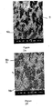
- Metallographic examination revealed the microstructure to be Mo particles embedded in a titanium matrix. Surrounding the Ti particles is an alloy phase of Mo dissolved in Ti.
- Figures 2A-2D show examples of the progression of increasing alloy phase with HIP temperature.
- Phase analysis of the samples to determine composition of the alloy was done using Energy Dispersive Spectroscopy on a Scanning Electron Microscope (SEM-EDS). The images, taken in the secondary electron mode, highlight the atomic number contrast. Titanium appears darkest, molybdenum appears lightest and the gray of the alloy phase is between the two. Although not readily detectable in these images, a compositional gradient exists in the alloy phase, with the highest Mo content found bordering the patches of Mo, and the lowest Mo is found adjacent to the Ti patches.
- the lightest gray phase in molybdenum shows only Mo and Ti. At 825°C, there is a third phase present.
- the lightest gray is Mo
- the darkest gray is Ti
- surrounding the Ti is an alloy phase that contains 10% to 20% Mo, by weight.
- At 925°C, very little pure Ti remains, and at 1038°C the microstructure comprises Mo and an alloy of Ti with about 25% Mo by weight.
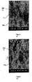
- Microstructure and density vs. HIP temperature indicated that the optimum temperature for the first HIP may be in the range of 720°C to 780°C.
- Three additional runs were made at 725°, 750° and 780°C, all for eight hours at 103 MPa (15,000 psi). These were evaluated for density, microstructure, hardness and alloy phase composition. Results of those tests show an improvement in densification over that predicted from the plot of density and temperature for the four-hour runs made previously. SEM photomicrographs for these runs are shown in Figures 3A-3D .
- HIP for four hours at 750°C and 103 MPa (15,000 psi) resulted in a density of 7.07 g/cc.
- Table 2 Densification response at 103 MPa (15,000 psi) for 8 hours HIP temperature 725°C 750°C 780°C Density (g/cc) 7.05 7.11 7.14
- Blended Mo and Ti powders at a ratio of 50 atomic percent each were cold isostatically pressed to approximately 65% to 75% theoretical density to form a block approximately 15.24 cm (6-in.) by 15.24 cm (6-in.) by 50.8 cm (20-in.) and encapsulated in a steel can using methods known in the art.
- the powder-filled can was hot isostatically pressed for four hours at 103 MPa (15,000 psi) and 750°C.
- the consolidated compact was removed from the steel can and cut into slices approximately 13.97 cm (51 ⁇ 2-in.) by 13.97 cm (51 ⁇ 2-in.) by 2.54 cm (1-in.).
- Magnetron sputtering was used as a means for deposition of molybdenum-titanium thin films onto substrates such as glass, silicon wafers and stainless steel.
- the chamber was pumped down to pressures lower than 5 ⁇ 10 -6 Torr and filled with argon to 6.5 ⁇ 10 -3 Torr for sputter etching of the surface.
- a negative voltage of 400V pulsing at 100 kHz was applied to the substrate for 30 minutes, accelerating argon ions to the substrate.
- the argon flow was reduced to 0.27 Pa (2 ⁇ 10 -3 Torr; 2 mTorr) and the target was sputter cleaned at 500W (DC) for 5 minutes.
- the deposition on the substrates was performed on the power mode (fixed power applied to the target) under different conditions where: gas pressure and time were varied. Table 4 lists the parameters employed. Table 4. Parameters for deposition at 1000W, with substrate at 0V, grounded. Time Gas Pressure (Pa; mTorr) 0.133 (1) 0.267 (2) 0.400 (3) 0.533 (4) 0.667 (5) 1 h X X X X ⁇ 2 min X X X 3. Substrate Source Spacing (SSS) : SSS was maintained at 12.7 cm (5"). 4. Deposition Rate . The deposition rates of Mo-Ti coatings on Si and Corning 1737 glass substrates were determined by the film cross-section thickness as measured with SEM. Table 5.
- Mo-Ti coatings on Corning 1737 glass with thickness around 200nm demonstrated much better adhesion than those coatings on stainless steel and soda lime glass substrates with thickness around 5 ⁇ m, possibly due to better chemical bonding and smaller total stress.
- Table 6a Tape test results of Mo-Ti coatings with thickness around 200nm on Corning 1737 glass substrates 0.133 Pa (1 mTorr) 0.400 Pa (3 mTorr) 0.667 Pa (5 mTorr) Target Mo-Ti 5B 5B 5B Table 6b. Tape test results of Mo-Ti coatings with thickness around 5 ⁇ m on stainless steel and soda lime substrates.
- Mo-Ti coatings became denser. Coatings on Corning 1737 glass substrates were denser than on Si substrates. Mo-Ti coatings on Corning 1737 glass with thickness around 200nm demonstrated much better adhesion than those coatings on stainless steel and soda lime glass substrates with thickness around 5 ⁇ m, possibly due to better chemical bonding and smaller total stress. Etch rates of Mo-Ti coatings were much lower than those of pure Mo coatings. The resistivity of Mo-Ti coatings were higher than those of pure Mo coatings. The uniformity of Mo-Ti is comparable to previous pure Mo coatings.
Landscapes
- Chemical & Material Sciences (AREA)
- Engineering & Computer Science (AREA)
- Mechanical Engineering (AREA)
- Materials Engineering (AREA)
- Manufacturing & Machinery (AREA)
- Chemical Kinetics & Catalysis (AREA)
- Metallurgy (AREA)
- Organic Chemistry (AREA)
- Composite Materials (AREA)
- Physical Vapour Deposition (AREA)
- Powder Metallurgy (AREA)
- Electrodes Of Semiconductors (AREA)
Claims (15)
- Verfahren zum Bonden von zwei oder mehreren Sputtertarget-Platten miteinander, um ein großflächiges Sputtertarget herzustellen, wobei das Verfahren umfasst:(a) Reinigen einer Kante von jeder der zwei oder mehreren Sputtertarget-Platten;(b) gegebenenfalls Bereitstellen eines Bonding-Materials auf einer Kante von mindestens einer der zwei oder mehreren zu bondenden Sputtertarget-Platten;(c) Verkapseln der zwei oder mehreren Sputtertarget-Platten; und(d) Verdichten, während die zwei oder mehreren Sputtertarget-Platten erwärmt werden, um eine großflächige Sputtertarget-Platte herzustellen, wobei der Schritt des Verdichtens während des Erwärmens isostatisches Heiß-Pressen bei einem Druck von 75 bis 300 MPa und einer Temperatur von 700°C bis 950°C ist; und das großflächige Sputtertarget mindestens 1397 mm (55 Inch) mal 1701,8 mm (67 Inch) in der Fläche ist; wobei jede der Sputtertarget-Platten Molybdän beinhaltet.
- Verfahren nach Anspruch 1, wobei jede der zwei oder mehreren Sputtertarget-Platten eine Dicke von 12,7 mm (0,5 Inch) bis 914,4 mm (36 Inch) entlang der zu bondenden Kante aufweist.
- Verfahren nach Anspruch 1 oder 2, wobei jede der zwei oder mehreren Sputtertarget-Platten eine Dicke von 101,6 mm (4 Inch) bis 203,2 mm (8 Inch) entlang der zu bondenden Kante aufweist.
- Verfahren nach einem der Ansprüche 1 bis 3, wobei die Sputtertarget-Platten aus Molybdän und Titan bestehen.
- Verfahren nach Anspruch 4, wobei ein Bonding-Material aus Titan-Pulver verwendet wird.
- Verfahren nach Anspruch 4, wobei ein Bonding-Material aus Titanfolie verwendet wird.
- Verfahren nach Anspruch 4, wobei ein Bonding-Material aus Titan-Molybdän-Pulver verwendet wird.
- Verfahren nach einem der Ansprüche 4 bis 7, wobei das großflächige Sputtertarget 5 bis 95 Atomprozent Titan, vorzugsweise 40 bis 60 Atomprozent Titan, beinhaltet.
- Verfahren nach einem der Ansprüche 1 bis 8, wobei das Verfahren das Herstellen jeder der Sputtertarget-Platten beinhaltet, umfassend:(i) Bereitstellen von Pulvern aus Molybdän und Titan, wobei das Titan-Pulver eine Menge von 40 bis 60 Atomprozent, bezogen auf die gesamten Atomprozent der Molybdän- und Titan-Pulver, darstellt, wobei der Rest Molybdän-Pulver ist;(ii) Mischen der Molybdän- und Titan-Pulver, um ein gemischtes Pulver herzustellen;(iii) gegebenenfalls Verfestigung des gemischten Pulvers;(iv) Einkapseln des verfestigten Pulvers; und(v) Verdichten unter Erwärmen des eingekapselten Pulvers, um die Sputtertarget-Platte aus Molybdän und Titan herzustellen.
- Verfahren zur Herstellung eines Molybdän-Titan-Sputtertargets, umfassend die Schritte von:(i) Bereitstellen von Pulvern aus Molybdän und Titan, wobei das Titan-Pulver eine Menge von 5 bis 95 Atomprozent, bezogen auf die gesamten Atomprozent der Molybdän- und Titan-Pulver, ist, wobei der Rest Molybdän-Pulver ist;(ii) Mischen der Molybdän- und Titan-Pulver, um ein gemischtes Pulver herzustellen;(iii) gegebenenfalls Verfestigung des gemischten Pulvers;(iv) Einkapseln des verfestigten Pulvers;(v) Verdichten unter Erwärmen des eingekapselten Pulvers, um eine erste MoTi-Targetplatte herzustellen,(vi) Entfernen eines Anteils der Einkapselung auf der ersten Sputtertarget-Platte;(vii) Bonden der ersten Sputtertarget-Platte mit einer zweiten MoTi-Sputtertarget-Platte entlang einer Kante der ersten und zweiten Sputtertarget-Platten, um gebondete Platten herzustellen; und(viii) Verdichten unter Erwärmen der gebondeten Platten, um eine gebondete Targetplatte herzustellen, wobei das Verdichten bei einem Druck von 75 bis 300 MPa durchgeführt wird und das Erwärmen bei einer Temperatur von 700 bis 950°C für einen Zeitraum von 2 bis 16 Stunden ausgeführt wird.
- Verfahren nach Anspruch 10, wobei(i) der Schritt (v) des Verdichtens während des Erwärmens bei einem Druck von 75 bis 300 MPa, vorzugsweise 100 bis 175 MPa, durchgeführt wird und das Erwärmen bei einer Temperatur von 725 bis 925°C, vorzugsweise 750 bis 850°C, für einen Zeitraum von 2 bis 16 Stunden, vorzugsweise 4 bis 8 Stunden, ausgeführt wird,
und/oder(ii) der Schritt (viii) des Verdichtens während des Erwärmens bei einem Druck von 75 bis 175 MPa durchgeführt wird und das Erwärmen bei einer Temperatur von 750 bis 850°C für einen Zeitraum von 2 bis 16 Stunden ausgeführt wird. - Verfahren nach einem der Ansprüche 9 bis 11, wobei das Molybdän-Pulver eine mittlere Teilchengröße von 2 bis 150 Mikrometer, bevorzugter 10 bis 30 Mikrometer, aufweist und das Titan-Pulver eine mittlere Teilchengröße von 50 bis 150 Mikrometer, bevorzugter 40 bis 60 Mikrometer, aufweist.
- Verfahren nach einem der Ansprüche 9 bis 11, wobei das Molybdän-Pulver eine mittlere Teilchengröße von 0,1 bis 25 Mikrometer, bevorzugter weniger als 5 Mikrometer, aufweist und das Titan-Pulver eine mittlere Teilchengröße von 5 bis 50 Mikrometer, bevorzugter 25 bis 35 Mikrometer, aufweist.
- Verfahren nach einem der Ansprüche 9 bis 13, wobei(i) das Verfahren den Schritt der Verfestigung (iii) beinhaltet, und der Schritt der Verfestigung in einer isostatischen Kalt-Presse auf eine Dichte von 60 bis 85 Prozent der theoretischen Dichte durchgeführt wird;
und/oder(ii) die gebondete Targetplatte mindestens 1397 mm (55 Inch) mal 1701,8 mm (67 Inch) in der Fläche beträgt
und/oder(iii) das Sputtertarget im Wesentlichen keine β(Ti,Mo)-Legierungsphase aufweist
und/oder(iv) die aus Schritt (v) erhaltene Targetplatte eine Dichte von mehr als 90 % der theoretischen Dichte aufweist. - Molybdän-Titan-Sputtertarget, hergestellt nach dem Verfahren nach einem der Ansprüche 1 bis 14.
Applications Claiming Priority (3)
| Application Number | Priority Date | Filing Date | Title |
|---|---|---|---|
| US11/255,018 US7837929B2 (en) | 2005-10-20 | 2005-10-20 | Methods of making molybdenum titanium sputtering plates and targets |
| EP06825961A EP1948376B1 (de) | 2005-10-20 | 2006-10-16 | Verfahren zur herstellung von molybdäntitansputterplatten und -targets |
| PCT/US2006/040214 WO2007047511A2 (en) | 2005-10-20 | 2006-10-16 | Methods of making molybdenum titanium sputtering plates and targets |
Related Parent Applications (2)
| Application Number | Title | Priority Date | Filing Date |
|---|---|---|---|
| EP06825961A Division EP1948376B1 (de) | 2005-10-20 | 2006-10-16 | Verfahren zur herstellung von molybdäntitansputterplatten und -targets |
| EP06825961.3 Division | 2006-10-16 |
Publications (2)
| Publication Number | Publication Date |
|---|---|
| EP2316595A1 EP2316595A1 (de) | 2011-05-04 |
| EP2316595B1 true EP2316595B1 (de) | 2019-01-02 |
Family
ID=37872773
Family Applications (2)
| Application Number | Title | Priority Date | Filing Date |
|---|---|---|---|
| EP10194969.1A Not-in-force EP2316595B1 (de) | 2005-10-20 | 2006-10-16 | Verfahren zur herstellung von molybden titan sputtertarget und sputtertarget |
| EP06825961A Not-in-force EP1948376B1 (de) | 2005-10-20 | 2006-10-16 | Verfahren zur herstellung von molybdäntitansputterplatten und -targets |
Family Applications After (1)
| Application Number | Title | Priority Date | Filing Date |
|---|---|---|---|
| EP06825961A Not-in-force EP1948376B1 (de) | 2005-10-20 | 2006-10-16 | Verfahren zur herstellung von molybdäntitansputterplatten und -targets |
Country Status (10)
| Country | Link |
|---|---|
| US (3) | US7837929B2 (de) |
| EP (2) | EP2316595B1 (de) |
| JP (1) | JP5376952B2 (de) |
| KR (2) | KR101370189B1 (de) |
| CN (1) | CN101360576A (de) |
| AT (1) | ATE508823T1 (de) |
| BR (1) | BRPI0617512A2 (de) |
| RU (1) | RU2008119466A (de) |
| TW (1) | TWI415952B (de) |
| WO (1) | WO2007047511A2 (de) |
Families Citing this family (45)
| Publication number | Priority date | Publication date | Assignee | Title |
|---|---|---|---|---|
| US20030002043A1 (en) * | 2001-04-10 | 2003-01-02 | Kla-Tencor Corporation | Periodic patterns and technique to control misalignment |
| CN101368262B (zh) * | 2005-05-05 | 2012-06-06 | H.C.施塔克有限公司 | 向表面施加涂层的方法 |
| US7837929B2 (en) * | 2005-10-20 | 2010-11-23 | H.C. Starck Inc. | Methods of making molybdenum titanium sputtering plates and targets |
| JP5210498B2 (ja) * | 2006-04-28 | 2013-06-12 | 株式会社アルバック | 接合型スパッタリングターゲット及びその作製方法 |
| US20080067058A1 (en) * | 2006-09-15 | 2008-03-20 | Stimson Bradley O | Monolithic target for flat panel application |
| US20080078268A1 (en) | 2006-10-03 | 2008-04-03 | H.C. Starck Inc. | Process for preparing metal powders having low oxygen content, powders so-produced and uses thereof |
| US20080087866A1 (en) * | 2006-10-13 | 2008-04-17 | H.C. Stark Inc. | Titanium oxide-based sputtering target for transparent conductive film, method for producing such film and composition for use therein |
| US20080145688A1 (en) | 2006-12-13 | 2008-06-19 | H.C. Starck Inc. | Method of joining tantalum clade steel structures |
| US8784729B2 (en) * | 2007-01-16 | 2014-07-22 | H.C. Starck Inc. | High density refractory metals and alloys sputtering targets |
| JP2008255440A (ja) * | 2007-04-06 | 2008-10-23 | Hitachi Metals Ltd | MoTi合金スパッタリングターゲット材 |
| US8197894B2 (en) | 2007-05-04 | 2012-06-12 | H.C. Starck Gmbh | Methods of forming sputtering targets |
| US8197885B2 (en) * | 2008-01-11 | 2012-06-12 | Climax Engineered Materials, Llc | Methods for producing sodium/molybdenum power compacts |
| JP2011523978A (ja) * | 2008-04-28 | 2011-08-25 | ハー ツェー シュタルク インコーポレイテッド | モリブデン−ニオブ合金、かかる合金を含有するスパッタリングターゲット、かかるターゲットの製造方法、それから製造される薄膜、およびその使用 |
| US8246903B2 (en) | 2008-09-09 | 2012-08-21 | H.C. Starck Inc. | Dynamic dehydriding of refractory metal powders |
| JP2011089188A (ja) * | 2009-10-26 | 2011-05-06 | Ulvac Japan Ltd | チタン含有スパッタリングターゲットの製造方法 |
| US8449817B2 (en) | 2010-06-30 | 2013-05-28 | H.C. Stark, Inc. | Molybdenum-containing targets comprising three metal elements |
| US8449818B2 (en) | 2010-06-30 | 2013-05-28 | H. C. Starck, Inc. | Molybdenum containing targets |
| KR20140015367A (ko) | 2011-02-14 | 2014-02-06 | 토소우 에스엠디, 인크 | 확산-접합 스퍼터링 타겟 조립체 및 그 제조 방법 |
| KR20160021299A (ko) | 2011-05-10 | 2016-02-24 | 에이치. 씨. 스타아크 아이앤씨 | 멀티-블록 스퍼터링 타겟 및 이에 관한 제조방법 및 물품 |
| KR101338688B1 (ko) * | 2011-06-02 | 2013-12-06 | 엘지이노텍 주식회사 | 태양전지 및 그의 제조방법 |
| CN102321871B (zh) * | 2011-09-19 | 2013-03-20 | 基迈克材料科技(苏州)有限公司 | 热等静压生产平板显示器用钼合金溅射靶材的方法 |
| TWI572725B (zh) * | 2011-09-26 | 2017-03-01 | 日立金屬股份有限公司 | MoTi靶材的製造方法 |
| US9412568B2 (en) | 2011-09-29 | 2016-08-09 | H.C. Starck, Inc. | Large-area sputtering targets |
| US9334565B2 (en) * | 2012-05-09 | 2016-05-10 | H.C. Starck Inc. | Multi-block sputtering target with interface portions and associated methods and articles |
| CN102922225B (zh) * | 2012-08-16 | 2015-05-06 | 宁夏东方钽业股份有限公司 | 一种钼靶材的制备方法 |
| CN103060760A (zh) * | 2012-11-28 | 2013-04-24 | 厦门虹鹭钨钼工业有限公司 | 一种钼钛合金靶材的制备方法 |
| CN103071793B (zh) * | 2013-02-01 | 2015-07-22 | 基迈克材料科技(苏州)有限公司 | 钼溅射靶材热等静压生产方法 |
| CN104708192A (zh) * | 2013-12-12 | 2015-06-17 | 有研亿金新材料有限公司 | 一种W-Ti合金靶材组件扩散焊接方法 |
| US9988698B2 (en) * | 2013-12-13 | 2018-06-05 | The Abbott Ball Company | Method of hardening articles and articles comprising the same |
| KR101605633B1 (ko) | 2014-09-30 | 2016-04-01 | 희성금속 주식회사 | 반도체용 탄탈럼 타겟의 제조방법 및 이로부터 제조된 탄탈럼 스퍼터링 타겟 |
| CN104532201B (zh) * | 2014-12-29 | 2017-03-15 | 金堆城钼业股份有限公司 | 一种钼钛合金溅射靶材板的制备方法 |
| CN104480446A (zh) * | 2014-12-30 | 2015-04-01 | 山东昊轩电子陶瓷材料有限公司 | 钼钛合金靶材及其生产方法 |
| CN104694774B (zh) * | 2015-03-19 | 2017-12-08 | 中国工程物理研究院材料研究所 | 一种高致密度细晶钛合金的热等静压制备方法 |
| CN106148903A (zh) * | 2015-04-22 | 2016-11-23 | 宁波江丰电子材料股份有限公司 | 钼钛靶材的制造方法 |
| CN105087982B (zh) * | 2015-08-20 | 2017-03-15 | 金堆城钼业股份有限公司 | 一种MoTa/MoTi合金粉末的制备方法 |
| CN106475566A (zh) * | 2015-08-27 | 2017-03-08 | 宁波江丰电子材料股份有限公司 | 钼钛靶坯的制造方法 |
| CN105773074B (zh) * | 2016-03-14 | 2017-08-18 | 洛阳高新四丰电子材料有限公司 | 一种钼合金舟的制作方法 |
| JP6868426B2 (ja) | 2016-03-29 | 2021-05-12 | 東北特殊鋼株式会社 | チタン合金製コーティング膜及びその製造方法、並びにチタン合金製ターゲット材の製造方法 |
| WO2017170639A1 (ja) * | 2016-03-29 | 2017-10-05 | 大同特殊鋼株式会社 | チタン合金製コーティング膜及びチタン合金製ターゲット材 |
| US11286172B2 (en) | 2017-02-24 | 2022-03-29 | BWXT Isotope Technology Group, Inc. | Metal-molybdate and method for making the same |
| US10975464B2 (en) * | 2018-04-09 | 2021-04-13 | International Business Machines Corporation | Hard mask films with graded vertical concentration formed using reactive sputtering in a radio frequency deposition chamber |
| CN110952064A (zh) * | 2019-11-25 | 2020-04-03 | 宁波江丰电子材料股份有限公司 | 一种钽硅合金溅射靶材及其制备方法 |
| CN113600815A (zh) * | 2021-06-24 | 2021-11-05 | 厦门虹鹭钨钼工业有限公司 | 一种干式掺杂钼合金的制备方法 |
| CN114540778A (zh) * | 2022-01-14 | 2022-05-27 | 西安理工大学 | Ti-Mo合金薄膜及其制备方法 |
| CN119140822A (zh) * | 2024-10-31 | 2024-12-17 | 宁波江丰电子材料股份有限公司 | 一种MoTi合金靶材的制备方法 |
Family Cites Families (96)
| Publication number | Priority date | Publication date | Assignee | Title |
|---|---|---|---|---|
| US787929A (en) * | 1904-09-08 | 1905-04-25 | Sumter Telephone Mmfg Company | Telephone-switchboard. |
| US2678270A (en) * | 1951-10-06 | 1954-05-11 | Climax Molybdenum Co | Molybdenum-tantalum alloys |
| US2678268A (en) * | 1951-10-06 | 1954-05-11 | Climax Molybdenum Co | Molybdenum-vanadium alloys |
| US2678269A (en) * | 1951-10-06 | 1954-05-11 | Climax Molybdenum Co | Molybdenum-titanium alloys |
| US3841846A (en) * | 1970-01-25 | 1974-10-15 | Mallory & Co Inc P R | Liquid phase sintered molybdenum base alloys having additives and shaping members made therefrom |
| US3714702A (en) * | 1971-08-17 | 1973-02-06 | Atomic Energy Commission | Method for diffusion bonding refractory metals and alloys |
| DE2522690C3 (de) * | 1975-05-22 | 1982-03-04 | Goetze Ag, 5093 Burscheid | Plasmaauftragsschweißpulver für die Herstellung verschleißfester Schichten |
| JPS5496775A (en) | 1978-01-17 | 1979-07-31 | Hitachi Ltd | Method of forming circuit |
| US4594219A (en) * | 1985-08-02 | 1986-06-10 | Metals, Ltd. | Powder metal consolidation of multiple preforms |
| US4647426A (en) * | 1985-12-23 | 1987-03-03 | Battelle Memorial Institute | Production of billet and extruded products from particulate materials |
| US4747907A (en) * | 1986-10-29 | 1988-05-31 | International Business Machines Corporation | Metal etching process with etch rate enhancement |
| JPH0791636B2 (ja) * | 1987-03-09 | 1995-10-04 | 日立金属株式会社 | スパツタリングタ−ゲツトおよびその製造方法 |
| JPS63241164A (ja) | 1987-03-30 | 1988-10-06 | Toshiba Corp | スパッタリングターゲットおよび電気配線用合金膜 |
| US4820393A (en) | 1987-05-11 | 1989-04-11 | Tosoh Smd, Inc. | Titanium nitride sputter targets |
| DE3718779A1 (de) * | 1987-06-04 | 1988-12-22 | Krauss Maffei Ag | Schnecke od. dgl. maschinenteil fuer kunststoffverarbeitende maschinen |
| US5294321A (en) * | 1988-12-21 | 1994-03-15 | Kabushiki Kaisha Toshiba | Sputtering target |
| US4931253A (en) * | 1989-08-07 | 1990-06-05 | United States Of America As Represented By The Secretary Of The Air Force | Method for producing alpha titanium alloy pm articles |
| US4995942A (en) * | 1990-04-30 | 1991-02-26 | International Business Machines Corporation | Effective near neutral pH etching solution for molybdenum or tungsten |
| JPH04333565A (ja) * | 1991-01-17 | 1992-11-20 | Mitsubishi Materials Corp | スパッタリングターゲットおよびその製造方法 |
| JPH0539566A (ja) | 1991-02-19 | 1993-02-19 | Mitsubishi Materials Corp | スパツタリング用ターゲツト及びその製造方法 |
| US5292423A (en) | 1991-04-09 | 1994-03-08 | New Mexico State University Technology Transfer Corp. | Method and apparatus for trace metal testing |
| US5234487A (en) * | 1991-04-15 | 1993-08-10 | Tosoh Smd, Inc. | Method of producing tungsten-titanium sputter targets and targets produced thereby |
| TW234767B (zh) | 1992-09-29 | 1994-11-21 | Nippon En Kk | 擴散接合之噴濺靶組立體及其製法 |
| JPH06264233A (ja) | 1993-03-12 | 1994-09-20 | Nikko Kinzoku Kk | Tft製造用スパッタリングタ−ゲット |
| US5429877A (en) | 1993-10-20 | 1995-07-04 | The United States Of America As Represented By The Secretary Of The Air Force | Internally reinforced hollow titanium alloy components |
| US5397050A (en) | 1993-10-27 | 1995-03-14 | Tosoh Smd, Inc. | Method of bonding tungsten titanium sputter targets to titanium plates and target assemblies produced thereby |
| US5693156A (en) * | 1993-12-21 | 1997-12-02 | United Technologies Corporation | Oxidation resistant molybdenum alloy |
| US5518131A (en) * | 1994-07-07 | 1996-05-21 | International Business Machines Corporation | Etching molydbenum with ferric sulfate and ferric ammonium sulfate |
| US5857611A (en) | 1995-08-16 | 1999-01-12 | Sony Corporation | Sputter target/backing plate assembly and method of making same |
| EP1452622A3 (de) * | 1995-08-23 | 2004-09-29 | Asahi Glass Ceramics Co., Ltd. | Target, Verfahren zu dessen Herstellung und Herstellung hochrefraktiver Filme |
| US5896553A (en) | 1996-04-10 | 1999-04-20 | Sony Corporation | Single phase tungsten-titanium sputter targets and method of producing same |
| US5963778A (en) | 1997-02-13 | 1999-10-05 | Tosoh Smd, Inc. | Method for producing near net shape planar sputtering targets and an intermediate therefor |
| US6185413B1 (en) * | 1997-06-17 | 2001-02-06 | Siemens Aktiengesellschaft | Mobile station having a cost-efficient call management method and system |
| JP3629954B2 (ja) | 1997-06-17 | 2005-03-16 | ヤマハ株式会社 | 半導体装置及びその製造方法 |
| US20030052000A1 (en) * | 1997-07-11 | 2003-03-20 | Vladimir Segal | Fine grain size material, sputtering target, methods of forming, and micro-arc reduction method |
| US5895663A (en) | 1997-07-31 | 1999-04-20 | L. Perrigo Company | Pseudoephedrine hydrochloride extended-release tablets |
| JP2989169B2 (ja) * | 1997-08-08 | 1999-12-13 | 日立金属株式会社 | Ni−Al系金属間化合物ターゲットおよびその製造方法ならびに磁気記録媒体 |
| US6010583A (en) | 1997-09-09 | 2000-01-04 | Sony Corporation | Method of making unreacted metal/aluminum sputter target |
| JPH1180942A (ja) | 1997-09-10 | 1999-03-26 | Japan Energy Corp | Taスパッタターゲットとその製造方法及び組立体 |
| JP4002659B2 (ja) | 1998-03-04 | 2007-11-07 | アルプス電気株式会社 | IrMn系合金成膜用ターゲット、およびそれを用いた反強磁性膜 |
| US6183686B1 (en) | 1998-08-04 | 2001-02-06 | Tosoh Smd, Inc. | Sputter target assembly having a metal-matrix-composite backing plate and methods of making same |
| US6071389A (en) | 1998-08-21 | 2000-06-06 | Tosoh Smd, Inc. | Diffusion bonded sputter target assembly and method of making |
| KR20010080499A (ko) | 1998-12-03 | 2001-08-22 | 추후제출 | 삽입체 타겟 조립체 및 그 제조 방법 |
| US6328927B1 (en) | 1998-12-24 | 2001-12-11 | Praxair Technology, Inc. | Method of making high-density, high-purity tungsten sputter targets |
| US6521108B1 (en) | 1998-12-29 | 2003-02-18 | Tosoh Smd, Inc. | Diffusion bonded sputter target assembly and method of making same |
| US6726787B2 (en) | 1999-01-07 | 2004-04-27 | Jiin-Huey Chern Lin | Process for making a work piece having a major phase of α from a titanium alloy |
| US20040159374A1 (en) * | 1999-01-07 | 2004-08-19 | Jiin-Huey Chern Lin | Titanium alloy composition having a major phase of alpha" |
| JP2000239838A (ja) | 1999-02-15 | 2000-09-05 | Sony Corp | 固相拡散接合されたスパッタリングターゲット組立体およびその製造方法 |
| TWI255957B (en) * | 1999-03-26 | 2006-06-01 | Hitachi Ltd | Liquid crystal display device and method of manufacturing the same |
| US6165413A (en) | 1999-07-08 | 2000-12-26 | Praxair S.T. Technology, Inc. | Method of making high density sputtering targets |
| US6042777A (en) | 1999-08-03 | 2000-03-28 | Sony Corporation | Manufacturing of high density intermetallic sputter targets |
| US6199747B1 (en) * | 1999-08-30 | 2001-03-13 | International Business Machines Corporation | High temperature refractory joining paste |
| KR20020068535A (ko) | 1999-11-22 | 2002-08-27 | 가부시키 가이샤 닛코 마테리알즈 | 스퍼터링용 티타늄 타겟트 |
| US6619537B1 (en) | 2000-06-12 | 2003-09-16 | Tosoh Smd, Inc. | Diffusion bonding of copper sputtering targets to backing plates using nickel alloy interlayers |
| CN1370853A (zh) | 2001-02-23 | 2002-09-25 | 光洋应用材料科技股份有限公司 | 金属溅镀靶材的制造方法 |
| US20030029728A1 (en) * | 2001-07-18 | 2003-02-13 | Benjamin Scharifker | Process to separate the vanadium contained in inorganic acid solutions |
| JP3748221B2 (ja) | 2001-10-23 | 2006-02-22 | 日立金属株式会社 | Mo系スパッタリング用ターゲットおよびその製造方法 |
| JP4312431B2 (ja) * | 2001-11-30 | 2009-08-12 | 新日鉄マテリアルズ株式会社 | ターゲット材 |
| US6638381B2 (en) | 2001-12-18 | 2003-10-28 | The Boeing Company | Method for preparing ultra-fine grain titanium and titanium-alloy articles and articles prepared thereby |
| JP2003342720A (ja) * | 2002-05-20 | 2003-12-03 | Nippon Steel Corp | スパッタリング用モリブデンターゲットの製造方法及びモリブデンターゲット |
| US20040009087A1 (en) * | 2002-07-10 | 2004-01-15 | Wuwen Yi | Physical vapor deposition targets, and methods of forming physical vapor deposition targets |
| CN1723292A (zh) * | 2002-12-09 | 2006-01-18 | 霍尼韦尔国际公司 | 高纯镍/钒溅射构件和制备溅射构件的方法 |
| JP2004204253A (ja) | 2002-12-24 | 2004-07-22 | Hitachi Metals Ltd | ターゲット |
| JP4574949B2 (ja) | 2003-01-14 | 2010-11-04 | 株式会社東芝 | スパッタリングターゲットとその製造方法 |
| JP4422975B2 (ja) | 2003-04-03 | 2010-03-03 | 株式会社コベルコ科研 | スパッタリングターゲットおよびその製造方法 |
| TW586336B (en) * | 2003-06-30 | 2004-05-01 | Ritdisplay Corp | Electrode substrate of flat panel display |
| JP4415303B2 (ja) | 2003-07-10 | 2010-02-17 | 日立金属株式会社 | 薄膜形成用スパッタリングターゲット |
| JP2005097697A (ja) | 2003-09-26 | 2005-04-14 | Toshiba Corp | スパッタリングターゲットとその製造方法 |
| US7336336B2 (en) * | 2003-10-14 | 2008-02-26 | Lg. Philips Co. Ltd. | Thin film transistor array substrate, method of fabricating the same, liquid crystal display panel having the same and fabricating method thereof |
| JP4407243B2 (ja) * | 2003-11-10 | 2010-02-03 | ソニー株式会社 | 照合処理装置とその方法 |
| KR101012491B1 (ko) | 2003-12-04 | 2011-02-08 | 엘지디스플레이 주식회사 | 액정표시장치용 어레이기판과 제조방법 |
| US7832619B2 (en) | 2004-02-27 | 2010-11-16 | Howmet Corporation | Method of making sputtering target |
| JP4110533B2 (ja) * | 2004-02-27 | 2008-07-02 | 日立金属株式会社 | Mo系ターゲット材の製造方法 |
| US20050230244A1 (en) | 2004-03-31 | 2005-10-20 | Hitachi Metals, Ltd | Sputter target material and method of producing the same |
| US8252126B2 (en) | 2004-05-06 | 2012-08-28 | Global Advanced Metals, Usa, Inc. | Sputter targets and methods of forming same by rotary axial forging |
| US20050279630A1 (en) | 2004-06-16 | 2005-12-22 | Dynamic Machine Works, Inc. | Tubular sputtering targets and methods of flowforming the same |
| US20060042728A1 (en) * | 2004-08-31 | 2006-03-02 | Brad Lemon | Molybdenum sputtering targets |
| KR101061850B1 (ko) * | 2004-09-08 | 2011-09-02 | 삼성전자주식회사 | 박막 트랜지스터 표시판 및 그 제조방법 |
| JP4596878B2 (ja) | 2004-10-14 | 2010-12-15 | キヤノン株式会社 | 構造体、電子放出素子、2次電池、電子源、画像表示装置、情報表示再生装置及びそれらの製造方法 |
| CN101368262B (zh) * | 2005-05-05 | 2012-06-06 | H.C.施塔克有限公司 | 向表面施加涂层的方法 |
| US7837929B2 (en) | 2005-10-20 | 2010-11-23 | H.C. Starck Inc. | Methods of making molybdenum titanium sputtering plates and targets |
| KR20070049278A (ko) * | 2005-11-08 | 2007-05-11 | 삼성전자주식회사 | 배선, 이를 포함하는 박막 트랜지스터 기판과 그 제조 방법 |
| JP5210498B2 (ja) * | 2006-04-28 | 2013-06-12 | 株式会社アルバック | 接合型スパッタリングターゲット及びその作製方法 |
| US20070289864A1 (en) * | 2006-06-15 | 2007-12-20 | Zhifei Ye | Large Area Sputtering Target |
| US20080118031A1 (en) * | 2006-11-17 | 2008-05-22 | H.C. Starck Inc. | Metallic alloy for X-ray target |
| JP5426173B2 (ja) * | 2007-01-12 | 2014-02-26 | 新日鉄住金マテリアルズ株式会社 | Mo系スパッタリングターゲット板,および,その製造方法 |
| US20110303535A1 (en) * | 2007-05-04 | 2011-12-15 | Miller Steven A | Sputtering targets and methods of forming the same |
| US8197894B2 (en) * | 2007-05-04 | 2012-06-12 | H.C. Starck Gmbh | Methods of forming sputtering targets |
| US8250895B2 (en) * | 2007-08-06 | 2012-08-28 | H.C. Starck Inc. | Methods and apparatus for controlling texture of plates and sheets by tilt rolling |
| EP2185300B1 (de) * | 2007-08-06 | 2018-10-24 | H. C. Starck, Inc. | Refraktäre metallplatten mit verbesserter texturgleichmässigkeit |
| JP2011523978A (ja) | 2008-04-28 | 2011-08-25 | ハー ツェー シュタルク インコーポレイテッド | モリブデン−ニオブ合金、かかる合金を含有するスパッタリングターゲット、かかるターゲットの製造方法、それから製造される薄膜、およびその使用 |
| US8043655B2 (en) * | 2008-10-06 | 2011-10-25 | H.C. Starck, Inc. | Low-energy method of manufacturing bulk metallic structures with submicron grain sizes |
| US8449817B2 (en) * | 2010-06-30 | 2013-05-28 | H.C. Stark, Inc. | Molybdenum-containing targets comprising three metal elements |
| US8449818B2 (en) * | 2010-06-30 | 2013-05-28 | H. C. Starck, Inc. | Molybdenum containing targets |
| KR20160021299A (ko) | 2011-05-10 | 2016-02-24 | 에이치. 씨. 스타아크 아이앤씨 | 멀티-블록 스퍼터링 타겟 및 이에 관한 제조방법 및 물품 |
| US9334565B2 (en) * | 2012-05-09 | 2016-05-10 | H.C. Starck Inc. | Multi-block sputtering target with interface portions and associated methods and articles |
-
2005
- 2005-10-20 US US11/255,018 patent/US7837929B2/en not_active Expired - Lifetime
-
2006
- 2006-10-16 EP EP10194969.1A patent/EP2316595B1/de not_active Not-in-force
- 2006-10-16 EP EP06825961A patent/EP1948376B1/de not_active Not-in-force
- 2006-10-16 CN CNA2006800386829A patent/CN101360576A/zh active Pending
- 2006-10-16 US US12/090,919 patent/US20080314737A1/en not_active Abandoned
- 2006-10-16 WO PCT/US2006/040214 patent/WO2007047511A2/en not_active Ceased
- 2006-10-16 JP JP2008536705A patent/JP5376952B2/ja not_active Expired - Fee Related
- 2006-10-16 KR KR1020137014691A patent/KR101370189B1/ko not_active Expired - Fee Related
- 2006-10-16 BR BRPI0617512-0A patent/BRPI0617512A2/pt not_active Application Discontinuation
- 2006-10-16 AT AT06825961T patent/ATE508823T1/de active
- 2006-10-16 RU RU2008119466/02A patent/RU2008119466A/ru not_active Application Discontinuation
- 2006-10-16 KR KR1020087012051A patent/KR101365797B1/ko not_active Expired - Fee Related
- 2006-10-19 TW TW095138492A patent/TWI415952B/zh not_active IP Right Cessation
-
2010
- 2010-11-02 US US12/917,668 patent/US8911528B2/en active Active
Non-Patent Citations (1)
| Title |
|---|
| None * |
Also Published As
| Publication number | Publication date |
|---|---|
| US20110097236A1 (en) | 2011-04-28 |
| EP2316595A1 (de) | 2011-05-04 |
| KR20080064874A (ko) | 2008-07-09 |
| KR101370189B1 (ko) | 2014-03-05 |
| JP2009513823A (ja) | 2009-04-02 |
| WO2007047511A3 (en) | 2007-08-09 |
| RU2008119466A (ru) | 2009-11-27 |
| EP1948376A2 (de) | 2008-07-30 |
| CN101360576A (zh) | 2009-02-04 |
| KR20130079640A (ko) | 2013-07-10 |
| TW200720448A (en) | 2007-06-01 |
| EP1948376B1 (de) | 2011-05-11 |
| US20080314737A1 (en) | 2008-12-25 |
| US7837929B2 (en) | 2010-11-23 |
| WO2007047511A2 (en) | 2007-04-26 |
| BRPI0617512A2 (pt) | 2011-07-26 |
| KR101365797B1 (ko) | 2014-03-12 |
| US20070089984A1 (en) | 2007-04-26 |
| JP5376952B2 (ja) | 2013-12-25 |
| TWI415952B (zh) | 2013-11-21 |
| ATE508823T1 (de) | 2011-05-15 |
| US8911528B2 (en) | 2014-12-16 |
Similar Documents
| Publication | Publication Date | Title |
|---|---|---|
| EP2316595B1 (de) | Verfahren zur herstellung von molybden titan sputtertarget und sputtertarget | |
| US6521173B2 (en) | Low oxygen refractory metal powder for powder metallurgy | |
| US6676728B2 (en) | Sputtering target, method of making same, and high-melting metal powder material | |
| JP3445276B2 (ja) | 配線形成用Mo−WターゲットとMo−W配線薄膜、およびそれを用いた液晶表示装置 | |
| EP0345045A1 (de) | Verfahren zur Herstellung von Sputtertargets aus Wolfram-Titan | |
| WO2004009865A1 (en) | FABRICATION OF B/C/N/O/Si DOPED SPUTTERING TARGETS | |
| EP2277191A1 (de) | Molybdän-niob-legierungen, solche legierungen enthaltende sputtertargets, verfahren zur herstellung solcher targets, daraus hergestellte dünnfilme und verwendungen dafür | |
| JP2011504547A (ja) | 耐熱金属をドープしたスパッタリングターゲット | |
| US20070196563A1 (en) | Three-dimensional pvd targets, and methods of forming three-dimensional pvd targets | |
| JP4574949B2 (ja) | スパッタリングターゲットとその製造方法 | |
| US20040062675A1 (en) | Fabrication of ductile intermetallic sputtering targets | |
| JP2901049B2 (ja) | アークイオンプレーティング用Al−Ti合金ターゲット材 | |
| JP2950436B2 (ja) | 複合化材料の製造方法 | |
| JP4203180B2 (ja) | Ti−Al合金スパッタリングターゲット及びその製造方法 | |
| KR102316360B1 (ko) | 스퍼터링 타깃 및 제조방법 | |
| JP2000001732A (ja) | 配線形成用Mo―W材、配線形成用Mo―Wタ―ゲットとその製造方法、およびMo―W配線薄膜と液晶表示装置 | |
| CN116334563A (zh) | 溅射靶及制造溅射靶的方法 | |
| JP2003171760A (ja) | タングステンスパッタリングターゲット | |
| JPH02170969A (ja) | ターゲット材の製造方法 |
Legal Events
| Date | Code | Title | Description |
|---|---|---|---|
| PUAI | Public reference made under article 153(3) epc to a published international application that has entered the european phase |
Free format text: ORIGINAL CODE: 0009012 |
|
| 17P | Request for examination filed |
Effective date: 20101214 |
|
| AC | Divisional application: reference to earlier application |
Ref document number: 1948376 Country of ref document: EP Kind code of ref document: P |
|
| AK | Designated contracting states |
Kind code of ref document: A1 Designated state(s): AT BE BG CH CY CZ DE DK EE ES FI FR GB GR HU IE IS IT LI LT LU LV MC NL PL PT RO SE SI SK TR |
|
| 17Q | First examination report despatched |
Effective date: 20150701 |
|
| STAA | Information on the status of an ep patent application or granted ep patent |
Free format text: STATUS: EXAMINATION IS IN PROGRESS |
|
| GRAP | Despatch of communication of intention to grant a patent |
Free format text: ORIGINAL CODE: EPIDOSNIGR1 |
|
| STAA | Information on the status of an ep patent application or granted ep patent |
Free format text: STATUS: GRANT OF PATENT IS INTENDED |
|
| INTG | Intention to grant announced |
Effective date: 20180808 |
|
| GRAS | Grant fee paid |
Free format text: ORIGINAL CODE: EPIDOSNIGR3 |
|
| GRAA | (expected) grant |
Free format text: ORIGINAL CODE: 0009210 |
|
| STAA | Information on the status of an ep patent application or granted ep patent |
Free format text: STATUS: THE PATENT HAS BEEN GRANTED |
|
| AC | Divisional application: reference to earlier application |
Ref document number: 1948376 Country of ref document: EP Kind code of ref document: P |
|
| AK | Designated contracting states |
Kind code of ref document: B1 Designated state(s): AT BE BG CH CY CZ DE DK EE ES FI FR GB GR HU IE IS IT LI LT LU LV MC NL PL PT RO SE SI SK TR |
|
| REG | Reference to a national code |
Ref country code: GB Ref legal event code: FG4D |
|
| REG | Reference to a national code |
Ref country code: CH Ref legal event code: EP Ref country code: AT Ref legal event code: REF Ref document number: 1083722 Country of ref document: AT Kind code of ref document: T Effective date: 20190115 |
|
| REG | Reference to a national code |
Ref country code: DE Ref legal event code: R096 Ref document number: 602006057232 Country of ref document: DE |
|
| REG | Reference to a national code |
Ref country code: IE Ref legal event code: FG4D |
|
| REG | Reference to a national code |
Ref country code: NL Ref legal event code: MP Effective date: 20190102 |
|
| REG | Reference to a national code |
Ref country code: LT Ref legal event code: MG4D |
|
| PG25 | Lapsed in a contracting state [announced via postgrant information from national office to epo] |
Ref country code: NL Free format text: LAPSE BECAUSE OF FAILURE TO SUBMIT A TRANSLATION OF THE DESCRIPTION OR TO PAY THE FEE WITHIN THE PRESCRIBED TIME-LIMIT Effective date: 20190102 |
|
| PG25 | Lapsed in a contracting state [announced via postgrant information from national office to epo] |
Ref country code: PT Free format text: LAPSE BECAUSE OF FAILURE TO SUBMIT A TRANSLATION OF THE DESCRIPTION OR TO PAY THE FEE WITHIN THE PRESCRIBED TIME-LIMIT Effective date: 20190502 Ref country code: SE Free format text: LAPSE BECAUSE OF FAILURE TO SUBMIT A TRANSLATION OF THE DESCRIPTION OR TO PAY THE FEE WITHIN THE PRESCRIBED TIME-LIMIT Effective date: 20190102 Ref country code: FI Free format text: LAPSE BECAUSE OF FAILURE TO SUBMIT A TRANSLATION OF THE DESCRIPTION OR TO PAY THE FEE WITHIN THE PRESCRIBED TIME-LIMIT Effective date: 20190102 Ref country code: PL Free format text: LAPSE BECAUSE OF FAILURE TO SUBMIT A TRANSLATION OF THE DESCRIPTION OR TO PAY THE FEE WITHIN THE PRESCRIBED TIME-LIMIT Effective date: 20190102 Ref country code: LT Free format text: LAPSE BECAUSE OF FAILURE TO SUBMIT A TRANSLATION OF THE DESCRIPTION OR TO PAY THE FEE WITHIN THE PRESCRIBED TIME-LIMIT Effective date: 20190102 Ref country code: ES Free format text: LAPSE BECAUSE OF FAILURE TO SUBMIT A TRANSLATION OF THE DESCRIPTION OR TO PAY THE FEE WITHIN THE PRESCRIBED TIME-LIMIT Effective date: 20190102 |
|
| PG25 | Lapsed in a contracting state [announced via postgrant information from national office to epo] |
Ref country code: GR Free format text: LAPSE BECAUSE OF FAILURE TO SUBMIT A TRANSLATION OF THE DESCRIPTION OR TO PAY THE FEE WITHIN THE PRESCRIBED TIME-LIMIT Effective date: 20190403 Ref country code: BG Free format text: LAPSE BECAUSE OF FAILURE TO SUBMIT A TRANSLATION OF THE DESCRIPTION OR TO PAY THE FEE WITHIN THE PRESCRIBED TIME-LIMIT Effective date: 20190402 Ref country code: IS Free format text: LAPSE BECAUSE OF FAILURE TO SUBMIT A TRANSLATION OF THE DESCRIPTION OR TO PAY THE FEE WITHIN THE PRESCRIBED TIME-LIMIT Effective date: 20190502 Ref country code: LV Free format text: LAPSE BECAUSE OF FAILURE TO SUBMIT A TRANSLATION OF THE DESCRIPTION OR TO PAY THE FEE WITHIN THE PRESCRIBED TIME-LIMIT Effective date: 20190102 |
|
| REG | Reference to a national code |
Ref country code: DE Ref legal event code: R097 Ref document number: 602006057232 Country of ref document: DE |
|
| PG25 | Lapsed in a contracting state [announced via postgrant information from national office to epo] |
Ref country code: SK Free format text: LAPSE BECAUSE OF FAILURE TO SUBMIT A TRANSLATION OF THE DESCRIPTION OR TO PAY THE FEE WITHIN THE PRESCRIBED TIME-LIMIT Effective date: 20190102 Ref country code: IT Free format text: LAPSE BECAUSE OF FAILURE TO SUBMIT A TRANSLATION OF THE DESCRIPTION OR TO PAY THE FEE WITHIN THE PRESCRIBED TIME-LIMIT Effective date: 20190102 Ref country code: RO Free format text: LAPSE BECAUSE OF FAILURE TO SUBMIT A TRANSLATION OF THE DESCRIPTION OR TO PAY THE FEE WITHIN THE PRESCRIBED TIME-LIMIT Effective date: 20190102 Ref country code: CZ Free format text: LAPSE BECAUSE OF FAILURE TO SUBMIT A TRANSLATION OF THE DESCRIPTION OR TO PAY THE FEE WITHIN THE PRESCRIBED TIME-LIMIT Effective date: 20190102 Ref country code: EE Free format text: LAPSE BECAUSE OF FAILURE TO SUBMIT A TRANSLATION OF THE DESCRIPTION OR TO PAY THE FEE WITHIN THE PRESCRIBED TIME-LIMIT Effective date: 20190102 Ref country code: DK Free format text: LAPSE BECAUSE OF FAILURE TO SUBMIT A TRANSLATION OF THE DESCRIPTION OR TO PAY THE FEE WITHIN THE PRESCRIBED TIME-LIMIT Effective date: 20190102 |
|
| PLBE | No opposition filed within time limit |
Free format text: ORIGINAL CODE: 0009261 |
|
| STAA | Information on the status of an ep patent application or granted ep patent |
Free format text: STATUS: NO OPPOSITION FILED WITHIN TIME LIMIT |
|
| 26N | No opposition filed |
Effective date: 20191003 |
|
| PG25 | Lapsed in a contracting state [announced via postgrant information from national office to epo] |
Ref country code: SI Free format text: LAPSE BECAUSE OF FAILURE TO SUBMIT A TRANSLATION OF THE DESCRIPTION OR TO PAY THE FEE WITHIN THE PRESCRIBED TIME-LIMIT Effective date: 20190102 |
|
| PG25 | Lapsed in a contracting state [announced via postgrant information from national office to epo] |
Ref country code: TR Free format text: LAPSE BECAUSE OF FAILURE TO SUBMIT A TRANSLATION OF THE DESCRIPTION OR TO PAY THE FEE WITHIN THE PRESCRIBED TIME-LIMIT Effective date: 20190102 |
|
| PG25 | Lapsed in a contracting state [announced via postgrant information from national office to epo] |
Ref country code: MC Free format text: LAPSE BECAUSE OF FAILURE TO SUBMIT A TRANSLATION OF THE DESCRIPTION OR TO PAY THE FEE WITHIN THE PRESCRIBED TIME-LIMIT Effective date: 20190102 |
|
| REG | Reference to a national code |
Ref country code: CH Ref legal event code: PL |
|
| PG25 | Lapsed in a contracting state [announced via postgrant information from national office to epo] |
Ref country code: CH Free format text: LAPSE BECAUSE OF NON-PAYMENT OF DUE FEES Effective date: 20191031 Ref country code: LU Free format text: LAPSE BECAUSE OF NON-PAYMENT OF DUE FEES Effective date: 20191016 Ref country code: LI Free format text: LAPSE BECAUSE OF NON-PAYMENT OF DUE FEES Effective date: 20191031 |
|
| REG | Reference to a national code |
Ref country code: BE Ref legal event code: MM Effective date: 20191031 |
|
| PG25 | Lapsed in a contracting state [announced via postgrant information from national office to epo] |
Ref country code: BE Free format text: LAPSE BECAUSE OF NON-PAYMENT OF DUE FEES Effective date: 20191031 |
|
| GBPC | Gb: european patent ceased through non-payment of renewal fee |
Effective date: 20191016 |
|
| PG25 | Lapsed in a contracting state [announced via postgrant information from national office to epo] |
Ref country code: FR Free format text: LAPSE BECAUSE OF NON-PAYMENT OF DUE FEES Effective date: 20191031 Ref country code: GB Free format text: LAPSE BECAUSE OF NON-PAYMENT OF DUE FEES Effective date: 20191016 Ref country code: IE Free format text: LAPSE BECAUSE OF NON-PAYMENT OF DUE FEES Effective date: 20191016 |
|
| PG25 | Lapsed in a contracting state [announced via postgrant information from national office to epo] |
Ref country code: CY Free format text: LAPSE BECAUSE OF FAILURE TO SUBMIT A TRANSLATION OF THE DESCRIPTION OR TO PAY THE FEE WITHIN THE PRESCRIBED TIME-LIMIT Effective date: 20190102 |
|
| PG25 | Lapsed in a contracting state [announced via postgrant information from national office to epo] |
Ref country code: HU Free format text: LAPSE BECAUSE OF FAILURE TO SUBMIT A TRANSLATION OF THE DESCRIPTION OR TO PAY THE FEE WITHIN THE PRESCRIBED TIME-LIMIT; INVALID AB INITIO Effective date: 20061016 |
|
| PGFP | Annual fee paid to national office [announced via postgrant information from national office to epo] |
Ref country code: DE Payment date: 20210908 Year of fee payment: 16 Ref country code: AT Payment date: 20210928 Year of fee payment: 16 |
|
| REG | Reference to a national code |
Ref country code: AT Ref legal event code: UEP Ref document number: 1083722 Country of ref document: AT Kind code of ref document: T Effective date: 20190102 |
|
| REG | Reference to a national code |
Ref country code: DE Ref legal event code: R119 Ref document number: 602006057232 Country of ref document: DE |
|
| REG | Reference to a national code |
Ref country code: AT Ref legal event code: MM01 Ref document number: 1083722 Country of ref document: AT Kind code of ref document: T Effective date: 20221016 |
|
| PG25 | Lapsed in a contracting state [announced via postgrant information from national office to epo] |
Ref country code: DE Free format text: LAPSE BECAUSE OF NON-PAYMENT OF DUE FEES Effective date: 20230503 Ref country code: AT Free format text: LAPSE BECAUSE OF NON-PAYMENT OF DUE FEES Effective date: 20221016 |