EP2315898B1 - Dispositif d'ouverture et de fermeture automatique, en particulier pour un élément mobile d'un meuble - Google Patents
Dispositif d'ouverture et de fermeture automatique, en particulier pour un élément mobile d'un meuble Download PDFInfo
- Publication number
- EP2315898B1 EP2315898B1 EP09778743A EP09778743A EP2315898B1 EP 2315898 B1 EP2315898 B1 EP 2315898B1 EP 09778743 A EP09778743 A EP 09778743A EP 09778743 A EP09778743 A EP 09778743A EP 2315898 B1 EP2315898 B1 EP 2315898B1
- Authority
- EP
- European Patent Office
- Prior art keywords
- slider
- self
- closing device
- guide
- driving
- Prior art date
- Legal status (The legal status is an assumption and is not a legal conclusion. Google has not performed a legal analysis and makes no representation as to the accuracy of the status listed.)
- Active
Links
- 230000008878 coupling Effects 0.000 claims description 17
- 238000010168 coupling process Methods 0.000 claims description 17
- 238000005859 coupling reaction Methods 0.000 claims description 17
- 230000009471 action Effects 0.000 claims description 10
- 230000000284 resting effect Effects 0.000 claims description 2
- 238000000926 separation method Methods 0.000 description 7
- 230000006835 compression Effects 0.000 description 2
- 238000007906 compression Methods 0.000 description 2
- 230000004913 activation Effects 0.000 description 1
- 230000001419 dependent effect Effects 0.000 description 1
- 238000000605 extraction Methods 0.000 description 1
- 230000005484 gravity Effects 0.000 description 1
- 230000003993 interaction Effects 0.000 description 1
- 230000007774 longterm Effects 0.000 description 1
- 238000012423 maintenance Methods 0.000 description 1
- 230000004048 modification Effects 0.000 description 1
- 238000012986 modification Methods 0.000 description 1
- 230000003068 static effect Effects 0.000 description 1
Images


Classifications
-
- A—HUMAN NECESSITIES
- A47—FURNITURE; DOMESTIC ARTICLES OR APPLIANCES; COFFEE MILLS; SPICE MILLS; SUCTION CLEANERS IN GENERAL
- A47B—TABLES; DESKS; OFFICE FURNITURE; CABINETS; DRAWERS; GENERAL DETAILS OF FURNITURE
- A47B88/00—Drawers for tables, cabinets or like furniture; Guides for drawers
- A47B88/40—Sliding drawers; Slides or guides therefor
- A47B88/453—Actuated drawers
- A47B88/46—Actuated drawers operated by mechanically-stored energy, e.g. by springs
- A47B88/47—Actuated drawers operated by mechanically-stored energy, e.g. by springs having both self-opening and self-closing mechanisms which interact with each other
-
- E—FIXED CONSTRUCTIONS
- E05—LOCKS; KEYS; WINDOW OR DOOR FITTINGS; SAFES
- E05F—DEVICES FOR MOVING WINGS INTO OPEN OR CLOSED POSITION; CHECKS FOR WINGS; WING FITTINGS NOT OTHERWISE PROVIDED FOR, CONCERNED WITH THE FUNCTIONING OF THE WING
- E05F1/00—Closers or openers for wings, not otherwise provided for in this subclass
- E05F1/08—Closers or openers for wings, not otherwise provided for in this subclass spring-actuated, e.g. for horizontally sliding wings
- E05F1/16—Closers or openers for wings, not otherwise provided for in this subclass spring-actuated, e.g. for horizontally sliding wings for sliding wings
-
- E—FIXED CONSTRUCTIONS
- E05—LOCKS; KEYS; WINDOW OR DOOR FITTINGS; SAFES
- E05F—DEVICES FOR MOVING WINGS INTO OPEN OR CLOSED POSITION; CHECKS FOR WINGS; WING FITTINGS NOT OTHERWISE PROVIDED FOR, CONCERNED WITH THE FUNCTIONING OF THE WING
- E05F5/00—Braking devices, e.g. checks; Stops; Buffers
- E05F5/003—Braking devices, e.g. checks; Stops; Buffers for sliding wings
-
- E—FIXED CONSTRUCTIONS
- E05—LOCKS; KEYS; WINDOW OR DOOR FITTINGS; SAFES
- E05Y—INDEXING SCHEME RELATING TO HINGES OR OTHER SUSPENSION DEVICES FOR DOORS, WINDOWS OR WINGS AND DEVICES FOR MOVING WINGS INTO OPEN OR CLOSED POSITION, CHECKS FOR WINGS AND WING FITTINGS NOT OTHERWISE PROVIDED FOR, CONCERNED WITH THE FUNCTIONING OF THE WING
- E05Y2201/00—Constructional elements; Accessories therefore
- E05Y2201/20—Brakes; Disengaging means, e.g. clutches; Holders, e.g. locks; Stops; Accessories therefore
- E05Y2201/218—Holders
- E05Y2201/22—Locks
-
- E—FIXED CONSTRUCTIONS
- E05—LOCKS; KEYS; WINDOW OR DOOR FITTINGS; SAFES
- E05Y—INDEXING SCHEME RELATING TO HINGES OR OTHER SUSPENSION DEVICES FOR DOORS, WINDOWS OR WINGS AND DEVICES FOR MOVING WINGS INTO OPEN OR CLOSED POSITION, CHECKS FOR WINGS AND WING FITTINGS NOT OTHERWISE PROVIDED FOR, CONCERNED WITH THE FUNCTIONING OF THE WING
- E05Y2201/00—Constructional elements; Accessories therefore
- E05Y2201/20—Brakes; Disengaging means, e.g. clutches; Holders, e.g. locks; Stops; Accessories therefore
- E05Y2201/23—Actuation thereof
- E05Y2201/232—Actuation thereof by automatically acting means
-
- E—FIXED CONSTRUCTIONS
- E05—LOCKS; KEYS; WINDOW OR DOOR FITTINGS; SAFES
- E05Y—INDEXING SCHEME RELATING TO HINGES OR OTHER SUSPENSION DEVICES FOR DOORS, WINDOWS OR WINGS AND DEVICES FOR MOVING WINGS INTO OPEN OR CLOSED POSITION, CHECKS FOR WINGS AND WING FITTINGS NOT OTHERWISE PROVIDED FOR, CONCERNED WITH THE FUNCTIONING OF THE WING
- E05Y2201/00—Constructional elements; Accessories therefore
- E05Y2201/40—Motors; Magnets; Springs; Weights; Accessories therefore
- E05Y2201/404—Motors; Magnets; Springs; Weights; Accessories therefore characterised by the function
- E05Y2201/41—Motors; Magnets; Springs; Weights; Accessories therefore characterised by the function for closing
- E05Y2201/412—Motors; Magnets; Springs; Weights; Accessories therefore characterised by the function for closing for the final closing movement
-
- E—FIXED CONSTRUCTIONS
- E05—LOCKS; KEYS; WINDOW OR DOOR FITTINGS; SAFES
- E05Y—INDEXING SCHEME RELATING TO HINGES OR OTHER SUSPENSION DEVICES FOR DOORS, WINDOWS OR WINGS AND DEVICES FOR MOVING WINGS INTO OPEN OR CLOSED POSITION, CHECKS FOR WINGS AND WING FITTINGS NOT OTHERWISE PROVIDED FOR, CONCERNED WITH THE FUNCTIONING OF THE WING
- E05Y2201/00—Constructional elements; Accessories therefore
- E05Y2201/40—Motors; Magnets; Springs; Weights; Accessories therefore
- E05Y2201/404—Motors; Magnets; Springs; Weights; Accessories therefore characterised by the function
- E05Y2201/422—Motors; Magnets; Springs; Weights; Accessories therefore characterised by the function for opening
- E05Y2201/424—Motors; Magnets; Springs; Weights; Accessories therefore characterised by the function for opening for the final opening movement
-
- E—FIXED CONSTRUCTIONS
- E05—LOCKS; KEYS; WINDOW OR DOOR FITTINGS; SAFES
- E05Y—INDEXING SCHEME RELATING TO HINGES OR OTHER SUSPENSION DEVICES FOR DOORS, WINDOWS OR WINGS AND DEVICES FOR MOVING WINGS INTO OPEN OR CLOSED POSITION, CHECKS FOR WINGS AND WING FITTINGS NOT OTHERWISE PROVIDED FOR, CONCERNED WITH THE FUNCTIONING OF THE WING
- E05Y2800/00—Details, accessories and auxiliary operations not otherwise provided for
- E05Y2800/10—Additional functions
- E05Y2800/11—Manual wing operation
-
- E—FIXED CONSTRUCTIONS
- E05—LOCKS; KEYS; WINDOW OR DOOR FITTINGS; SAFES
- E05Y—INDEXING SCHEME RELATING TO HINGES OR OTHER SUSPENSION DEVICES FOR DOORS, WINDOWS OR WINGS AND DEVICES FOR MOVING WINGS INTO OPEN OR CLOSED POSITION, CHECKS FOR WINGS AND WING FITTINGS NOT OTHERWISE PROVIDED FOR, CONCERNED WITH THE FUNCTIONING OF THE WING
- E05Y2800/00—Details, accessories and auxiliary operations not otherwise provided for
- E05Y2800/20—Combinations of elements
- E05Y2800/23—Combinations of elements of elements of different categories
- E05Y2800/24—Combinations of elements of elements of different categories of springs and brakes
-
- E—FIXED CONSTRUCTIONS
- E05—LOCKS; KEYS; WINDOW OR DOOR FITTINGS; SAFES
- E05Y—INDEXING SCHEME RELATING TO HINGES OR OTHER SUSPENSION DEVICES FOR DOORS, WINDOWS OR WINGS AND DEVICES FOR MOVING WINGS INTO OPEN OR CLOSED POSITION, CHECKS FOR WINGS AND WING FITTINGS NOT OTHERWISE PROVIDED FOR, CONCERNED WITH THE FUNCTIONING OF THE WING
- E05Y2900/00—Application of doors, windows, wings or fittings thereof
- E05Y2900/20—Application of doors, windows, wings or fittings thereof for furnitures, e.g. cabinets
Definitions
- the present invention relates to a self-closing device, in particular of a movable furniture part, such as a part that slides or swings about horizontal or vertical axes.
- the subject-matter of the present invention can also be adopted for general doors for houses or the like.
- devices have been present on the market for some time to more or less automatically open and/or close movable furniture parts, such as a door or a drawer of a piece of furniture.
- a device known as catch substantially provided with a pushing element which is released by slight pressure and, when released, under an elastic force, gives the drawer a push which determines controlled movement thereof capable of allowing the user to grasp the drawer to perform total opening thereof, especially if it has no handle.
- a self-closing device is used, normally associated with the fixed guide of the drawer and having a supporting body for a slider which is movable inside a groove produced in this body.
- the slider moves in the groove in opposition to and through the action of a spring and is activated by a driving element which is integral with the extractable guide of the drawer. Opening of the drawer causes activation of the self-closing device which, when the drawer is closed again, in the last part of travel thereof, takes control of it, for example through a pin, and returns it to the fully closed position by means of the spring.
- a decelerator also operates in cooperation with the self-closing device, which dampens closing of the drawer reducing the impact that would occur as a result of the closing spring thereof.
- WO 2006/058351 discloses a self-closing device particularly for a movable furniture part combinable with an opening system thereof.
- WO 2010/028722 describes a self-closing device particularly for a movable furniture part combinable with an opening system thereof, comprising a fixed guide having a supporting body in which a first slider can slide reversibly along a sliding axis in opposition to and through the action of first elastic means, said first slider being engageable with first driving means comprising a driving pin present on a driving element which slides reversibly in the direction of said sliding axis, said supporting body comprising first means for movement of said first slider engageable with guide means of said first slider, so as to release it from said driving means, also provided being a mechanical or elastically yielding stop against which said first slider rests directly or indirectly before it engages with said guide means in said first movement means, said supporting body having a groove which in the area of the rear end thereof comprises said first means for movement of said first slider and in the area of the front end thereof comprises
- the self-closing device can be positioned without distinction, for example, on the guides for movement thereof.
- the device in the case of doors that swing by means of hinges, the device must preferably be placed on the part of the piece of furniture opposite the part on which the hinges are positioned, i.e. in which with external pressure exerted by the user it is possible to achieve a movement of the door sufficient to operate the device. Opening of the door takes place with the edge thereof moving completely away from the side on which it was resting, and consequently interaction between the driving element and the slider of the self-closing system is more complicated.
- hinges of different types are available on the market, in particular integrated with an elastic device for pushing the door in the closing direction, optionally aided by a deceleration device, or equipped with an elastic device for pushing the door in the opening direction, usually to combine with the catch devices described previously.
- the technical aim of the present invention is to produce a self-closing device in particular of a movable furniture part which can be combined with an opening system thereof and which is reliable and extremely simple to operate, ensuring the long-term effectiveness thereof without requiring for this purpose any type of ordinary or special maintenance.
- Another object of the invention is to produce a self-closing device of a movable furniture part which can be easily mounted even by unskilled workers, so that it can also be replaced or adjusted by the user in the case of need and which, moreover, has a low cost so as to promote widespread use on the market.
- Yet another object of the invention is to produce a self-closing device of a movable furniture part which can be mounted on any type of furniture occupying a limited space.
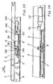
- the movable furniture part 103 to which this embodiment specifically refers is a door that swings with respect to the body of the piece of furniture, but it could also more generally be a drawer or similar parts. Moreover, as mentioned, the invention could also be applied to the field of general doors for houses or the like.
- the device 1 is preferably associated with a fixed guide 8 fastened to the static part 116 of the piece of furniture and having a supporting body 2 for a first slider 3 which moves reversibly in the direction of a sliding axis 100 between a rear end and a front end of a groove 4 in opposition to and through the action of first elastic means, in particular a first spring 5.
- the groove 4 extends rectilinearly in the direction of the sliding axis 100.
- the first slider 3 is engageable by first driving means present on a driving element 6 which moves reversibly in the direction of the sliding axis 100 between a position retracted in the fixed guide 8 and a position extracted from the fixed guide 8.
- the groove 4 comprises first means for movement of the first slider 3 transverse to the sliding axis 100 suitable to engage with specific guide means of the first slider 3.
- the groove 4 comprises second means for movement of the first slider 3 transverse to the sliding axis 100 suitable to engage with the guide means of the first slider 3.
- the first movement means comprise an intermediate side cavity 10 and a rear curve 11 of the groove 4.
- the second movement means comprise a front curve 14 of the groove 4 which extends from the same part of the groove 4 in which the intermediate side cavity 10 and the rear curve 11 are located.
- the guide means in turn comprise a front guide pin 12 and a rear guide pin 13.
- the front guide pin 12 and respectively the rear guide pin 13 are suitable to engage in the intermediate side cavity 10 and respectively in the rear curve 11 of the groove 4, and the front guide pin 12 is alternatively suitable to engage also in the front curve 14 of the groove 4.
- the first slider 3 comprises a rear surface slot 109 and a front surface slot 110 in which a driving pin 106 engages selectively.
- the rear slot 109 and the front slot 110 respectively have side walls 111 and 112 projecting with respect to the separation surface 113 between the front slot 109 and the rear slot 110 to intercept the driving pin 106.
- the separation surface 113 is flat and the side walls 111 and 112 project beyond the plane of the separation surface 113.
- the device 1 is also provided with an elastically yielding stop 9, fixed to the supporting body 2, against which the first slider 3 rests directly or indirectly before it engages with the guide means thereof in the first movement means of the groove 4.
- the stop 9, having a main axis oriented in the direction of the sliding axis 100, comprises a fixed part 9a and a movable part 9b between which a spring (not shown) is interposed, advantageously having greater elastic strength than that of the first spring 5 so that, when the first slider 3 is free to slide, it is capable of stopping it in the position corresponding to the closed position of the movable part 103.
- the device 1 also has means 104 for removable coupling between the movable part 103 and the driving element 6.
- the coupling means 104 can indistinctly comprise magnetic or mechanical connection means of known type, for example fitted to the internal side of the movable part 103 and to the front end of the driving element 6.
- the coupling force exerted by the coupling means must be calibrated so as to allow release thereof as a result of a reasonable force exerted by the user.
- the coupling means In the case of connection of mechanical type, the coupling means must allow separation of the elements in the extracted position of the driving element 6.
- a second slider 101 is also provided, carried by the fixed guide 8 and which moves reversibly in the direction of the sliding axis 100 in opposition to and through the action of second elastic means, in particular a second spring 102.
- the second slider 101 is engageable with second driving means 107 present on the driving element 6.
- the coupling force of the coupling means must be greater than the sum of the elastic return force towards the retracted position exerted indirectly on the driving element 6 by the first and second elastic means, and in particular by the first spring 5 and by the second spring 102.
- the driving element 6 has a rod-shaped main body 105 and is supported slidingly in a guide element 114 produced in a cover 115 of the fixed guide 8.
- the axis of the rod-shaped main body 105 extends in the direction of the sliding axis 100.
- the first driving means of the driving element 6 comprise a driving pin 106 which extends transversely to the rod-shaped main body 105 and is suitable to engage with the first slider 3.
- the second driving means of the driving element 6 comprise a tab 107 which extends laterally from the rod-shaped main body 105 and is constrained to slide in a guide slot 108 produced in the second slider 101.
- the device 1 has an ejector 20 supported in the fixed guide 8 behind the driving element 6.
- the ejector 20 which comprises a fixed part 20a containing a movable spindle 20b, is suitable to act against the rear base of the rod-shaped body 105 to generate an initial opening movement of the movable part 103 with a force greater than the force exerted thereon by any independent closing devices, such as those integrated in the hinges.
- the ejection force exerted by the ejector 20 is however less than the elastic force of the first spring 5.
- the ejector 20 is equipped in a known manner with a device for adjusting the pushing force exerted.
- the ejector 20 also has a main axis oriented in the direction of the sliding axis 100.
- Fig. 1 represents the situation of the device 1 when the movable part 103 is closed.
- the driving pin 106 engages in the rear slot 109 of the first slider 3 which is held in a first idle position in which it rests against the elastically yielding stop 9, the spring of which is not compressed, but only preloaded in order to hold the first slider 3 in position.
- the rear end of the driving element 6 rests against the head of the ejector 20 which has the spindle 20b in retracted position, as the force of the ejector 20 is less than the force of the first spring 5.
- the first slider 3 is made to move back into a second position by an external compression force (i.e. generated by the user) of the movable part 103.
- the driving pin 103 is released from the rear slot 109 and the driving element 6, as a result of the push exerted by the ejector 20 and now temporarily no longer opposed by the spring 5 or, naturally, by the user, is extracted to make the movable part 103 perform its initial opening movement which terminates when the driving pin 106 is intercepted by the projecting side wall 112 of the front slot 110 of the first slider 3.
- the tab 107 slides freely in its guide slot 108.
- the driving pin 106 intercepted by the side wall 112 of the front slot 110 of the first slider 3, firstly drives the first slider 3 causing the front 12 and respectively rear 13 guide pin to disengage from the intermediate side cavity 10 and respectively from the rear curve 11 of the groove 4. Movement of the first slider 3 transverse to the sliding axis 100 then causes the driving pin 106 to engage in the front slot 110.
- the tab 107 starts to drive the second slider 101 to the end of its travel in the position in which the front end of the second slider 101 is intercepted by the front wall of the fixed guide 8 and consequently further advance of the driving element 6 is blocked.
- the front guide pin 12 engages with the front curve 14 of the groove 4 making the first slider 3 move transversely to the direction of movement 100, as a result of which the driving pin 106 disengages from the front slot 110.
- the coupling force ensured by the coupling means is greater than the sum of the return force caused by the first spring 5 and the second spring 102, so that the driving element 6 can be driven forward.
- the driving element 6 When the driving element 6 reaches the end of its travel during extraction, in the case of magnetic connection the pulling force on the movable part 103 becomes predominant with respect to the coupling force ensured by the coupling means, or, in the case of mechanical connection, the coupling means are released from their coupling, the movable part 103 is released from the driving element 6 and can be taken to a position of complete opening.
- the second slider 101 retracts the driving element 6 towards the inside of the fixed guide 8.
- the driving pin 106 intercepted by the side wall 111 of the rear slot 109, initially causes the first slider 3 to move transversely to the sliding direction 100 and the front guide pin 12 to disengage from the front curve 14. Consequently, also the first slider 3 can be returned, through the spring 5, to the position thereof taken in the first step ( Fig. 6 ).
- this type of hinge makes the second slider and the second elastic means superfluous, and allows a decelerator to be provided optionally in place of the ejector to decelerate the closing movement of the swinging part caused by the spring 5 which moves the slider 3 back when it is coupled by the driving element 6.
- the device therefore allows simple and functional opening and closing of a door or drawer facilitating grasping thereof by the user and providing guided closing thereof.
- a self-closing device for a movable furniture part is a drawer, but it could also more generally be a door that swings with respect to the body of the piece of furniture or similar parts.
- the invention could also be applied to the field of general doors for houses or the like.
- the device 1 comprises, associated with a fixed guide 8, a supporting body 2 for a slider 3 which moves reversibly along a sliding axis 100 in opposition to and through the action of first elastic means, in particular a first spring 5 coupled at one end thereof with a connection 150 produced on an extension of the slider 3 and at the other end thereof with a connection 151 produced on an extension of the supporting body 2.
- first elastic means in particular a first spring 5 coupled at one end thereof with a connection 150 produced on an extension of the slider 3 and at the other end thereof with a connection 151 produced on an extension of the supporting body 2.
- the slider 3 is engageable with driving means present on a driving element 6 which moves reversibly in the direction of the sliding axis 100 integral with an extractable guide 7 of the drawer to which it is fixed.
- the supporting body 2 comprises first means for movement of the slider 3 suitable to engage with specific guide means of the slider so as to release it from the driving means.
- An elastically yielding stop 9 is also present, against which the slider 3 rests directly or indirectly before it engages with the guide means in the first movement means.
- the stop 9, having a main axis oriented in the direction of the sliding axis 100, comprises a fixed part 9a and a movable part 9b between which a spring (not shown) is interposed, advantageously having greater elastic strength than that of the first spring 5 so that, when the first slider 3 is free to slide, it is capable of stopping it in the position corresponding to the closed position of the movable part 103.
- the coupling means comprise a driving pin 106 which extends transversely to the sliding axis 100 and is suitable to engage with the slider 3.
- the supporting body 2 has a groove 4 which in the area of the rear end thereof comprises the first means for movement of the slider 3 and in the area of the front end thereof comprises second means for movement of the slider 3 transverse to the sliding axis 100 suitable to engage with the guide means of the slider 3.
- the groove extends rectilinearly in the direction of the sliding axis 100.
- the first movement means comprise an intermediate side cavity 10 and a rear curve 11 of the groove 4.
- the second movement means instead comprise a front curve 14 of the groove 4 which extends from the same part of the groove 4 in which the intermediate side cavity 10 and the rear curve 11 are located.
- the guide means in turn comprise a front guide pin 12 and a rear guide pin 13.
- the front guide pin 12 and respectively the rear guide pin 13 are suitable to engage in the intermediate side cavity 10 and respectively in the rear curve 11 of the groove 4, and the front guide pin 12 is alternatively suitable to engage also in the front curve 14 of the groove 4.
- the first slider 3 comprises a rear surface slot 109 and a front surface slot 110 in which the driving pin 106 engages selectively.
- the rear slot 109 and the front slot 110 respectively have side walls 111 and 112 projecting with respect to the separation surface 113 between the front slot 109 and the rear slot 110 to intercept the driving pin 106.
- the separation surface 113 is flat and the side walls 111 and 112 project beyond the plane of the separation surface 113.
- An ejector 20, suitable to move the drawer for initial opening thereof, can be associated with the device.
- the ejector 20 is suitable to interact with a stop 21 integral with the extractable guide 7, but its force is lower than the force exerted by the first spring 5.
- the ejector 20 which comprises a fixed part 20a containing a movable spindle 20b, is provided in a known manner with a device to regulate the pushing force exerted, and also has a main axis oriented in the direction of the sliding axis 100.
- the ejector can be replaced by an adequate inclination, not shown, of the fixed and/or sliding guides of the drawer, along which it can slide through gravity.
- the ejector can be replaced by magnets, not shown here, oriented to generate repulsion forces, capable of allowing the drawer to slide and facilitating, as in the other cases, grasping thereof by the user.
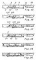
- Fig. 15 represents the situation of the device 1 when the drawer is closed.
- the driving pin 106 engages in the rear slot 109 of the slider 3 which is held in a first idle position in which it rests against the elastically yielding stop 9, the spring of which is not compressed, but only preloaded in order to hold the slider 3 in position.
- the stop 21 rests against the head of the ejector 20 which has the spindle 20b in retracted position, as the force of the ejector 20 is less than the force of the first spring 5.
- the slider 3 is made to move back by an external compression force (i.e. generated by the user) applied to the drawer.
- an external compression force i.e. generated by the user
- the front guide pin 12 and respectively the rear guide pin 13 engage in the intermediate side cavity 10 and respectively in the rear curve 11 of the groove 4.
- Movement of the slider 3 transverse to the sliding axis 100 causes the driving pin 106 to disengage from the rear slot 109.
- the driving pin 103 is released from the rear slot 109 and, as a result of the push exerted by the ejector 20 and now temporarily no longer opposed by the spring 5 or, naturally, by the user, it moves to make the drawer perform its initial opening movement which terminates when the driving pin 106 is intercepted by the projecting side wall 112 of the front slot 110 of the slider 3.
- the driving pin 106 intercepted by the side wall 112 of the front slot 110 of the slider 3, firstly drives the slider 3 causing the front 12 and respectively rear 13 guide pin to disengage from the intermediate side cavity 10 and respectively from the rear curve 11 of the groove 4. Movement of the slider 3 transverse to the sliding axis 100 then causes the driving pin 106 to engage in the front slot 110.
- the front guide pin 12 engages with the front curve 14 of the groove 4 making the slider 3 move transversely to the direction of movement 100, as a result of which the driving pin 106 disengages from the front slot 110 and proceeds freely to the position of complete opening of the drawer.
- the drawer is pushed closed by the user.
- the driving pin 106 intercepted by the side wall 111 of the rear slot 109, initially causes the slider 3 to move transversely to the sliding direction 100 and the front guide pin 12 to disengage from the front curve 14. Consequently, the slider 3 can be returned, through the spring 5, to the position thereof taken in the first step ( Fig. 15 ).
- the ejector can be housed on the supporting body 2 behind the elastically yielding element.
- inclined guides can take the place of the ejectors, rather than magnets or other systems suitable to move the drawer.
- the elastically yielding stop 9 is replaced by a mechanical stop formed by a step 120 of the supporting body 2 arranged transversely to the direction of the slider 3.
- the slider 3 rests with a rear wall 119 thereof against the step 120.
- the pin 106 integral with the extractable guide 7 is pushed against an inclined surface 118 of the slider 3, which causes lateral movement thereof along the step 120 and inside the appropriate side slots 10, 11 of the groove 4, so that the pin 106 is released and the extractable guide 7 can be pushed to open by the ejector 20a, 20b.
- the device according to the invention is particularly advantageous to allow simple and functional opening and closing of a drawer facilitating grasping thereof by the user and providing guided closing thereof.
- the materials used and the sizes can be any according to requirements and to the state of the art.
Claims (18)
- Dispositif de fermeture automatique (1) destiné particulièrement à une partie de meuble mobile (103) combinable avec un système d'ouverture de celle-ci; comprenant un guide fixe (8) comportant un corps de support (2) dans lequel un premier coulisseau (3) pouvant coulisser de façon réversible le long d'un axe de coulissement (100) en opposition à et sous l'action de premiers moyens élastiques (5), ledit premier coulisseau (3) pouvant venir en prise avec des premiers moyens d'entraînement comprenant une cheville d'entraînement (106) présente sur un élément d'entraînement (6) qui coulisse de façon réversible dans la direction dudit axe de coulissement (100), ledit corps de support (2) comprenant des premiers moyens assurant le mouvement dudit premier coulisseau (3) pouvant venir en prise avec les moyens de guidage dudit premier coulisseau (3), de sorte à le relâcher desdits moyens d'entraînement, et aussi pourvu d'un arrêt mécanique ou pouvant céder de façon élastique (9, 120) contre lequel ledit premier coulisseau (3) repose directement ou indirectement avant qu'il ne s'engage avec lesdits moyens de guidage dans lesdits premiers moyens de déplacement, ledit corps de support (2) comportant une rainure (4) qui, dans la zone de l'extrémité arrière comprend lesdits premiers moyens de déplacement dudit premier coulisseau (3) et dans la zone de l'extrémité avant comprend des seconds moyens de déplacement dudit premier coulisseau (3) transversaux au dit axe de coulissement (100) pouvant venir en prise avec lesdits moyens de guidage dudit premier coulisseau (3) caractérisé en ce que ledit premier coulisseau (3) comprend une encoche arrière (109) et une encoche avant (110) dans lesquelles ladite cheville d'entraînement (106) s'engage de manière sélective, ladite encoche avant (110) et ladite encoche arrière (109) comportant respectivement une cloison latérale (112, 111) en saillie par rapport à la surface (113) séparant ladite encoche avant (110) et ladite encoche arrière (109) afin d'intercepter ladite cheville d'entraînement (106).
- Dispositif de fermeture automatique (1) selon la revendication 1, caractérisé en ce que lesdits premiers moyens de déplacement comprennent une cavité latérale intermédiaire (10) et un arrondi arrière (11) de ladite rainure (4).
- Dispositif de fermeture automatique (1) selon la revendication 1 ou 2 caractérisé en ce que lesdits seconds moyens de déplacement comprennent un arrondi avant (14) de ladite rainure (4) disposé sur la même partie de ladite rainure (4) dans laquelle ladite cavité latérale intermédiaire (10) et ledit arrondi arrière (11) sont situés.
- Dispositif de fermeture automatique (1) selon l'une ou plusieurs des revendications précédentes, caractérisé en ce que lesdits moyens de guidage comprennent un goujon de guidage avant (12) et un goujon de guidage arrière (13), ledit goujon de guidage avant (12) et ledit goujon de guidage arrière (13) pouvant s'engager dans ladite cavité latérale intermédiaire (10) et dans ledit arrondi arrière (11) de ladite rainure (4), ledit goujon de guidage avant (12) pouvant aussi s'engager alternativement dans ledit arrondi avant (14).
- Dispositif de fermeture automatique (1) selon l'une ou plusieurs des revendications précédentes, caractérisé en ce que ledit élément d'entraînement (6) est supporté en coulissant dans un élément de guidage (114) réalisé dans une enveloppe (115) dudit guide fixe (8).
- Dispositif de fermeture automatique (1) selon l'une ou plusieurs des revendications précédentes, caractérisé en ce qu'il possède des moyens d'accouplement amovibles (104) entre ledit élément mobile (103) et ledit élément d'entraînement (6).
- Dispositif de fermeture automatique (1) selon l'une ou plusieurs des revendications précédentes, caractérisé en ce qu'il comprend un second coulisseau (101) porté par ledit guide fixe (8) et coulissant de façon réversible dans la direction dudit axe de coulissement (100), en opposition à et sous l'action de seconds moyens élastiques (102), ledit second coulisseau (101) pouvant venir en prise avec des seconds moyens d'entraînement (107) disposés sur ledit élément d'entraînement (6).
- Dispositif de fermeture automatique (1) selon les revendications 6 ou 7, caractérisé en ce que lesdits moyens d'accouplement mobiles (104) possèdent une force d'accouplement supérieure à la somme de la force de contre-pression élastique exercée indirectement sur ledit élément d'entraînement (6) par lesdits premier (5) et second (102) moyens élastiques.
- Dispositif de fermeture automatique (1) selon la revendication 7, caractérisé en ce que lesdits seconds moyens d'entraînement comprennent une languette (107) se développant transversalement à partir de l'élément d'entraînement (6) et forcée de coulisser dans une encoche de guidage (108) réalisée dans ledit second coulisseau (101).
- Dispositif de fermeture automatique (1) selon l'une ou plusieurs des revendications précédentes, caractérisé en ce que ledit guide fixe (8) supporte, derrière ledit élément d'entraînement (6), un éjecteur (20) apte à générer un mouvement d'ouverture initial de ladite partie mobile (103).
- Dispositif de fermeture automatique (1) selon l'une ou plusieurs des revendications précédentes, caractérisé en ce que ledit éjecteur (20) comporte une force d'éjection inférieure à la force élastique desdits premiers moyens élastiques (5).
- Dispositif de fermeture automatique (1) selon l'une ou plusieurs des revendications de 1 à 6, caractérisé en ce que ledit guide fixe (2) supporte, derrière ledit élément d'entraînement (6), un ralentisseur apte à agir contre la base arrière dudit élément d'entraînement (6) pour ralentir la fermeture de ladite partie mobile (103).
- Dispositif de fermeture automatique (1) selon l'une ou plusieurs des revendications précédentes, caractérisé en ce que ledit élément d'entraînement (6) peut coulisser de façon réversible dans la direction dudit axe de coulissement (100) solidaire d'un guide extractible (7).
- Dispositif de fermeture automatique (1) selon l'une ou plusieurs des revendications précédentes, caractérisé en ce que lesdits premiers moyens élastiques (5) exercent sur ledit coulisseau (3) en contact avec ledit premier arrêt pouvant céder de façon élastique (9) une force élastique inférieure à la force élastique générée par ledit premier arrêt pouvant céder de façon élastique (9).
- Dispositif de fermeture automatique (1) selon l'une ou plusieurs des revendications précédentes, caractérisé en ce que ledit arrêt mécanique est formé par un redan (120) dudit corps de support (2) disposé transversalement par rapport à la direction dudit premier coulisseau (3) qui, à son tour, repose avec une cloison arrière (119) contre ledit redan (120).
- Dispositif de fermeture automatique (1) selon la revendication précédente, caractérisé en ce que ledit premier coulisseau (3) possède une surface inclinée (118) contre laquelle la cheville d'entraînement (106) est apte à être poussée de sorte à déplacer latéralement ledit premier coulisseau (3) le long dudit redan (120).
- Pièce de meuble pourvue d'un dispositif (1) selon l'une ou plusieurs des revendications précédentes et comportant des charnières avec un dispositif permettant de pousser la partie du meuble mobile dans la direction de fermeture.
- Pièce de meuble pourvue d'un dispositif (1) selon l'une ou plusieurs des revendications précédentes et comportant des charnières avec un dispositif permettant de pousser la partie du meuble mobile dans la direction d'ouverture.
Priority Applications (2)
| Application Number | Priority Date | Filing Date | Title |
|---|---|---|---|
| PL09778743T PL2315898T3 (pl) | 2008-10-13 | 2009-09-28 | Urządzenie samozamykające i otwierające w szczególności dla ruchomej części mebla |
| SI200930494T SI2315898T1 (sl) | 2008-10-13 | 2009-09-28 | Samozapiralna in samoodpiralna naprava, zlasti za premični pohištveni del |
Applications Claiming Priority (3)
| Application Number | Priority Date | Filing Date | Title |
|---|---|---|---|
| ITMI2008A001812A IT1392328B1 (it) | 2008-10-13 | 2008-10-13 | Dispositivo di autochiusura di una parte spostabile di un mobile |
| ITMI2008A001849A IT1392653B1 (it) | 2008-10-17 | 2008-10-17 | Dispositivo di auto chiusura di una parte spostabile di un mobile |
| PCT/EP2009/006970 WO2010043306A1 (fr) | 2008-10-13 | 2009-09-28 | Dispositif d’ouverture et de fermeture automatique, en particulier pour un élément mobile d’un meuble |
Publications (2)
| Publication Number | Publication Date |
|---|---|
| EP2315898A1 EP2315898A1 (fr) | 2011-05-04 |
| EP2315898B1 true EP2315898B1 (fr) | 2012-11-07 |
Family
ID=41334539
Family Applications (1)
| Application Number | Title | Priority Date | Filing Date |
|---|---|---|---|
| EP09778743A Active EP2315898B1 (fr) | 2008-10-13 | 2009-09-28 | Dispositif d'ouverture et de fermeture automatique, en particulier pour un élément mobile d'un meuble |
Country Status (12)
| Country | Link |
|---|---|
| US (1) | US8668288B2 (fr) |
| EP (1) | EP2315898B1 (fr) |
| JP (1) | JP5624547B2 (fr) |
| KR (1) | KR20110083625A (fr) |
| CN (1) | CN102203367B (fr) |
| BR (1) | BRPI0914011A2 (fr) |
| ES (1) | ES2397814T3 (fr) |
| HK (1) | HK1158721A1 (fr) |
| PL (1) | PL2315898T3 (fr) |
| SI (1) | SI2315898T1 (fr) |
| TW (1) | TWI437967B (fr) |
| WO (1) | WO2010043306A1 (fr) |
Families Citing this family (25)
| Publication number | Priority date | Publication date | Assignee | Title |
|---|---|---|---|---|
| IT1392907B1 (it) * | 2008-09-12 | 2012-04-02 | Salice Arturo Spa | Dispositivo di auto chiusura di un cassetto o di una parte spostabile di un mobile |
| IT1392184B1 (it) * | 2008-12-12 | 2012-02-22 | Salice Arturo Spa | Dispositivo di apertura e chiusura di una parte spostabile di un mobile |
| DE102008061728A1 (de) * | 2008-12-12 | 2010-06-17 | Dorma Gmbh + Co. Kg | Schiebetür |
| JP5433466B2 (ja) * | 2010-03-17 | 2014-03-05 | 株式会社ニフコ | 摺動補助装置 |
| JP2011196015A (ja) * | 2010-03-17 | 2011-10-06 | Nifco Inc | 摺動補助装置 |
| AT509934B1 (de) | 2010-05-20 | 2016-01-15 | Blum Gmbh Julius | Antriebsvorrichtung zum bewegen eines bewegbaren möbelteils |
| DE202010013193U1 (de) * | 2010-12-22 | 2012-03-26 | Paul Hettich Gmbh & Co. Kg | Öffnungs- und Schließvorrichtung für bewegbare Möbelteile und Ausstoßvorrichtung |
| DE102011122266A1 (de) | 2011-12-23 | 2013-06-27 | Grass Gmbh | Vorrichtung zur Bewegungsbeeinflussung eines Möbelteils, Führungseinheit zur Bewegungsführung eines Möbelteils und Möbel |
| AT511938B1 (de) * | 2012-01-18 | 2013-04-15 | Blum Gmbh Julius | Antriebsvorrichtung für ein bewegbares möbelteil |
| AT512509B1 (de) * | 2012-07-10 | 2013-09-15 | Blum Gmbh Julius | Ausstoßvorrichtung für ein bewegbares Möbelteil |
| ITMI20121718A1 (it) * | 2012-10-12 | 2014-04-13 | Salice Arturo Spa | Mobile con almeno un cassetto o simile |
| ES2474290B1 (es) * | 2013-01-08 | 2015-01-02 | Industrias Auxiliares, S.A. (Indaux) | Dispositivo de autocierre para partes móviles correderas |
| AT514143A1 (de) * | 2013-04-12 | 2014-10-15 | Blum Gmbh Julius | Antriebsvorrichtung für ein bewegbares Möbelteil |
| DE102013103989A1 (de) * | 2013-04-19 | 2014-11-06 | Hettich-Heinze Gmbh & Co. Kg | Führungsvorrichtung |
| TWI536933B (zh) | 2015-11-12 | 2016-06-11 | 川湖科技股份有限公司 | 滑軌總成 |
| TWI532452B (zh) | 2015-11-12 | 2016-05-11 | 川湖科技股份有限公司 | 驅動機構 |
| TWI538638B (zh) | 2015-11-12 | 2016-06-21 | 川湖科技股份有限公司 | 用於傢俱組件的驅動機構及方法 |
| TWI572304B (zh) | 2016-03-31 | 2017-03-01 | 川湖科技股份有限公司 | 用於傢俱組件的驅動機構及方法 |
| CN107296407B (zh) * | 2016-04-13 | 2019-03-15 | 川湖科技股份有限公司 | 家具组件及其驱动机构、方法 |
| DE102016120593A1 (de) * | 2016-10-27 | 2018-05-03 | Hettich-Oni Gmbh & Co. Kg | Öffnungs- und Schließsystem mit einer Ausstoßvorrichtung für ein Möbel und Betriebsverfahren für ein Öffnungs- und Schließsystem |
| CN106361025B (zh) * | 2016-11-11 | 2018-12-28 | 伍志勇 | 一种家具用弹射器结构 |
| KR102470209B1 (ko) * | 2018-04-27 | 2022-11-22 | 엘지전자 주식회사 | 드로워 가이드 및 드로워 가이드가 구비된 의류처리장치 |
| DE202019005925U1 (de) * | 2018-06-13 | 2023-06-27 | Wolfgang Held | Vorrichtung zum Öffnen und Schließen von gelagerten Abdeckungen |
| IT201800011081A1 (it) * | 2018-12-13 | 2020-06-13 | Car S R L | Dispositivo di apertura per un'anta o un cassetto e mobile comprendente detto dispositivo |
| US10677512B1 (en) * | 2019-01-31 | 2020-06-09 | Whirlpool Corporation | Appliance push-to-open system and method of installing the push-to-open system |
Citations (1)
| Publication number | Priority date | Publication date | Assignee | Title |
|---|---|---|---|---|
| WO2010028722A2 (fr) * | 2008-09-12 | 2010-03-18 | Arturo Salice S.P.A. | Dispositif de fermeture automatique de tiroir ou de partie mobile d'un meuble |
Family Cites Families (19)
| Publication number | Priority date | Publication date | Assignee | Title |
|---|---|---|---|---|
| US3854785A (en) * | 1972-09-16 | 1974-12-17 | Krause Kg Robert | Actuating device |
| AT401717B (de) * | 1993-06-23 | 1996-11-25 | Blum Gmbh Julius | Schliessvorrichtung für schubladen |
| JP2550377Y2 (ja) * | 1993-09-14 | 1997-10-08 | 磯川産業株式会社 | マグネットブッシュラッチ |
| IT250443Y1 (it) * | 2000-09-19 | 2003-09-10 | Salice Arturo Spa | Dispositivo per la chiusura decelerata di parti di mobile scorrevoli |
| JP3996584B2 (ja) * | 2003-03-31 | 2007-10-24 | Thk株式会社 | 引込み装置、引出し装置及び引き戸装置 |
| MY140924A (en) * | 2003-05-22 | 2010-02-12 | Harn Marketing Sdn Bhd | A drawer stabilizing arrangement for double walled drawer |
| DE20311795U1 (de) * | 2003-07-31 | 2004-11-18 | Alfit Ag | Schubladen-Ausziehführung mit Einzugsautomatik mit integrierter Dämpfung |
| ITMC20030144A1 (it) * | 2003-12-05 | 2005-06-06 | Compagnucci Spa Ora Compagnucci Ho Lding Spa | Dispositivo per la chiusura automatica ed ammortizzata dei cassetti e delle strutture estraibili per mobili. |
| AT503066B1 (de) | 2004-12-03 | 2008-01-15 | Blum Gmbh Julius | Antriebsvorrichtung für ein bewegbar gelagertes möbelteil |
| DE202005009860U1 (de) * | 2004-12-17 | 2006-04-20 | Alfit Ag | Schließ- und Öffnungsvorrichtung für Schubladen |
| AT501778B1 (de) * | 2005-04-28 | 2009-11-15 | Blum Gmbh Julius | Ausstossvorrichtung für ein bewegbares möbelteil |
| AT502939A1 (de) * | 2005-04-28 | 2007-06-15 | Blum Gmbh Julius | Möbel |
| DE202006020236U1 (de) * | 2005-11-10 | 2008-02-07 | Grass Gmbh | Vorrichtung zum Öffnen und Schließen eines bewegbaren Möbelteils und Möbelteil |
| JP4806609B2 (ja) * | 2005-11-21 | 2011-11-02 | トックベアリング株式会社 | 引き込みユニット |
| DE102006058639B4 (de) * | 2006-12-11 | 2008-08-14 | Zimmer, Günther | Kombinierte Verzögerungs- und Beschleunigungsvorrichtung |
| CN201182372Y (zh) * | 2008-03-13 | 2009-01-21 | 佛山市顺德区泰明金属制品厂有限公司 | 抽屉滑轨闭合装置 |
| DE102008021458A1 (de) * | 2008-04-29 | 2010-01-07 | Zimmer, Günther | Beschleunigungsvorrichtung mit zwei Energiespeichern |
| IT1392184B1 (it) * | 2008-12-12 | 2012-02-22 | Salice Arturo Spa | Dispositivo di apertura e chiusura di una parte spostabile di un mobile |
| US8240788B2 (en) * | 2010-03-04 | 2012-08-14 | Sun Chain Metal Industry Co., Ltd. | Hidden self-closing drawer slide assembly |
-
2009
- 2009-09-28 ES ES09778743T patent/ES2397814T3/es active Active
- 2009-09-28 CN CN200980140646.7A patent/CN102203367B/zh active Active
- 2009-09-28 PL PL09778743T patent/PL2315898T3/pl unknown
- 2009-09-28 US US13/120,573 patent/US8668288B2/en not_active Expired - Fee Related
- 2009-09-28 SI SI200930494T patent/SI2315898T1/sl unknown
- 2009-09-28 KR KR1020117008380A patent/KR20110083625A/ko not_active Application Discontinuation
- 2009-09-28 EP EP09778743A patent/EP2315898B1/fr active Active
- 2009-09-28 WO PCT/EP2009/006970 patent/WO2010043306A1/fr active Application Filing
- 2009-09-28 JP JP2011530394A patent/JP5624547B2/ja active Active
- 2009-09-28 BR BRPI0914011A patent/BRPI0914011A2/pt not_active IP Right Cessation
- 2009-10-08 TW TW098134117A patent/TWI437967B/zh active
-
2011
- 2011-12-08 HK HK11113291.6A patent/HK1158721A1/xx unknown
Patent Citations (1)
| Publication number | Priority date | Publication date | Assignee | Title |
|---|---|---|---|---|
| WO2010028722A2 (fr) * | 2008-09-12 | 2010-03-18 | Arturo Salice S.P.A. | Dispositif de fermeture automatique de tiroir ou de partie mobile d'un meuble |
Also Published As
| Publication number | Publication date |
|---|---|
| WO2010043306A1 (fr) | 2010-04-22 |
| KR20110083625A (ko) | 2011-07-20 |
| SI2315898T1 (sl) | 2013-04-30 |
| ES2397814T3 (es) | 2013-03-11 |
| EP2315898A1 (fr) | 2011-05-04 |
| JP5624547B2 (ja) | 2014-11-12 |
| TWI437967B (zh) | 2014-05-21 |
| JP2012505326A (ja) | 2012-03-01 |
| HK1158721A1 (en) | 2012-07-20 |
| BRPI0914011A2 (pt) | 2019-09-24 |
| US8668288B2 (en) | 2014-03-11 |
| CN102203367B (zh) | 2014-09-17 |
| PL2315898T3 (pl) | 2013-03-29 |
| US20110254416A1 (en) | 2011-10-20 |
| CN102203367A (zh) | 2011-09-28 |
| TW201029603A (en) | 2010-08-16 |
Similar Documents
| Publication | Publication Date | Title |
|---|---|---|
| EP2315898B1 (fr) | Dispositif d'ouverture et de fermeture automatique, en particulier pour un élément mobile d'un meuble | |
| EP2262397B1 (fr) | Dispositif pour ouvrir et fermer la partie mobile d'une unité de mobilier | |
| EP2320767B1 (fr) | Dispositif de fermeture automatique de tiroir ou de partie mobile d'un meuble | |
| CN104135894B (zh) | 用于可动的家具部件的驱动装置 | |
| US8256853B2 (en) | Opening device for a slide assembly | |
| CN101605479B (zh) | 活动家具部件的推出器 | |
| US7331643B2 (en) | Piece of furniture with a movable furniture component | |
| EP2532272A1 (fr) | Mécanisme d'ouverture d'un ensemble coulissant | |
| EP2371241B1 (fr) | Ensemble de rails de tiroir avec dispositif d'ouverture | |
| EP2304153B1 (fr) | Système de déplacement de panneau | |
| JP6236235B2 (ja) | 貯蔵庫の扉開閉構造 | |
| ES2832658T3 (es) | Dispositivo de accionamiento para una parte de mueble móvil y método para abrir y cerrar una parte de mueble móvil | |
| KR20180036511A (ko) | 개폐 장치 | |
| CN103082701A (zh) | 用于可运动的家具橱柜部件的自动闭合系统 | |
| CN109922694B (zh) | 家具和用于打开抽屉和内抽屉的方法 | |
| ES2937730T3 (es) | Dispositivo de accionamiento para una pieza de mueble móvil |
Legal Events
| Date | Code | Title | Description |
|---|---|---|---|
| PUAI | Public reference made under article 153(3) epc to a published international application that has entered the european phase |
Free format text: ORIGINAL CODE: 0009012 |
|
| 17P | Request for examination filed |
Effective date: 20110308 |
|
| AK | Designated contracting states |
Kind code of ref document: A1 Designated state(s): AT BE BG CH CY CZ DE DK EE ES FI FR GB GR HR HU IE IS IT LI LT LU LV MC MK MT NL NO PL PT RO SE SI SK SM TR |
|
| AX | Request for extension of the european patent |
Extension state: AL BA RS |
|
| 17Q | First examination report despatched |
Effective date: 20110930 |
|
| DAX | Request for extension of the european patent (deleted) | ||
| GRAP | Despatch of communication of intention to grant a patent |
Free format text: ORIGINAL CODE: EPIDOSNIGR1 |
|
| GRAC | Information related to communication of intention to grant a patent modified |
Free format text: ORIGINAL CODE: EPIDOSCIGR1 |
|
| GRAS | Grant fee paid |
Free format text: ORIGINAL CODE: EPIDOSNIGR3 |
|
| GRAA | (expected) grant |
Free format text: ORIGINAL CODE: 0009210 |
|
| AK | Designated contracting states |
Kind code of ref document: B1 Designated state(s): AT BE BG CH CY CZ DE DK EE ES FI FR GB GR HR HU IE IS IT LI LT LU LV MC MK MT NL NO PL PT RO SE SI SK SM TR |
|
| REG | Reference to a national code |
Ref country code: GB Ref legal event code: FG4D |
|
| REG | Reference to a national code |
Ref country code: AT Ref legal event code: REF Ref document number: 583094 Country of ref document: AT Kind code of ref document: T Effective date: 20121115 Ref country code: CH Ref legal event code: EP |
|
| REG | Reference to a national code |
Ref country code: IE Ref legal event code: FG4D |
|
| REG | Reference to a national code |
Ref country code: DE Ref legal event code: R096 Ref document number: 602009011065 Country of ref document: DE Effective date: 20130103 |
|
| REG | Reference to a national code |
Ref country code: ES Ref legal event code: FG2A Ref document number: 2397814 Country of ref document: ES Kind code of ref document: T3 Effective date: 20130311 |
|
| REG | Reference to a national code |
Ref country code: PL Ref legal event code: T3 |
|
| REG | Reference to a national code |
Ref country code: NL Ref legal event code: VDEP Effective date: 20121107 |
|
| REG | Reference to a national code |
Ref country code: LT Ref legal event code: MG4D |
|
| PG25 | Lapsed in a contracting state [announced via postgrant information from national office to epo] |
Ref country code: NO Free format text: LAPSE BECAUSE OF FAILURE TO SUBMIT A TRANSLATION OF THE DESCRIPTION OR TO PAY THE FEE WITHIN THE PRESCRIBED TIME-LIMIT Effective date: 20130207 Ref country code: HR Free format text: LAPSE BECAUSE OF FAILURE TO SUBMIT A TRANSLATION OF THE DESCRIPTION OR TO PAY THE FEE WITHIN THE PRESCRIBED TIME-LIMIT Effective date: 20121107 Ref country code: SE Free format text: LAPSE BECAUSE OF FAILURE TO SUBMIT A TRANSLATION OF THE DESCRIPTION OR TO PAY THE FEE WITHIN THE PRESCRIBED TIME-LIMIT Effective date: 20121107 Ref country code: FI Free format text: LAPSE BECAUSE OF FAILURE TO SUBMIT A TRANSLATION OF THE DESCRIPTION OR TO PAY THE FEE WITHIN THE PRESCRIBED TIME-LIMIT Effective date: 20121107 Ref country code: NL Free format text: LAPSE BECAUSE OF FAILURE TO SUBMIT A TRANSLATION OF THE DESCRIPTION OR TO PAY THE FEE WITHIN THE PRESCRIBED TIME-LIMIT Effective date: 20121107 Ref country code: LT Free format text: LAPSE BECAUSE OF FAILURE TO SUBMIT A TRANSLATION OF THE DESCRIPTION OR TO PAY THE FEE WITHIN THE PRESCRIBED TIME-LIMIT Effective date: 20121107 Ref country code: IS Free format text: LAPSE BECAUSE OF FAILURE TO SUBMIT A TRANSLATION OF THE DESCRIPTION OR TO PAY THE FEE WITHIN THE PRESCRIBED TIME-LIMIT Effective date: 20130307 |
|
| PG25 | Lapsed in a contracting state [announced via postgrant information from national office to epo] |
Ref country code: PT Free format text: LAPSE BECAUSE OF FAILURE TO SUBMIT A TRANSLATION OF THE DESCRIPTION OR TO PAY THE FEE WITHIN THE PRESCRIBED TIME-LIMIT Effective date: 20130307 Ref country code: GR Free format text: LAPSE BECAUSE OF FAILURE TO SUBMIT A TRANSLATION OF THE DESCRIPTION OR TO PAY THE FEE WITHIN THE PRESCRIBED TIME-LIMIT Effective date: 20130208 Ref country code: BE Free format text: LAPSE BECAUSE OF FAILURE TO SUBMIT A TRANSLATION OF THE DESCRIPTION OR TO PAY THE FEE WITHIN THE PRESCRIBED TIME-LIMIT Effective date: 20121107 Ref country code: LV Free format text: LAPSE BECAUSE OF FAILURE TO SUBMIT A TRANSLATION OF THE DESCRIPTION OR TO PAY THE FEE WITHIN THE PRESCRIBED TIME-LIMIT Effective date: 20121107 |
|
| REG | Reference to a national code |
Ref country code: HU Ref legal event code: AG4A Ref document number: E015743 Country of ref document: HU |
|
| PG25 | Lapsed in a contracting state [announced via postgrant information from national office to epo] |
Ref country code: EE Free format text: LAPSE BECAUSE OF FAILURE TO SUBMIT A TRANSLATION OF THE DESCRIPTION OR TO PAY THE FEE WITHIN THE PRESCRIBED TIME-LIMIT Effective date: 20121107 Ref country code: SK Free format text: LAPSE BECAUSE OF FAILURE TO SUBMIT A TRANSLATION OF THE DESCRIPTION OR TO PAY THE FEE WITHIN THE PRESCRIBED TIME-LIMIT Effective date: 20121107 Ref country code: BG Free format text: LAPSE BECAUSE OF FAILURE TO SUBMIT A TRANSLATION OF THE DESCRIPTION OR TO PAY THE FEE WITHIN THE PRESCRIBED TIME-LIMIT Effective date: 20130207 Ref country code: DK Free format text: LAPSE BECAUSE OF FAILURE TO SUBMIT A TRANSLATION OF THE DESCRIPTION OR TO PAY THE FEE WITHIN THE PRESCRIBED TIME-LIMIT Effective date: 20121107 |
|
| PG25 | Lapsed in a contracting state [announced via postgrant information from national office to epo] |
Ref country code: RO Free format text: LAPSE BECAUSE OF FAILURE TO SUBMIT A TRANSLATION OF THE DESCRIPTION OR TO PAY THE FEE WITHIN THE PRESCRIBED TIME-LIMIT Effective date: 20121107 |
|
| PLBE | No opposition filed within time limit |
Free format text: ORIGINAL CODE: 0009261 |
|
| STAA | Information on the status of an ep patent application or granted ep patent |
Free format text: STATUS: NO OPPOSITION FILED WITHIN TIME LIMIT |
|
| 26N | No opposition filed |
Effective date: 20130808 |
|
| PGFP | Annual fee paid to national office [announced via postgrant information from national office to epo] |
Ref country code: SI Payment date: 20130906 Year of fee payment: 5 Ref country code: HU Payment date: 20130910 Year of fee payment: 5 Ref country code: CZ Payment date: 20130918 Year of fee payment: 5 |
|
| PG25 | Lapsed in a contracting state [announced via postgrant information from national office to epo] |
Ref country code: CY Free format text: LAPSE BECAUSE OF FAILURE TO SUBMIT A TRANSLATION OF THE DESCRIPTION OR TO PAY THE FEE WITHIN THE PRESCRIBED TIME-LIMIT Effective date: 20121107 |
|
| PGFP | Annual fee paid to national office [announced via postgrant information from national office to epo] |
Ref country code: PL Payment date: 20130903 Year of fee payment: 5 |
|
| REG | Reference to a national code |
Ref country code: DE Ref legal event code: R097 Ref document number: 602009011065 Country of ref document: DE Effective date: 20130808 |
|
| PG25 | Lapsed in a contracting state [announced via postgrant information from national office to epo] |
Ref country code: MC Free format text: LAPSE BECAUSE OF FAILURE TO SUBMIT A TRANSLATION OF THE DESCRIPTION OR TO PAY THE FEE WITHIN THE PRESCRIBED TIME-LIMIT Effective date: 20121107 |
|
| REG | Reference to a national code |
Ref country code: CH Ref legal event code: PL |
|
| GBPC | Gb: european patent ceased through non-payment of renewal fee |
Effective date: 20130928 |
|
| REG | Reference to a national code |
Ref country code: FR Ref legal event code: ST Effective date: 20140530 |
|
| REG | Reference to a national code |
Ref country code: IE Ref legal event code: MM4A |
|
| PG25 | Lapsed in a contracting state [announced via postgrant information from national office to epo] |
Ref country code: CH Free format text: LAPSE BECAUSE OF NON-PAYMENT OF DUE FEES Effective date: 20130930 Ref country code: LI Free format text: LAPSE BECAUSE OF NON-PAYMENT OF DUE FEES Effective date: 20130930 Ref country code: GB Free format text: LAPSE BECAUSE OF NON-PAYMENT OF DUE FEES Effective date: 20130928 Ref country code: IE Free format text: LAPSE BECAUSE OF NON-PAYMENT OF DUE FEES Effective date: 20130928 |
|
| PG25 | Lapsed in a contracting state [announced via postgrant information from national office to epo] |
Ref country code: FR Free format text: LAPSE BECAUSE OF NON-PAYMENT OF DUE FEES Effective date: 20130930 |
|
| PG25 | Lapsed in a contracting state [announced via postgrant information from national office to epo] |
Ref country code: CZ Free format text: LAPSE BECAUSE OF NON-PAYMENT OF DUE FEES Effective date: 20140928 |
|
| PG25 | Lapsed in a contracting state [announced via postgrant information from national office to epo] |
Ref country code: SM Free format text: LAPSE BECAUSE OF FAILURE TO SUBMIT A TRANSLATION OF THE DESCRIPTION OR TO PAY THE FEE WITHIN THE PRESCRIBED TIME-LIMIT Effective date: 20121107 |
|
| PG25 | Lapsed in a contracting state [announced via postgrant information from national office to epo] |
Ref country code: MT Free format text: LAPSE BECAUSE OF FAILURE TO SUBMIT A TRANSLATION OF THE DESCRIPTION OR TO PAY THE FEE WITHIN THE PRESCRIBED TIME-LIMIT Effective date: 20121107 Ref country code: TR Free format text: LAPSE BECAUSE OF FAILURE TO SUBMIT A TRANSLATION OF THE DESCRIPTION OR TO PAY THE FEE WITHIN THE PRESCRIBED TIME-LIMIT Effective date: 20121107 |
|
| REG | Reference to a national code |
Ref country code: SI Ref legal event code: KO00 Effective date: 20150504 |
|
| PG25 | Lapsed in a contracting state [announced via postgrant information from national office to epo] |
Ref country code: SI Free format text: LAPSE BECAUSE OF NON-PAYMENT OF DUE FEES Effective date: 20140929 Ref country code: MK Free format text: LAPSE BECAUSE OF FAILURE TO SUBMIT A TRANSLATION OF THE DESCRIPTION OR TO PAY THE FEE WITHIN THE PRESCRIBED TIME-LIMIT Effective date: 20121107 Ref country code: LU Free format text: LAPSE BECAUSE OF NON-PAYMENT OF DUE FEES Effective date: 20130928 |
|
| PG25 | Lapsed in a contracting state [announced via postgrant information from national office to epo] |
Ref country code: HU Free format text: LAPSE BECAUSE OF NON-PAYMENT OF DUE FEES Effective date: 20140929 |
|
| REG | Reference to a national code |
Ref country code: PL Ref legal event code: LAPE |
|
| PG25 | Lapsed in a contracting state [announced via postgrant information from national office to epo] |
Ref country code: PL Free format text: LAPSE BECAUSE OF NON-PAYMENT OF DUE FEES Effective date: 20140928 |
|
| P01 | Opt-out of the competence of the unified patent court (upc) registered |
Effective date: 20230515 |
|
| PGFP | Annual fee paid to national office [announced via postgrant information from national office to epo] |
Ref country code: IT Payment date: 20230921 Year of fee payment: 15 Ref country code: AT Payment date: 20230901 Year of fee payment: 15 |
|
| PGFP | Annual fee paid to national office [announced via postgrant information from national office to epo] |
Ref country code: DE Payment date: 20230927 Year of fee payment: 15 |
|
| PGFP | Annual fee paid to national office [announced via postgrant information from national office to epo] |
Ref country code: ES Payment date: 20231002 Year of fee payment: 15 |