EP2315898B1 - Self-closing and opening device particularly for a movable furniture part - Google Patents
Self-closing and opening device particularly for a movable furniture part Download PDFInfo
- Publication number
- EP2315898B1 EP2315898B1 EP09778743A EP09778743A EP2315898B1 EP 2315898 B1 EP2315898 B1 EP 2315898B1 EP 09778743 A EP09778743 A EP 09778743A EP 09778743 A EP09778743 A EP 09778743A EP 2315898 B1 EP2315898 B1 EP 2315898B1
- Authority
- EP
- European Patent Office
- Prior art keywords
- slider
- self
- closing device
- guide
- driving
- Prior art date
- Legal status (The legal status is an assumption and is not a legal conclusion. Google has not performed a legal analysis and makes no representation as to the accuracy of the status listed.)
- Active
Links
- 230000008878 coupling Effects 0.000 claims description 17
- 238000010168 coupling process Methods 0.000 claims description 17
- 238000005859 coupling reaction Methods 0.000 claims description 17
- 230000009471 action Effects 0.000 claims description 10
- 230000000284 resting effect Effects 0.000 claims description 2
- 238000000926 separation method Methods 0.000 description 7
- 230000006835 compression Effects 0.000 description 2
- 238000007906 compression Methods 0.000 description 2
- 230000004913 activation Effects 0.000 description 1
- 230000001419 dependent effect Effects 0.000 description 1
- 238000000605 extraction Methods 0.000 description 1
- 230000005484 gravity Effects 0.000 description 1
- 230000003993 interaction Effects 0.000 description 1
- 230000007774 longterm Effects 0.000 description 1
- 238000012423 maintenance Methods 0.000 description 1
- 230000004048 modification Effects 0.000 description 1
- 238000012986 modification Methods 0.000 description 1
- 230000003068 static effect Effects 0.000 description 1
Images


Classifications
-
- A—HUMAN NECESSITIES
- A47—FURNITURE; DOMESTIC ARTICLES OR APPLIANCES; COFFEE MILLS; SPICE MILLS; SUCTION CLEANERS IN GENERAL
- A47B—TABLES; DESKS; OFFICE FURNITURE; CABINETS; DRAWERS; GENERAL DETAILS OF FURNITURE
- A47B88/00—Drawers for tables, cabinets or like furniture; Guides for drawers
- A47B88/40—Sliding drawers; Slides or guides therefor
- A47B88/453—Actuated drawers
- A47B88/46—Actuated drawers operated by mechanically-stored energy, e.g. by springs
- A47B88/47—Actuated drawers operated by mechanically-stored energy, e.g. by springs having both self-opening and self-closing mechanisms which interact with each other
-
- E—FIXED CONSTRUCTIONS
- E05—LOCKS; KEYS; WINDOW OR DOOR FITTINGS; SAFES
- E05F—DEVICES FOR MOVING WINGS INTO OPEN OR CLOSED POSITION; CHECKS FOR WINGS; WING FITTINGS NOT OTHERWISE PROVIDED FOR, CONCERNED WITH THE FUNCTIONING OF THE WING
- E05F1/00—Closers or openers for wings, not otherwise provided for in this subclass
- E05F1/08—Closers or openers for wings, not otherwise provided for in this subclass spring-actuated, e.g. for horizontally sliding wings
- E05F1/16—Closers or openers for wings, not otherwise provided for in this subclass spring-actuated, e.g. for horizontally sliding wings for sliding wings
-
- E—FIXED CONSTRUCTIONS
- E05—LOCKS; KEYS; WINDOW OR DOOR FITTINGS; SAFES
- E05F—DEVICES FOR MOVING WINGS INTO OPEN OR CLOSED POSITION; CHECKS FOR WINGS; WING FITTINGS NOT OTHERWISE PROVIDED FOR, CONCERNED WITH THE FUNCTIONING OF THE WING
- E05F5/00—Braking devices, e.g. checks; Stops; Buffers
- E05F5/003—Braking devices, e.g. checks; Stops; Buffers for sliding wings
-
- E—FIXED CONSTRUCTIONS
- E05—LOCKS; KEYS; WINDOW OR DOOR FITTINGS; SAFES
- E05Y—INDEXING SCHEME RELATING TO HINGES OR OTHER SUSPENSION DEVICES FOR DOORS, WINDOWS OR WINGS AND DEVICES FOR MOVING WINGS INTO OPEN OR CLOSED POSITION, CHECKS FOR WINGS AND WING FITTINGS NOT OTHERWISE PROVIDED FOR, CONCERNED WITH THE FUNCTIONING OF THE WING
- E05Y2201/00—Constructional elements; Accessories therefore
- E05Y2201/20—Brakes; Disengaging means, e.g. clutches; Holders, e.g. locks; Stops; Accessories therefore
- E05Y2201/218—Holders
- E05Y2201/22—Locks
-
- E—FIXED CONSTRUCTIONS
- E05—LOCKS; KEYS; WINDOW OR DOOR FITTINGS; SAFES
- E05Y—INDEXING SCHEME RELATING TO HINGES OR OTHER SUSPENSION DEVICES FOR DOORS, WINDOWS OR WINGS AND DEVICES FOR MOVING WINGS INTO OPEN OR CLOSED POSITION, CHECKS FOR WINGS AND WING FITTINGS NOT OTHERWISE PROVIDED FOR, CONCERNED WITH THE FUNCTIONING OF THE WING
- E05Y2201/00—Constructional elements; Accessories therefore
- E05Y2201/20—Brakes; Disengaging means, e.g. clutches; Holders, e.g. locks; Stops; Accessories therefore
- E05Y2201/23—Actuation thereof
- E05Y2201/232—Actuation thereof by automatically acting means
-
- E—FIXED CONSTRUCTIONS
- E05—LOCKS; KEYS; WINDOW OR DOOR FITTINGS; SAFES
- E05Y—INDEXING SCHEME RELATING TO HINGES OR OTHER SUSPENSION DEVICES FOR DOORS, WINDOWS OR WINGS AND DEVICES FOR MOVING WINGS INTO OPEN OR CLOSED POSITION, CHECKS FOR WINGS AND WING FITTINGS NOT OTHERWISE PROVIDED FOR, CONCERNED WITH THE FUNCTIONING OF THE WING
- E05Y2201/00—Constructional elements; Accessories therefore
- E05Y2201/40—Motors; Magnets; Springs; Weights; Accessories therefore
- E05Y2201/404—Motors; Magnets; Springs; Weights; Accessories therefore characterised by the function
- E05Y2201/41—Motors; Magnets; Springs; Weights; Accessories therefore characterised by the function for closing
- E05Y2201/412—Motors; Magnets; Springs; Weights; Accessories therefore characterised by the function for closing for the final closing movement
-
- E—FIXED CONSTRUCTIONS
- E05—LOCKS; KEYS; WINDOW OR DOOR FITTINGS; SAFES
- E05Y—INDEXING SCHEME RELATING TO HINGES OR OTHER SUSPENSION DEVICES FOR DOORS, WINDOWS OR WINGS AND DEVICES FOR MOVING WINGS INTO OPEN OR CLOSED POSITION, CHECKS FOR WINGS AND WING FITTINGS NOT OTHERWISE PROVIDED FOR, CONCERNED WITH THE FUNCTIONING OF THE WING
- E05Y2201/00—Constructional elements; Accessories therefore
- E05Y2201/40—Motors; Magnets; Springs; Weights; Accessories therefore
- E05Y2201/404—Motors; Magnets; Springs; Weights; Accessories therefore characterised by the function
- E05Y2201/422—Motors; Magnets; Springs; Weights; Accessories therefore characterised by the function for opening
- E05Y2201/424—Motors; Magnets; Springs; Weights; Accessories therefore characterised by the function for opening for the final opening movement
-
- E—FIXED CONSTRUCTIONS
- E05—LOCKS; KEYS; WINDOW OR DOOR FITTINGS; SAFES
- E05Y—INDEXING SCHEME RELATING TO HINGES OR OTHER SUSPENSION DEVICES FOR DOORS, WINDOWS OR WINGS AND DEVICES FOR MOVING WINGS INTO OPEN OR CLOSED POSITION, CHECKS FOR WINGS AND WING FITTINGS NOT OTHERWISE PROVIDED FOR, CONCERNED WITH THE FUNCTIONING OF THE WING
- E05Y2800/00—Details, accessories and auxiliary operations not otherwise provided for
- E05Y2800/10—Additional functions
- E05Y2800/11—Manual wing operation
-
- E—FIXED CONSTRUCTIONS
- E05—LOCKS; KEYS; WINDOW OR DOOR FITTINGS; SAFES
- E05Y—INDEXING SCHEME RELATING TO HINGES OR OTHER SUSPENSION DEVICES FOR DOORS, WINDOWS OR WINGS AND DEVICES FOR MOVING WINGS INTO OPEN OR CLOSED POSITION, CHECKS FOR WINGS AND WING FITTINGS NOT OTHERWISE PROVIDED FOR, CONCERNED WITH THE FUNCTIONING OF THE WING
- E05Y2800/00—Details, accessories and auxiliary operations not otherwise provided for
- E05Y2800/20—Combinations of elements
- E05Y2800/23—Combinations of elements of elements of different categories
- E05Y2800/24—Combinations of elements of elements of different categories of springs and brakes
-
- E—FIXED CONSTRUCTIONS
- E05—LOCKS; KEYS; WINDOW OR DOOR FITTINGS; SAFES
- E05Y—INDEXING SCHEME RELATING TO HINGES OR OTHER SUSPENSION DEVICES FOR DOORS, WINDOWS OR WINGS AND DEVICES FOR MOVING WINGS INTO OPEN OR CLOSED POSITION, CHECKS FOR WINGS AND WING FITTINGS NOT OTHERWISE PROVIDED FOR, CONCERNED WITH THE FUNCTIONING OF THE WING
- E05Y2900/00—Application of doors, windows, wings or fittings thereof
- E05Y2900/20—Application of doors, windows, wings or fittings thereof for furnitures, e.g. cabinets
Definitions
- the present invention relates to a self-closing device, in particular of a movable furniture part, such as a part that slides or swings about horizontal or vertical axes.
- the subject-matter of the present invention can also be adopted for general doors for houses or the like.
- devices have been present on the market for some time to more or less automatically open and/or close movable furniture parts, such as a door or a drawer of a piece of furniture.
- a device known as catch substantially provided with a pushing element which is released by slight pressure and, when released, under an elastic force, gives the drawer a push which determines controlled movement thereof capable of allowing the user to grasp the drawer to perform total opening thereof, especially if it has no handle.
- a self-closing device is used, normally associated with the fixed guide of the drawer and having a supporting body for a slider which is movable inside a groove produced in this body.
- the slider moves in the groove in opposition to and through the action of a spring and is activated by a driving element which is integral with the extractable guide of the drawer. Opening of the drawer causes activation of the self-closing device which, when the drawer is closed again, in the last part of travel thereof, takes control of it, for example through a pin, and returns it to the fully closed position by means of the spring.
- a decelerator also operates in cooperation with the self-closing device, which dampens closing of the drawer reducing the impact that would occur as a result of the closing spring thereof.
- WO 2006/058351 discloses a self-closing device particularly for a movable furniture part combinable with an opening system thereof.
- WO 2010/028722 describes a self-closing device particularly for a movable furniture part combinable with an opening system thereof, comprising a fixed guide having a supporting body in which a first slider can slide reversibly along a sliding axis in opposition to and through the action of first elastic means, said first slider being engageable with first driving means comprising a driving pin present on a driving element which slides reversibly in the direction of said sliding axis, said supporting body comprising first means for movement of said first slider engageable with guide means of said first slider, so as to release it from said driving means, also provided being a mechanical or elastically yielding stop against which said first slider rests directly or indirectly before it engages with said guide means in said first movement means, said supporting body having a groove which in the area of the rear end thereof comprises said first means for movement of said first slider and in the area of the front end thereof comprises
- the self-closing device can be positioned without distinction, for example, on the guides for movement thereof.
- the device in the case of doors that swing by means of hinges, the device must preferably be placed on the part of the piece of furniture opposite the part on which the hinges are positioned, i.e. in which with external pressure exerted by the user it is possible to achieve a movement of the door sufficient to operate the device. Opening of the door takes place with the edge thereof moving completely away from the side on which it was resting, and consequently interaction between the driving element and the slider of the self-closing system is more complicated.
- hinges of different types are available on the market, in particular integrated with an elastic device for pushing the door in the closing direction, optionally aided by a deceleration device, or equipped with an elastic device for pushing the door in the opening direction, usually to combine with the catch devices described previously.
- the technical aim of the present invention is to produce a self-closing device in particular of a movable furniture part which can be combined with an opening system thereof and which is reliable and extremely simple to operate, ensuring the long-term effectiveness thereof without requiring for this purpose any type of ordinary or special maintenance.
- Another object of the invention is to produce a self-closing device of a movable furniture part which can be easily mounted even by unskilled workers, so that it can also be replaced or adjusted by the user in the case of need and which, moreover, has a low cost so as to promote widespread use on the market.
- Yet another object of the invention is to produce a self-closing device of a movable furniture part which can be mounted on any type of furniture occupying a limited space.
- the movable furniture part 103 to which this embodiment specifically refers is a door that swings with respect to the body of the piece of furniture, but it could also more generally be a drawer or similar parts. Moreover, as mentioned, the invention could also be applied to the field of general doors for houses or the like.
- the device 1 is preferably associated with a fixed guide 8 fastened to the static part 116 of the piece of furniture and having a supporting body 2 for a first slider 3 which moves reversibly in the direction of a sliding axis 100 between a rear end and a front end of a groove 4 in opposition to and through the action of first elastic means, in particular a first spring 5.
- the groove 4 extends rectilinearly in the direction of the sliding axis 100.
- the first slider 3 is engageable by first driving means present on a driving element 6 which moves reversibly in the direction of the sliding axis 100 between a position retracted in the fixed guide 8 and a position extracted from the fixed guide 8.
- the groove 4 comprises first means for movement of the first slider 3 transverse to the sliding axis 100 suitable to engage with specific guide means of the first slider 3.
- the groove 4 comprises second means for movement of the first slider 3 transverse to the sliding axis 100 suitable to engage with the guide means of the first slider 3.
- the first movement means comprise an intermediate side cavity 10 and a rear curve 11 of the groove 4.
- the second movement means comprise a front curve 14 of the groove 4 which extends from the same part of the groove 4 in which the intermediate side cavity 10 and the rear curve 11 are located.
- the guide means in turn comprise a front guide pin 12 and a rear guide pin 13.
- the front guide pin 12 and respectively the rear guide pin 13 are suitable to engage in the intermediate side cavity 10 and respectively in the rear curve 11 of the groove 4, and the front guide pin 12 is alternatively suitable to engage also in the front curve 14 of the groove 4.
- the first slider 3 comprises a rear surface slot 109 and a front surface slot 110 in which a driving pin 106 engages selectively.
- the rear slot 109 and the front slot 110 respectively have side walls 111 and 112 projecting with respect to the separation surface 113 between the front slot 109 and the rear slot 110 to intercept the driving pin 106.
- the separation surface 113 is flat and the side walls 111 and 112 project beyond the plane of the separation surface 113.
- the device 1 is also provided with an elastically yielding stop 9, fixed to the supporting body 2, against which the first slider 3 rests directly or indirectly before it engages with the guide means thereof in the first movement means of the groove 4.
- the stop 9, having a main axis oriented in the direction of the sliding axis 100, comprises a fixed part 9a and a movable part 9b between which a spring (not shown) is interposed, advantageously having greater elastic strength than that of the first spring 5 so that, when the first slider 3 is free to slide, it is capable of stopping it in the position corresponding to the closed position of the movable part 103.
- the device 1 also has means 104 for removable coupling between the movable part 103 and the driving element 6.
- the coupling means 104 can indistinctly comprise magnetic or mechanical connection means of known type, for example fitted to the internal side of the movable part 103 and to the front end of the driving element 6.
- the coupling force exerted by the coupling means must be calibrated so as to allow release thereof as a result of a reasonable force exerted by the user.
- the coupling means In the case of connection of mechanical type, the coupling means must allow separation of the elements in the extracted position of the driving element 6.
- a second slider 101 is also provided, carried by the fixed guide 8 and which moves reversibly in the direction of the sliding axis 100 in opposition to and through the action of second elastic means, in particular a second spring 102.
- the second slider 101 is engageable with second driving means 107 present on the driving element 6.
- the coupling force of the coupling means must be greater than the sum of the elastic return force towards the retracted position exerted indirectly on the driving element 6 by the first and second elastic means, and in particular by the first spring 5 and by the second spring 102.
- the driving element 6 has a rod-shaped main body 105 and is supported slidingly in a guide element 114 produced in a cover 115 of the fixed guide 8.
- the axis of the rod-shaped main body 105 extends in the direction of the sliding axis 100.
- the first driving means of the driving element 6 comprise a driving pin 106 which extends transversely to the rod-shaped main body 105 and is suitable to engage with the first slider 3.
- the second driving means of the driving element 6 comprise a tab 107 which extends laterally from the rod-shaped main body 105 and is constrained to slide in a guide slot 108 produced in the second slider 101.
- the device 1 has an ejector 20 supported in the fixed guide 8 behind the driving element 6.
- the ejector 20 which comprises a fixed part 20a containing a movable spindle 20b, is suitable to act against the rear base of the rod-shaped body 105 to generate an initial opening movement of the movable part 103 with a force greater than the force exerted thereon by any independent closing devices, such as those integrated in the hinges.
- the ejection force exerted by the ejector 20 is however less than the elastic force of the first spring 5.
- the ejector 20 is equipped in a known manner with a device for adjusting the pushing force exerted.
- the ejector 20 also has a main axis oriented in the direction of the sliding axis 100.
- Fig. 1 represents the situation of the device 1 when the movable part 103 is closed.
- the driving pin 106 engages in the rear slot 109 of the first slider 3 which is held in a first idle position in which it rests against the elastically yielding stop 9, the spring of which is not compressed, but only preloaded in order to hold the first slider 3 in position.
- the rear end of the driving element 6 rests against the head of the ejector 20 which has the spindle 20b in retracted position, as the force of the ejector 20 is less than the force of the first spring 5.
- the first slider 3 is made to move back into a second position by an external compression force (i.e. generated by the user) of the movable part 103.
- the driving pin 103 is released from the rear slot 109 and the driving element 6, as a result of the push exerted by the ejector 20 and now temporarily no longer opposed by the spring 5 or, naturally, by the user, is extracted to make the movable part 103 perform its initial opening movement which terminates when the driving pin 106 is intercepted by the projecting side wall 112 of the front slot 110 of the first slider 3.
- the tab 107 slides freely in its guide slot 108.
- the driving pin 106 intercepted by the side wall 112 of the front slot 110 of the first slider 3, firstly drives the first slider 3 causing the front 12 and respectively rear 13 guide pin to disengage from the intermediate side cavity 10 and respectively from the rear curve 11 of the groove 4. Movement of the first slider 3 transverse to the sliding axis 100 then causes the driving pin 106 to engage in the front slot 110.
- the tab 107 starts to drive the second slider 101 to the end of its travel in the position in which the front end of the second slider 101 is intercepted by the front wall of the fixed guide 8 and consequently further advance of the driving element 6 is blocked.
- the front guide pin 12 engages with the front curve 14 of the groove 4 making the first slider 3 move transversely to the direction of movement 100, as a result of which the driving pin 106 disengages from the front slot 110.
- the coupling force ensured by the coupling means is greater than the sum of the return force caused by the first spring 5 and the second spring 102, so that the driving element 6 can be driven forward.
- the driving element 6 When the driving element 6 reaches the end of its travel during extraction, in the case of magnetic connection the pulling force on the movable part 103 becomes predominant with respect to the coupling force ensured by the coupling means, or, in the case of mechanical connection, the coupling means are released from their coupling, the movable part 103 is released from the driving element 6 and can be taken to a position of complete opening.
- the second slider 101 retracts the driving element 6 towards the inside of the fixed guide 8.
- the driving pin 106 intercepted by the side wall 111 of the rear slot 109, initially causes the first slider 3 to move transversely to the sliding direction 100 and the front guide pin 12 to disengage from the front curve 14. Consequently, also the first slider 3 can be returned, through the spring 5, to the position thereof taken in the first step ( Fig. 6 ).
- this type of hinge makes the second slider and the second elastic means superfluous, and allows a decelerator to be provided optionally in place of the ejector to decelerate the closing movement of the swinging part caused by the spring 5 which moves the slider 3 back when it is coupled by the driving element 6.
- the device therefore allows simple and functional opening and closing of a door or drawer facilitating grasping thereof by the user and providing guided closing thereof.
- a self-closing device for a movable furniture part is a drawer, but it could also more generally be a door that swings with respect to the body of the piece of furniture or similar parts.
- the invention could also be applied to the field of general doors for houses or the like.
- the device 1 comprises, associated with a fixed guide 8, a supporting body 2 for a slider 3 which moves reversibly along a sliding axis 100 in opposition to and through the action of first elastic means, in particular a first spring 5 coupled at one end thereof with a connection 150 produced on an extension of the slider 3 and at the other end thereof with a connection 151 produced on an extension of the supporting body 2.
- first elastic means in particular a first spring 5 coupled at one end thereof with a connection 150 produced on an extension of the slider 3 and at the other end thereof with a connection 151 produced on an extension of the supporting body 2.
- the slider 3 is engageable with driving means present on a driving element 6 which moves reversibly in the direction of the sliding axis 100 integral with an extractable guide 7 of the drawer to which it is fixed.
- the supporting body 2 comprises first means for movement of the slider 3 suitable to engage with specific guide means of the slider so as to release it from the driving means.
- An elastically yielding stop 9 is also present, against which the slider 3 rests directly or indirectly before it engages with the guide means in the first movement means.
- the stop 9, having a main axis oriented in the direction of the sliding axis 100, comprises a fixed part 9a and a movable part 9b between which a spring (not shown) is interposed, advantageously having greater elastic strength than that of the first spring 5 so that, when the first slider 3 is free to slide, it is capable of stopping it in the position corresponding to the closed position of the movable part 103.
- the coupling means comprise a driving pin 106 which extends transversely to the sliding axis 100 and is suitable to engage with the slider 3.
- the supporting body 2 has a groove 4 which in the area of the rear end thereof comprises the first means for movement of the slider 3 and in the area of the front end thereof comprises second means for movement of the slider 3 transverse to the sliding axis 100 suitable to engage with the guide means of the slider 3.
- the groove extends rectilinearly in the direction of the sliding axis 100.
- the first movement means comprise an intermediate side cavity 10 and a rear curve 11 of the groove 4.
- the second movement means instead comprise a front curve 14 of the groove 4 which extends from the same part of the groove 4 in which the intermediate side cavity 10 and the rear curve 11 are located.
- the guide means in turn comprise a front guide pin 12 and a rear guide pin 13.
- the front guide pin 12 and respectively the rear guide pin 13 are suitable to engage in the intermediate side cavity 10 and respectively in the rear curve 11 of the groove 4, and the front guide pin 12 is alternatively suitable to engage also in the front curve 14 of the groove 4.
- the first slider 3 comprises a rear surface slot 109 and a front surface slot 110 in which the driving pin 106 engages selectively.
- the rear slot 109 and the front slot 110 respectively have side walls 111 and 112 projecting with respect to the separation surface 113 between the front slot 109 and the rear slot 110 to intercept the driving pin 106.
- the separation surface 113 is flat and the side walls 111 and 112 project beyond the plane of the separation surface 113.
- An ejector 20, suitable to move the drawer for initial opening thereof, can be associated with the device.
- the ejector 20 is suitable to interact with a stop 21 integral with the extractable guide 7, but its force is lower than the force exerted by the first spring 5.
- the ejector 20 which comprises a fixed part 20a containing a movable spindle 20b, is provided in a known manner with a device to regulate the pushing force exerted, and also has a main axis oriented in the direction of the sliding axis 100.
- the ejector can be replaced by an adequate inclination, not shown, of the fixed and/or sliding guides of the drawer, along which it can slide through gravity.
- the ejector can be replaced by magnets, not shown here, oriented to generate repulsion forces, capable of allowing the drawer to slide and facilitating, as in the other cases, grasping thereof by the user.
- Fig. 15 represents the situation of the device 1 when the drawer is closed.
- the driving pin 106 engages in the rear slot 109 of the slider 3 which is held in a first idle position in which it rests against the elastically yielding stop 9, the spring of which is not compressed, but only preloaded in order to hold the slider 3 in position.
- the stop 21 rests against the head of the ejector 20 which has the spindle 20b in retracted position, as the force of the ejector 20 is less than the force of the first spring 5.
- the slider 3 is made to move back by an external compression force (i.e. generated by the user) applied to the drawer.
- an external compression force i.e. generated by the user
- the front guide pin 12 and respectively the rear guide pin 13 engage in the intermediate side cavity 10 and respectively in the rear curve 11 of the groove 4.
- Movement of the slider 3 transverse to the sliding axis 100 causes the driving pin 106 to disengage from the rear slot 109.
- the driving pin 103 is released from the rear slot 109 and, as a result of the push exerted by the ejector 20 and now temporarily no longer opposed by the spring 5 or, naturally, by the user, it moves to make the drawer perform its initial opening movement which terminates when the driving pin 106 is intercepted by the projecting side wall 112 of the front slot 110 of the slider 3.
- the driving pin 106 intercepted by the side wall 112 of the front slot 110 of the slider 3, firstly drives the slider 3 causing the front 12 and respectively rear 13 guide pin to disengage from the intermediate side cavity 10 and respectively from the rear curve 11 of the groove 4. Movement of the slider 3 transverse to the sliding axis 100 then causes the driving pin 106 to engage in the front slot 110.
- the front guide pin 12 engages with the front curve 14 of the groove 4 making the slider 3 move transversely to the direction of movement 100, as a result of which the driving pin 106 disengages from the front slot 110 and proceeds freely to the position of complete opening of the drawer.
- the drawer is pushed closed by the user.
- the driving pin 106 intercepted by the side wall 111 of the rear slot 109, initially causes the slider 3 to move transversely to the sliding direction 100 and the front guide pin 12 to disengage from the front curve 14. Consequently, the slider 3 can be returned, through the spring 5, to the position thereof taken in the first step ( Fig. 15 ).
- the ejector can be housed on the supporting body 2 behind the elastically yielding element.
- inclined guides can take the place of the ejectors, rather than magnets or other systems suitable to move the drawer.
- the elastically yielding stop 9 is replaced by a mechanical stop formed by a step 120 of the supporting body 2 arranged transversely to the direction of the slider 3.
- the slider 3 rests with a rear wall 119 thereof against the step 120.
- the pin 106 integral with the extractable guide 7 is pushed against an inclined surface 118 of the slider 3, which causes lateral movement thereof along the step 120 and inside the appropriate side slots 10, 11 of the groove 4, so that the pin 106 is released and the extractable guide 7 can be pushed to open by the ejector 20a, 20b.
- the device according to the invention is particularly advantageous to allow simple and functional opening and closing of a drawer facilitating grasping thereof by the user and providing guided closing thereof.
- the materials used and the sizes can be any according to requirements and to the state of the art.
Description
- The present invention relates to a self-closing device, in particular of a movable furniture part, such as a part that slides or swings about horizontal or vertical axes.
- The subject-matter of the present invention can also be adopted for general doors for houses or the like.
- As it is known, devices have been present on the market for some time to more or less automatically open and/or close movable furniture parts, such as a door or a drawer of a piece of furniture.
- By way of example, to open a drawer of a piece of furniture a device known as catch is currently used, substantially provided with a pushing element which is released by slight pressure and, when released, under an elastic force, gives the drawer a push which determines controlled movement thereof capable of allowing the user to grasp the drawer to perform total opening thereof, especially if it has no handle.
- On the contrary, to perform closing of a drawer a self-closing device is used, normally associated with the fixed guide of the drawer and having a supporting body for a slider which is movable inside a groove produced in this body.
- Normally, the slider moves in the groove in opposition to and through the action of a spring and is activated by a driving element which is integral with the extractable guide of the drawer. Opening of the drawer causes activation of the self-closing device which, when the drawer is closed again, in the last part of travel thereof, takes control of it, for example through a pin, and returns it to the fully closed position by means of the spring.
- Normally, a decelerator also operates in cooperation with the self-closing device, which dampens closing of the drawer reducing the impact that would occur as a result of the closing spring thereof.
- In the light of the above, it can easily be understood how complicated it is to combine an automatic opening system with a self-closing system of the movable furniture part as, normally, the forces at play of the catch and of the self-closing device tend to oppose each other, preventing either opening or closing thereof.
- For this reason, systems which are sometimes extremely complicated have been designed, which for this purpose also make use of parts moved by electric motors in order to overcome the forces at play and allow more or less automatic opening and closing, albeit partial, of the movable furniture part.
-
WO 2006/058351 discloses a self-closing device particularly for a movable furniture part combinable with an opening system thereof.WO 2010/028722 describes a self-closing device particularly for a movable furniture part combinable with an opening system thereof, comprising a fixed guide having a supporting body in which a first slider can slide reversibly along a sliding axis in opposition to and through the action of first elastic means, said first slider being engageable with first driving means comprising a driving pin present on a driving element which slides reversibly in the direction of said sliding axis, said supporting body comprising first means for movement of said first slider engageable with guide means of said first slider, so as to release it from said driving means, also provided being a mechanical or elastically yielding stop against which said first slider rests directly or indirectly before it engages with said guide means in said first movement means, said supporting body having a groove which in the area of the rear end thereof comprises said first means for movement of said first slider and in the area of the front end thereof comprises second means for movement of said first slider transverse to said sliding axis engageable with said guide means of said first slider. This last cited document is a document according to Art. 54 (3) EPC and therefore its disclosure is only relevant for assessement of novelty (See Guidelines C IV, 11.2). - In the case in which the movable part is composed of a drawer, the self-closing device can be positioned without distinction, for example, on the guides for movement thereof. Instead, in the case of doors that swing by means of hinges, the device must preferably be placed on the part of the piece of furniture opposite the part on which the hinges are positioned, i.e. in which with external pressure exerted by the user it is possible to achieve a movement of the door sufficient to operate the device. Opening of the door takes place with the edge thereof moving completely away from the side on which it was resting, and consequently interaction between the driving element and the slider of the self-closing system is more complicated.
- Moreover, hinges of different types are available on the market, in particular integrated with an elastic device for pushing the door in the closing direction, optionally aided by a deceleration device, or equipped with an elastic device for pushing the door in the opening direction, usually to combine with the catch devices described previously.
- The technical aim of the present invention is to produce a self-closing device in particular of a movable furniture part which can be combined with an opening system thereof and which is reliable and extremely simple to operate, ensuring the long-term effectiveness thereof without requiring for this purpose any type of ordinary or special maintenance.
- Another object of the invention is to produce a self-closing device of a movable furniture part which can be easily mounted even by unskilled workers, so that it can also be replaced or adjusted by the user in the case of need and which, moreover, has a low cost so as to promote widespread use on the market.
- Yet another object of the invention is to produce a self-closing device of a movable furniture part which can be mounted on any type of furniture occupying a limited space.
- The technical aim and these and other objects according to the present invention are achieved by producing a self-closing device in particular of a movable furniture part in conformity with the appended
claim 1. - Moreover, other features of the present invention are defined in the dependent claims.
- Further features and advantages of the invention will be more apparent from the description of preferred but non-exclusive embodiments of the self-closing device of a movable furniture part according to the invention, illustrated by way of non-limiting example in the accompanying drawings, wherein:
-
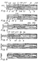
Fig. 1 shows a plan view of the device according to a first preferred embodiment of the present invention with the driving element in the initial position with the door closed; -
Fig. 2 shows the device according toFig. 1 with the driving pin disengaged from the rear slot of the first slider; -
Fig. 3 shows the device ofFig. 1 with the driving pin abutting on the side wall of the front slot of the first slider in the position in which the door has been opened by a quantity suitable to allow the user to grasp it; -
Fig. 4 shows the device ofFig. 1 wherein, through the external action of the user, the driving pin has disengaged from the first slider and the door has been released from the driving element; -
Fig. 5 shows the device ofFig. 1 in the moment in which, during retraction of the driving element, the driving pin impacts against the side wall of the rear slot of the first slider; -
Fig. 6 shows the device ofFig. 1 which, with the door open, shows the driving element back in the initial position; -
Fig. 7 shows a cross section of the device ofFig. 1 along the line 7-7; -
Fig. 8 shows the device ofFig. 1 fitted to the piece of furniture and enclosed in its own cover; -
Fig. 9 shows a plan view of the fixed guide of the device ofFig. 1 ; -
Fig. 10 shows a plan view of the inside of the cover of the fixed guide of the device ofFig. 1 ; -
Fig. 11 shows a plan view of the driving element of the device ofFig. 1 ; -
Fig. 12 shows a side view of the second slider of the device ofFig. 1 ; -
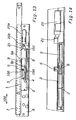
Fig. 13 shows a plan view of the right part of a guide for drawers with the device according to a second preferred manner of producing the present invention; -
Fig. 14 shows a side elevation in enlarged scale of a portion of the device ofFig. 13 ; -
Fig. 15 shows the device ofFig. 13 in a plan view when the drawer (not shown) is in the closed position; -
Fig. 16 shows the device according toFig. 15 after the drawer has been subjected to light pressure which causes it to retract further inside the piece of furniture and causes the slider to move in opposition to the action of the second spring; -
Fig. 17 shows the device ofFig. 13 with the driving pin abutting against the side wall of the front slot of the slider wherein the drawer is open by a quantity to allow it to be grasped by the user; -
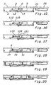
Fig. 18 shows the device ofFig. 13 wherein, through the external action of the user, the driving pin engaged in the front slot of the slider drives it until the guide means are disengaged from the first movement means; -
Fig. 19 shows the device ofFig. 13 with the guide means of the slider engaged in the second movement means and the driving pin disengaged from the slider; -
Fig. 20 shows, with reference to the device ofFig. 13 , a closing step of the drawer wherein the driving pin is engaged with the side wall of the rear slot of the slider; and -
Fig. 21 shows a possible variant of the device according to the invention, wherein the elastically yielding stop has been replaced by a mechanical stop. - In the description, the same reference numbers are used to represented equivalent parts.
- With reference to the first preferred embodiment of the invention shown in
Figures 1-12 . - There is shown a self-closing device for a movable furniture part, according to the invention, indicated as a whole with the
reference number 1. - The
movable furniture part 103 to which this embodiment specifically refers is a door that swings with respect to the body of the piece of furniture, but it could also more generally be a drawer or similar parts. Moreover, as mentioned, the invention could also be applied to the field of general doors for houses or the like. - The
device 1 is preferably associated with afixed guide 8 fastened to thestatic part 116 of the piece of furniture and having a supportingbody 2 for afirst slider 3 which moves reversibly in the direction of asliding axis 100 between a rear end and a front end of agroove 4 in opposition to and through the action of first elastic means, in particular afirst spring 5. - The
groove 4 extends rectilinearly in the direction of thesliding axis 100. - The
first slider 3 is engageable by first driving means present on adriving element 6 which moves reversibly in the direction of thesliding axis 100 between a position retracted in thefixed guide 8 and a position extracted from thefixed guide 8. - In the area of the rear end thereof, the
groove 4 comprises first means for movement of thefirst slider 3 transverse to thesliding axis 100 suitable to engage with specific guide means of thefirst slider 3. - Moreover, in the area of the front end thereof, the
groove 4 comprises second means for movement of thefirst slider 3 transverse to thesliding axis 100 suitable to engage with the guide means of thefirst slider 3. - The first movement means comprise an
intermediate side cavity 10 and arear curve 11 of thegroove 4. Instead, the second movement means comprise afront curve 14 of thegroove 4 which extends from the same part of thegroove 4 in which theintermediate side cavity 10 and therear curve 11 are located. The guide means in turn comprise afront guide pin 12 and arear guide pin 13. - The
front guide pin 12 and respectively therear guide pin 13 are suitable to engage in theintermediate side cavity 10 and respectively in therear curve 11 of thegroove 4, and thefront guide pin 12 is alternatively suitable to engage also in thefront curve 14 of thegroove 4. - The
first slider 3 comprises arear surface slot 109 and afront surface slot 110 in which a drivingpin 106 engages selectively. - The
rear slot 109 and thefront slot 110 respectively haveside walls separation surface 113 between thefront slot 109 and therear slot 110 to intercept thedriving pin 106. - In particular, the
separation surface 113 is flat and theside walls separation surface 113. - The
device 1 is also provided with an elastically yieldingstop 9, fixed to the supportingbody 2, against which thefirst slider 3 rests directly or indirectly before it engages with the guide means thereof in the first movement means of thegroove 4. - The
stop 9, having a main axis oriented in the direction of thesliding axis 100, comprises afixed part 9a and amovable part 9b between which a spring (not shown) is interposed, advantageously having greater elastic strength than that of thefirst spring 5 so that, when thefirst slider 3 is free to slide, it is capable of stopping it in the position corresponding to the closed position of themovable part 103. - The
device 1 also has means 104 for removable coupling between themovable part 103 and thedriving element 6. - The coupling means 104 can indistinctly comprise magnetic or mechanical connection means of known type, for example fitted to the internal side of the
movable part 103 and to the front end of the drivingelement 6. - In the case of magnetic connection, the coupling force exerted by the coupling means must be calibrated so as to allow release thereof as a result of a reasonable force exerted by the user. In the case of connection of mechanical type, the coupling means must allow separation of the elements in the extracted position of the driving
element 6. - In a first preferred embodiment, in which the device is applied to a piece of furniture provided with hinges which exert a push in the closing direction of the
movable part 103, asecond slider 101 is also provided, carried by the fixedguide 8 and which moves reversibly in the direction of the slidingaxis 100 in opposition to and through the action of second elastic means, in particular asecond spring 102. - The
second slider 101 is engageable with second driving means 107 present on the drivingelement 6. In this case the coupling force of the coupling means must be greater than the sum of the elastic return force towards the retracted position exerted indirectly on the drivingelement 6 by the first and second elastic means, and in particular by thefirst spring 5 and by thesecond spring 102. - The driving
element 6 has a rod-shapedmain body 105 and is supported slidingly in aguide element 114 produced in acover 115 of the fixedguide 8. The axis of the rod-shapedmain body 105 extends in the direction of the slidingaxis 100. - The first driving means of the driving
element 6 comprise adriving pin 106 which extends transversely to the rod-shapedmain body 105 and is suitable to engage with thefirst slider 3. - The second driving means of the driving
element 6 comprise atab 107 which extends laterally from the rod-shapedmain body 105 and is constrained to slide in aguide slot 108 produced in thesecond slider 101. - Finally, the
device 1 has anejector 20 supported in the fixedguide 8 behind the drivingelement 6. - The
ejector 20, which comprises afixed part 20a containing amovable spindle 20b, is suitable to act against the rear base of the rod-shapedbody 105 to generate an initial opening movement of themovable part 103 with a force greater than the force exerted thereon by any independent closing devices, such as those integrated in the hinges. The ejection force exerted by theejector 20 is however less than the elastic force of thefirst spring 5. - Advantageously, the
ejector 20 is equipped in a known manner with a device for adjusting the pushing force exerted. - The
ejector 20 also has a main axis oriented in the direction of the slidingaxis 100. - Operation of the device according to the invention appears evident from the description and illustration and, in particular is substantially as follows.
-
Fig. 1 represents the situation of thedevice 1 when themovable part 103 is closed. - In the first step in which the
movable part 103 is closed and coupled with the drivingelement 6, the drivingpin 106 engages in therear slot 109 of thefirst slider 3 which is held in a first idle position in which it rests against the elastically yieldingstop 9, the spring of which is not compressed, but only preloaded in order to hold thefirst slider 3 in position. The rear end of the drivingelement 6 rests against the head of theejector 20 which has thespindle 20b in retracted position, as the force of theejector 20 is less than the force of thefirst spring 5. - In the subsequent second step of return of the driving
element 6, shown inFig. 2 , thefirst slider 3 is made to move back into a second position by an external compression force (i.e. generated by the user) of themovable part 103. - In the second position of the
first slider 3 thefront guide pin 12 and respectively therear guide pin 13 engage in theintermediate side cavity 10 and respectively in therear curve 11 of thegroove 4. Movement of thefirst slider 3 transverse to the slidingaxis 100 causes thedriving pin 106 to disengage from therear slot 109. - In the subsequent third step, shown in
Fig. 3 , the drivingpin 103 is released from therear slot 109 and the drivingelement 6, as a result of the push exerted by theejector 20 and now temporarily no longer opposed by thespring 5 or, naturally, by the user, is extracted to make themovable part 103 perform its initial opening movement which terminates when the drivingpin 106 is intercepted by the projectingside wall 112 of thefront slot 110 of thefirst slider 3. - In the first three steps, the
tab 107 slides freely in itsguide slot 108. - In the subsequent fourth step, shown in
Fig. 4 , as a result of an external pulling force (i.e. generated by the user) on themovable part 103, the drivingpin 106, intercepted by theside wall 112 of thefront slot 110 of thefirst slider 3, firstly drives thefirst slider 3 causing the front 12 and respectively rear 13 guide pin to disengage from theintermediate side cavity 10 and respectively from therear curve 11 of thegroove 4. Movement of thefirst slider 3 transverse to the slidingaxis 100 then causes thedriving pin 106 to engage in thefront slot 110. During the fourth step, after having come into contact with the front end of theguide slot 108, thetab 107 starts to drive thesecond slider 101 to the end of its travel in the position in which the front end of thesecond slider 101 is intercepted by the front wall of the fixedguide 8 and consequently further advance of the drivingelement 6 is blocked. Before thesecond slider 101 reaches the ends of its travel, thefront guide pin 12 engages with thefront curve 14 of thegroove 4 making thefirst slider 3 move transversely to the direction ofmovement 100, as a result of which thedriving pin 106 disengages from thefront slot 110. The coupling force ensured by the coupling means is greater than the sum of the return force caused by thefirst spring 5 and thesecond spring 102, so that the drivingelement 6 can be driven forward. When the drivingelement 6 reaches the end of its travel during extraction, in the case of magnetic connection the pulling force on themovable part 103 becomes predominant with respect to the coupling force ensured by the coupling means, or, in the case of mechanical connection, the coupling means are released from their coupling, themovable part 103 is released from the drivingelement 6 and can be taken to a position of complete opening. - In the subsequent fifth step, shown in
Fig. 5 , thesecond slider 101, through thespring 102, retracts the drivingelement 6 towards the inside of the fixedguide 8. During this step the drivingpin 106, intercepted by theside wall 111 of therear slot 109, initially causes thefirst slider 3 to move transversely to the slidingdirection 100 and thefront guide pin 12 to disengage from thefront curve 14. Consequently, also thefirst slider 3 can be returned, through thespring 5, to the position thereof taken in the first step (Fig. 6 ). - In the case of a piece of furniture having hinges provided with elastic system with push in the opening direction of the swinging furniture part, it is necessary for the driving
element 6 to remain in its extracted position to re-couple the swinging part when it is closed again. Therefore, this type of hinge makes the second slider and the second elastic means superfluous, and allows a decelerator to be provided optionally in place of the ejector to decelerate the closing movement of the swinging part caused by thespring 5 which moves theslider 3 back when it is coupled by the drivingelement 6. The device therefore allows simple and functional opening and closing of a door or drawer facilitating grasping thereof by the user and providing guided closing thereof. - We shall now refer to the second preferred embodiment of the invention shown in
Figs. 13-20 . There is shown a self-closing device for a movable furniture part, according to the invention, indicated as a whole with thereference number 1. Themovable furniture part 103 to which this preferred embodiment specifically refers is a drawer, but it could also more generally be a door that swings with respect to the body of the piece of furniture or similar parts. Moreover, as mentioned the invention could also be applied to the field of general doors for houses or the like. Thedevice 1 comprises, associated with a fixedguide 8, a supportingbody 2 for aslider 3 which moves reversibly along a slidingaxis 100 in opposition to and through the action of first elastic means, in particular afirst spring 5 coupled at one end thereof with aconnection 150 produced on an extension of theslider 3 and at the other end thereof with aconnection 151 produced on an extension of the supportingbody 2. - The
slider 3 is engageable with driving means present on adriving element 6 which moves reversibly in the direction of the slidingaxis 100 integral with anextractable guide 7 of the drawer to which it is fixed. - However, it would also be possible to associated the supporting
body 2 with theextractable guide 7 and the drivingelement 6 with the fixedguide 8. - The supporting
body 2 comprises first means for movement of theslider 3 suitable to engage with specific guide means of the slider so as to release it from the driving means. - An elastically yielding
stop 9 is also present, against which theslider 3 rests directly or indirectly before it engages with the guide means in the first movement means. - The
stop 9, having a main axis oriented in the direction of the slidingaxis 100, comprises afixed part 9a and amovable part 9b between which a spring (not shown) is interposed, advantageously having greater elastic strength than that of thefirst spring 5 so that, when thefirst slider 3 is free to slide, it is capable of stopping it in the position corresponding to the closed position of themovable part 103. - The coupling means comprise a
driving pin 106 which extends transversely to the slidingaxis 100 and is suitable to engage with theslider 3. - The supporting
body 2 has agroove 4 which in the area of the rear end thereof comprises the first means for movement of theslider 3 and in the area of the front end thereof comprises second means for movement of theslider 3 transverse to the slidingaxis 100 suitable to engage with the guide means of theslider 3. - The groove extends rectilinearly in the direction of the sliding
axis 100. - The first movement means comprise an
intermediate side cavity 10 and arear curve 11 of thegroove 4. The second movement means instead comprise afront curve 14 of thegroove 4 which extends from the same part of thegroove 4 in which theintermediate side cavity 10 and therear curve 11 are located. The guide means in turn comprise afront guide pin 12 and arear guide pin 13. - The
front guide pin 12 and respectively therear guide pin 13 are suitable to engage in theintermediate side cavity 10 and respectively in therear curve 11 of thegroove 4, and thefront guide pin 12 is alternatively suitable to engage also in thefront curve 14 of thegroove 4. - The
first slider 3 comprises arear surface slot 109 and afront surface slot 110 in which thedriving pin 106 engages selectively. - The
rear slot 109 and thefront slot 110 respectively haveside walls separation surface 113 between thefront slot 109 and therear slot 110 to intercept the drivingpin 106. - In particular, the
separation surface 113 is flat and theside walls separation surface 113. - An
ejector 20, suitable to move the drawer for initial opening thereof, can be associated with the device. - The
ejector 20 is suitable to interact with astop 21 integral with theextractable guide 7, but its force is lower than the force exerted by thefirst spring 5. - The
ejector 20, which comprises afixed part 20a containing amovable spindle 20b, is provided in a known manner with a device to regulate the pushing force exerted, and also has a main axis oriented in the direction of the slidingaxis 100. - In a constructional variant, not shown, the ejector can be replaced by an adequate inclination, not shown, of the fixed and/or sliding guides of the drawer, along which it can slide through gravity. In a further constructional variant the ejector can be replaced by magnets, not shown here, oriented to generate repulsion forces, capable of allowing the drawer to slide and facilitating, as in the other cases, grasping thereof by the user.
- Operation of the device according to the invention appears evident from the description and illustration and, in particular is substantially as follows.
-
Fig. 15 represents the situation of thedevice 1 when the drawer is closed. The drivingpin 106 engages in therear slot 109 of theslider 3 which is held in a first idle position in which it rests against the elastically yieldingstop 9, the spring of which is not compressed, but only preloaded in order to hold theslider 3 in position. Thestop 21 rests against the head of theejector 20 which has thespindle 20b in retracted position, as the force of theejector 20 is less than the force of thefirst spring 5. - In the subsequent step, shown in
Fig. 16 , theslider 3 is made to move back by an external compression force (i.e. generated by the user) applied to the drawer. In this position of theslider 3 thefront guide pin 12 and respectively therear guide pin 13 engage in theintermediate side cavity 10 and respectively in therear curve 11 of thegroove 4. Movement of theslider 3 transverse to the slidingaxis 100 causes thedriving pin 106 to disengage from therear slot 109. - In the subsequent step, shown in
Fig. 17 , the drivingpin 103 is released from therear slot 109 and, as a result of the push exerted by theejector 20 and now temporarily no longer opposed by thespring 5 or, naturally, by the user, it moves to make the drawer perform its initial opening movement which terminates when the drivingpin 106 is intercepted by the projectingside wall 112 of thefront slot 110 of theslider 3. - In the subsequent step, shown in
Fig. 18 , as a result of an external pulling force (i.e. generated by the user) on the drawer, the drivingpin 106, intercepted by theside wall 112 of thefront slot 110 of theslider 3, firstly drives theslider 3 causing the front 12 and respectively rear 13 guide pin to disengage from theintermediate side cavity 10 and respectively from therear curve 11 of thegroove 4. Movement of theslider 3 transverse to the slidingaxis 100 then causes thedriving pin 106 to engage in thefront slot 110. - During the subsequent step, shown in
Fig. 19 , thefront guide pin 12 engages with thefront curve 14 of thegroove 4 making theslider 3 move transversely to the direction ofmovement 100, as a result of which thedriving pin 106 disengages from thefront slot 110 and proceeds freely to the position of complete opening of the drawer. - In the subsequent closing step, shown in
Fig. 20 , the drawer is pushed closed by the user. During this step the drivingpin 106, intercepted by theside wall 111 of therear slot 109, initially causes theslider 3 to move transversely to the slidingdirection 100 and thefront guide pin 12 to disengage from thefront curve 14. Consequently, theslider 3 can be returned, through thespring 5, to the position thereof taken in the first step (Fig. 15 ). - If the entire system requires to be made more compact, the ejector can be housed on the supporting
body 2 behind the elastically yielding element. - Moreover, as already seen, inclined guides can take the place of the ejectors, rather than magnets or other systems suitable to move the drawer.
- With reference now in particular to
Fig. 21 , the elastically yieldingstop 9 is replaced by a mechanical stop formed by astep 120 of the supportingbody 2 arranged transversely to the direction of theslider 3. Theslider 3 rests with arear wall 119 thereof against thestep 120. By means of a force applied from the outside, on the movable furniture part, thepin 106 integral with theextractable guide 7 is pushed against aninclined surface 118 of theslider 3, which causes lateral movement thereof along thestep 120 and inside theappropriate side slots groove 4, so that thepin 106 is released and theextractable guide 7 can be pushed to open by theejector - In practice, it has been seen how the device according to the invention is particularly advantageous to allow simple and functional opening and closing of a drawer facilitating grasping thereof by the user and providing guided closing thereof.
- The invention thus conceived is susceptible to numerous modifications and variants, all falling within the scope of the inventive concept; moreover, all details can be replaced by technically equivalent elements.
- In practice, the materials used and the sizes can be any according to requirements and to the state of the art.
Claims (18)
- A self-closing device (1) particularly for a movable furniture part (103) combinable with an opening system thereof; comprising a fixed guide (8) having a supporting body (2) in which a first slider (3) can slide reversibly along a sliding axis (100) in opposition to and through the action of first elastic means (5), said first slider (3) being engageable with first driving means comprising a driving pin (106) present on a driving element (6) which slides reversibly in the direction of said sliding axis (100), said supporting body (2) comprising first means for movement of said first slider (3) engageable with guide means of said first slider (3), so as to release it from said driving means, also provided being a mechanical or elastically yielding stop (9, 120) against which said first slider (3) rests directly or indirectly before it engages with said guide means in said first movement means,
said supporting body (2) having groove (4) which in the area of the rear end thereof comprises said first means for movement of said first slider (3) and in the area of the front end thereof comprises second means for movement of said first slider (3) transverse to said sliding axis (100) engageable with said guide means of said first slider (3), characterised in
said first slider (3) comprising a rear slot (109) and a front slot (110) in which said driving pin (106) engages selectively, said front slot (110) and said rear slot (109) having a respective side wall (112, 111) projecting with respect to the surface (113) separating said front slot (110) and said rear slot (109) to intercept said driving pin (106). - The self-closing device (1) according to claim 1, characterized in that said first movement means comprise an intermediate side cavity (10) and a rear curve (11) of said groove (4).
- The self-closing device (1) according to claim 1 or 2, characterized in that said second movement means comprise a front curve (14) of said groove (4) arranged on the same part of said groove (4) in which said intermediate side cavity (10) and said rear curve (11) are located.
- The self-closing device (1) according to one or more of the preceding claims, characterized in that said guide means comprise a front guide pin (12) and a rear guide pin (13), said front guide pin (12) and said rear guide pin (13) being suitable to engage in said intermediate side cavity (10) and in said rear curve (11) of said groove (4), said front guide pin (12) also being suitable alternatively to engage in said front curve (14) .
- The self-closing device (1) according to one or more of the preceding claims, characterized in that said driving element (6) is supported slidingly in a guide element (114) produced in a cover (115) of said fixed guide (8).
- The self-closing device (1) according to one or more of the preceding claims, characterized in that it has removable coupling means (104) between said movable element (103) and said driving element (6).
- The self-closing device (1) according to one or more of the preceding claims, characterized in that it comprises a second slider (101) carried by said fixed guide (8) and which slides reversibly in the direction of said sliding axis (100) in opposition to and through the action of second elastic means (102), said second slider (101) being engageable with second driving means (107) present on said driving element (6).
- The self-closing device (1) according to claim 6 or 7, characterized in that said removable coupling means (104) have a coupling force greater than the sum of the elastic return force exerted indirectly on said driving element (6) by said first (5) and second (102) elastic means.
- The self-closing device (1) according to claim 7, characterized in that said second driving means comprise a tab (107) which extends transversely from said driving element (6) and is constrained to slide in a guide slot (108) produced in said second slider (101).
- The self-closing device (1) according to one or more of the preceding claims, characterized in that said fixed guide (8) supports, behind said driving element (6), an ejector (20) suitable to generate an initial opening movement of said movable part (103).
- The self-closing device (1) according to one or more of the preceding claims, characterized in that said ejector (20) has an' ejection force that is less than the elastic force of said first elastic means (5).
- The self-closing device (1) according to one or more of claims 1 to 6, characterized in that said fixed guide (2) supports, behind said driving element (6), a decelerator suitable to act against the rear base of said driving element (6) to decelerate closing of said movable part (103).
- The self-closing device (1) according to one or more of the preceding claims, characterized in that said driving element (6) can slide reversibly in the direction of said sliding axis (100) integral with an extractable guide (7).
- The self-closing device (1) according to one or more of the preceding claims, characterized in that said first elastic means (5) exert on said slider (3) in contact with said first elastically yielding stop (9) an elastic force that is less than the elastic force generated by said first elastically yielding stop (9).
- The self-closing device (1) according to one or more of the preceding claims, characterized in that said mechanical stop is formed by a step (120) of said supporting body (2) arranged transversely to the direction of said first slider (3), in turn resting with a rear wall (119) thereof against said step (120).
- The self-closing device (1) according to the preceding claim, characterized in that said first slider (3) has an inclined surface (118) against which said driving pin (106) is suitable to be pushed so as to move said first slider (3) laterally along said step (120).
- A piece of furniture provided with a device (1) according to one or more of the preceding claims and having hinges with a device for pushing the movable furniture part in the closing direction.
- A piece of furniture provided with a device (1) according to one or more of the preceding claims and having hinges with a device for pushing the movable furniture part in the opening direction.
Priority Applications (2)
| Application Number | Priority Date | Filing Date | Title |
|---|---|---|---|
| SI200930494T SI2315898T1 (en) | 2008-10-13 | 2009-09-28 | Self-closing and opening device particularly for a movable furniture part |
| PL09778743T PL2315898T3 (en) | 2008-10-13 | 2009-09-28 | Self-closing and opening device particularly for a movable furniture part |
Applications Claiming Priority (3)
| Application Number | Priority Date | Filing Date | Title |
|---|---|---|---|
| ITMI2008A001812A IT1392328B1 (en) | 2008-10-13 | 2008-10-13 | SELF-WELDING DEVICE FOR A MOVABLE PART OF A FURNITURE |
| ITMI2008A001849A IT1392653B1 (en) | 2008-10-17 | 2008-10-17 | AUTO DEVICE CLOSING A MOVABLE PART OF A MOBILE |
| PCT/EP2009/006970 WO2010043306A1 (en) | 2008-10-13 | 2009-09-28 | Self-closing and opening device particularly for a movable furniture part |
Publications (2)
| Publication Number | Publication Date |
|---|---|
| EP2315898A1 EP2315898A1 (en) | 2011-05-04 |
| EP2315898B1 true EP2315898B1 (en) | 2012-11-07 |
Family
ID=41334539
Family Applications (1)
| Application Number | Title | Priority Date | Filing Date |
|---|---|---|---|
| EP09778743A Active EP2315898B1 (en) | 2008-10-13 | 2009-09-28 | Self-closing and opening device particularly for a movable furniture part |
Country Status (12)
| Country | Link |
|---|---|
| US (1) | US8668288B2 (en) |
| EP (1) | EP2315898B1 (en) |
| JP (1) | JP5624547B2 (en) |
| KR (1) | KR20110083625A (en) |
| CN (1) | CN102203367B (en) |
| BR (1) | BRPI0914011A2 (en) |
| ES (1) | ES2397814T3 (en) |
| HK (1) | HK1158721A1 (en) |
| PL (1) | PL2315898T3 (en) |
| SI (1) | SI2315898T1 (en) |
| TW (1) | TWI437967B (en) |
| WO (1) | WO2010043306A1 (en) |
Families Citing this family (25)
| Publication number | Priority date | Publication date | Assignee | Title |
|---|---|---|---|---|
| IT1392907B1 (en) * | 2008-09-12 | 2012-04-02 | Salice Arturo Spa | SELF-CLOSING DEVICE FOR A DRAWER OR A MOVABLE PART OF A FURNITURE |
| DE102008061728A1 (en) * | 2008-12-12 | 2010-06-17 | Dorma Gmbh + Co. Kg | sliding door |
| IT1392184B1 (en) * | 2008-12-12 | 2012-02-22 | Salice Arturo Spa | OPENING AND CLOSING DEVICE FOR A MOVABLE PART OF A FURNITURE |
| JP5433466B2 (en) * | 2010-03-17 | 2014-03-05 | 株式会社ニフコ | Sliding assist device |
| JP2011196015A (en) * | 2010-03-17 | 2011-10-06 | Nifco Inc | Slide assist device |
| AT509934B1 (en) | 2010-05-20 | 2016-01-15 | Blum Gmbh Julius | DRIVE DEVICE FOR MOVING A MOVABLE FURNITURE PART |
| DE202010013193U1 (en) * | 2010-12-22 | 2012-03-26 | Paul Hettich Gmbh & Co. Kg | Opening and closing device for movable furniture parts and ejection device |
| DE102011122266A1 (en) * | 2011-12-23 | 2013-06-27 | Grass Gmbh | Device for influencing the movement of a furniture part, guide unit for moving a furniture part and furniture |
| AT511938B1 (en) * | 2012-01-18 | 2013-04-15 | Blum Gmbh Julius | DRIVE DEVICE FOR A MOVABLE FURNITURE PART |
| AT512509B1 (en) * | 2012-07-10 | 2013-09-15 | Blum Gmbh Julius | Ejecting device for a movable furniture part |
| ITMI20121718A1 (en) * | 2012-10-12 | 2014-04-13 | Salice Arturo Spa | MOBILE WITH AT LEAST ONE DRAWER OR LIKE |
| ES2474290B1 (en) * | 2013-01-08 | 2015-01-02 | Industrias Auxiliares, S.A. (Indaux) | SELF-CLOSURE DEVICE FOR SLIDING MOBILE PARTS |
| AT514143A1 (en) * | 2013-04-12 | 2014-10-15 | Blum Gmbh Julius | Drive device for a movable furniture part |
| DE102013103989A1 (en) * | 2013-04-19 | 2014-11-06 | Hettich-Heinze Gmbh & Co. Kg | guiding device |
| TWI538638B (en) | 2015-11-12 | 2016-06-21 | 川湖科技股份有限公司 | Drive mechanism and method for furniture parts |
| TWI536933B (en) | 2015-11-12 | 2016-06-11 | 川湖科技股份有限公司 | Slide rail assembly |
| TWI532452B (en) | 2015-11-12 | 2016-05-11 | 川湖科技股份有限公司 | Drive mechanism |
| TWI572304B (en) | 2016-03-31 | 2017-03-01 | 川湖科技股份有限公司 | Drive mechanism and method for furniture parts |
| CN107296407B (en) * | 2016-04-13 | 2019-03-15 | 川湖科技股份有限公司 | Furniture assembly and its driving mechanism, method |
| DE102016120593A1 (en) * | 2016-10-27 | 2018-05-03 | Hettich-Oni Gmbh & Co. Kg | Opening and closing system with an ejection device for a furniture and operating method for an opening and closing system |
| CN106361025B (en) * | 2016-11-11 | 2018-12-28 | 伍志勇 | A kind of furniture ejector structure |
| KR102470209B1 (en) * | 2018-04-27 | 2022-11-22 | 엘지전자 주식회사 | Drawer Guide and Laundry Treatment Apparatus having the same |
| WO2019238556A1 (en) * | 2018-06-13 | 2019-12-19 | Wolfgang Held | Device for opening and closing supported covers |
| IT201800011081A1 (en) * | 2018-12-13 | 2020-06-13 | Car S R L | OPENING DEVICE FOR A DOOR OR DRAWER AND CABINET INCLUDING THIS DEVICE |
| US10677512B1 (en) * | 2019-01-31 | 2020-06-09 | Whirlpool Corporation | Appliance push-to-open system and method of installing the push-to-open system |
Citations (1)
| Publication number | Priority date | Publication date | Assignee | Title |
|---|---|---|---|---|
| WO2010028722A2 (en) * | 2008-09-12 | 2010-03-18 | Arturo Salice S.P.A. | Self-closing device for a drawer or for a moveable part of a piece of furniture |
Family Cites Families (19)
| Publication number | Priority date | Publication date | Assignee | Title |
|---|---|---|---|---|
| US3854785A (en) * | 1972-09-16 | 1974-12-17 | Krause Kg Robert | Actuating device |
| AT401717B (en) * | 1993-06-23 | 1996-11-25 | Blum Gmbh Julius | LOCKING DEVICE FOR DRAWERS |
| JP2550377Y2 (en) * | 1993-09-14 | 1997-10-08 | 磯川産業株式会社 | Magnet bush latch |
| IT250443Y1 (en) * | 2000-09-19 | 2003-09-10 | Salice Arturo Spa | DEVICE FOR THE DECELERATED CLOSURE OF SLIDING FURNITURE PARTS |
| JP3996584B2 (en) * | 2003-03-31 | 2007-10-24 | Thk株式会社 | Pull-in device, drawer device and sliding door device |
| MY140924A (en) * | 2003-05-22 | 2010-02-12 | Harn Marketing Sdn Bhd | A drawer stabilizing arrangement for double walled drawer |
| DE20311795U1 (en) * | 2003-07-31 | 2004-11-18 | Alfit Ag | Drawer pull-out guide with automatic retraction with integrated damping |
| ITMC20030144A1 (en) * | 2003-12-05 | 2005-06-06 | Compagnucci Spa Ora Compagnucci Ho Lding Spa | DEVICE FOR AUTOMATIC AND SUSPENSION CLOSING OF DRAWERS AND REMOVABLE FACILITIES FOR FURNITURE. |
| AT503066B1 (en) | 2004-12-03 | 2008-01-15 | Blum Gmbh Julius | DRIVE DEVICE FOR A MOVABLY STORED FURNITURE |
| DE202005009860U1 (en) * | 2004-12-17 | 2006-04-20 | Alfit Ag | Closing and opening device for drawers |
| AT502939A1 (en) * | 2005-04-28 | 2007-06-15 | Blum Gmbh Julius | FURNITURE |
| AT501778B1 (en) * | 2005-04-28 | 2009-11-15 | Blum Gmbh Julius | EJECTION DEVICE FOR A MOVABLE FURNITURE PART |
| EP1785063B1 (en) * | 2005-11-10 | 2012-03-14 | Grass GmbH | Device for opening and closing a movable furniture part and said furniture part |
| JP4806609B2 (en) * | 2005-11-21 | 2011-11-02 | トックベアリング株式会社 | Retraction unit |
| DE102006058639B4 (en) * | 2006-12-11 | 2008-08-14 | Zimmer, Günther | Combined deceleration and acceleration device |
| CN201182372Y (en) * | 2008-03-13 | 2009-01-21 | 佛山市顺德区泰明金属制品厂有限公司 | Drawer sliding rail switching-off devcie |
| DE102008021458A1 (en) * | 2008-04-29 | 2010-01-07 | Zimmer, Günther | Acceleration device with two energy storage devices |
| IT1392184B1 (en) * | 2008-12-12 | 2012-02-22 | Salice Arturo Spa | OPENING AND CLOSING DEVICE FOR A MOVABLE PART OF A FURNITURE |
| US8240788B2 (en) * | 2010-03-04 | 2012-08-14 | Sun Chain Metal Industry Co., Ltd. | Hidden self-closing drawer slide assembly |
-
2009
- 2009-09-28 ES ES09778743T patent/ES2397814T3/en active Active
- 2009-09-28 PL PL09778743T patent/PL2315898T3/en unknown
- 2009-09-28 KR KR1020117008380A patent/KR20110083625A/en not_active Application Discontinuation
- 2009-09-28 WO PCT/EP2009/006970 patent/WO2010043306A1/en active Application Filing
- 2009-09-28 US US13/120,573 patent/US8668288B2/en not_active Expired - Fee Related
- 2009-09-28 BR BRPI0914011A patent/BRPI0914011A2/en not_active IP Right Cessation
- 2009-09-28 CN CN200980140646.7A patent/CN102203367B/en active Active
- 2009-09-28 EP EP09778743A patent/EP2315898B1/en active Active
- 2009-09-28 SI SI200930494T patent/SI2315898T1/en unknown
- 2009-09-28 JP JP2011530394A patent/JP5624547B2/en active Active
- 2009-10-08 TW TW098134117A patent/TWI437967B/en active
-
2011
- 2011-12-08 HK HK11113291.6A patent/HK1158721A1/en unknown
Patent Citations (1)
| Publication number | Priority date | Publication date | Assignee | Title |
|---|---|---|---|---|
| WO2010028722A2 (en) * | 2008-09-12 | 2010-03-18 | Arturo Salice S.P.A. | Self-closing device for a drawer or for a moveable part of a piece of furniture |
Also Published As
| Publication number | Publication date |
|---|---|
| CN102203367B (en) | 2014-09-17 |
| PL2315898T3 (en) | 2013-03-29 |
| JP2012505326A (en) | 2012-03-01 |
| HK1158721A1 (en) | 2012-07-20 |
| CN102203367A (en) | 2011-09-28 |
| BRPI0914011A2 (en) | 2019-09-24 |
| US8668288B2 (en) | 2014-03-11 |
| TW201029603A (en) | 2010-08-16 |
| ES2397814T3 (en) | 2013-03-11 |
| EP2315898A1 (en) | 2011-05-04 |
| WO2010043306A1 (en) | 2010-04-22 |
| SI2315898T1 (en) | 2013-04-30 |
| KR20110083625A (en) | 2011-07-20 |
| US20110254416A1 (en) | 2011-10-20 |
| TWI437967B (en) | 2014-05-21 |
| JP5624547B2 (en) | 2014-11-12 |
Similar Documents
| Publication | Publication Date | Title |
|---|---|---|
| EP2315898B1 (en) | Self-closing and opening device particularly for a movable furniture part | |
| EP2262397B1 (en) | Device for opening and closing a movable part of a furniture unit | |
| EP2320767B1 (en) | Self-closing device for a drawer or for a moveable part of a piece of furniture | |
| CN104135894B (en) | Driving means for movable furniture parts | |
| US8256853B2 (en) | Opening device for a slide assembly | |
| CN101605479B (en) | Ejector of a movable furniture part | |
| US7331643B2 (en) | Piece of furniture with a movable furniture component | |
| EP2532272A1 (en) | Opening mechanism of slide assembly | |
| EP2371241B1 (en) | Slide assembly with an opening device | |
| JP6236235B2 (en) | Storage door opening / closing structure | |
| ES2832658T3 (en) | Drive device for a mobile furniture part and method for opening and closing a mobile furniture part | |
| KR20180036511A (en) | Sliding door opening and closing device | |
| CN103082701A (en) | Automatic closing system used for movable furniture cupboard parts | |
| CN109922694B (en) | Furniture and method for opening drawers and inner drawers | |
| CA2698505C (en) | Opening device for a slide assembly | |
| ES2937730T3 (en) | Drive device for a movable piece of furniture |
Legal Events
| Date | Code | Title | Description |
|---|---|---|---|
| PUAI | Public reference made under article 153(3) epc to a published international application that has entered the european phase |
Free format text: ORIGINAL CODE: 0009012 |
|
| 17P | Request for examination filed |
Effective date: 20110308 |
|
| AK | Designated contracting states |
Kind code of ref document: A1 Designated state(s): AT BE BG CH CY CZ DE DK EE ES FI FR GB GR HR HU IE IS IT LI LT LU LV MC MK MT NL NO PL PT RO SE SI SK SM TR |
|
| AX | Request for extension of the european patent |
Extension state: AL BA RS |
|
| 17Q | First examination report despatched |
Effective date: 20110930 |
|
| DAX | Request for extension of the european patent (deleted) | ||
| GRAP | Despatch of communication of intention to grant a patent |
Free format text: ORIGINAL CODE: EPIDOSNIGR1 |
|
| GRAC | Information related to communication of intention to grant a patent modified |
Free format text: ORIGINAL CODE: EPIDOSCIGR1 |
|
| GRAS | Grant fee paid |
Free format text: ORIGINAL CODE: EPIDOSNIGR3 |
|
| GRAA | (expected) grant |
Free format text: ORIGINAL CODE: 0009210 |
|
| AK | Designated contracting states |
Kind code of ref document: B1 Designated state(s): AT BE BG CH CY CZ DE DK EE ES FI FR GB GR HR HU IE IS IT LI LT LU LV MC MK MT NL NO PL PT RO SE SI SK SM TR |
|
| REG | Reference to a national code |
Ref country code: GB Ref legal event code: FG4D |
|
| REG | Reference to a national code |
Ref country code: AT Ref legal event code: REF Ref document number: 583094 Country of ref document: AT Kind code of ref document: T Effective date: 20121115 Ref country code: CH Ref legal event code: EP |
|
| REG | Reference to a national code |
Ref country code: IE Ref legal event code: FG4D |
|
| REG | Reference to a national code |
Ref country code: DE Ref legal event code: R096 Ref document number: 602009011065 Country of ref document: DE Effective date: 20130103 |
|
| REG | Reference to a national code |
Ref country code: ES Ref legal event code: FG2A Ref document number: 2397814 Country of ref document: ES Kind code of ref document: T3 Effective date: 20130311 |
|
| REG | Reference to a national code |
Ref country code: PL Ref legal event code: T3 |
|
| REG | Reference to a national code |
Ref country code: NL Ref legal event code: VDEP Effective date: 20121107 |
|
| REG | Reference to a national code |
Ref country code: LT Ref legal event code: MG4D |
|
| PG25 | Lapsed in a contracting state [announced via postgrant information from national office to epo] |
Ref country code: NO Free format text: LAPSE BECAUSE OF FAILURE TO SUBMIT A TRANSLATION OF THE DESCRIPTION OR TO PAY THE FEE WITHIN THE PRESCRIBED TIME-LIMIT Effective date: 20130207 Ref country code: HR Free format text: LAPSE BECAUSE OF FAILURE TO SUBMIT A TRANSLATION OF THE DESCRIPTION OR TO PAY THE FEE WITHIN THE PRESCRIBED TIME-LIMIT Effective date: 20121107 Ref country code: SE Free format text: LAPSE BECAUSE OF FAILURE TO SUBMIT A TRANSLATION OF THE DESCRIPTION OR TO PAY THE FEE WITHIN THE PRESCRIBED TIME-LIMIT Effective date: 20121107 Ref country code: FI Free format text: LAPSE BECAUSE OF FAILURE TO SUBMIT A TRANSLATION OF THE DESCRIPTION OR TO PAY THE FEE WITHIN THE PRESCRIBED TIME-LIMIT Effective date: 20121107 Ref country code: NL Free format text: LAPSE BECAUSE OF FAILURE TO SUBMIT A TRANSLATION OF THE DESCRIPTION OR TO PAY THE FEE WITHIN THE PRESCRIBED TIME-LIMIT Effective date: 20121107 Ref country code: LT Free format text: LAPSE BECAUSE OF FAILURE TO SUBMIT A TRANSLATION OF THE DESCRIPTION OR TO PAY THE FEE WITHIN THE PRESCRIBED TIME-LIMIT Effective date: 20121107 Ref country code: IS Free format text: LAPSE BECAUSE OF FAILURE TO SUBMIT A TRANSLATION OF THE DESCRIPTION OR TO PAY THE FEE WITHIN THE PRESCRIBED TIME-LIMIT Effective date: 20130307 |
|
| PG25 | Lapsed in a contracting state [announced via postgrant information from national office to epo] |
Ref country code: PT Free format text: LAPSE BECAUSE OF FAILURE TO SUBMIT A TRANSLATION OF THE DESCRIPTION OR TO PAY THE FEE WITHIN THE PRESCRIBED TIME-LIMIT Effective date: 20130307 Ref country code: GR Free format text: LAPSE BECAUSE OF FAILURE TO SUBMIT A TRANSLATION OF THE DESCRIPTION OR TO PAY THE FEE WITHIN THE PRESCRIBED TIME-LIMIT Effective date: 20130208 Ref country code: BE Free format text: LAPSE BECAUSE OF FAILURE TO SUBMIT A TRANSLATION OF THE DESCRIPTION OR TO PAY THE FEE WITHIN THE PRESCRIBED TIME-LIMIT Effective date: 20121107 Ref country code: LV Free format text: LAPSE BECAUSE OF FAILURE TO SUBMIT A TRANSLATION OF THE DESCRIPTION OR TO PAY THE FEE WITHIN THE PRESCRIBED TIME-LIMIT Effective date: 20121107 |
|
| REG | Reference to a national code |
Ref country code: HU Ref legal event code: AG4A Ref document number: E015743 Country of ref document: HU |
|
| PG25 | Lapsed in a contracting state [announced via postgrant information from national office to epo] |
Ref country code: EE Free format text: LAPSE BECAUSE OF FAILURE TO SUBMIT A TRANSLATION OF THE DESCRIPTION OR TO PAY THE FEE WITHIN THE PRESCRIBED TIME-LIMIT Effective date: 20121107 Ref country code: SK Free format text: LAPSE BECAUSE OF FAILURE TO SUBMIT A TRANSLATION OF THE DESCRIPTION OR TO PAY THE FEE WITHIN THE PRESCRIBED TIME-LIMIT Effective date: 20121107 Ref country code: BG Free format text: LAPSE BECAUSE OF FAILURE TO SUBMIT A TRANSLATION OF THE DESCRIPTION OR TO PAY THE FEE WITHIN THE PRESCRIBED TIME-LIMIT Effective date: 20130207 Ref country code: DK Free format text: LAPSE BECAUSE OF FAILURE TO SUBMIT A TRANSLATION OF THE DESCRIPTION OR TO PAY THE FEE WITHIN THE PRESCRIBED TIME-LIMIT Effective date: 20121107 |
|
| PG25 | Lapsed in a contracting state [announced via postgrant information from national office to epo] |
Ref country code: RO Free format text: LAPSE BECAUSE OF FAILURE TO SUBMIT A TRANSLATION OF THE DESCRIPTION OR TO PAY THE FEE WITHIN THE PRESCRIBED TIME-LIMIT Effective date: 20121107 |
|
| PLBE | No opposition filed within time limit |
Free format text: ORIGINAL CODE: 0009261 |
|
| STAA | Information on the status of an ep patent application or granted ep patent |
Free format text: STATUS: NO OPPOSITION FILED WITHIN TIME LIMIT |
|
| 26N | No opposition filed |
Effective date: 20130808 |
|
| PGFP | Annual fee paid to national office [announced via postgrant information from national office to epo] |
Ref country code: SI Payment date: 20130906 Year of fee payment: 5 Ref country code: HU Payment date: 20130910 Year of fee payment: 5 Ref country code: CZ Payment date: 20130918 Year of fee payment: 5 |
|
| PG25 | Lapsed in a contracting state [announced via postgrant information from national office to epo] |
Ref country code: CY Free format text: LAPSE BECAUSE OF FAILURE TO SUBMIT A TRANSLATION OF THE DESCRIPTION OR TO PAY THE FEE WITHIN THE PRESCRIBED TIME-LIMIT Effective date: 20121107 |
|
| PGFP | Annual fee paid to national office [announced via postgrant information from national office to epo] |
Ref country code: PL Payment date: 20130903 Year of fee payment: 5 |
|
| REG | Reference to a national code |
Ref country code: DE Ref legal event code: R097 Ref document number: 602009011065 Country of ref document: DE Effective date: 20130808 |
|
| PG25 | Lapsed in a contracting state [announced via postgrant information from national office to epo] |
Ref country code: MC Free format text: LAPSE BECAUSE OF FAILURE TO SUBMIT A TRANSLATION OF THE DESCRIPTION OR TO PAY THE FEE WITHIN THE PRESCRIBED TIME-LIMIT Effective date: 20121107 |
|
| REG | Reference to a national code |
Ref country code: CH Ref legal event code: PL |
|
| GBPC | Gb: european patent ceased through non-payment of renewal fee |
Effective date: 20130928 |
|
| REG | Reference to a national code |
Ref country code: FR Ref legal event code: ST Effective date: 20140530 |
|
| REG | Reference to a national code |
Ref country code: IE Ref legal event code: MM4A |
|
| PG25 | Lapsed in a contracting state [announced via postgrant information from national office to epo] |
Ref country code: CH Free format text: LAPSE BECAUSE OF NON-PAYMENT OF DUE FEES Effective date: 20130930 Ref country code: LI Free format text: LAPSE BECAUSE OF NON-PAYMENT OF DUE FEES Effective date: 20130930 Ref country code: GB Free format text: LAPSE BECAUSE OF NON-PAYMENT OF DUE FEES Effective date: 20130928 Ref country code: IE Free format text: LAPSE BECAUSE OF NON-PAYMENT OF DUE FEES Effective date: 20130928 |
|
| PG25 | Lapsed in a contracting state [announced via postgrant information from national office to epo] |
Ref country code: FR Free format text: LAPSE BECAUSE OF NON-PAYMENT OF DUE FEES Effective date: 20130930 |
|
| PG25 | Lapsed in a contracting state [announced via postgrant information from national office to epo] |
Ref country code: CZ Free format text: LAPSE BECAUSE OF NON-PAYMENT OF DUE FEES Effective date: 20140928 |
|
| PG25 | Lapsed in a contracting state [announced via postgrant information from national office to epo] |
Ref country code: SM Free format text: LAPSE BECAUSE OF FAILURE TO SUBMIT A TRANSLATION OF THE DESCRIPTION OR TO PAY THE FEE WITHIN THE PRESCRIBED TIME-LIMIT Effective date: 20121107 |
|
| PG25 | Lapsed in a contracting state [announced via postgrant information from national office to epo] |
Ref country code: MT Free format text: LAPSE BECAUSE OF FAILURE TO SUBMIT A TRANSLATION OF THE DESCRIPTION OR TO PAY THE FEE WITHIN THE PRESCRIBED TIME-LIMIT Effective date: 20121107 Ref country code: TR Free format text: LAPSE BECAUSE OF FAILURE TO SUBMIT A TRANSLATION OF THE DESCRIPTION OR TO PAY THE FEE WITHIN THE PRESCRIBED TIME-LIMIT Effective date: 20121107 |
|
| REG | Reference to a national code |
Ref country code: SI Ref legal event code: KO00 Effective date: 20150504 |
|
| PG25 | Lapsed in a contracting state [announced via postgrant information from national office to epo] |
Ref country code: SI Free format text: LAPSE BECAUSE OF NON-PAYMENT OF DUE FEES Effective date: 20140929 Ref country code: MK Free format text: LAPSE BECAUSE OF FAILURE TO SUBMIT A TRANSLATION OF THE DESCRIPTION OR TO PAY THE FEE WITHIN THE PRESCRIBED TIME-LIMIT Effective date: 20121107 Ref country code: LU Free format text: LAPSE BECAUSE OF NON-PAYMENT OF DUE FEES Effective date: 20130928 |
|
| PG25 | Lapsed in a contracting state [announced via postgrant information from national office to epo] |
Ref country code: HU Free format text: LAPSE BECAUSE OF NON-PAYMENT OF DUE FEES Effective date: 20140929 |
|
| REG | Reference to a national code |
Ref country code: PL Ref legal event code: LAPE |
|
| PG25 | Lapsed in a contracting state [announced via postgrant information from national office to epo] |
Ref country code: PL Free format text: LAPSE BECAUSE OF NON-PAYMENT OF DUE FEES Effective date: 20140928 |
|
| P01 | Opt-out of the competence of the unified patent court (upc) registered |
Effective date: 20230515 |
|
| PGFP | Annual fee paid to national office [announced via postgrant information from national office to epo] |
Ref country code: IT Payment date: 20230921 Year of fee payment: 15 Ref country code: AT Payment date: 20230901 Year of fee payment: 15 |
|
| PGFP | Annual fee paid to national office [announced via postgrant information from national office to epo] |
Ref country code: DE Payment date: 20230927 Year of fee payment: 15 |
|
| PGFP | Annual fee paid to national office [announced via postgrant information from national office to epo] |
Ref country code: ES Payment date: 20231002 Year of fee payment: 15 |