EP2312497A1 - Appareil pour surveillance des alentours d'un véhicule - Google Patents
Appareil pour surveillance des alentours d'un véhicule Download PDFInfo
- Publication number
- EP2312497A1 EP2312497A1 EP10172565A EP10172565A EP2312497A1 EP 2312497 A1 EP2312497 A1 EP 2312497A1 EP 10172565 A EP10172565 A EP 10172565A EP 10172565 A EP10172565 A EP 10172565A EP 2312497 A1 EP2312497 A1 EP 2312497A1
- Authority
- EP
- European Patent Office
- Prior art keywords
- image
- vehicle
- unit
- images
- recognition
- Prior art date
- Legal status (The legal status is an assumption and is not a legal conclusion. Google has not performed a legal analysis and makes no representation as to the accuracy of the status listed.)
- Withdrawn
Links
Images


Classifications
-
- G—PHYSICS
- G06—COMPUTING; CALCULATING OR COUNTING
- G06T—IMAGE DATA PROCESSING OR GENERATION, IN GENERAL
- G06T3/00—Geometric image transformation in the plane of the image
- G06T3/40—Scaling the whole image or part thereof
- G06T3/4038—Scaling the whole image or part thereof for image mosaicing, i.e. plane images composed of plane sub-images
-
- G—PHYSICS
- G06—COMPUTING; CALCULATING OR COUNTING
- G06V—IMAGE OR VIDEO RECOGNITION OR UNDERSTANDING
- G06V10/00—Arrangements for image or video recognition or understanding
- G06V10/20—Image preprocessing
- G06V10/26—Segmentation of patterns in the image field; Cutting or merging of image elements to establish the pattern region, e.g. clustering-based techniques; Detection of occlusion
- G06V10/267—Segmentation of patterns in the image field; Cutting or merging of image elements to establish the pattern region, e.g. clustering-based techniques; Detection of occlusion by performing operations on regions, e.g. growing, shrinking or watersheds
-
- G—PHYSICS
- G06—COMPUTING; CALCULATING OR COUNTING
- G06V—IMAGE OR VIDEO RECOGNITION OR UNDERSTANDING
- G06V20/00—Scenes; Scene-specific elements
- G06V20/50—Context or environment of the image
- G06V20/56—Context or environment of the image exterior to a vehicle by using sensors mounted on the vehicle
- G06V20/58—Recognition of moving objects or obstacles, e.g. vehicles or pedestrians; Recognition of traffic objects, e.g. traffic signs, traffic lights or roads
-
- G—PHYSICS
- G06—COMPUTING; CALCULATING OR COUNTING
- G06V—IMAGE OR VIDEO RECOGNITION OR UNDERSTANDING
- G06V20/00—Scenes; Scene-specific elements
- G06V20/50—Context or environment of the image
- G06V20/56—Context or environment of the image exterior to a vehicle by using sensors mounted on the vehicle
- G06V20/588—Recognition of the road, e.g. of lane markings; Recognition of the vehicle driving pattern in relation to the road
Definitions
- the present invention relates to apparatus for vehicle surroundings monitorings that assists in the checking of the periphery of a vehicle by its passenger by displaying images of the periphery of the vehicle captured by vehicle-mounted cameras.
- a parking aid device comprising: a steering state detection means that detects the steering state of a vehicle; a parking space detection means that detects a parking space through image recognition based on an image from a camera; an predicted path of the vehicle computation means that computes an predicted path of the vehicle based on information from the steering state detection means; and notification means that provides to the driver information that aids parking based on information on the predicted path of the vehicle and the parking space (for example, see JP Patent Publication (Kokai) No. 11-339194 A (1999 ) (Patent Document 1)).
- Patent Document 2 discloses a technique in which tone correction is performed based on the brightness value average of overlapping areas among images captured by plural vehicle-mounted cameras.
- the object of the technique disclosed in Patent Document 2 is to generate an image with a wide dynamic range and good visibility by capturing images with varying exposure amounts while the vehicle is moving, and compositing the thus captured plural images after they have undergone bird-view conversion.
- Patent Document 3 a technique in which images are composited by extracting from images captured by plural cameras partial images with appropriate exposure amounts.
- the object of the technique disclosed in Patent Document 3 is to generate a composite image that is easy to view by extracting, from plural images which are of the same area and taken using plural imaging devices with varying exposure amounts, images that each have an appropriate exposure amount.
- the present invention is made in view of the problems discussed above, and an object thereof is to provide apparatus for vehicle surroundings monitorings that so assists that a passenger may check, with ease, the periphery of a vehicle based on images captured with vehicle-mounted cameras.
- Apparatus for vehicle surroundings monitoring of the present invention that solves the problems above assists a passenger in checking the periphery of a vehicle by displaying an image capturing the periphery of the vehicle
- the periphery check assisting device comprising: imaging units that capture a predetermined range of the periphery of the vehicle with mutually differing exposure amounts; an image recognition unit that performs recognition of a pre-set recognition target by image processing plural images that are captured by the image capturing units and that have mutually differing exposure amounts; an image compositing unit that generates a composite image from images based on a recognition result of the image recognition unit; and a display unit that displays the composite image composited by the image compositing unit.
- the present invention it is possible to improve, in outdoor environments with significant lighting fluctuation, the visibility of objects a driver should pay attention to during parking operations, such as parking frame lines, pedestrians in the periphery of the host vehicle, etc.
- a driver pays attention to various objects during parking operations, and the object paid attention change depending on the scene or task.
- a description will be provided in the present embodiment taking parking frames drawn on the ground as an example.
- objects of interest include a variety of things such as pedestrians and other vehicles traveling in the periphery of the host vehicle, such three-dimensional structures as walls, pillars, linchpins, parked vehicles, etc., dangerous objects such as fallen objects, ditches, etc., and so forth.
- Parking frames 20 In order to drive the host vehicle into a parking space, which is the destination for parking, without fail and make fine adjustments in position and direction, the driver directs his/her attention to the parking frame that constitutes the perimeter of the parking space (see, for example, Fig. 8 and Fig. 10 ).
- Parking frames 20 generally comprise white lines and yellow lines as road surface markings drawn on such ground surfaces as asphalt and concrete road surfaces, etc., and are, as shown in Fig. 10 for example, formed by front lines 21, left/right-side lines 22, and rear lines 23.
- a parking frame recognition process is performed with respect to each of the plural images so obtained as to mutually vary in exposure amount. Areas for which recognition is successful are deemed highly visible for humans as well at their respective exposure amounts, and are used preferentially during image compositing.
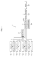
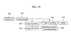
- Fig. 1 is a diagram illustrating the configuration of apparatus for vehicle surroundings monitorings in the present embodiment.
- Apparatus for vehicle surroundings monitorings 1 comprises: plural imaging units 101-104; shutter speed control units 111-114 for controlling the exposure of these imaging units 101-104; an image storage unit 121 that stores images captured by the imaging units 101-104; an image recognition unit 131 that performs a recognition process for a target from the images stored in the image storage unit 121; an image compositing unit 141 that composites an image based on the images stored in the image storage unit 121 and an image recognition result obtained from the image recognition unit 131; and a display unit 151 that displays a composite image obtained from the image compositing unit 141.
- the imaging units 101-104 capture images of a predetermined range in the periphery of the host vehicle, input those images to the image storage unit 121, and comprise, for example, cameras comprising a CCD and a lens. Each of the imaging units 101-104 captures images at mutually differing exposure amounts.
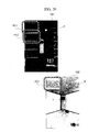
- Fig. 2 is a diagram showing an arrangement example for the imaging units mounted on the vehicle. As shown in Fig. 2 , the imaging unit 101 is disposed at a left portion of a vehicle 10 and serves as a left-side camera that captures leftward of the vehicle 10, and the imaging unit 102 is disposed at a right portion of the vehicle 10 and serves as a right-side camera that captures rightward of the vehicle 10.
- the imaging unit 103 is disposed at a rear portion of the vehicle 10 and serves as a rear camera that captures rearward of the vehicle 10.
- the imaging unit 104 is disposed at a front portion of the vehicle 10 and serves as a front camera that captures forward of the vehicle 10.
- the imaging units 101-104 are so attached to the vehicle 10 that a range of approximately 5 meters around the host vehicle can be captured when parking the vehicle 10 in a parking space such as that shown in Fig. 10 , for example.
- a range of approximately 5 meters around the host vehicle can be captured when parking the vehicle 10 in a parking space such as that shown in Fig. 10 , for example.
- images as those shown in Fig. 11 and Fig. 12 are obtained by the imaging units 101 and 102, for example.
- the vehicle 10 has lights for illuminating the periphery of the host vehicle built into the door mirror portions (none of which are shown).
- the range of 5 meters mentioned above is merely an example, and the range may be changed in accordance with the size of the host vehicle, or the environment of operation.
- the present invention is to be used for purposes of improving the visibility of people in the periphery with respect to such construction machinery as large hydraulic shovels, etc., it would be better to capture a wider range.
- the image storage unit 121 stores, as a set, each image obtained from the imaging units 101-104, the time at which the image was obtained, and its exposure time. In addition, the image storage unit 121 provides to the image recognition unit 131 the most recent images captured by the respective imaging units 101-104. Further, in response to a request from the image compositing unit 141, the image storage unit 121 provides any given stored image, including images that were stored in the past.
- the storage mode of the image storage unit 121 it may be configured with, for example, a memory, such as RAM, a communications interface, and a microcomputer for control, or it may also be configured as, instead of an independent module, a program on a computer.
- an image recognition process that recognizes the parking frames 20 is executed with respect to images of given times and given exposure amounts that are obtained from the imaging units 101-104.
- the results of the parking frame recognition differ for images with differing exposure amounts obtained from, of the imaging units 101-104, the same imaging unit, it is computed, based on the accuracy of the parking frames 20 recognized through the image recognition process, the image area of which exposure amount is suitable for recognition, that is, has better visibility.
- the term "accuracy” refers to the accuracy of recognition of the recognition target by the image recognition unit 131.
- the image compositing unit 141 composites plural images with mutually differing exposure amounts based on the levels of visibility (accuracy) of the image areas computed at the image recognition unit 131.
- the images are composited for each of the imaging units 101-104, and one composite image is generated for each of the imaging units 101-104.
- a host vehicle periphery composite image (see Fig. 20 , for example) with good visibility is generated.
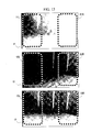
- FIG. 13 is a diagram showing examples of images captured on the left side of the vehicle, and there are shown an image I1 captured at an exposure amount E1, an image I2 captured at an exposure amount E2, and an image 13 captured at an exposure amount E3.
- the image I1 captured at the exposure amount E1 has good visibility in the left-side area of the image, but has poor visibility in the right-side area of the image.
- the image I2 captured at the exposure amount E2 has good visibility in the right-side area of the image, but has poor visibility in the left-side area of the image.
- the image I3 which is a composite image wherein the left-side area of the image I1 and the right-side area of the image I2 have been composited, is generated by the image compositing unit 141.
- the image compositing unit 141 it is possible to improve the visibility of the parking frames 20, which are recognition targets within the composite image I3.
- the image compositing unit 141 joins and composites the composite images respectively created for the imaging units 101-104, and generates the host vehicle periphery composite image, which is a bird-view image comparable to one that might be captured from right above the vehicle 10.
- the display unit 151 is a device for presenting to the driver, who is the user in this case, the host vehicle periphery composite image generated at the image compositing unit 141. It is a device that is capable of presenting visual information to a user, such as a driver, etc., examples of which may include a monitor of a car navigation system, a monitor built into the rear-view mirror, a projector device that is adapted to project onto the windshield, etc.
- each of the imaging units 101-104 may be optimized so as to be improved by, with respect to the area of each of the imaging units 101-104, first compositing images of plural exposure amounts, and then joining and compositing the composite images of the respective imaging units 101-104.
- a vehicle information providing unit 161 may be, as extension units, a vehicle information providing unit 161, and an exposure amount information holding unit.
- the vehicle information providing unit 161 and the exposure amount information holding unit above are used to improve the processes by the image recognition unit 131 and the image compositing unit 141.
- the relative host vehicle position in each of the captured images is computed from information of sensors mounted on the vehicle 10, such as a vehicle speed sensor, wheel speed sensor, steering angle sensor, wheel angle sensor, host vehicle position measuring system, etc., and is added to the information as of when images are stored in the image storage unit 121.
- stop lamp activation information may also be added to the information as of when the images are stored in the image storage unit 121 and be used in the compositing process at the image compositing unit 141.
- headlamp activation information and/or wiper activation information since it can be inferred that the external lighting conditions would most likely be dark and the captured images unclear, thereby indicating that clear feature points will not readily manifest themselves during the compositing of the plural images, by adding them, too, to the information as of when the images are stored in the image storage unit 121, they may be used in the compositing process at the image compositing unit 141.
- the exposure amount information holding unit stores information regarding exposure amount for each of the images captured by the imaging units 101-104. By determining, based on the chronologically stored exposure amounts of each of the imaging units 101-104 and on the success/failure of recognition at the image recognition unit 131, how to subsequently alter exposure amount, the image recognition unit 131 is able to determine the optimal combination of exposure amounts, control shutter speed through the shutter speed control units 111-114, and specify the exposure amount for each of the imaging units 101-104.
- the exposure amount information holding unit may also be provided within the image storage unit 121.
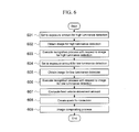
- the imaging units 101-104 capture images of the periphery of the vehicle at varying times and plural varying exposures as specified by the shutter speed control units 111-114.
- the obtained images and the parameters at the time of capture are stored in the image storage unit 121.
- shutter speed In the parameters at the time of capture are included shutter speed, time of capture, and vehicle information at the time of capture.
- vehicle information refers to information that is exchanged among plural devices of the vehicle 10 through a network internal to the vehicle, such as vehicle speed, wheel speed, steering angle, wheel angle, host vehicle position by a host vehicle positioning system, headlamp activation information, wiper activation information, and the like, and also includes information that is exchanged with the host vehicle through vehicle-vehicle communications and road-vehicle communications.
- This process of parking frame recognition comprises two stages, namely, the recognition of line segments that form the parking frames 20, and a determination as to whether or not a combination of the line segments are appropriate as the parking frames 20.
- the recognition of line segments by applying Sobel filters of the vertical direction and the horizontal direction relative to the image, extracting edge points within the image through binarization at an appropriate threshold, and applying the Hough transform to a group of coordinates of the extracted edge points, it is possible to extract a group of edge points aligned linearly.
- the area therebetween may be determined as being parking frames 20 in which the vehicle 10 may be parked.
- This parking frame recognition is performed with respect to images of plural varying exposure amounts. However, for images whose shutter speed control is inappropriate in relation to the peripheral environment of the host vehicle, the edge points within the images mentioned above are not extracted.
- the accuracy of parking frame recognition is computed based on how clearly edge points were detected, how accurate linearity was when the Hough transform was performed, etc.
- indicators are so set as to indicate that the parking frame recognition was clearly successful the higher this accuracy is. As discussed above, it can be inferred that areas in which targets can be recognized clearly through image recognition would have high visibility for people as well. Thus, the position at which the parking frames 20 detected within an image of given exposure are present and the accuracy of the detected parking frames 20 are obtained from the image recognition unit 131 as outputs.
- signals are sent to the shutter speed control unit 111-114 so as to capture at one different exposure from among plural pre-set levels of shutter speed. It is noted that if the vehicle information providing unit 161 is present, a head lamp activation signal and/or the wiper activation status is/are checked, and signals are sent to the shutter speed control units 111-114 so that when the peripheral environment is dark, shutter speed is made slower to obtain brighter images.
- images with differing exposure amounts are composited based on image areas in which the parking frames 20 recognized at the image recognition unit 131 are present, and the accuracy of recognition, i.e., the level of visibility, thereof.
- this compositing first, there is created a weight map which represents how each area of each image is to be used with how much weight among images that have been aligned taking into consideration the movement amounts among images.
- the luminance values and color information (hue, saturation) of the respective pixels of plural images are mixed to create a composite image.
- color information is often missing in images of poor visibility, it is also possible to have only the luminance value information be subject to mixing, and use the values of color information from images with high saturation.
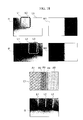
- Fig. 18 is a diagram showing examples of weight maps.
- Weight maps M1 and M2 indicate how recognizable an image each region in each of the images I1 and I2 is, and are grayscale images where the white parts in the diagram represent higher visibility as compared to images of different exposure, and where the black parts represent lower visibility.
- the output image 13 is obtained.
- an image compositing map C1 is generated.
- the method of computing detection accuracy will be described later.
- the image compositing map C1 defines in a continuously varying manner how each image is to be used in what proportion in performing image compositing, wherein: area A1 is an area where 100 % of the image I1 is to be used; area A2 is an area where 51-99 % of the image I1 is to be used with the remainder being the image I2; area A3 is an area where 50 % each of the image I1 and the image I2 are to be used; area A4 is an area where 51-99 % of the image I2 is to be used with the remainder being the image I1; and area A5 is an area where 100 % of the image I2 is to be used.
- bird-view conversion is performed by performing distortion correction, and joining and compositing them taking into consideration the relationship among the imaging units 101-104.
- a host vehicle periphery composite image with high visibility is generated.
- the term "bird-view conversion” refers to a kind of image conversion method wherein, as shown in Fig. 9 , based on the images obtained by the imaging units 101-104 and assuming all points within the images lie on a road surface G, conversion is performed as if one were viewing downward from a virtual camera viewpoint 105. Since this method of generating a host vehicle periphery composite image is a known technique, a description thereof will not be provided in particular herein.
- signals for capturing images by controlling the imaging units 101-104 to adjust their shutter speeds in accordance with signals from the image recognition unit 131 are sent.
- the image compositing unit 141 from mask images at the respective exposures obtained from the image recognition unit 131 and from camera images at corresponding exposures obtained from the image storage unit 121, an image is composited in accordance with the weights of the mask images and sent to the display unit 151.
- compositing is performed after correcting for the movement amount of the host vehicle with respect to the bird-view image.
- the host vehicle movement amount may be found by, instead of from a wheel speed sensor, a vehicle speed sensor, a positioning sensor, etc., computing optical flow from images.
- the display unit 151 may be, for example, a liquid crystal monitor, a display unit that projects onto the windshield, or the like, and displays an image obtained from the image compositing unit 141.
- Fig. 6 is a flowchart showing the flow of the process described above.
- the accuracy of parking frames may be defined as the sum of accuracy Rimg of image information and accuracy Rstr of structural information of a recognition target.
- Accuracy Rimg of image information may be defined by way of the contrast and sharpness of an image area near a parking frame line.
- An image area near a parking frame line may be defined as, for example in the case of a parking frame line and assuming that the parking frame line has a width of W and a length of L, an area of 3 W in width and L in length about a central axis of the parking frame line such that the area includes on both sides an area of the road surface having a width that is comparable to that of the frame line.
- the contrast of an image area may be defined as the ratio of maximum luminance value Ymax included in that area to minimum luminance value Ymin, that is, Ymax/Ymin. It is an indicator that indicates how much of a contrast the parking frame line, which is the target of interest, and the road surface can be recognized with, and assumes a lesser value when the visibility of the image is poor. Sharpness is, considering a straight line that is perpendicular to the boundary between the frame line area and the road surface, the inverse of the distance between extreme values when quadratic differentials of luminous values are taken along this straight line. In the case of an image with poor visibility where the boundary is blurred, this numerical value will be small.
- accuracy Rstr of structural information of a recognition target may be defined as an evaluation indicator for the apparent shape obtained from an image, such as distortions with respect to the linearity, parallelism, and perpendicularity of frame lines.
- Distortion with respect to the linearity of frame lines may be defined as the sum of squares of the distance from an approximate straight line, which is computed through a Hough transform or the like with respect to the coordinates of the above-mentioned group of edge points, up to each of the edge points.
- Distortion with respect to the parallelism of frame lines may be defined as, for example in a case where a parking frame comprises two line segments, cos ⁇ , assuming that the angle formed between each line segment and the approximate straight line is ⁇ (where 0 ⁇ ⁇ ⁇ 90 [deg]).
- distortion with respect to the perpendicularity of frame lines may be defined as, for example in a case where a parking frame comprises two line segments, assuming a line connecting the end points on the parking frame entrance side of the respective frame lines, cos ⁇ , assuming that the angle formed between this line and the approximate straight line of each frame line is ⁇ (where 0 ⁇ ⁇ ⁇ 90 [deg]). It is noted that in a case where a parking frame comprises four line segments, they may similarly be defined as cosines of the angles formed between the approximate straight lines of the respective frame lines. All of these values decrease when distortion is greater.
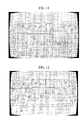
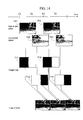
- FIG. 14 A case is considered where parking frame recognition is performed with respect to four images 701-704 taken at different times with the same imaging unit.
- the image 701 is an image captured at time T1 with a given exposure amount E1
- the image 702 is an image captured at time T2, which is different from the time at which the image 701 is captured, with an exposure amount E2.
- the image 703 is an image captured at time T3 with exposure amount E3, which are different from those of the images 701 and 702
- the image 704 is an image captured at time T4 with exposure amount E4, which are different from those of the images 701-703.
- a parking frame line recognition process is performed with respect to each of the images 701-704, and the area of the recognition result thereof and the accuracy of the parking frame are sent to the image compositing unit 141.
- the image compositing unit 141 For example, in Fig. 15 , two parking frames P11 and P12 are recognized in the image 701, one parking frame P21 is recognized in the image 702, and the accuracies of parking frame recognition associated therewith are respectively denoted R11, R12 and R21 (where R11 ⁇ R21).
- the weight of the area corresponding to the parking frame P11 within 711 may be defined as being R11/(R11+R21), and the weight of the area corresponding to the parking frame P21 within 712 as being R21/(R11+R21).
- both exposure amount E1 and exposure amount E2 are appropriate for this area, the image with better visibility turned out to be the image 702.
- the weight of an area in which parking frames could not be recognized in any of the images 701 and 702 can be determined by letting weights be propagated in accordance with the distances from areas for which weights have been determined.
- the weight of point P may be defined as follows, varying the weight in accordance with the ratio of distances from weights that have been determined:
- the image recognition unit 131 may also comprise a function of composite image brightness stabilization with respect to timeline.
- weight maps may be retained per exposure amount so that weightings would not change abruptly.
- W(t-1,E1) and W(t-1,E2) are the respective weight maps for exposure amounts E1 and E2 at time t-1 and where W(t,E1) and W(t,E2) are the respective weight maps for exposure amounts E1 and E2 at time t that are computed in the manner mentioned above, by having the weight maps at time t for use in image compositing be:
- This apparent movement amount may be computed by computing the motion of the images through, for example, feature point tracking by an optical flow method or SIFT (Scale-Invariant Feature Transform).
- Fig. 3 is a diagram showing a configuration in the case of one camera.
- the role of the vehicle information providing unit 161 is to provide information for performing more appropriate image compositing by obtaining from sensor information the movement amount and peripheral environment of the host vehicle.
- the role of the exposure amount information holding unit is to store exposure amounts for past images captured by each of the imaging units 101-104, plan what level of exposure amount each of the imaging units should subsequently capture images with, and specify exposure amounts to the shutter speed control units 111-114.
- the shutter speed setting may be reset to some typical value.
- the configuration may just as well be one in which, for example, the coefficient of gamma transform, or the threshold of binarization or edge detection is changed.
- processing may be executed while sequentially changing the threshold for when it is assumed that an image of a greater exposure amount is inputted and the coefficient of gamma transform and the threshold for when it is assumed that an image of a lesser exposure amount is inputted.
- the configuration may also be such that a brightness correction parameter holding unit 510 is provided, and that there are held plural parameters for correcting the exposure amount of an image during image recognition by the image recognition unit 131.
- Fig. 4 is a block diagram showing a modification example of Fig. 3 .
- the periphery check assisting device 1 shown in Fig.4 is of such a configuration that no control can be effected with respect to the shutter speed control unit 110.
- An explanation will be provided chiefly with respect to how it differs from Fig. 3 .
- the shutter speed control unit 110 sends plural pre-defined shutter speeds to the imaging unit 100 as well as to the image recognition unit 131.
- Fig. 5 is a block diagram showing another modification example of Fig. 3 .
- the periphery check assisting device 1 shown in Fig. 5 has such a configuration that it comprises two each of the imaging unit 100, the shutter speed control unit 110, and the image storage unit 121. A description will be provided chiefly with respect to how it differs from Fig. 3 .
- the image recognition unit 131 outputs control signals of differing shutter speeds to the respective shutter speed control units 110. Thus, plural images with differing exposure taken at the same time are obtained.
- the present invention is applicable to both a configuration with one imaging unit, as well as to a configuration with plural imaging units.
- a feature of the present embodiment is that, first, a host vehicle periphery composite image is generated by joining and compositing images captured by plural imaging units and, next, image recognition is performed with respect to plural host vehicle periphery composite images whose exposure amounts are mutually different, and images of plural exposure amounts are composited in accordance with the recognition result.
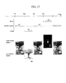
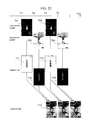
- FIG. 20 A description will be provided using Fig. 20 .
- plural images with mutually differing exposure amounts are captured at the respective imaging units 101-104. These plural images undergo distortion correction, and are joined and composited taking into account the relationship among the respective imaging units 101-104.
- an image 701 is generated by joining and compositing four images with small exposure amounts captured by setting shutter speed to high speed.
- an image 702 is generated by joining and compositing four images with large exposure amounts captured by setting shutter speed to low speed.
- the image 701 and the image 702 are images in which the exposure amounts among the respective imaging units 101-104 are substantially coordinated.
- the fact that parking frame recognition is performed with respect to the images 701 and 702 and that an image of different exposure is generated in accordance with the result thereof is similar to the above-mentioned image compositing method for each camera image.
- an output image 715 is obtained.
- host vehicle periphery composite images are generated by joining and compositing images captured with the respective imaging units 101-104. Then, plural host vehicle periphery composite images with mutually differing exposure amounts are thereafter composited.
- the target of interest is a moving body (a pedestrian) that is moving in the periphery of the host vehicle.
- the contrast between a moving body and a road surface is generally lower than the contrast between white lines of a parking frame and a road surface. Therefore, when images are composited simply on the basis of the contrast of a given area range as is done in conventional techniques, there is a problem in that an image with poor contrast for targets the driver should be mindful of is generated. If the target of interest is stationary, this problem may be solved by the first embodiment described above. However, if the object is in motion, the first embodiment cannot be applied as is.
- a recognition process is performed on each of images obtained at plural exposure amounts.
- a moving body is tracked, and even when recognition is unsuccessful, the position to which it has moved is estimated.
- By appropriately adjusting the brightness and contrast of the estimated position it is possible to generate an image with high visibility.
- the camera arrangement and the device configuration, per se are similar to those in the first embodiment, and descriptions thereof are therefore omitted herein.
- the imaging units 101-104 capture images of the periphery of the vehicle at varying times and plural varying exposures as specified by the shutter speed control units 111-114.
- the obtained images and the parameters at the time of capture are sent to and stored in the image storage unit 121.
- the images stored in the image storage unit 121 are sent to the image recognition unit 131, and a moving body recognition process is executed.
- this moving body recognition is capable of extracting an area where a change occurred as a moving body area.
- the host vehicle is in motion, by detecting the motion vector of the image using an optical flow method and performing segmentation based on the direction and size of that motion vector, it is possible to separate and derive a road surface area and a moving body area.
- This moving body recognition is performed on images of plural varying exposure amounts.
- images whose shutter speed control is inappropriate relative to the environment in the periphery of the host vehicle since luminance values are saturated on the bright or dark side, no difference or motion vector is extracted.
- the image recognition unit 131 computes the accuracy of moving body recognition.
- the position at which the moving body is present as detected from an image of given exposure, and the accuracy of the detected moving body are obtained from the image recognition unit 131 as outputs.
- images of varying exposure amounts are composited at the image compositing unit 141.
- the shutter speed control units 111-114 send signals for capturing images by controlling the imaging units 101-104 so as to adjust shutter speed in accordance with signals from the image recognition unit 131.
- an image is composited based on the result from the image recognition unit 131 and sent to the display unit 151, where the composite image is displayed.
- the accuracy of moving body recognition may be defined as the sum of accuracy Rimg of image quality information and accuracy Rstr of shape information of the recognition target.
- Accuracy Rimg of image quality information may be defined by way of the contrast within and near the moving body area and the complexity of texture. Taking, for example, an area which is the moving body area expanded by 10 % or so, the contrast within and near the moving body area may be defined as the ratio of maximum luminance value Ymax contained in this area to minimum luminance value Ymin, that is, Ymax/Ymin.
- the complexity of texture is so defined that the values become greater with increased complexity. As these are common image processing methods, detailed descriptions are omitted herein.
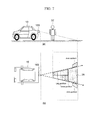
- Accuracy Rstr of shape information of the recognition target can be defined by way of the recognized shape of a person. For example, as shown in Figs. 7(a) and (b) , a person 32 standing behind the vehicle 10 with his/her legs closed (see Fig. 7(a) ) is observed, in a bird-view image 38, as a fan-like shape 35 with his/her feet position as a point of reference (see Fig. 7(b) ).
- the feet position lies in the plane of the ground surface, and can be converted into its size in real space from the size in the image.
- Accuracy Rstr may be so defined as to be higher when such shape and size agree with a model of a standard person's size.
Applications Claiming Priority (1)
| Application Number | Priority Date | Filing Date | Title |
|---|---|---|---|
| JP2009226373A JP4970516B2 (ja) | 2009-09-30 | 2009-09-30 | 周囲確認支援装置 |
Publications (1)
| Publication Number | Publication Date |
|---|---|
| EP2312497A1 true EP2312497A1 (fr) | 2011-04-20 |
Family
ID=43479228
Family Applications (1)
| Application Number | Title | Priority Date | Filing Date |
|---|---|---|---|
| EP10172565A Withdrawn EP2312497A1 (fr) | 2009-09-30 | 2010-08-11 | Appareil pour surveillance des alentours d'un véhicule |
Country Status (3)
| Country | Link |
|---|---|
| US (1) | US8289391B2 (fr) |
| EP (1) | EP2312497A1 (fr) |
| JP (1) | JP4970516B2 (fr) |
Cited By (8)
| Publication number | Priority date | Publication date | Assignee | Title |
|---|---|---|---|---|
| WO2013034140A1 (fr) * | 2011-09-08 | 2013-03-14 | Continental Teves Ag & Co. Ohg | Procédé et dispositif pour un système d'assistance d'un véhicule servant à exécuter une manœuvre autonome ou partiellement autonome |
| EP2744694A4 (fr) * | 2011-08-17 | 2015-07-22 | Lg Innotek Co Ltd | Caméra destinée à un véhicule |
| US9969330B2 (en) | 2013-06-26 | 2018-05-15 | Conti Temic Microelectronic Gmbh | Mirror substitute device and vehicle |
| US10000155B2 (en) | 2013-07-23 | 2018-06-19 | Application Solutions (Electronics and Vision) Ltd. | Method and device for reproducing a lateral and/or rear surrounding area of a vehicle |
| WO2018215369A1 (fr) * | 2017-05-22 | 2018-11-29 | Continental Automotive Gmbh | Unité caméra mobile pour un système de caméra de recul |
| CN110225236A (zh) * | 2018-03-02 | 2019-09-10 | 富士通株式会社 | 为视频监控系统配置参数的方法、装置和视频监控系统 |
| WO2020240323A1 (fr) * | 2019-05-31 | 2020-12-03 | Ricoh Company, Ltd. | Système d'imagerie, procédé d'imagerie et moyens de support |
| US11403770B2 (en) | 2017-11-08 | 2022-08-02 | Clarion Co., Ltd. | Road surface area detection device |
Families Citing this family (37)
| Publication number | Priority date | Publication date | Assignee | Title |
|---|---|---|---|---|
| JP4970381B2 (ja) * | 2008-08-08 | 2012-07-04 | 株式会社東芝 | 特徴抽出装置、特徴抽出方法、画像処理装置、及び、プログラム |
| JP2013018406A (ja) * | 2011-07-12 | 2013-01-31 | Fujitsu Ten Ltd | 駐車枠の認識装置、駐車枠の認識方法、及び、プログラム |
| JP5682788B2 (ja) * | 2011-09-27 | 2015-03-11 | アイシン精機株式会社 | 車両周辺監視装置 |
| DE102011084993A1 (de) * | 2011-10-21 | 2013-04-25 | Robert Bosch Gmbh | Übernahme von Daten aus bilddatenbasierenden Kartendiensten in ein Assistenzsystem |
| WO2013094242A1 (fr) * | 2011-12-19 | 2013-06-27 | 日産自動車株式会社 | Dispositif de détection d'objets |
| US9598836B2 (en) | 2012-03-29 | 2017-03-21 | Harnischfeger Technologies, Inc. | Overhead view system for a shovel |
| IN2015KN00339A (fr) * | 2012-07-27 | 2015-07-10 | Nissan Motor | |
| JP2014039169A (ja) * | 2012-08-16 | 2014-02-27 | Sony Corp | 画像処理装置、および画像処理方法、並びにプログラム |
| CN104822566B (zh) * | 2012-11-27 | 2016-07-06 | 歌乐牌株式会社 | 车载图像处理装置 |
| US9715633B2 (en) | 2012-11-27 | 2017-07-25 | Clarion Co., Ltd. | Vehicle-mounted image processing device |
| WO2014164847A1 (fr) | 2013-03-12 | 2014-10-09 | Boston Scientific Scimed, Inc. | Dispositif d'extraction et procédés d'utilisation associés |
| JP2014203114A (ja) * | 2013-04-01 | 2014-10-27 | 株式会社デンソー | 物体認識装置 |
| JP6032141B2 (ja) * | 2013-07-02 | 2016-11-24 | 株式会社デンソー | 走行路面標示検知装置および走行路面標示検知方法 |
| WO2015026874A1 (fr) | 2013-08-19 | 2015-02-26 | Nant Holdings Ip, Llc | Reconnaissance métrique, systèmes et procédés |
| KR101511992B1 (ko) * | 2013-09-06 | 2015-04-14 | 현대모비스(주) | 조향 휠 제어 방법 및 이를 위한 위한 시스템 |
| KR101511853B1 (ko) * | 2013-10-14 | 2015-04-13 | 영남대학교 산학협력단 | 단일 다중 노출 카메라를 이용한 야간 전방 차량 검출 및 위치 측정 시스템 및 방법 |
| JP6303090B2 (ja) * | 2014-03-24 | 2018-04-04 | アルパイン株式会社 | 画像処理装置および画像処理プログラム |
| US10328932B2 (en) * | 2014-06-02 | 2019-06-25 | Magna Electronics Inc. | Parking assist system with annotated map generation |
| EP3007099B1 (fr) * | 2014-10-10 | 2022-12-07 | Continental Autonomous Mobility Germany GmbH | Système de reconnaissance d'image pour véhicule et procédé correspondant |
| US9626760B2 (en) * | 2014-10-30 | 2017-04-18 | PathPartner Technology Consulting Pvt. Ltd. | System and method to align and merge differently exposed digital images to create a HDR (High Dynamic Range) image |
| WO2016073590A1 (fr) * | 2014-11-06 | 2016-05-12 | Gentex Corporation | Système et procédé de détection de plage de visibilité |
| JP6774948B2 (ja) * | 2015-07-29 | 2020-10-28 | 京セラ株式会社 | 判定装置、車両および判定方法 |
| US11691619B2 (en) * | 2015-08-12 | 2023-07-04 | Hyundai Motor Company | Automatic parking system and automatic parking method |
| JP6555056B2 (ja) * | 2015-09-30 | 2019-08-07 | アイシン精機株式会社 | 周辺監視装置 |
| JP6368958B2 (ja) * | 2016-05-12 | 2018-08-08 | 本田技研工業株式会社 | 車両制御システム、車両制御方法、および車両制御プログラム |
| DE102016114168A1 (de) * | 2016-08-01 | 2018-02-01 | Connaught Electronics Ltd. | Verfahren zum Erfassen eines Objekts in einem Umgebungsbereich eines Kraftfahrzeugs mit Vorhersage der Bewegung des Objekts, Kamerasystem sowie Kraftfahrzeug |
| JP2018092596A (ja) * | 2016-11-30 | 2018-06-14 | 株式会社リコー | 情報処理装置、撮像装置、機器制御システム、移動体、情報処理方法、およびプログラム |
| US11203295B2 (en) * | 2017-04-14 | 2021-12-21 | Panasonic Automotive Svstems Company of America, Division of Panasonic Corporation of North America | Rearview head up display |
| JP2019151304A (ja) * | 2018-03-06 | 2019-09-12 | アイシン精機株式会社 | 周辺監視装置 |
| JP7296768B2 (ja) * | 2019-04-22 | 2023-06-23 | フォルシアクラリオン・エレクトロニクス株式会社 | 画像処理装置及び画像処理方法 |
| JP7300316B2 (ja) * | 2019-05-30 | 2023-06-29 | 株式会社デンソーテン | 移動物検出装置 |
| CN112243089B (zh) * | 2019-07-17 | 2022-05-13 | 比亚迪股份有限公司 | 摄像头hdr图像效果开关控制方法、装置、后视镜、车辆及存储介质 |
| WO2021125076A1 (fr) * | 2019-12-18 | 2021-06-24 | ソニーセミコンダクタソリューションズ株式会社 | Dispositif de traitement d'informations, procédé de traitement d'informations, programme, dispositif de capture d'image et système de capture d'image |
| JP7331731B2 (ja) * | 2020-02-21 | 2023-08-23 | トヨタ自動車株式会社 | 車両用電子ミラーシステム |
| JP7465726B2 (ja) * | 2020-05-28 | 2024-04-11 | フォルシアクラリオン・エレクトロニクス株式会社 | 駐車支援装置、及び駐車支援装置の制御方法 |
| CN111915520B (zh) * | 2020-07-30 | 2023-11-10 | 黑芝麻智能科技(上海)有限公司 | 用于改善拼接图像的亮度的方法、装置和计算机设备 |
| CN117078799A (zh) * | 2023-07-31 | 2023-11-17 | 零束科技有限公司 | 一种基于bev图像的特殊泊车位合成方法及装置 |
Citations (10)
| Publication number | Priority date | Publication date | Assignee | Title |
|---|---|---|---|---|
| US5961571A (en) * | 1994-12-27 | 1999-10-05 | Siemens Corporated Research, Inc | Method and apparatus for automatically tracking the location of vehicles |
| JPH11339194A (ja) | 1998-05-28 | 1999-12-10 | Aisin Seiki Co Ltd | 駐車補助装置 |
| JP3297040B1 (ja) | 2001-04-24 | 2002-07-02 | 松下電器産業株式会社 | 車載カメラの画像合成表示方法及びその装置 |
| JP2004096488A (ja) | 2002-08-30 | 2004-03-25 | Fujitsu Ltd | 物体検知装置、物体検知方法および物体検知プログラム |
| WO2004034183A2 (fr) * | 2002-08-21 | 2004-04-22 | Gentex Corporation | Procedes d'acquisition et de traitement d'images pour commande automatique de l'eclairage exterieur d'un vehicule |
| WO2006022630A1 (fr) * | 2004-07-26 | 2006-03-02 | Silicon Optix, Inc. | Systeme est procede de vision panoramique |
| US20060203092A1 (en) * | 2000-04-28 | 2006-09-14 | Matsushita Electric Industrial Co., Ltd. | Image processor and monitoring system |
| EP1775691A1 (fr) * | 2004-05-19 | 2007-04-18 | HONDA MOTOR CO., Ltd. | Appareil de reconnaissance de limite de voie pour véhicule |
| US20070225913A1 (en) * | 2005-05-17 | 2007-09-27 | Tetsuo Ikeda | Traffic Lane Marking Line Recognition System for Vehicle |
| US20090085923A1 (en) * | 2006-08-30 | 2009-04-02 | Kenta Nakanishi | Road Image Creation System |
Family Cites Families (8)
| Publication number | Priority date | Publication date | Assignee | Title |
|---|---|---|---|---|
| JP2000285224A (ja) * | 1999-03-30 | 2000-10-13 | Matsushita Electric Ind Co Ltd | 車載画像蓄積装置および車載画像認識装置 |
| DE10013425A1 (de) * | 2000-03-17 | 2001-09-27 | Bosch Gmbh Robert | Aufnahmevorrichtung und Verfahren zur Fahrzeugumfelderfassung mit wenigstens einer Kamera |
| JP3803021B2 (ja) * | 2000-10-02 | 2006-08-02 | 松下電器産業株式会社 | 運転支援装置 |
| JP4130601B2 (ja) * | 2003-03-28 | 2008-08-06 | 富士重工業株式会社 | 対象物認識装置および対象物認識方法 |
| JP4609076B2 (ja) * | 2005-01-20 | 2011-01-12 | トヨタ自動車株式会社 | 移動物体検出装置及び移動物体検出方法 |
| ES2258399B1 (es) * | 2005-02-04 | 2007-11-16 | Fico Mirrors, S.A. | Metodo y sistema para mejorar la supervision de un ambiente exterior de un vehiculo automovil. |
| DE202005004675U1 (de) * | 2005-03-22 | 2006-08-03 | Mekra Lang Gmbh & Co. Kg | Kamera für den Außenbereich |
| JP4706466B2 (ja) * | 2005-12-16 | 2011-06-22 | 株式会社日立製作所 | 撮像装置 |
-
2009
- 2009-09-30 JP JP2009226373A patent/JP4970516B2/ja active Active
-
2010
- 2010-08-11 EP EP10172565A patent/EP2312497A1/fr not_active Withdrawn
- 2010-08-18 US US12/859,020 patent/US8289391B2/en active Active
Patent Citations (10)
| Publication number | Priority date | Publication date | Assignee | Title |
|---|---|---|---|---|
| US5961571A (en) * | 1994-12-27 | 1999-10-05 | Siemens Corporated Research, Inc | Method and apparatus for automatically tracking the location of vehicles |
| JPH11339194A (ja) | 1998-05-28 | 1999-12-10 | Aisin Seiki Co Ltd | 駐車補助装置 |
| US20060203092A1 (en) * | 2000-04-28 | 2006-09-14 | Matsushita Electric Industrial Co., Ltd. | Image processor and monitoring system |
| JP3297040B1 (ja) | 2001-04-24 | 2002-07-02 | 松下電器産業株式会社 | 車載カメラの画像合成表示方法及びその装置 |
| WO2004034183A2 (fr) * | 2002-08-21 | 2004-04-22 | Gentex Corporation | Procedes d'acquisition et de traitement d'images pour commande automatique de l'eclairage exterieur d'un vehicule |
| JP2004096488A (ja) | 2002-08-30 | 2004-03-25 | Fujitsu Ltd | 物体検知装置、物体検知方法および物体検知プログラム |
| EP1775691A1 (fr) * | 2004-05-19 | 2007-04-18 | HONDA MOTOR CO., Ltd. | Appareil de reconnaissance de limite de voie pour véhicule |
| WO2006022630A1 (fr) * | 2004-07-26 | 2006-03-02 | Silicon Optix, Inc. | Systeme est procede de vision panoramique |
| US20070225913A1 (en) * | 2005-05-17 | 2007-09-27 | Tetsuo Ikeda | Traffic Lane Marking Line Recognition System for Vehicle |
| US20090085923A1 (en) * | 2006-08-30 | 2009-04-02 | Kenta Nakanishi | Road Image Creation System |
Cited By (13)
| Publication number | Priority date | Publication date | Assignee | Title |
|---|---|---|---|---|
| US10155476B2 (en) | 2011-08-17 | 2018-12-18 | Lg Innotek Co., Ltd. | Camera apparatus of vehicle |
| EP2744694A4 (fr) * | 2011-08-17 | 2015-07-22 | Lg Innotek Co Ltd | Caméra destinée à un véhicule |
| US9511723B2 (en) | 2011-09-08 | 2016-12-06 | Continental Teves Ag & Co. Ohg | Method and device for an assistance system in a vehicle for performing an autonomous or semi-autonomous driving maneuver |
| WO2013034140A1 (fr) * | 2011-09-08 | 2013-03-14 | Continental Teves Ag & Co. Ohg | Procédé et dispositif pour un système d'assistance d'un véhicule servant à exécuter une manœuvre autonome ou partiellement autonome |
| US9969330B2 (en) | 2013-06-26 | 2018-05-15 | Conti Temic Microelectronic Gmbh | Mirror substitute device and vehicle |
| US10000155B2 (en) | 2013-07-23 | 2018-06-19 | Application Solutions (Electronics and Vision) Ltd. | Method and device for reproducing a lateral and/or rear surrounding area of a vehicle |
| WO2018215369A1 (fr) * | 2017-05-22 | 2018-11-29 | Continental Automotive Gmbh | Unité caméra mobile pour un système de caméra de recul |
| US11403770B2 (en) | 2017-11-08 | 2022-08-02 | Clarion Co., Ltd. | Road surface area detection device |
| CN110225236A (zh) * | 2018-03-02 | 2019-09-10 | 富士通株式会社 | 为视频监控系统配置参数的方法、装置和视频监控系统 |
| WO2020240323A1 (fr) * | 2019-05-31 | 2020-12-03 | Ricoh Company, Ltd. | Système d'imagerie, procédé d'imagerie et moyens de support |
| CN113875218A (zh) * | 2019-05-31 | 2021-12-31 | 株式会社理光 | 成像系统、成像方法和载体装置 |
| CN113875218B (zh) * | 2019-05-31 | 2024-02-23 | 株式会社理光 | 成像系统、成像方法和载体装置 |
| US11924554B2 (en) | 2019-05-31 | 2024-03-05 | Ricoh Company, Ltd. | Imaging system which determines an exposure condition based on a detected distance |
Also Published As
| Publication number | Publication date |
|---|---|
| JP4970516B2 (ja) | 2012-07-11 |
| JP2011077772A (ja) | 2011-04-14 |
| US8289391B2 (en) | 2012-10-16 |
| US20110074957A1 (en) | 2011-03-31 |
Similar Documents
| Publication | Publication Date | Title |
|---|---|---|
| US8289391B2 (en) | Apparatus for vehicle surroundings monitoring | |
| US11836989B2 (en) | Vehicular vision system that determines distance to an object | |
| US10504214B2 (en) | System and method for image presentation by a vehicle driver assist module | |
| US10086870B2 (en) | Trailer parking assist system for vehicle | |
| US11315348B2 (en) | Vehicular vision system with object detection | |
| US20180253608A1 (en) | Trailer angle detection system for vehicle | |
| JP4725391B2 (ja) | 車両用視程測定装置、及び運転支援装置 | |
| JP5421072B2 (ja) | 接近物体検知システム | |
| JP5682304B2 (ja) | 画像提供装置 | |
| US20130300872A1 (en) | Apparatus and method for displaying a blind spot | |
| US11532233B2 (en) | Vehicle vision system with cross traffic detection | |
| CN106203272B (zh) | 确定可移动对象的移动的方法和装置 | |
| CN103770708A (zh) | 通过景物亮度估计的动态后视镜自适应减低亮度覆盖 | |
| WO2012141053A1 (fr) | Dispositif de traitement d'image | |
| US8660737B2 (en) | Vehicle handling assistant apparatus | |
| US11403767B2 (en) | Method and apparatus for detecting a trailer, tow-ball, and coupler for trailer hitch assistance and jackknife prevention | |
| CN107914639B (zh) | 使用外反射镜的车道显示装置及车道显示方法 | |
| US11832019B2 (en) | Method for harmonizing images acquired from non overlapping camera views | |
| US20230048410A1 (en) | Enhanced Illumination-Invariant Imaging | |
| CN116118628A (zh) | 一种cms视野控制方法 |
Legal Events
| Date | Code | Title | Description |
|---|---|---|---|
| PUAI | Public reference made under article 153(3) epc to a published international application that has entered the european phase |
Free format text: ORIGINAL CODE: 0009012 |
|
| 17P | Request for examination filed |
Effective date: 20101119 |
|
| AK | Designated contracting states |
Kind code of ref document: A1 Designated state(s): AL AT BE BG CH CY CZ DE DK EE ES FI FR GB GR HR HU IE IS IT LI LT LU LV MC MK MT NL NO PL PT RO SE SI SK SM TR |
|
| AX | Request for extension of the european patent |
Extension state: BA ME RS |
|
| 17Q | First examination report despatched |
Effective date: 20120125 |
|
| STAA | Information on the status of an ep patent application or granted ep patent |
Free format text: STATUS: THE APPLICATION IS DEEMED TO BE WITHDRAWN |
|
| 18D | Application deemed to be withdrawn |
Effective date: 20160301 |