EP2311699A1 - Bremssystem für ein Motorrad - Google Patents
Bremssystem für ein Motorrad Download PDFInfo
- Publication number
- EP2311699A1 EP2311699A1 EP09173233A EP09173233A EP2311699A1 EP 2311699 A1 EP2311699 A1 EP 2311699A1 EP 09173233 A EP09173233 A EP 09173233A EP 09173233 A EP09173233 A EP 09173233A EP 2311699 A1 EP2311699 A1 EP 2311699A1
- Authority
- EP
- European Patent Office
- Prior art keywords
- hydraulic pressure
- brake fluid
- braking force
- fluid passage
- force generating
- Prior art date
- Legal status (The legal status is an assumption and is not a legal conclusion. Google has not performed a legal analysis and makes no representation as to the accuracy of the status listed.)
- Granted
Links
- 230000007246 mechanism Effects 0.000 claims abstract description 186
- 239000012530 fluid Substances 0.000 claims abstract description 170
- 238000001514 detection method Methods 0.000 claims abstract description 90
- 238000010586 diagram Methods 0.000 description 13
- 230000009471 action Effects 0.000 description 7
- 238000000034 method Methods 0.000 description 5
- 230000004048 modification Effects 0.000 description 3
- 238000012986 modification Methods 0.000 description 3
- 230000002411 adverse Effects 0.000 description 1
- 230000006870 function Effects 0.000 description 1
- 230000009467 reduction Effects 0.000 description 1
Images


Classifications
-
- B—PERFORMING OPERATIONS; TRANSPORTING
- B60—VEHICLES IN GENERAL
- B60T—VEHICLE BRAKE CONTROL SYSTEMS OR PARTS THEREOF; BRAKE CONTROL SYSTEMS OR PARTS THEREOF, IN GENERAL; ARRANGEMENT OF BRAKING ELEMENTS ON VEHICLES IN GENERAL; PORTABLE DEVICES FOR PREVENTING UNWANTED MOVEMENT OF VEHICLES; VEHICLE MODIFICATIONS TO FACILITATE COOLING OF BRAKES
- B60T8/00—Arrangements for adjusting wheel-braking force to meet varying vehicular or ground-surface conditions, e.g. limiting or varying distribution of braking force
- B60T8/26—Arrangements for adjusting wheel-braking force to meet varying vehicular or ground-surface conditions, e.g. limiting or varying distribution of braking force characterised by producing differential braking between front and rear wheels
- B60T8/261—Arrangements for adjusting wheel-braking force to meet varying vehicular or ground-surface conditions, e.g. limiting or varying distribution of braking force characterised by producing differential braking between front and rear wheels specially adapted for use in motorcycles
-
- B—PERFORMING OPERATIONS; TRANSPORTING
- B60—VEHICLES IN GENERAL
- B60T—VEHICLE BRAKE CONTROL SYSTEMS OR PARTS THEREOF; BRAKE CONTROL SYSTEMS OR PARTS THEREOF, IN GENERAL; ARRANGEMENT OF BRAKING ELEMENTS ON VEHICLES IN GENERAL; PORTABLE DEVICES FOR PREVENTING UNWANTED MOVEMENT OF VEHICLES; VEHICLE MODIFICATIONS TO FACILITATE COOLING OF BRAKES
- B60T13/00—Transmitting braking action from initiating means to ultimate brake actuator with power assistance or drive; Brake systems incorporating such transmitting means, e.g. air-pressure brake systems
- B60T13/10—Transmitting braking action from initiating means to ultimate brake actuator with power assistance or drive; Brake systems incorporating such transmitting means, e.g. air-pressure brake systems with fluid assistance, drive, or release
- B60T13/66—Electrical control in fluid-pressure brake systems
- B60T13/68—Electrical control in fluid-pressure brake systems by electrically-controlled valves
- B60T13/686—Electrical control in fluid-pressure brake systems by electrically-controlled valves in hydraulic systems or parts thereof
-
- B—PERFORMING OPERATIONS; TRANSPORTING
- B60—VEHICLES IN GENERAL
- B60T—VEHICLE BRAKE CONTROL SYSTEMS OR PARTS THEREOF; BRAKE CONTROL SYSTEMS OR PARTS THEREOF, IN GENERAL; ARRANGEMENT OF BRAKING ELEMENTS ON VEHICLES IN GENERAL; PORTABLE DEVICES FOR PREVENTING UNWANTED MOVEMENT OF VEHICLES; VEHICLE MODIFICATIONS TO FACILITATE COOLING OF BRAKES
- B60T8/00—Arrangements for adjusting wheel-braking force to meet varying vehicular or ground-surface conditions, e.g. limiting or varying distribution of braking force
- B60T8/32—Arrangements for adjusting wheel-braking force to meet varying vehicular or ground-surface conditions, e.g. limiting or varying distribution of braking force responsive to a speed condition, e.g. acceleration or deceleration
- B60T8/321—Arrangements for adjusting wheel-braking force to meet varying vehicular or ground-surface conditions, e.g. limiting or varying distribution of braking force responsive to a speed condition, e.g. acceleration or deceleration deceleration
- B60T8/3225—Systems specially adapted for single-track vehicles, e.g. motorcycles
-
- B—PERFORMING OPERATIONS; TRANSPORTING
- B60—VEHICLES IN GENERAL
- B60T—VEHICLE BRAKE CONTROL SYSTEMS OR PARTS THEREOF; BRAKE CONTROL SYSTEMS OR PARTS THEREOF, IN GENERAL; ARRANGEMENT OF BRAKING ELEMENTS ON VEHICLES IN GENERAL; PORTABLE DEVICES FOR PREVENTING UNWANTED MOVEMENT OF VEHICLES; VEHICLE MODIFICATIONS TO FACILITATE COOLING OF BRAKES
- B60T8/00—Arrangements for adjusting wheel-braking force to meet varying vehicular or ground-surface conditions, e.g. limiting or varying distribution of braking force
- B60T8/32—Arrangements for adjusting wheel-braking force to meet varying vehicular or ground-surface conditions, e.g. limiting or varying distribution of braking force responsive to a speed condition, e.g. acceleration or deceleration
- B60T8/34—Arrangements for adjusting wheel-braking force to meet varying vehicular or ground-surface conditions, e.g. limiting or varying distribution of braking force responsive to a speed condition, e.g. acceleration or deceleration having a fluid pressure regulator responsive to a speed condition
- B60T8/40—Arrangements for adjusting wheel-braking force to meet varying vehicular or ground-surface conditions, e.g. limiting or varying distribution of braking force responsive to a speed condition, e.g. acceleration or deceleration having a fluid pressure regulator responsive to a speed condition comprising an additional fluid circuit including fluid pressurising means for modifying the pressure of the braking fluid, e.g. including wheel driven pumps for detecting a speed condition, or pumps which are controlled by means independent of the braking system
- B60T8/4072—Systems in which a driver input signal is used as a control signal for the additional fluid circuit which is normally used for braking
Definitions
- the present invention relates to a braking system for a motorcycle. More specifically, the invention relates to a braking system for a motorcycle including at least two braking mechanisms and an association mechanism which drives one of the braking mechanisms when the other braking mechanism is operated.
- a braking system for a motorcycle there has been conventionally proposed a braking system including two braking mechanisms and an association mechanism which drives one of the braking mechanisms when the other braking mechanism is operated.
- the following Japanese Patent Application Laid-Open No. 2000-6779 discloses one example of the braking system having the two braking mechanisms and the association mechanism.
- Fig. 10 is an brake fluid circuit diagram of a braking system described in the following Japanese Patent Application Laid-Open No. 2000-6779 .
- the braking system 100 includes a first and a second braking force generating mechanisms 101 and 102.
- the second braking force generating mechanism 102 is connected to a master cylinder 104 through an brake fluid passage 103.
- a rear brake pedal 105 is attached to the master cylinder 104. If the rear brake pedal 105 is operated, brake fluid in the master cylinder 104 is pushed out. As a result, hydraulic pressure is supplied to the second braking force generating mechanism 102, and a braking force is generated.
- the rear brake pedal 105 is provided with a stroke sensor 106. The operation of the rear brake pedal 105 is detected by the stroke sensor 106.
- the first braking force generating mechanism 101 is connected to a master cylinder 108 through an brake fluid passage 107.
- a front brake lever 109 is attached to the master cylinder 108.
- An brake fluid passage 110 is connected to the brake fluid passage 107.
- the brake fluid passage 110 is provided with an brake fluid pump 111 constituting an ABS mechanism and an assist mechanism.
- the ABS mechanism and the assist mechanism are constituted by the brake fluid pump 111 and on-off valves 112 to 114.
- the on-off valve 112 is opened and the on-off valves 113 and 114 are closed. Therefore, if the front brake lever 109 is operated, brake fluid in the master cylinder 108 is pushed out. As a result, hydraulic pressure is supplied to the first braking force generating mechanism 101 to generate a braking force.
- the assist mechanism is driven.
- hydraulic pressure is supplied to the first braking force generating mechanism 101, so that a braking force is supplied also to the front wheel.
- the on-off valve 112 and the on-off valve 114 are closed and the on-off valve 113 is opened.
- brake fluid in the master cylinder 108 is sucked by the brake fluid pump 111 through the on-off valve 113, and then is supplied to the first braking force generating mechanism 101. Consequently, hydraulic pressure is supplied to the first braking force generating mechanism 101, so that a braking force is supplied also to the front wheel.
- both the first and the second braking force generating mechanisms 101 and 102 are driven if a predetermined condition is satisfied by the operation of the rear brake pedal 105. It is described in Japanese Patent Application Laid-Open No. 2000-6779 that a large braking force can therefore be generated as a whole.
- the braking system 100 has a problem of being incapable of detecting a magnitude of hydraulic pressure supplied to the first braking force generating mechanism 101 by the operation amount of the front brake lever 109 and the assist mechanism in a state where the assist mechanism is driven by the rear brake pedal 105 being operated. Therefore, there is a problem that it is difficult to precisely control a braking force generated in the first braking force generating mechanism 101 with the assist mechanism driven.
- the present invention has been accomplished in view of the above circumstances, and it is an object of the invention to provide a braking system capable of detecting a magnitude of hydraulic pressure applied to each braking mechanism also when the association mechanism is driven.
- a braking system for a motorcycle includes a first braking force generating mechanism, a first master cylinder, a first brake fluid passage, a first operation member, a second braking force generating mechanism, a second master cylinder, a second brake fluid passage, a second operation member, an operation amount detection section, an association mechanism, a first hydraulic pressure detection section, a second hydraulic pressure detection section, and a control unit.
- the first braking force generating mechanism generates a braking force when hydraulic pressure is supplied.
- the first master cylinder supplies hydraulic pressure to the first braking force generating mechanism.
- the first brake fluid passage connects the first master cylinder and the first braking force generating mechanism with each other.
- the first operation member is for operating the first master cylinder.
- the second braking force generating mechanism generates a braking force when hydraulic pressure is supplied.
- the second master cylinder supplies hydraulic pressure to the second braking force generating mechanism.
- the second brake fluid passage connects the second master cylinder and the second braking force generating mechanism with each other.
- the second operation member is for operating the second master cylinder.
- the operation amount detection section detects an operation amount of the second operation member.
- the association mechanism includes a first on-off valve, a third brake fluid passage, an brake fluid pump and a second on-off valve.
- the first on-off valve is disposed in the first brake fluid passage.
- the first on-off valve opens and closes the first brake fluid passage.
- One end of the third brake fluid passage is connected to a portion of the first brake fluid passage closer to the first master cylinder than the first on-off valve.
- the other end of the third brake fluid passage is connected to a portion of the first brake fluid passage closer to the first braking force generating mechanism than the first on-off valve.
- the brake fluid pump is disposed in the third brake fluid passage, and sends brake fluid from the third brake fluid passage on the side of the first master cylinder toward the first braking force generating mechanism.
- the second on-off valve is disposed in the third brake fluid passage. The second on-off valve opens and closes the third brake fluid passage.
- the first hydraulic pressure detection section detects hydraulic pressure of a portion of the first brake fluid passage closer to the first master cylinder than a portion of the first brake fluid passage to which the one end of the third brake fluid passage is connected.
- the second hydraulic pressure detection section detects hydraulic pressure of a portion of the first brake fluid passage closer to the first braking force generating mechanism than a portion of the first brake fluid passage to which the other end of the third brake fluid passage is connected.
- the second hydraulic pressure detection section has a higher detection accuracy of hydraulic pressure than the first hydraulic pressure detection section.
- the second hydraulic pressure detection section has a lower resistance to pressure than the first hydraulic pressure detection section.
- the control unit closes the first on-off valve, opens the second on-off valve, and drives the brake fluid pump to supply brake fluid in the first master cylinder to the first braking force generating mechanism when the second operation member is operated, thereby carrying out a associationed control to supply hydraulic pressure of a magnitude corresponding to the operation amount of the second operation member to the first braking force generating mechanism.
- the control unit determines an operation amount of the first operation member based on a detection value of the second hydraulic pressure detection section when the associationed control is not in operation.
- the control unit determines the operation amount of the first operation member based on a detection value of the first hydraulic pressure detection section when the associationed control is in operation.
- the first operation member may be a brake pedal.
- the first operation member is the brake pedal, resistance to pressure required for the first hydraulic pressure detection section becomes higher.
- the present invention is especially effective.
- the braking system for a motorcycle of the present invention may further include a fourth brake fluid passage which connects the first master cylinder and the second braking force generating mechanism with each other without using the second brake fluid passage.
- a fourth brake fluid passage which connects the first master cylinder and the second braking force generating mechanism with each other without using the second brake fluid passage.
- control unit stops the associationed control when the first operation member is operated during the associationed control.
- the brake fluid in the first master cylinder is supplied to the first braking force generating mechanism. Therefore, when the first operation member is operated and the associationed control is not stopped, an operating feeling of the first operation member is different between when the associationed control is in operation and when the associationed control is not in operation. There is an adverse possibility that a braking force of a magnitude suitable for a rider's intention is not generated in the first braking force generating mechanism. Therefore, there is a possibility that the rider of the motorcycle is bothered by a feeling of incongruity.
- associationed control when the associationed control is stopped when the first operation member is operated during the associationed control, a difference in the operating feeling of the first operation member becomes small between when the associationed control is in operation and when the associationed control is not in operation.
- a braking force of a magnitude suitable for a rider's intention is generated in the first braking force generating mechanism. Therefore, the rider is less prone to be bothered by a feeling of incongruity.
- the control unit opens the first on-off valve and closes the second on-off valve if hydraulic pressure of a magnitude corresponding to the operation amount of the first operation member detected by the first hydraulic pressure detection section is equal to or higher than the current hydraulic pressure supplied to the first braking force generating mechanism detected by the second hydraulic pressure detection section, and causes the association mechanism to maintain the current hydraulic pressure supplied to the first braking force generating mechanism if the hydraulic pressure of the magnitude corresponding to the operation amount of the first operation member detected by the first hydraulic pressure detection section is smaller than the current hydraulic pressure supplied to the first braking force generating mechanism detected by the second hydraulic pressure detection section.
- the associationed control is stopped along with the operation of the first operation member.
- hydraulic pressure corresponding to the operation amount of the first operation member is supplied to the first braking force generating mechanism, a braking force generated in the first braking force generating mechanism is abruptly largely varied along with the stop of the associationed control.
- the operation amount detection section may be a hydraulic pressure detection section which detects hydraulic pressure in the second brake fluid passage.
- the operation amount detection section may be a position sensor which detects a position of the second operation member, or may be a stroke sensor which directly detects the operation amount of the second operation member.
- control unit adjusts an opening of the second on-off valve, thereby controlling hydraulic pressure supplied to the first braking force generating mechanism during the associationed control. According to this structure, it is possible to swiftly and precisely adjust the hydraulic pressure supplied to the first braking force generating mechanism as compared with a case where the hydraulic pressure supplied to the first braking force generating mechanism is adjusted by adjusting output of the brake fluid pump.
- the first on-off valve is opened when electric power is not supplied, and is closed when electric power is supplied, and the second on-off valve is closed when electric power is not supplied, and is opened when electric power is supplied.
- the motorcycle may include a front wheel and a rear wheel.
- the first braking force generating mechanism may be provided to the rear wheel, and the second braking force generating mechanism may be provided to the front wheel.
- the motorcycle includes a wheel provided with the first braking force generating mechanism
- the braking system further includes a locked state detection section which detects a locked state of the wheel, and an ABS mechanism which sends brake fluid supplied to the first braking force generating mechanism toward the first master cylinder through a portion of the first brake fluid passage where the hydraulic pressure is detected by the first hydraulic pressure detection section, and the control unit drives the ABS mechanism and reduces the hydraulic pressure supplied to the first braking force generating mechanism when the locked state of the wheel is detected by the locked state detection section.
- the present invention in which the resistance to pressure of the first hydraulic pressure detection section is set high is especially effective.
- the first hydraulic pressure detection section which detects hydraulic pressure of the portion of the first brake fluid passage closer to the first master cylinder than the portion of the first brake fluid passage to which the one end of the third brake fluid passage is connected
- the second hydraulic pressure detection section which detects hydraulic pressure of the portion of the first brake fluid passage closer to the first braking force generating mechanism than the portion of the first brake fluid passage to which the other end of the third brake fluid passage is connected.
- the control unit determines the operation amount of the first operation member based on the detection value of the first hydraulic pressure detection section. Therefore, even during the associationed control, it is possible to detect the operation of the first operation member by the first hydraulic pressure detection section. Since the first hydraulic pressure detection section has high resistance to pressure, it is possible to effectively prevent the first hydraulic pressure detection section from being damaged even if high hydraulic pressure is applied to the first hydraulic pressure detection section.
- the control unit does not start an associationed control when the second operation member is operated. In this way a reaction to the operated first operation member caused by the start of the associationed control is prevented.
- the amount of operation of the first operation member is preferably detected by the first hydraulic pressure detection section, and the first given operation amount is given as a first pressure threshold, which can be adapted to the specific motorcycle.
- an associationed control is not possible until the first operation member and the second operation member are operated less than a second given operation amount.
- the motorcycle is not limited to the motorcycle in the narrow sense.
- the motorcycle refers to any vehicle on which a rider straddles.
- the motorcycle includes an ATV (All Terrain Vehicle), and a motorcycle in a broad sense.
- the motorcycle in the broad sense includes a moped, a motocrosser and a scooter in addition to the motorcycle in the narrow sense.
- the motorcycle in the broad sense includes a vehicle having two or more front wheels and/or two or more rear wheels.
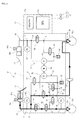
- the motorcycle 1 includes a body frame 10.
- a head pipe (not shown) is formed on a front end portion of the body frame 10.
- a steering shaft (not shown) is rotatably inserted into the head pipe.
- a pair of left and right front forks 14 are mounted on the steering shaft.
- a front wheel 15 is rotatably supported at lower end portions of the pair of left and right front forks 14.
- a steering handle bar 12 is mounted on the head pipe.
- a pivot shaft (not shown) is mounted on a rear end portion of the body frame 10.
- a rear arm 16 is swingably mounted on the pivot shaft.
- a rear wheel 17 is rotatably supported by a rear end portion of the rear arm 16. The rear wheel 17 is driven by an engine 20 which is suspended by the body frame 10.
- the motorcycle 1 is provided with a braking system 30.
- the braking system 30 is for decelerating the motorcycle 1.
- the braking system 30 of the embodiment includes a front wheel-side braking mechanism which applies a brake to the front wheel 15, a rear wheel-side braking mechanism which applies a brake to the rear wheel 17, a front association mechanism, a rear association mechanism, and an ABS mechanism.
- the front association mechanism refers to a mechanism which drives the rear wheel-side braking mechanism when the front wheel-side braking mechanism is operated.
- the rear association mechanism refers to a mechanism which drives the front wheel-side braking mechanism when the rear wheel-side braking mechanism is operated.
- Most mechanisms of the braking system 30 are accommodated in an HU (Hydraulic Unit) 31.
- the braking system 30 includes a first braking force generating mechanism 35 and a second braking force generating mechanism 36.
- the first braking force generating mechanism 35 is provided to the rear wheel 17.
- the first braking force generating mechanism 35 is supplied with hydraulic pressure, thereby generating a braking force for the rear wheel 17. More specifically, the first braking force generating mechanism 35 includes a first caliper 35a and a first brake disk 35b. The first brake disk 35b rotates together with the rear wheel 17.
- the second braking force generating mechanism 36 is provided to the front wheel 15.
- the second braking force generating mechanism 36 is supplied with hydraulic pressure, thereby generating a braking force for the front wheel 15.
- the second braking force generating mechanism 36 includes a second caliper 36a and a second brake disk 36b. More specifically, the second brake disk 36b rotates together with the front wheel 15.
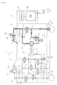
- the first braking force generating mechanism 35 is connected to a first master cylinder 40a through a first brake fluid passage 42.
- a reservoir tank 41a and a brake pedal 18 as a first operation member are connected to the first master cylinder 40a. If a rider operates the brake pedal 18, hydraulic pressure is supplied from the first master cylinder 40a to the first braking force generating mechanism 35.
- the brake pedal 18 is provided with a stroke sensor 18a. An operation amount of the brake pedal 18 is detected also by the stroke sensor 18a. The detected operation amount of the brake pedal 18 is output to a CPU 28a.
- a second hydraulic pressure sensor 43 as the first hydraulic pressure detection section is connected to a point A of the first brake fluid passage 42.
- the second hydraulic pressure sensor 43 detects hydraulic pressure at the point A of the first brake fluid passage 42.
- a first on-off valve 44 and a third on-off valve 45 are disposed in the first brake fluid passage 42.
- the first on-off valve 44 is disposed between a point B and a point C of the first brake fluid passage 42.
- the first on-off valve 44 is an open-when-nonenergized type on-off valve which opens when electric power is not supplied, and which closes when electric power is supplied.
- the third on-off valve 45 is disposed between the point C and a point D of the first brake fluid passage 42.
- the third on-off valve 45 is also an open-when-nonenergized type on-off valve like the first on-off valve 44.
- the first on-off valve 44, the third brake fluid passage 47, the first brake fluid pump 49 and the second on-off valve 57 constitute the front association mechanism 21.
- a third hydraulic pressure sensor 46 as the second hydraulic pressure detection section is connected to a point E of the first brake fluid passage 42.
- the third hydraulic pressure sensor 46 has a higher hydraulic pressure detection accuracy than the second hydraulic pressure sensor 43.
- the second hydraulic pressure sensor 43 is more excellent in terms of the resistance to pressure than the third hydraulic pressure sensor 46.
- the point B of the first brake fluid passage 42 closer to the first master cylinder 40a and the point C closer to the first braking force generating mechanism 35 than a portion of the first brake fluid passage 42 where the first on-off valve 44 is disposed are connected to each other through a third brake fluid passage 47.
- the third brake fluid passage 47 extends from the point B to the point C through a point F and a point H.
- An brake fluid pump 49 is disposed in the third brake fluid passage 47.
- the brake fluid pump 49 is connected to a motor 50.
- the brake fluid pump 49 is activated when the motor 50 is driven by a later-described ECU 28. If the brake fluid pump 49 is activated, pressure on the side of the point B becomes low pressure and the pressure on the side of the point C becomes high pressure.
- a second on-off valve 57 is disposed in the third brake fluid passage 47. More specifically, the second on-off valve 57 is disposed closer to the point B than the brake fluid pump 49 of the third brake fluid passage 47.
- the second on-off valve 57 is a closed-when-nonenergized type on-off valve which closes when electric power is not supplied and which opens when electric power is supplied.
- a buffer chamber 58 is connected to the point H of the third brake fluid passage 47.
- the point F which is located closer to the point B than the second on-off valve 57, is connected to the second caliper 36a through a fourth brake fluid passage 51. That is, the first brake fluid passage 51 connects the first master cylinder 40a and the second braking force generating mechanism 36 with each other without using the second brake fluid passage 60.
- a fifth on-off valve 52 is disposed between the point F and a point G of the fourth brake fluid passage 51.
- the fifth on-off valve 52 is an open-when-nonenergized type on-off valve.
- a metering valve 53 is disposed between the point G of the fourth brake fluid passage 51 and the second caliper 36a.
- the point D of the first brake fluid passage 42 and the point H of the third brake fluid passage 47 are connected to each other through a fifth brake fluid passage 56.
- a fourth on-off valve 48 is disposed in the fifth brake fluid passage 56.
- the fourth on-off valve 48 is a closed-when-nonenergized type on-off valve.
- the point G of the fourth brake fluid passage 51 and a point I of the fifth brake fluid passage 56 are connected to each other through a sixth brake fluid passage 54.
- a sixth on-off valve 55 is disposed in the sixth brake fluid passage 54.
- the sixth on-off valve 55 is a closed-when-nonenergized type on-off valve.
- the second braking force generating mechanism 36 is connected to a second master cylinder 40b through a second brake fluid passage 60.
- a reservoir tank 41b and a brake lever 13 as a second operation member are connected to the second master cylinder 40b. If a rider operates the brake lever 13, hydraulic pressure is supplied from the second master cylinder 40b to the second braking force generating mechanism 36.
- a stroke sensor 13a is provided to the brake lever 13. The operation amount of the brake lever 13 is detected also by the stroke sensor 13a. The detected operation amount of the brake lever 13 is output to the CPU 28a.
- a first hydraulic pressure sensor 61 as an operation amount detection section is connected to a point J of the second brake fluid passage 60.
- the first hydraulic pressure sensor 61 detects hydraulic pressure at the point J of the second brake fluid passage 60. With this, the operation amount of the brake lever 13 as the second operation member is indirectly detected.
- the first hydraulic pressure sensor 61 detects both the hydraulic pressure in the second brake fluid passage 60 and the operation of the brake lever 13. Therefore, as compared with a case where a special-purpose sensor for detecting the operation of the brake lever 13 is provided, the number of parts can be reduced and the structure can be simplified.
- a sensor which directly detects the operation amount of the brake lever 13 may be disposed instead of the first hydraulic pressure sensor 61, or together with the first hydraulic pressure sensor 61.
- An example of the sensor which directly detects the operation amount of the brake lever 13 includes a position sensor which detects a position of the brake lever 13.
- a seventh on-off valve 62 is disposed in a portion closer to the second braking force generating mechanism 36 than the point J of the second brake fluid passage 60.
- the seventh on-off valve 62 is an open-when-nonenergized type on-off valve.
- a point K of the second brake fluid passage 60 closer to the second master cylinder 40b and a point L of the second brake fluid passage 60 closer to the second braking force generating mechanism 36 than the seventh on-off valve 62 are connected to each other through a seventh brake fluid passage 63.
- a second brake fluid pump 64 is disposed in the seventh brake fluid passage 63.
- the second brake fluid pump 64 is driven by the motor 50 mentioned above. If the second brake fluid pump 64 is driven, the pressure on the side of the point L becomes low pressure and the pressure on the side of the point K becomes high pressure.
- the motor 50 in a state where a power source of the motorcycle 1 is ON, the motor 50 is always driven, and the first and the second brake fluid pumps 49 and 64 are always activated.
- An eighth on-off valve 65 is disposed between the second brake fluid pump 64 and the point L.
- the eighth on-off valve 65 is a closed-when-nonenergized type on-off valve.
- a buffer chamber 66 is connected to a connection point between the eighth on-off valve 65 and the second brake fluid pump 64.
- the ECU (Electronic Control Unit) 28 as a control unit is disposed adjacent to the HU 31 .
- the ECU 28 is used only for controlling the HU 31.
- An ECU (not shown) used for controlling the engine 20 shown in Fig. 1 is provided independently from the ECU 28.
- the present invention is not limited to this configuration.
- one ECU 28 may control both the engine 20 and the HU 31.
- the ECU 28 includes the CPU 28a as a calculating section and a memory 28b as a storing section connected to the CPU 28a.
- Various settings are stored in the memory 28b as will be described in detail later.
- Various detection values are also stored in the memory 28b.
- the CPU 28a is connected to the on-off valves, the hydraulic pressure sensors and the motor 50 which are included in the HU 31.
- the on-off valves and the motor 50 included in the HU 31 are controlled by the CPU 28a. Hydraulic pressures detected by the hydraulic pressure sensors 43, 46 and 61 are sent to the CPU 28a.
- a front wheel rotation speed sensor 27a and a rear wheel rotation speed sensor 27b are connected to the CPU 28a.
- a rotation speed of the front wheel 15 is detected by the front wheel rotation speed sensor 27a and is output to the CPU 28a.
- a rotation speed of the rear wheel 17 is detected by the rear wheel rotation speed sensor 27b and is output to the CPU 28a.
- the CPU 28a calculates a vehicle speed which is a speed of the motorcycle 1 based on output from the front wheel rotation speed sensor 27a and the rear wheel rotation speed sensor 27b. That is, in this embodiment, the front wheel rotation speed sensor 27a and the rear wheel rotation speed sensor 27b constitute a vehicle speed sensor 27.
- a method for calculating a vehicle speed from the front wheel rotation speed and the rear wheel rotation speed is not especially limited.
- an average value of the front wheel rotation speed and the rear wheel rotation speed may be defined as the vehicle speed.
- the vehicle speed sensor 27 constituted by the front wheel rotation speed sensor 27a and the rear wheel rotation speed sensor 27b above constitutes the locked state detection section.
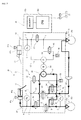
- Fig , 4 is a schematic structure diagram of the braking system when the brake lever 13 is operated.
- hydraulic pressure is supplied from the second master cylinder 40b.
- the seventh on-off valve 62 is the open-when-nonenergized type on-off valve. Therefore, the hydraulic pressure from the second master cylinder 40b is supplied to the second caliper 36a through the second brake fluid passage 60. With this, a braking force is generated in the second braking force generating mechanism 36 which is provided to the front wheel 15.
- the brake lever 13 If the brake lever 13 is operated, the increase of the hydraulic pressure in the second brake fluid passage 60 is detected by the first hydraulic pressure sensor 61, and this fact is output to the ECU 28.
- the ECU 28 determines whether or not the brake lever 13 is operated based on the hydraulic pressure in the second brake fluid passage 60.
- the ECU 28 determines that the brake lever 13 is operated, the ECU 28 closes the first on-off valve 44 and opens the second on-off valve 57.
- brake fluid in the first master cylinder 40a is sucked by the first brake fluid pump 49, and the brake fluid is supplied to the first caliper 35a through the third brake fluid passage 47 and the first brake fluid passage 42.
- a braking force is generated in the first braking force generating mechanism 35 which is provided to the rear wheel 17.
- a braking force is generated in the second braking force generating mechanism 36 and a braking force is generated also in the first braking force generating mechanism 35.
- This associationed operation is realized through the ECU 28. For this reason, this front associationed operation is called an electrically associationed operation.
- Fig. 5 is a schematic structure diagram of the braking system when the brake pedal 18 is operated.
- brake fluid is discharged from the first master cylinder 40a.
- the first on-off valve 44 and the third on-off valve 45 are open-when-nonenergized type on-off valves. Therefore, the brake fluid discharged from the first master cylinder 40a is supplied to the first caliper 35a through the first brake fluid passage 42. With this, a braking force is generated in the first braking force generating mechanism 35 which is provided to the rear wheel 17.
- the fifth on-off valve 52 is also the open-when-nonenergized type on-off valve. Therefore, brake fluid discharged from the first master cylinder 40a is supplied also to the second caliper 36a through the fourth brake fluid passage 51. With this, a braking force is generated in the second braking force generating mechanism 36 which is provided to the front wheel 15.
- a braking force is generated not only in the first braking force generating mechanism 35 but also in the second braking force generating mechanism 36.
- This associationed operation is different from the associationed operation caused when the brake lever 13 is operated and is mechanically performed without using the ECU 28.
- this rear associationed operation is called a mechanically associationed operation.
- Fig. 6 is a schematic structure diagram of the braking system for describing the ABS action of the second braking force generating mechanism 36 when the brake lever 13 is operated.
- the ECU 28 detects a locked state of the front wheel 15 based on output from the front wheel rotation speed sensor 27a and output from the rear wheel rotation speed sensor 27b. More specifically, the ECU 28 detects the locked state of the front wheel 15 when the magnitude of the front wheel rotation speed is largely reduced with respect to the vehicle speed.
- the ECU 28 If the ECU 28 detects the locked state of the front wheel 15, the ECU 28 supplies current to the seventh and the eighth on-off valves 62 and 65. With this, the seventh on-off valve 62 is closed and the eighth on-off valve 65 is opened. Therefore, brake fluid is sent from the second caliper 36a to the second master cylinder 40b through the seventh brake fluid passage 63. As a result, a braking force generated in the second braking force generating mechanism 36 is reduced.
- the ECU 28 If the ECU 28 detects that the locked state of the front wheel 15 is released, the ECU 28 stops the current supply to the seventh and the eighth on-off valves 62 and 65. With this, the seventh on-off valve 62 is opened and the eighth on-off valve 65 is closed. As a result, a braking force generated in the second braking force generating mechanism 36 is again increased.
- Fig. 7 is a schematic structure diagram of the braking system for describing the ABS action of the first and the second braking force generating mechanisms 35 and 36 when the brake pedal 18 is operated.
- the ECU 28 detects the locked state of the rear wheel 17 based on output from the front wheel rotation speed sensor 27a and output from the rear wheel rotation speed sensor 27b, More specifically, the ECU 28 detects the locked state of the rear wheel 17 when the level of the rear wheel rotation speed is largely reduced with respect to the vehicle speed.
- the ECU 28 If the ECU 28 detects the locked state of the rear wheel 17, the ECU 28 supplies current to the third on-off valve 45 and the fourth on-off valve 48. With this, the third on-off valve 45 is closed and the fourth on-off valve 48 is opened. Therefore, the brake fluid in the first caliper 35a is sent to the first master cylinder 40a through the third brake fluid passage 47. As a result, a braking force generated in the first braking force generating mechanism 35 is reduced.
- the ECU 28 If the ECU 28 detects that the locked state of the rear wheel 17 is released, the ECU 28 stops the current supply to the third and the fourth on-off valves 45 and 48. With this, the third on-off valve 45 is opened and the fourth on-off valve 48 is closed. As a result, a braking force generated in the first braking force generating mechanism 35 is again increased.
- the third and the fourth on-off valves 45 and 48, a portion of the third brake fluid passage 47, the fifth brake fluid passage 56 and the first brake fluid pump 49 constitute the ABS mechanism 99 on the side of the rear wheel 17.
- the ECU 28 If the ECU 28 detects the locked state of the front wheel 15, the ECU 28 supplies current to the fifth on-off valve 52 and the sixth on-off valve 55 as shown in Fig. 7 . With this, the fifth on-off valve 52 is closed and the sixth on-off valve 55 is opened. Thus, brake fluid in the second caliper 36a is sent to the second master cylinder 40b through the sixth brake fluid passage 54. As a result, a braking force generated in the second braking force generating mechanism 36 is reduced.
- the ECU 28 If the ECU 28 detects that the locked state of the front wheel 15 is released, the ECU 28 stops the current supply to the fifth and the sixth on-off valves 52 and 55. With this, the fifth on-off valve 52 is opened and the sixth on-off valve 55 is closed. As a result, a braking force generated in the second braking force generating mechanism 36 is again increased.
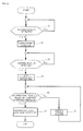
- step S1 the ECU 28 determines whether or not the brake lever 13 is operated based on hydraulic pressure detected by the first hydraulic pressure sensor 61 as the operation amount detection section shown in Fig. 3 . In more detail, when the hydraulic pressure detected by the first hydraulic pressure sensor 61 is smaller than a predetermined hydraulic pressure, the ECU 28 determines that the brake lever 13 is not operated. In this case, step S1 is again executed.
- the ECU 28 determines that the brake lever 13 is operated. In this case, the procedure is advanced to step S2.
- the ECU 28 carries out a front associationed control.
- the front associationed control means a control for supplying hydraulic pressure of a magnitude corresponding to the operation amount of the brake lever 13 also to the first braking force generating mechanism 35 when the brake lever 13 as the second operation member is operated. More specifically, the ECU 28 closes the first on-off valve 44 and opens the second on-off valve 57. With this, brake fluid in the first master cylinder 40a is sucked by the first brake fluid pump 49, and is then supplied to the first braking force generating mechanism 35. As a result, hydraulic pressure is supplied to the first braking force generating mechanism 35.
- the ECU 28 controls the magnitude of the hydraulic pressure supplied to the first braking force generating mechanism 35 to a magnitude corresponding to the operation amount of the brake lever 13 by adjusting the opening of the second on-off valve 57 in accordance with the operation amount of the brake lever 13.
- the ECU 28 as the control unit detects hydraulic pressure supplied to the first braking force generating mechanism 35 by the third hydraulic pressure sensor 46.
- the ECU 28 detects the operation of the brake pedal 18 by the second hydraulic pressure sensor 43.
- the third hydraulic pressure sensor 46 having high detection accuracy detects hydraulic pressure supplied to the first braking force generating mechanism 35, and also detects the operation of the brake pedal 18.
- step S3 is executed.
- the ECU 28 determines whether or not the brake pedal 18 is operated based on hydraulic pressure detected by the second hydraulic pressure sensor 43. More specifically, when hydraulic pressure detected by the second hydraulic pressure sensor 43 is smaller than the predetermined hydraulic pressure, the ECU 28 determines that the brake pedal 18 is not operated. In this case, step S3 is again executed.
- step S4 is executed after step S3.
- step S4 the ECU 28 stops a associationed pressurizing operation. With this, hydraulic pressure supplied to the first braking force generating mechanism 35 is not varied even if the operation amount of the brake lever 13 is varied after step S4.
- step S5 is executed.
- the ECU 28 determines whether or not hydraulic pressure (operation hydraulic pressure) of a magnitude corresponding to the operation amount of the brake pedal 18 detected by the second hydraulic pressure sensor 43 is equal to or higher than the current hydraulic pressure supplied to the first braking force generating mechanism 35.
- step S6 When it is determined in step S5 that the operation hydraulic pressure is equal to or higher than the current hydraulic pressure, the procedure is advanced to step S6.
- step S6 the ECU 28 opens the first on-off valve 44 and closes the second on-off valve 57. With this, the supply of hydraulic pressure to the first braking force generating mechanism 35 by the association mechanism 21 is stopped, and the hydraulic pressure is supplied to the first braking force generating mechanism 35 by the operation of the brake pedal 18.
- hydraulic pressure of a magnitude corresponding to the operation amount of the brake pedal 18 is supplied to the first braking force generating mechanism 35. Therefore, a braking force of a magnitude suitable for a rider's intention is generated in the first braking force generating mechanism 35. Therefore, the rider is less prone to be bothered by a feeling of incongruity.
- step S5 when it is determined in step S5 that the operation hydraulic pressure is smaller than the current hydraulic pressure, the procedure is advanced to step S7.
- step S7 the ECU 28 closes the first on-off valve 44 and opens the second on-off valve 57 and in this state, maintains the current hydraulic pressure. If step S7 is completed, the procedure is returned to step S5.
- the current hydraulic pressure is maintained until the operation hydraulic pressure corresponding to the operation amount of the brake pedal 18 becomes equal to or higher than the current hydraulic pressure.
- the current hydraulic pressure is maintained until the operation hydraulic pressure corresponding to the operation amount of the brake pedal 18 becomes equal to or higher than the current hydraulic pressure as described above. Therefore, it is possible to suppress abrupt variation in braking force generated in the first braking force generating mechanism 35.
- the hydraulic pressure supplied from the first master cylinder 40a becomes extremely high.
- the operation member connected to the first master cylinder 40a is the brake pedal 18 which is operated by foot as in this embodiment, high hydraulic pressure is prone to be applied to the second hydraulic pressure sensor 43 as compared with a case where the brake lever operated by hand. Therefore, high resistance to pressure is required for the second hydraulic pressure sensor 43. Therefore, it is preferable that the second hydraulic pressure sensor 43 has high resistance to pressure.
- the ABS mechanism 99 when the ABS mechanism 99 is provided as in this embodiment, hydraulic pressure applied to the second hydraulic pressure sensor 43 when the ABS mechanism 99 is driven becomes extremely high. Therefore, it is especially preferable that the second hydraulic pressure sensor 43 has high resistance to pressure.
- the resistance to pressure of the hydraulic pressure sensor and the detection accuracy are in the trade off relation. That is, it is not possible to expect high detection accuracy from a hydraulic pressure sensor having high resistance to pressure. There is a tendency that a hydraulic pressure sensor having high detection accuracy has low resistance to pressure. Thus, when a second hydraulic pressure sensor 43 constituted by a hydraulic pressure sensor having high resistance to pressure is provided, it becomes difficult to detect the operation amount of the brake pedal 18 highly accurately.
- two hydraulic pressure sensors are provided, i.e., the second hydraulic pressure sensor 43 which detects hydraulic pressure at the point A closer to the first master cylinder 40a than the point B of the first brake fluid passage 42, and the third hydraulic pressure sensor 46 which detects hydraulic pressure at the point E closer to the first master cylinder 40a than the point D of the first brake fluid passage 42.
- the third hydraulic pressure sensor 46 having high detection accuracy detects hydraulic pressure supplied to the first braking force generating mechanism 35. Therefore, when the associationed control is not executed, it is possible to highly accurately detect hydraulic pressure supplied to the first braking force generating mechanism 35. It is also possible to highly accurately detect the operation amount of the brake pedal 18.
- the ECU 28 detects the operation of the brake pedal 18 by the second hydraulic pressure sensor 43.
- the ECU 28 detects the operation of the brake pedal 18 during the associationed control.
- hydraulic pressure of the first master cylinder 40a is finely varied in some cases depending upon the associationed control. Therefore, a hydraulic pressure value detected by the second hydraulic pressure sensor 43 is finely varied in some cases. An influence of the very small variation of a detected value resulting from the associationed control is eliminated and then, only large variation in hydraulic pressure caused as a result of a rider's operation of the brake pedal 18 should be detected. Accordingly, so much high detection accuracy is not required for the second hydraulic pressure sensor 43. In other words, there is no problem even if the second hydraulic pressure sensor 43 has low detection accuracy.
- the second hydraulic pressure sensor 43 Since the second hydraulic pressure sensor 43 has high resistance to pressure, the second hydraulic pressure sensor 43 is less prone to be damaged even if the brake pedal 18 is operated during the associationed control and high hydraulic pressure is applied to the second hydraulic pressure sensor 43.
- the second hydraulic pressure sensor 43 has lower detection accuracy than the third hydraulic pressure sensor 46. Therefore, during the associationed control, the detection accuracy of the operation amount of the brake pedal 18 becomes low. According to this embodiment, however, the first master cylinder 40a and the second braking force generating mechanism 36 are connected to each other through the fourth brake fluid passage 51. Therefore, the brake fluid of the first master cylinder 40a is supplied also to the second braking force generating mechanism 36 without using the electronic control. Thus, during the associationed control, requirement of detection accuracy of the operation amount of the brake pedal 18 is relatively low. Therefore, there is not a very serious problem even if the detection accuracy of the operation amount of the brake pedal 18 is lowered.
- the fourth brake fluid passage 51 connects the first master cylinder 40a and the second braking force generating mechanism 36 with each other without using the second brake fluid passage 60. That is, an brake fluid passage from the first master cylinder 40a to the second braking force generating mechanism 36 and an brake fluid passage from the second master cylinder 40b to the second braking force generating mechanism 36 are separated from each other.
- the first hydraulic pressure sensor 61 is not required to have so much high resistance to pressure. Therefore, the first hydraulic pressure sensor 61 can have high detection accuracy. Therefore, it is possible to highly accurately measure the operation amount of the brake lever 13 and hydraulic pressure supplied to the second braking force generating mechanism 36.
- a magnitude of hydraulic pressure supplied to the first braking force generating mechanism 35 is adjusted by adjusting the opening of the second on-off valve 57. For this reason, it is possible to more swiftly and more correctly adjust hydraulic pressure than a case where the magnitude of hydraulic pressure supplied to the first braking force generating mechanism 35 is adjusted by adjusting output of the first brake fluid pump 49, for example.
- the first on-off valve 44 is an open-when-nonenergized type on-off valve
- the second on-off valve 57 is a closed-when-nonenergized type on-off valve.
- Fig. 9 is a schematic structure diagram showing a structure of a braking system according to this modification. As shown in Fig. 9 , the braking system may not be provided with the rear association mechanism. More specifically, in this modification, the fourth brake fluid passage 51, the metering valve 53, the fifth on-off valve 52, the sixth brake fluid passage 54 and the sixth on-off valve 55 are not provided.
Priority Applications (1)
| Application Number | Priority Date | Filing Date | Title |
|---|---|---|---|
| EP20090173233 EP2311699B1 (de) | 2009-10-16 | 2009-10-16 | Bremssystem für ein Motorrad |
Applications Claiming Priority (1)
| Application Number | Priority Date | Filing Date | Title |
|---|---|---|---|
| EP20090173233 EP2311699B1 (de) | 2009-10-16 | 2009-10-16 | Bremssystem für ein Motorrad |
Publications (2)
| Publication Number | Publication Date |
|---|---|
| EP2311699A1 true EP2311699A1 (de) | 2011-04-20 |
| EP2311699B1 EP2311699B1 (de) | 2013-09-04 |
Family
ID=41665510
Family Applications (1)
| Application Number | Title | Priority Date | Filing Date |
|---|---|---|---|
| EP20090173233 Active EP2311699B1 (de) | 2009-10-16 | 2009-10-16 | Bremssystem für ein Motorrad |
Country Status (1)
| Country | Link |
|---|---|
| EP (1) | EP2311699B1 (de) |
Cited By (2)
| Publication number | Priority date | Publication date | Assignee | Title |
|---|---|---|---|---|
| EP2565090A1 (de) * | 2011-08-27 | 2013-03-06 | Honda Motor Co., Ltd. | Motorrad mit vor dem Rahmenvorderrohr dessen Motorrads angebrachtem ABS-Aggregat |
| WO2022038620A1 (en) * | 2020-08-19 | 2022-02-24 | Tvs Motor Company Limited | A braking system for a motor vehicle |
Citations (7)
| Publication number | Priority date | Publication date | Assignee | Title |
|---|---|---|---|---|
| JP2000006779A (ja) | 1998-06-19 | 2000-01-11 | Yamaha Motor Co Ltd | 鞍乗型車両の制動装置 |
| EP1277635A2 (de) * | 2001-07-19 | 2003-01-22 | BOSCH BRAKING SYSTEMS Co., Ltd. | Bremssteuerverfahren und Vorrichtung für Motorräder |
| WO2006040261A1 (de) * | 2004-10-07 | 2006-04-20 | Continental Teves Ag & Co. Ohg | Kraftradbremsanlage |
| US20060082216A1 (en) * | 2004-10-20 | 2006-04-20 | Markus Hamm | Integral brake for a motorbike |
| EP1671863A2 (de) * | 2004-12-16 | 2006-06-21 | HONDA MOTOR CO., Ltd. | Elektronisches Bremssystem |
| WO2008090783A1 (ja) * | 2007-01-26 | 2008-07-31 | Bosch Corporation | 自動二輪車のブレーキ制御装置 |
| EP2042396A1 (de) * | 2007-09-25 | 2009-04-01 | HONDA MOTOR CO., Ltd. | Bremssystem |
-
2009
- 2009-10-16 EP EP20090173233 patent/EP2311699B1/de active Active
Patent Citations (8)
| Publication number | Priority date | Publication date | Assignee | Title |
|---|---|---|---|---|
| JP2000006779A (ja) | 1998-06-19 | 2000-01-11 | Yamaha Motor Co Ltd | 鞍乗型車両の制動装置 |
| EP1277635A2 (de) * | 2001-07-19 | 2003-01-22 | BOSCH BRAKING SYSTEMS Co., Ltd. | Bremssteuerverfahren und Vorrichtung für Motorräder |
| WO2006040261A1 (de) * | 2004-10-07 | 2006-04-20 | Continental Teves Ag & Co. Ohg | Kraftradbremsanlage |
| US20060082216A1 (en) * | 2004-10-20 | 2006-04-20 | Markus Hamm | Integral brake for a motorbike |
| EP1671863A2 (de) * | 2004-12-16 | 2006-06-21 | HONDA MOTOR CO., Ltd. | Elektronisches Bremssystem |
| WO2008090783A1 (ja) * | 2007-01-26 | 2008-07-31 | Bosch Corporation | 自動二輪車のブレーキ制御装置 |
| EP2116436A1 (de) * | 2007-01-26 | 2009-11-11 | Bosch Corporation | Bremssteuerungsvorrichtung für ein zweirädriges motorfahrzeug |
| EP2042396A1 (de) * | 2007-09-25 | 2009-04-01 | HONDA MOTOR CO., Ltd. | Bremssystem |
Cited By (2)
| Publication number | Priority date | Publication date | Assignee | Title |
|---|---|---|---|---|
| EP2565090A1 (de) * | 2011-08-27 | 2013-03-06 | Honda Motor Co., Ltd. | Motorrad mit vor dem Rahmenvorderrohr dessen Motorrads angebrachtem ABS-Aggregat |
| WO2022038620A1 (en) * | 2020-08-19 | 2022-02-24 | Tvs Motor Company Limited | A braking system for a motor vehicle |
Also Published As
| Publication number | Publication date |
|---|---|
| EP2311699B1 (de) | 2013-09-04 |
Similar Documents
| Publication | Publication Date | Title |
|---|---|---|
| JP4832460B2 (ja) | ブレーキ装置 | |
| US8046149B2 (en) | Brake apparatus for vehicle, and methods of using same | |
| JP5122653B2 (ja) | 自動二輪車用ブレーキ装置 | |
| US10899329B2 (en) | Hydraulic brake system, bicycle, and method for controlling hydraulic brake system | |
| CN112512878B (zh) | 制动液压控制装置、跨乘型车辆及制动液压控制方法 | |
| US20070252429A1 (en) | Motorcycle Brake System | |
| EP2311704B1 (de) | Bremssystem für ein Motorrad | |
| JP7142465B2 (ja) | 液圧制御ユニット | |
| JP5006051B2 (ja) | モーターサイクルブレーキシステム | |
| JP6692313B2 (ja) | バーハンドル車両用ブレーキ制御装置 | |
| JP2009154799A (ja) | 制動装置及び該制動装置を備えた鞍乗型車両 | |
| EP2311699B1 (de) | Bremssystem für ein Motorrad | |
| EP2075169B1 (de) | Bremsvorrichtung und damit versehenes Grätschsitz-Fahrzeug | |
| US11572049B2 (en) | Brake control device | |
| EP2647534B1 (de) | Bremssystem für ein Motorrad | |
| JP4874172B2 (ja) | 二輪車用ブレーキ制御装置 | |
| EP2586669B1 (de) | Bremssystem für ein Motorrad | |
| KR101350844B1 (ko) | 브레이크 페달 스트로크 센서의 오프셋 보정 장치 및 그 방법 | |
| EP2311701A1 (de) | Bremssystem für ein Motorrad | |
| EP2311702B1 (de) | Bremssystem für ein Motorrad | |
| EP2311703B1 (de) | Bremssystem für ein Motorrad | |
| JP7367427B2 (ja) | 車両の制動装置 | |
| JPWO2005039947A1 (ja) | アンチロック・ブレーキ制御装置、該アンチロック・ブレーキ制御装置を備えたアンチロック・ブレーキ・システム | |
| JP2006175905A (ja) | 車両のブレーキ液圧制御装置 | |
| JP5281092B2 (ja) | Absを備える自動二輪車用の連動式ブレーキ制御装置及びその制御方法 |
Legal Events
| Date | Code | Title | Description |
|---|---|---|---|
| PUAI | Public reference made under article 153(3) epc to a published international application that has entered the european phase |
Free format text: ORIGINAL CODE: 0009012 |
|
| AK | Designated contracting states |
Kind code of ref document: A1 Designated state(s): AT BE BG CH CY CZ DE DK EE ES FI FR GB GR HR HU IE IS IT LI LT LU LV MC MK MT NL NO PL PT RO SE SI SK SM TR |
|
| AX | Request for extension of the european patent |
Extension state: AL BA RS |
|
| 17P | Request for examination filed |
Effective date: 20111005 |
|
| 17Q | First examination report despatched |
Effective date: 20120410 |
|
| GRAP | Despatch of communication of intention to grant a patent |
Free format text: ORIGINAL CODE: EPIDOSNIGR1 |
|
| RIC1 | Information provided on ipc code assigned before grant |
Ipc: B62L 3/08 20060101ALN20130220BHEP Ipc: B60T 8/26 20060101AFI20130220BHEP Ipc: B60T 8/32 20060101ALI20130220BHEP |
|
| RIC1 | Information provided on ipc code assigned before grant |
Ipc: B62L 3/08 20060101ALN20130228BHEP Ipc: B60T 8/32 20060101ALI20130228BHEP Ipc: B60T 8/26 20060101AFI20130228BHEP |
|
| RIN1 | Information on inventor provided before grant (corrected) |
Inventor name: KAJIWARA, KUNIO Inventor name: KUSANO, TAISHI Inventor name: MEIXNER, MICHAEL Inventor name: WATANABE, TAKAHIRO Inventor name: UCHIDA, TAKANORI Inventor name: KREMER, MICHAEL |
|
| GRAS | Grant fee paid |
Free format text: ORIGINAL CODE: EPIDOSNIGR3 |
|
| GRAA | (expected) grant |
Free format text: ORIGINAL CODE: 0009210 |
|
| AK | Designated contracting states |
Kind code of ref document: B1 Designated state(s): AT BE BG CH CY CZ DE DK EE ES FI FR GB GR HR HU IE IS IT LI LT LU LV MC MK MT NL NO PL PT RO SE SI SK SM TR |
|
| REG | Reference to a national code |
Ref country code: GB Ref legal event code: FG4D |
|
| REG | Reference to a national code |
Ref country code: CH Ref legal event code: EP |
|
| REG | Reference to a national code |
Ref country code: AT Ref legal event code: REF Ref document number: 630307 Country of ref document: AT Kind code of ref document: T Effective date: 20130915 |
|
| REG | Reference to a national code |
Ref country code: IE Ref legal event code: FG4D |
|
| REG | Reference to a national code |
Ref country code: DE Ref legal event code: R096 Ref document number: 602009018495 Country of ref document: DE Effective date: 20131031 |
|
| REG | Reference to a national code |
Ref country code: AT Ref legal event code: MK05 Ref document number: 630307 Country of ref document: AT Kind code of ref document: T Effective date: 20130904 |
|
| REG | Reference to a national code |
Ref country code: NL Ref legal event code: VDEP Effective date: 20130904 |
|
| PG25 | Lapsed in a contracting state [announced via postgrant information from national office to epo] |
Ref country code: AT Free format text: LAPSE BECAUSE OF FAILURE TO SUBMIT A TRANSLATION OF THE DESCRIPTION OR TO PAY THE FEE WITHIN THE PRESCRIBED TIME-LIMIT Effective date: 20130904 Ref country code: LT Free format text: LAPSE BECAUSE OF FAILURE TO SUBMIT A TRANSLATION OF THE DESCRIPTION OR TO PAY THE FEE WITHIN THE PRESCRIBED TIME-LIMIT Effective date: 20130904 Ref country code: NO Free format text: LAPSE BECAUSE OF FAILURE TO SUBMIT A TRANSLATION OF THE DESCRIPTION OR TO PAY THE FEE WITHIN THE PRESCRIBED TIME-LIMIT Effective date: 20131204 Ref country code: SE Free format text: LAPSE BECAUSE OF FAILURE TO SUBMIT A TRANSLATION OF THE DESCRIPTION OR TO PAY THE FEE WITHIN THE PRESCRIBED TIME-LIMIT Effective date: 20130904 Ref country code: HR Free format text: LAPSE BECAUSE OF FAILURE TO SUBMIT A TRANSLATION OF THE DESCRIPTION OR TO PAY THE FEE WITHIN THE PRESCRIBED TIME-LIMIT Effective date: 20130904 Ref country code: CY Free format text: LAPSE BECAUSE OF FAILURE TO SUBMIT A TRANSLATION OF THE DESCRIPTION OR TO PAY THE FEE WITHIN THE PRESCRIBED TIME-LIMIT Effective date: 20130717 |
|
| REG | Reference to a national code |
Ref country code: NL Ref legal event code: VDEP Effective date: 20130904 |
|
| REG | Reference to a national code |
Ref country code: LT Ref legal event code: MG4D |
|
| PG25 | Lapsed in a contracting state [announced via postgrant information from national office to epo] |
Ref country code: GR Free format text: LAPSE BECAUSE OF FAILURE TO SUBMIT A TRANSLATION OF THE DESCRIPTION OR TO PAY THE FEE WITHIN THE PRESCRIBED TIME-LIMIT Effective date: 20131205 Ref country code: FI Free format text: LAPSE BECAUSE OF FAILURE TO SUBMIT A TRANSLATION OF THE DESCRIPTION OR TO PAY THE FEE WITHIN THE PRESCRIBED TIME-LIMIT Effective date: 20130904 Ref country code: SI Free format text: LAPSE BECAUSE OF FAILURE TO SUBMIT A TRANSLATION OF THE DESCRIPTION OR TO PAY THE FEE WITHIN THE PRESCRIBED TIME-LIMIT Effective date: 20130904 Ref country code: LV Free format text: LAPSE BECAUSE OF FAILURE TO SUBMIT A TRANSLATION OF THE DESCRIPTION OR TO PAY THE FEE WITHIN THE PRESCRIBED TIME-LIMIT Effective date: 20130904 Ref country code: PL Free format text: LAPSE BECAUSE OF FAILURE TO SUBMIT A TRANSLATION OF THE DESCRIPTION OR TO PAY THE FEE WITHIN THE PRESCRIBED TIME-LIMIT Effective date: 20130904 |
|
| PG25 | Lapsed in a contracting state [announced via postgrant information from national office to epo] |
Ref country code: CY Free format text: LAPSE BECAUSE OF FAILURE TO SUBMIT A TRANSLATION OF THE DESCRIPTION OR TO PAY THE FEE WITHIN THE PRESCRIBED TIME-LIMIT Effective date: 20130904 Ref country code: BE Free format text: LAPSE BECAUSE OF FAILURE TO SUBMIT A TRANSLATION OF THE DESCRIPTION OR TO PAY THE FEE WITHIN THE PRESCRIBED TIME-LIMIT Effective date: 20130904 |
|
| PG25 | Lapsed in a contracting state [announced via postgrant information from national office to epo] |
Ref country code: EE Free format text: LAPSE BECAUSE OF FAILURE TO SUBMIT A TRANSLATION OF THE DESCRIPTION OR TO PAY THE FEE WITHIN THE PRESCRIBED TIME-LIMIT Effective date: 20130904 Ref country code: IS Free format text: LAPSE BECAUSE OF FAILURE TO SUBMIT A TRANSLATION OF THE DESCRIPTION OR TO PAY THE FEE WITHIN THE PRESCRIBED TIME-LIMIT Effective date: 20140104 Ref country code: NL Free format text: LAPSE BECAUSE OF FAILURE TO SUBMIT A TRANSLATION OF THE DESCRIPTION OR TO PAY THE FEE WITHIN THE PRESCRIBED TIME-LIMIT Effective date: 20130904 Ref country code: RO Free format text: LAPSE BECAUSE OF FAILURE TO SUBMIT A TRANSLATION OF THE DESCRIPTION OR TO PAY THE FEE WITHIN THE PRESCRIBED TIME-LIMIT Effective date: 20130904 Ref country code: CZ Free format text: LAPSE BECAUSE OF FAILURE TO SUBMIT A TRANSLATION OF THE DESCRIPTION OR TO PAY THE FEE WITHIN THE PRESCRIBED TIME-LIMIT Effective date: 20130904 Ref country code: SK Free format text: LAPSE BECAUSE OF FAILURE TO SUBMIT A TRANSLATION OF THE DESCRIPTION OR TO PAY THE FEE WITHIN THE PRESCRIBED TIME-LIMIT Effective date: 20130904 |
|
| PG25 | Lapsed in a contracting state [announced via postgrant information from national office to epo] |
Ref country code: ES Free format text: LAPSE BECAUSE OF FAILURE TO SUBMIT A TRANSLATION OF THE DESCRIPTION OR TO PAY THE FEE WITHIN THE PRESCRIBED TIME-LIMIT Effective date: 20130904 |
|
| REG | Reference to a national code |
Ref country code: CH Ref legal event code: PL |
|
| REG | Reference to a national code |
Ref country code: DE Ref legal event code: R097 Ref document number: 602009018495 Country of ref document: DE |
|
| PG25 | Lapsed in a contracting state [announced via postgrant information from national office to epo] |
Ref country code: PT Free format text: LAPSE BECAUSE OF FAILURE TO SUBMIT A TRANSLATION OF THE DESCRIPTION OR TO PAY THE FEE WITHIN THE PRESCRIBED TIME-LIMIT Effective date: 20140106 Ref country code: MC Free format text: LAPSE BECAUSE OF FAILURE TO SUBMIT A TRANSLATION OF THE DESCRIPTION OR TO PAY THE FEE WITHIN THE PRESCRIBED TIME-LIMIT Effective date: 20130904 |
|
| PLBE | No opposition filed within time limit |
Free format text: ORIGINAL CODE: 0009261 |
|
| STAA | Information on the status of an ep patent application or granted ep patent |
Free format text: STATUS: NO OPPOSITION FILED WITHIN TIME LIMIT |
|
| REG | Reference to a national code |
Ref country code: IE Ref legal event code: MM4A |
|
| PG25 | Lapsed in a contracting state [announced via postgrant information from national office to epo] |
Ref country code: CH Free format text: LAPSE BECAUSE OF NON-PAYMENT OF DUE FEES Effective date: 20131031 Ref country code: LI Free format text: LAPSE BECAUSE OF NON-PAYMENT OF DUE FEES Effective date: 20131031 |
|
| REG | Reference to a national code |
Ref country code: FR Ref legal event code: ST Effective date: 20140630 |
|
| 26N | No opposition filed |
Effective date: 20140605 |
|
| GBPC | Gb: european patent ceased through non-payment of renewal fee |
Effective date: 20131204 |
|
| PG25 | Lapsed in a contracting state [announced via postgrant information from national office to epo] |
Ref country code: FR Free format text: LAPSE BECAUSE OF NON-PAYMENT OF DUE FEES Effective date: 20131104 Ref country code: IT Free format text: LAPSE BECAUSE OF FAILURE TO SUBMIT A TRANSLATION OF THE DESCRIPTION OR TO PAY THE FEE WITHIN THE PRESCRIBED TIME-LIMIT Effective date: 20130904 |
|
| REG | Reference to a national code |
Ref country code: DE Ref legal event code: R097 Ref document number: 602009018495 Country of ref document: DE Effective date: 20140605 |
|
| PG25 | Lapsed in a contracting state [announced via postgrant information from national office to epo] |
Ref country code: DK Free format text: LAPSE BECAUSE OF FAILURE TO SUBMIT A TRANSLATION OF THE DESCRIPTION OR TO PAY THE FEE WITHIN THE PRESCRIBED TIME-LIMIT Effective date: 20130904 |
|
| PG25 | Lapsed in a contracting state [announced via postgrant information from national office to epo] |
Ref country code: IE Free format text: LAPSE BECAUSE OF NON-PAYMENT OF DUE FEES Effective date: 20131016 |
|
| PG25 | Lapsed in a contracting state [announced via postgrant information from national office to epo] |
Ref country code: GB Free format text: LAPSE BECAUSE OF NON-PAYMENT OF DUE FEES Effective date: 20131204 |
|
| PG25 | Lapsed in a contracting state [announced via postgrant information from national office to epo] |
Ref country code: SM Free format text: LAPSE BECAUSE OF FAILURE TO SUBMIT A TRANSLATION OF THE DESCRIPTION OR TO PAY THE FEE WITHIN THE PRESCRIBED TIME-LIMIT Effective date: 20130904 |
|
| PG25 | Lapsed in a contracting state [announced via postgrant information from national office to epo] |
Ref country code: TR Free format text: LAPSE BECAUSE OF FAILURE TO SUBMIT A TRANSLATION OF THE DESCRIPTION OR TO PAY THE FEE WITHIN THE PRESCRIBED TIME-LIMIT Effective date: 20130904 |
|
| PG25 | Lapsed in a contracting state [announced via postgrant information from national office to epo] |
Ref country code: MK Free format text: LAPSE BECAUSE OF FAILURE TO SUBMIT A TRANSLATION OF THE DESCRIPTION OR TO PAY THE FEE WITHIN THE PRESCRIBED TIME-LIMIT Effective date: 20130904 Ref country code: LU Free format text: LAPSE BECAUSE OF NON-PAYMENT OF DUE FEES Effective date: 20131016 Ref country code: HU Free format text: LAPSE BECAUSE OF FAILURE TO SUBMIT A TRANSLATION OF THE DESCRIPTION OR TO PAY THE FEE WITHIN THE PRESCRIBED TIME-LIMIT; INVALID AB INITIO Effective date: 20091016 Ref country code: BG Free format text: LAPSE BECAUSE OF FAILURE TO SUBMIT A TRANSLATION OF THE DESCRIPTION OR TO PAY THE FEE WITHIN THE PRESCRIBED TIME-LIMIT Effective date: 20130904 |
|
| PG25 | Lapsed in a contracting state [announced via postgrant information from national office to epo] |
Ref country code: MT Free format text: LAPSE BECAUSE OF FAILURE TO SUBMIT A TRANSLATION OF THE DESCRIPTION OR TO PAY THE FEE WITHIN THE PRESCRIBED TIME-LIMIT Effective date: 20130904 |
|
| REG | Reference to a national code |
Ref country code: DE Ref legal event code: R081 Ref document number: 602009018495 Country of ref document: DE Owner name: YAMAHA HATSUDOKI KABUSHIKI KAISHA, IWATA, JP Free format text: FORMER OWNERS: CONTINENTAL AUTOMOTIVE CORP., YOKOHAMA, KANAGAWA, JP; CONTINENTAL TEVES AG & CO. OHG, 60488 FRANKFURT, DE; YAMAHA HATSUDOKI KABUSHIKI KAISHA, IWATA, SHIZUOKA, JP Ref country code: DE Ref legal event code: R081 Ref document number: 602009018495 Country of ref document: DE Owner name: CONTINENTAL AUTOMOTIVE TECHNOLOGIES GMBH, DE Free format text: FORMER OWNERS: CONTINENTAL AUTOMOTIVE CORP., YOKOHAMA, KANAGAWA, JP; CONTINENTAL TEVES AG & CO. OHG, 60488 FRANKFURT, DE; YAMAHA HATSUDOKI KABUSHIKI KAISHA, IWATA, SHIZUOKA, JP Ref country code: DE Ref legal event code: R081 Ref document number: 602009018495 Country of ref document: DE Owner name: CONTINENTAL AUTOMOTIVE CORP., YOKOHAMA, JP Free format text: FORMER OWNERS: CONTINENTAL AUTOMOTIVE CORP., YOKOHAMA, KANAGAWA, JP; CONTINENTAL TEVES AG & CO. OHG, 60488 FRANKFURT, DE; YAMAHA HATSUDOKI KABUSHIKI KAISHA, IWATA, SHIZUOKA, JP |
|
| P01 | Opt-out of the competence of the unified patent court (upc) registered |
Effective date: 20230626 |
|
| PGFP | Annual fee paid to national office [announced via postgrant information from national office to epo] |
Ref country code: DE Payment date: 20231026 Year of fee payment: 15 |
|
| REG | Reference to a national code |
Ref country code: DE Ref legal event code: R081 Ref document number: 602009018495 Country of ref document: DE Owner name: YAMAHA HATSUDOKI KABUSHIKI KAISHA, IWATA, JP Free format text: FORMER OWNERS: CONTINENTAL AUTOMOTIVE CORP., YOKOHAMA, KANAGAWA, JP; CONTINENTAL AUTOMOTIVE TECHNOLOGIES GMBH, 30165 HANNOVER, DE; YAMAHA HATSUDOKI KABUSHIKI KAISHA, IWATA, SHIZUOKA, JP Ref country code: DE Ref legal event code: R081 Ref document number: 602009018495 Country of ref document: DE Owner name: CONTINENTAL AUTOMOTIVE TECHNOLOGIES GMBH, DE Free format text: FORMER OWNERS: CONTINENTAL AUTOMOTIVE CORP., YOKOHAMA, KANAGAWA, JP; CONTINENTAL AUTOMOTIVE TECHNOLOGIES GMBH, 30165 HANNOVER, DE; YAMAHA HATSUDOKI KABUSHIKI KAISHA, IWATA, SHIZUOKA, JP Ref country code: DE Ref legal event code: R081 Ref document number: 602009018495 Country of ref document: DE Owner name: CONTINENTAL AUTOMOTIVE CORP., YOKOHAMA, JP Free format text: FORMER OWNERS: CONTINENTAL AUTOMOTIVE CORP., YOKOHAMA, KANAGAWA, JP; CONTINENTAL AUTOMOTIVE TECHNOLOGIES GMBH, 30165 HANNOVER, DE; YAMAHA HATSUDOKI KABUSHIKI KAISHA, IWATA, SHIZUOKA, JP |