EP2309821B1 - Verfahren und Vorrichtungen zum Betrieb von Gruppen von Hochleistungs-LEDs - Google Patents
Verfahren und Vorrichtungen zum Betrieb von Gruppen von Hochleistungs-LEDs Download PDFInfo
- Publication number
- EP2309821B1 EP2309821B1 EP10191577.5A EP10191577A EP2309821B1 EP 2309821 B1 EP2309821 B1 EP 2309821B1 EP 10191577 A EP10191577 A EP 10191577A EP 2309821 B1 EP2309821 B1 EP 2309821B1
- Authority
- EP
- European Patent Office
- Prior art keywords
- led
- leds
- lighting
- groups
- time
- Prior art date
- Legal status (The legal status is an assumption and is not a legal conclusion. Google has not performed a legal analysis and makes no representation as to the accuracy of the status listed.)
- Active
Links
- 238000000034 method Methods 0.000 title claims description 37
- 230000006854 communication Effects 0.000 claims description 32
- 238000004891 communication Methods 0.000 claims description 32
- 230000008901 benefit Effects 0.000 description 19
- 238000004422 calculation algorithm Methods 0.000 description 14
- 238000005286 illumination Methods 0.000 description 12
- 230000000694 effects Effects 0.000 description 10
- 238000010586 diagram Methods 0.000 description 9
- 238000012545 processing Methods 0.000 description 9
- 238000009826 distribution Methods 0.000 description 8
- 238000009434 installation Methods 0.000 description 8
- 230000002829 reductive effect Effects 0.000 description 7
- 230000009471 action Effects 0.000 description 6
- 230000005540 biological transmission Effects 0.000 description 6
- 230000007704 transition Effects 0.000 description 6
- 230000008859 change Effects 0.000 description 5
- 238000013461 design Methods 0.000 description 5
- 230000006870 function Effects 0.000 description 5
- 239000003990 capacitor Substances 0.000 description 3
- 238000001816 cooling Methods 0.000 description 3
- 230000006872 improvement Effects 0.000 description 3
- 230000003993 interaction Effects 0.000 description 3
- 230000003287 optical effect Effects 0.000 description 3
- 230000010355 oscillation Effects 0.000 description 3
- 230000003071 parasitic effect Effects 0.000 description 3
- 230000008569 process Effects 0.000 description 3
- 230000004044 response Effects 0.000 description 3
- 230000003068 static effect Effects 0.000 description 3
- 230000001360 synchronised effect Effects 0.000 description 3
- 238000013459 approach Methods 0.000 description 2
- 230000006399 behavior Effects 0.000 description 2
- 239000000872 buffer Substances 0.000 description 2
- 239000003086 colorant Substances 0.000 description 2
- 238000012937 correction Methods 0.000 description 2
- 230000001681 protective effect Effects 0.000 description 2
- 230000001105 regulatory effect Effects 0.000 description 2
- 230000035945 sensitivity Effects 0.000 description 2
- 238000000926 separation method Methods 0.000 description 2
- 238000000638 solvent extraction Methods 0.000 description 2
- 238000011144 upstream manufacturing Methods 0.000 description 2
- 241001484259 Lacuna Species 0.000 description 1
- 101100322033 Saccharomyces cerevisiae (strain ATCC 204508 / S288c) ABM1 gene Proteins 0.000 description 1
- 230000004888 barrier function Effects 0.000 description 1
- 230000007175 bidirectional communication Effects 0.000 description 1
- 238000006243 chemical reaction Methods 0.000 description 1
- 238000004590 computer program Methods 0.000 description 1
- 230000001276 controlling effect Effects 0.000 description 1
- 230000005611 electricity Effects 0.000 description 1
- 238000005516 engineering process Methods 0.000 description 1
- 238000007667 floating Methods 0.000 description 1
- 230000017525 heat dissipation Effects 0.000 description 1
- 230000007246 mechanism Effects 0.000 description 1
- 239000000203 mixture Substances 0.000 description 1
- 230000036961 partial effect Effects 0.000 description 1
- 230000008092 positive effect Effects 0.000 description 1
- 230000005855 radiation Effects 0.000 description 1
- 230000000717 retained effect Effects 0.000 description 1
- 230000000979 retarding effect Effects 0.000 description 1
- 230000000630 rising effect Effects 0.000 description 1
- 239000004065 semiconductor Substances 0.000 description 1
- 239000000779 smoke Substances 0.000 description 1
- 238000001228 spectrum Methods 0.000 description 1
- 230000002123 temporal effect Effects 0.000 description 1
- 238000009966 trimming Methods 0.000 description 1
- 238000009827 uniform distribution Methods 0.000 description 1
- 238000003079 width control Methods 0.000 description 1
Images


Classifications
-
- H—ELECTRICITY
- H05—ELECTRIC TECHNIQUES NOT OTHERWISE PROVIDED FOR
- H05B—ELECTRIC HEATING; ELECTRIC LIGHT SOURCES NOT OTHERWISE PROVIDED FOR; CIRCUIT ARRANGEMENTS FOR ELECTRIC LIGHT SOURCES, IN GENERAL
- H05B45/00—Circuit arrangements for operating light-emitting diodes [LED]
- H05B45/40—Details of LED load circuits
- H05B45/44—Details of LED load circuits with an active control inside an LED matrix
- H05B45/48—Details of LED load circuits with an active control inside an LED matrix having LEDs organised in strings and incorporating parallel shunting devices
-
- H—ELECTRICITY
- H05—ELECTRIC TECHNIQUES NOT OTHERWISE PROVIDED FOR
- H05B—ELECTRIC HEATING; ELECTRIC LIGHT SOURCES NOT OTHERWISE PROVIDED FOR; CIRCUIT ARRANGEMENTS FOR ELECTRIC LIGHT SOURCES, IN GENERAL
- H05B45/00—Circuit arrangements for operating light-emitting diodes [LED]
- H05B45/10—Controlling the intensity of the light
- H05B45/12—Controlling the intensity of the light using optical feedback
-
- H—ELECTRICITY
- H05—ELECTRIC TECHNIQUES NOT OTHERWISE PROVIDED FOR
- H05B—ELECTRIC HEATING; ELECTRIC LIGHT SOURCES NOT OTHERWISE PROVIDED FOR; CIRCUIT ARRANGEMENTS FOR ELECTRIC LIGHT SOURCES, IN GENERAL
- H05B45/00—Circuit arrangements for operating light-emitting diodes [LED]
- H05B45/20—Controlling the colour of the light
-
- H—ELECTRICITY
- H05—ELECTRIC TECHNIQUES NOT OTHERWISE PROVIDED FOR
- H05B—ELECTRIC HEATING; ELECTRIC LIGHT SOURCES NOT OTHERWISE PROVIDED FOR; CIRCUIT ARRANGEMENTS FOR ELECTRIC LIGHT SOURCES, IN GENERAL
- H05B45/00—Circuit arrangements for operating light-emitting diodes [LED]
- H05B45/40—Details of LED load circuits
- H05B45/44—Details of LED load circuits with an active control inside an LED matrix
-
- H—ELECTRICITY
- H05—ELECTRIC TECHNIQUES NOT OTHERWISE PROVIDED FOR
- H05B—ELECTRIC HEATING; ELECTRIC LIGHT SOURCES NOT OTHERWISE PROVIDED FOR; CIRCUIT ARRANGEMENTS FOR ELECTRIC LIGHT SOURCES, IN GENERAL
- H05B47/00—Circuit arrangements for operating light sources in general, i.e. where the type of light source is not relevant
- H05B47/10—Controlling the light source
- H05B47/105—Controlling the light source in response to determined parameters
- H05B47/11—Controlling the light source in response to determined parameters by determining the brightness or colour temperature of ambient light
-
- H—ELECTRICITY
- H05—ELECTRIC TECHNIQUES NOT OTHERWISE PROVIDED FOR
- H05B—ELECTRIC HEATING; ELECTRIC LIGHT SOURCES NOT OTHERWISE PROVIDED FOR; CIRCUIT ARRANGEMENTS FOR ELECTRIC LIGHT SOURCES, IN GENERAL
- H05B47/00—Circuit arrangements for operating light sources in general, i.e. where the type of light source is not relevant
- H05B47/10—Controlling the light source
- H05B47/16—Controlling the light source by timing means
-
- H—ELECTRICITY
- H05—ELECTRIC TECHNIQUES NOT OTHERWISE PROVIDED FOR
- H05B—ELECTRIC HEATING; ELECTRIC LIGHT SOURCES NOT OTHERWISE PROVIDED FOR; CIRCUIT ARRANGEMENTS FOR ELECTRIC LIGHT SOURCES, IN GENERAL
- H05B45/00—Circuit arrangements for operating light-emitting diodes [LED]
- H05B45/10—Controlling the intensity of the light
- H05B45/18—Controlling the intensity of the light using temperature feedback
-
- H—ELECTRICITY
- H05—ELECTRIC TECHNIQUES NOT OTHERWISE PROVIDED FOR
- H05B—ELECTRIC HEATING; ELECTRIC LIGHT SOURCES NOT OTHERWISE PROVIDED FOR; CIRCUIT ARRANGEMENTS FOR ELECTRIC LIGHT SOURCES, IN GENERAL
- H05B45/00—Circuit arrangements for operating light-emitting diodes [LED]
- H05B45/30—Driver circuits
- H05B45/32—Pulse-control circuits
- H05B45/325—Pulse-width modulation [PWM]
-
- H—ELECTRICITY
- H05—ELECTRIC TECHNIQUES NOT OTHERWISE PROVIDED FOR
- H05B—ELECTRIC HEATING; ELECTRIC LIGHT SOURCES NOT OTHERWISE PROVIDED FOR; CIRCUIT ARRANGEMENTS FOR ELECTRIC LIGHT SOURCES, IN GENERAL
- H05B45/00—Circuit arrangements for operating light-emitting diodes [LED]
- H05B45/30—Driver circuits
- H05B45/37—Converter circuits
- H05B45/3725—Switched mode power supply [SMPS]
-
- H—ELECTRICITY
- H05—ELECTRIC TECHNIQUES NOT OTHERWISE PROVIDED FOR
- H05B—ELECTRIC HEATING; ELECTRIC LIGHT SOURCES NOT OTHERWISE PROVIDED FOR; CIRCUIT ARRANGEMENTS FOR ELECTRIC LIGHT SOURCES, IN GENERAL
- H05B47/00—Circuit arrangements for operating light sources in general, i.e. where the type of light source is not relevant
- H05B47/10—Controlling the light source
- H05B47/165—Controlling the light source following a pre-assigned programmed sequence; Logic control [LC]
-
- H—ELECTRICITY
- H05—ELECTRIC TECHNIQUES NOT OTHERWISE PROVIDED FOR
- H05B—ELECTRIC HEATING; ELECTRIC LIGHT SOURCES NOT OTHERWISE PROVIDED FOR; CIRCUIT ARRANGEMENTS FOR ELECTRIC LIGHT SOURCES, IN GENERAL
- H05B47/00—Circuit arrangements for operating light sources in general, i.e. where the type of light source is not relevant
- H05B47/10—Controlling the light source
- H05B47/175—Controlling the light source by remote control
- H05B47/18—Controlling the light source by remote control via data-bus transmission
-
- H—ELECTRICITY
- H05—ELECTRIC TECHNIQUES NOT OTHERWISE PROVIDED FOR
- H05B—ELECTRIC HEATING; ELECTRIC LIGHT SOURCES NOT OTHERWISE PROVIDED FOR; CIRCUIT ARRANGEMENTS FOR ELECTRIC LIGHT SOURCES, IN GENERAL
- H05B47/00—Circuit arrangements for operating light sources in general, i.e. where the type of light source is not relevant
- H05B47/10—Controlling the light source
- H05B47/175—Controlling the light source by remote control
- H05B47/19—Controlling the light source by remote control via wireless transmission
-
- Y—GENERAL TAGGING OF NEW TECHNOLOGICAL DEVELOPMENTS; GENERAL TAGGING OF CROSS-SECTIONAL TECHNOLOGIES SPANNING OVER SEVERAL SECTIONS OF THE IPC; TECHNICAL SUBJECTS COVERED BY FORMER USPC CROSS-REFERENCE ART COLLECTIONS [XRACs] AND DIGESTS
- Y02—TECHNOLOGIES OR APPLICATIONS FOR MITIGATION OR ADAPTATION AGAINST CLIMATE CHANGE
- Y02B—CLIMATE CHANGE MITIGATION TECHNOLOGIES RELATED TO BUILDINGS, e.g. HOUSING, HOUSE APPLIANCES OR RELATED END-USER APPLICATIONS
- Y02B20/00—Energy efficient lighting technologies, e.g. halogen lamps or gas discharge lamps
- Y02B20/30—Semiconductor lamps, e.g. solid state lamps [SSL] light emitting diodes [LED] or organic LED [OLED]
-
- Y—GENERAL TAGGING OF NEW TECHNOLOGICAL DEVELOPMENTS; GENERAL TAGGING OF CROSS-SECTIONAL TECHNOLOGIES SPANNING OVER SEVERAL SECTIONS OF THE IPC; TECHNICAL SUBJECTS COVERED BY FORMER USPC CROSS-REFERENCE ART COLLECTIONS [XRACs] AND DIGESTS
- Y02—TECHNOLOGIES OR APPLICATIONS FOR MITIGATION OR ADAPTATION AGAINST CLIMATE CHANGE
- Y02B—CLIMATE CHANGE MITIGATION TECHNOLOGIES RELATED TO BUILDINGS, e.g. HOUSING, HOUSE APPLIANCES OR RELATED END-USER APPLICATIONS
- Y02B20/00—Energy efficient lighting technologies, e.g. halogen lamps or gas discharge lamps
- Y02B20/40—Control techniques providing energy savings, e.g. smart controller or presence detection
Definitions
- the invention relates to methods and apparatuses for electronically driving LEDs for lighting applications.
- Light fittings frequently make use of high-power LED technology as the light source.
- the light yield of an LED is directly related to the current passing through it, a qualitative power supply being necessary for a controlled quantity of light which, for example, is temperature-independent.
- Control of the light yield is implemented by means of adjustable power supplies or by means of pulse width driving in conjunction with a fixed power supply setting.
- a number of LEDs can be connected in series and/or parallel from a single power supply, necessitating a higher supply voltage and/or supply current, but avoiding the cost of additional power supply(supplies).
- RGB and RGBW fittings are used as static illumination with a specific, set colour mix or alternatively as dynamic illumination using lightshow control techniques.
- Simple high-power LED lighting products employ inexpensive linear power supplies, sometimes comprising a simple resistor. At lower light intensity settings, however, a linear power supply leads to inefficient use of energy, owing to heat dissipation in the power supply. Moreover, a dissipating power supply also adds a dissipative loss to the light yield which in any case has already been restricted by a dissipation budget: the LED light from a fitting is limited, inter alia, by the cooling capacity of the fitting.
- the solution is that energy-efficient products make use of switched power supplies which can have an energy efficiency of more than 90%. Many applications now employ switched power supplies, but there are a number of problems which hinder and even restrict the wider application of this solution.
- Energy-efficient switching power supplies consist of a switching voltage source using, as feedback, the measured output current instead of the usual output voltage.
- the switching power supply and current feedback circuit are relatively bulky owing, in particular, to the use of current-carrying coils, high-frequency capacitors and flyback diodes.
- the occupied volume, for a 350 mA LED current is about 3 to 4 cm 3 per power supply.
- a present-day solution in the case of RGBW then requires 4 power supplies.
- the additional volume required by the power supplies, on top of the volume already necessary for the other components of a lighting drive arrangement demands such a large overall volume that as a result at this time the solutions on the market consist of separate modules for the drive arrangement and the fitting. This design restricts a large number of applications requiring more highly integrated solutions such as ceiling lighting, cove lighting and "light-on-a-stick", with the problems varying from unaesthetic design limitations to simply insufficient installation space for accommodating the drive arrangement.
- connection contacts C1-C4 In the case of separate modules for driving and fitting a distribution of components between drive arrangement and LED groups, such as connection contacts C1-C4 is shown in Figure 1 . Only the LEDs are then still located in the fitting, all the other parts of the drive arrangement being located in a separate module.
- EMI electromagnetic interference
- EMI electromagnetic interference
- the high-power LEDs employ high-intensity currents (0.35 - 1 amps) in combination with high operating voltages (3.5 - 4 volts), as a result of which energizing and de-energizing events result in relatively large changes in voltages as a function of time ( dV / dt ) and relatively large changes in current as a function of time ( dl / dt ), as a result of, in particular, cable-related parasitic coils and capacitors. Furthermore it is advisable, to avoid dissipation in e.g.
- a MOSFET switch to switch the current rapidly in order for the MOSFET to be subject to a high ohmic resistance for as short a time as possible: this, after all, results in I 2 R dissipation.
- This effect is further increased if the LEDs are additionally connected in series and/or parallel in one group, since the voltage and/or current required will then increase.
- a MOSFET switch will also a require a decoupled "floating" drive arrangement which, however, additionally results in a parasitic capacitance between the MOSFET drive arrangement and the LEDs (like the high edge of an H bridge).
- the use of, for example, 4 LED group drive arrangements in series will therefore lead to a complex current management in the case of an entirely independent pulse width drive arrangement for each group.
- each group in the existing display illumination solutions can be actuated at a random instant and it is therefore possible, in the event of e.g. 7 LEDs being actuated simultaneously, for changes in voltage and current in the order of 1 A and 28 V (7 times 4 V) to occur within a few microseconds. This is further aggravated in the case of a switching power supply which in principle will make an additional contribution to the actuation-induced high voltages and current peaks.
- the display solutions for RGBW will not, owing to the said actuation effects, result in a stable circuit producing qualitatively definable quantities of light per LED group.
- the pulse width drive principle necessitates the ability to turn a power supply on and off rapidly, to achieve a drive resolution which is sufficient for the desired dynamic light contrast.
- This resolution leads to relatively high bandwidth requirements for the power supply, at least several tens of kHz.
- a high-bandwidth switching power supply will still have a limited dV / dt (with respect to component limitations, but also in terms of control stability), and the response rate of a power supply will differ depending on how many LEDs are actuated simultaneously. For example: turning two LEDS on takes e.g. 5 ⁇ s, whereas 20 ⁇ s are required to turn four LEDs on, since twice the output voltage has to be built up before the desired current is achieved.
- a method of driving by means of single power supply, a number of high-power light-emitting diodes (LEDs), said number of LEDs being divided into two or more groups, each group being separately energizable, said method comprising: a) the switching-on or switching-off of a supply current from the power supply into a first one of the groups; b) waiting during a predetermined wait time period; and c) repeating step a) and b) for
- Waiting for a wait time period prevents the power supply from having to accommodate the energization or de-energization of two or more groups simultaneously.
- the fact is that the inventors have realized that the supply current being turned on or off by one or more groups entails the need for the power supply to adapt to an altered load situation. Assume, for example, that the groups are connected in series and the de-energization of a group takes place by short-circuiting said group by means of a switch positioned in parallel to the group: this then means that upon de-energization of a group an output voltage of the power supply changes, as equally happens if a group is energized.
- the wait time period preferably corresponds to a rise time or fall time of the power supply in the event of a single group being actuated, so that a subsequent group can be actuated within as short a period of time as possible after actuation of a previous group.
- the de-energization of an energized group can take place in accordance with a desired average current in the energized group.
- a variation in light intensity of a group can be achieved by modulating a time over which the group in question is ON, thus allowing the de-energization instant to be chosen so as to ensure that the desired average current corresponding to the desired intensity will pass through the group in question.
- step c) comprises: c1) performing steps a) and b) in the energization sequential order for each of the groups to be energized.
- Energization and de-energization can be distributed over time, which on the one hand can have a positive effect on interference signals emitted by a drive arrangement of the groups (for example as a result of the actuation), and on the other hand, especially if the method is implemented by a programmable device such as a microprocessor, microcontroller or the like, allows the execution of the steps for energization and de-energization, respectively, of the groups in question to be distributed as far as possible over time, thus allowing any instantaneous load on the microprocessor, microcontroller and the like to be kept as low as possible.
- this provides the option of making use of a simple microprocessor or other processing unit having a low processing speed, and on the other hand this provides the option, for example, of also employing the microprocessor, microcontroller and the like in question for other tasks.
- step d a subset comprising groups to be excluded from step d) and step c1); and c2) wherein it is determined, after energization according to c1), whether a remaining time up to a next de-energization of one of the groups energized at c1) is at least two wait time periods longer than a desired pulse duration of a group from the subset; c3) if this is the case, the energization of the relevant group from the subset and de-energization thereof after the desired pulse duration has elapsed; and c4) the repetition of step c2) and c3) as long as not all the groups from the subset have been ON during the desired pulse duration.
- the subset can comprise, for example, the groups whose desired pulse duration is shorter than a total number of groups multiplied by the wait time period, but other criteria can also be applied. In general, those groups will be excluded whose pulse duration is relatively short. This is because it is thus possible to prevent additional groups from being energized at any time while in fact at that very time a group that needs to be alight for only a very short time should already be deenergized. This could result, for example, in a load on a control unit such as the abovementioned microprocessor and the like increasing to too high a level for actuation, or other undesirable actuation effects could occur as a result of energization and de-energization of groups possibly running into one another in an undesirable manner.
- the groups whose energization duration, in other words a desired pulse duration, is short can be energized at the instant when a remaining time up to a subsequent actuation action of one of the previously energized groups is sufficiently long to allow the relevant pulse of one or more of the "brief" pulses to be rounded for the next de-energization of one of the "long” groups. If after de-energization of all the "long” groups, in other words all the groups energized at c1), one or more groups from the subset proves to be left over, the remaining groups can be turned ON for the desired pulse duration in accordance with steps a) and b).
- the magnitude of the supply current of the power supply can instantaneously be larger than a maximum peak current of an arrangement of the LEDs in the group (incidentally, preferably without in the process exceeding an average maximum peak current, specified e.g. by a manufacturer of the LEDs during a specified peak current time), thus allowing, within a defined time period and within a defined maximum voltage across the groups connected in series, a larger number of groups to be operated by driving the LEDs, in fact in turn, over short times using currents which can exceed the specified maximum peak current.
- a point of time of energizing and/or deenergizing of the groups further to be determined by means of one or more modulation techniques from pulse width modulation (PWM), frequency modulation (FM), pulse code modulation (PCM) and time division modulation (TDM).
- PWM pulse width modulation
- FM frequency modulation
- PCM pulse code modulation
- TDM time division modulation
- actuation of groups can take place at the same instant, and it is furthermore possible to achieve a desired intensity by the group in question, for example in successive cycles, being switched ON or not being switched ON on the basis of one or more of the abovementioned modulation techniques.
- each of the groups may be assigned one or more portions of the cycle, where the groups, depending on the modulation chosen and the desired intensity, may or may not be turned ON in the portions or portion assigned thereto.
- a further refinement of this embodiment can be achieved by the steps of turning one or more of the groups ON and OFF by means of steps a) and b) during one of the parts of the cycle, each of the groups being assigned a different part of the cycle.
- the power supply can comprise a switching power supply, which in the present document may also be referred to as a switched power supply.
- a switching power supply which in the present document may also be referred to as a switched power supply.
- the control arrangement of the switching power supply can be synchronized with actuation of the groups.
- a digital communications interface it is further possible for a digital communications interface to be used for transmission of a desired ON time, intensity or actuation time or other parameters, thus making it possible, for example, to drive a large number of groups by means of a single communications interface.
- Such communication interfaces and protocols for lighting applications are disclosed in many patent publications, for example: WO2004/094896 A2 (Color Kinetics Inc.) and WO2004/100624 A2 (Color Kinetics Inc.).
- the intensity transmitted via the interface is advantageous for the intensity transmitted via the interface to comprise logarithmic coding. It is thus possible, for example, for the same resolution observable by a user to be transmitted via the communications interface by means of a smaller quantity of data.
- each group is preferably connected to an actuation element for energizing the connected group of LEDs and each actuation element is connected to a control unit, and the method further comprises controlling, as described hereinabove, at least one actuation element for energizing or de-energizing the group of LEDs connected to said actuation element.
- the control unit can be provided with a time control element, and control of an actuation element can comprise actuation of but a single actuation element within the predetermined wait time period.
- the said wait time period can correspond to the rise time or fall time of the power supply in the event of an LED group being actuated as already described hereinabove.
- a switching power supply can comprise a switching voltage source, using the measured output current instead of the output voltage for feedback. This has the advantage of considerably lower dissipation than entailed by the use of linear power supplies, also resulting in a lower cooling capacity required. In the case of a cooling capacity limited by the fitting this does effectively afford a higher capacity for an increased light yield.
- a single power supply with LEDs placed in series and/or in parallel and pulse width-controlled switches in parallel across the individually controllable LED groups. If the switch is in the ON position, the LED group will not light up, as the minimum voltage of LEDs will be well above the voltage drop of, for example, a MOSFET. If the switch is in the OFF position, the full current from the power supply will pass through the LED group.
- the aspect of a single power supply ensures that overall a compact and cost-effective implementation is achieved, compared with an implementation having a number of (bulky and expensive) power supplies, with the additional advantage of higher voltages in conjunction with lower currents; an I 2 R advantage.
- stable operation of the unit requires a possible switched (nonlinear) power supply to have a considerably higher control frequency than the pulse width modulation, to avoid undesirable oscillation interaction between the two control loops.
- This can be achieved by using, for example, 1 kHz for the pulse width modulation and 200 kHz as the switching frequency for the power supply - characteristic frequencies of prior art LEDs and switching power supply components.
- Tsepmin a minimum time interval
- Tsepmin is defined as the minimum time interval sufficient for the rise and fall times of the power supply in the case of a random LED group being energized or de-energized (for a 7 LED RGBW solution on 350 mA, Tsepmin is in the order of from 10 to 20 ⁇ s).
- the power supply can be derated or turned off in those phases where not a single LED group is in the ON state. In the case where all the switches are closed (all LED groups OFF) the power supply will want to build up the complete current from the (low) resistance of the switches. To avoid this partial dissipation, the power supply can be derated in this phase.
- switched power supplies usually based on integrated circuits for switching voltage sources
- derating (and even temporary disconnection) of the power supply will result in improved stability.
- the power supply is set to the maximum instantaneous (peak) current of the LED, while pulse width control is used to ensure that the average current will not exceed the maximum average current of the LED.
- the photosensor can be employed to provide adjustment to an external light condition in the case where the photosensor mainly measures the external light condition.
- the external light condition may comprise, for example, an intensity, a colour or a colour distribution or the like. It is also possible for the sensor to measure the light intensity of illumination provided by one or more of the LEDs, thus making it possible to obtain feedback to stabilize an intensity to be provided. Via the feedback, the sensor can act on the magnitude of a current from the power supply or on an actuation instant.
- a feedback signal for a separate group can be provided by making use of the fact that in many embodiments time periods can be found during which only a single group is energized. If the sensor and corresponding read-out thereof is sufficiently fast, this can be taken advantage of by measuring during such a time period in which only the group of LEDs in question is energized.
- high-power LEDs can refer to any light-emitting diode or a different type of light-emitting semiconductor element in a lighting application.
- an LED which modulates in a wavelength region outside the spectrum visible to the human eye for example infrared or ultraviolet
- infrared or ultraviolet can also be encompassed by the term "high-power LED”.
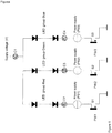
- Figure 2 shows a single power supply PS comprising N LED groups which are individually driven from a central processing unit (CPU).
- the number of LEDs that can be simultaneously ON is determined by the supply voltage divided by the maximum summed forward voltage of the LEDs.
- the CPU includes a clock which is sufficiently accurate to enable time control at adequate pulse width resolution (for example 10 bits at 1 kHz, i.e. 1 ms divided by 1024: ⁇ 1 ⁇ s.
- the CPU in this example controls the MOSFET switches by means of software, using a software-based pulse width generator, but a hardware-based generator is also an option.
- the power supply PS in this example has two fixed current settings; one for when at least one group is active, and a low current setting (or even OFF) if not a single group is active.
- the power supply PS can be an energy-inefficient linear (resistor or current-set transistor) or an energy-efficient switched version.
- a switched power supply PS consists of a current-feedback power supply which in principle consists of a pulse width-driven switch which is usually based on an integrated circuit and comprises a coil, flyback diode and a storage capacitor. In the case of a switched power supply PS it is necessary for the power supply PS to have a considerably higher regulating frequency than the pulse width modulation, to avoid undesirable oscillation interaction between the two loops. In addition to this example comprising two fixed current settings, another option is to implement the CPU with a dynamic current drive arrangement.
- the drive arrangement of the switches determines whether individual LED groups are active.
- the switch is formed by a MOSFET, because of the low Rds-on (ON resistance) and actuation speed, but in principle, a transistor or even an (electronic) relay would be among the possible options. If a switch is ON, the current from the power supply will pass through the switch and not through the LEDs. If a switch is OFF all the current will pass through the LEDs, which will then light up. To avoid voltage and current peaks, the LED groups are driven in such a way, by means of a (hardware or software) algorithm that only one switch is actuated in each time interval. An example of an algorithm follows hereinafter.
- the drive protocol of the LEDS over time can be static or dynamic (lightshow).
- a dynamic drive protocol can comprise an autonomous software routine which drives a local lightshow.
- the drive instructions can also be driven by a communications interface.
- a single light fitting among a set of such fittings can be appointed to coordinate a lightshow towards the other fittings (master/slave) by means of a bidirectional communications interface.
- the protocols for the communications interface can take many forms, for example direct control information for each colour and each unit of time, or parameterized instructions.
- the communications interface can consist of a galvanic, optical or RF link for data transmission purposes.
- one LED group shown includes a single LED, one group includes two LEDs connected in parallel, and one LED group shown includes M LEDs.
- the current will be split for each LED in this group, into two equal parts in the case of LEDs specially selected for this purpose (a customary principle in LED illumination). Allowing for component, current and voltage restrictions, the drive principle can be used in any combination of LED groups and LEDs in each group connected in parallel and in series.
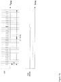
- FIG. 3 shows a flowchart of the pulse width-based drive algorithm which requires just a single actuation step per separation interval Tsepmin.
- Tsepmin is defined as the minimum time interval sufficient to accommodate the rise and fall times of the power supply in the case of a randomly selected LED group being energized or de-energized. This means that Tsepmin essentially corresponds to the rise or fall time of the power supply when the largest LED group connected to the power supply is energized or de-energized, respectively. This ensures that the current and the power supply have stabilized after a first LED group has been activated, prior to actuation of a second LED group.
- Figure 3 relates to an algorithmic example for N groups, many other algorithms being possible to achieve the same objective (at most one actuation event per interval Tsepmin ). Moreover, various implementations of this algorithm are possible, for example by sorting from high to low instead of the other way round as in the example.
- the algorithm example is defined so as to demand 100% of the CPU load. By redefining the implementation on an interrupt basis it is possible to re-use the stated wait times for other processor tasks such as external communication. Furthermore, it has now also been formulated in such a way that within each pulse width cycle all the results for a particular setting must be recalculated, but this can be avoided by storing the results for reuse in the following cycles.
- the algorithm for driving N LED groups consists of the following steps for each pulse width cycle, the starting point being that all LED groups are OFF (see Figures 4a and 4b for a concrete drive protocol example):
- an LED group includes an LED with the following drive percentages: Blue 100%, Green 30%, Red 25% and White 10%. Only White is "short", as the associated period is less than four times Tsepmin at a 1 ms interval making use of the algorithm as shown in Figure 3 .
- the horizontal axis here shows the time, the vertical axis showing the number of pulse width (PW) signals plotted against time.
- PW pulse width
- Figure 4b again shows the resulting power supply output voltage and current profile (assuming ideal LEDs with a voltage of 4 volts) in the case of the drive protocol as obtaining in Figure 4a .
- the horizontal axis again represents time, the top section of the figure showing the power supply output voltage as the vertical axis.
- the vertical axis is the current passing through the power supply, plotted against time. Shown in two locations in the figure is the Tsepmin time interval. Over time, the top picture shows that the highest power supply voltage is modulated at the instant when all LEDs are ON. The power supply is switched down to low at those times when CurrentLow is active and all the LEDs are OFF.
- Figure 5 shows an example of how at most three groups are simultaneously active and yet, on average, four LED groups are driven to a maximum capacity.
- the average current is 350 mA (at most, based on existing exemplary LED components), while the power supply is set to 500 mA (maximum peak current of existing exemplary LED components).
- time is shown on the horizontal axis, while four pulse width drive protocols (one for each colour) are plotted over time on the vertical axis. It can be clearly seen that all four pulse widths are ON for equally long times over the cycle (the Green pulse width is subdivided into two equal halves), while at any single moment there are never more than three groups that are simultaneously ON. With two LEDs per group it is then possible, using a 24 V supply voltage, to modulate up to 8 LEDs up to maximum capacity, instead of the usual 6.
- a further improvement of the drive principle of at least one Tsepmin between actuation events is achieved if at virtually the same instant (time difference less than the control bandwidth of the current source, i.e. the power supply, for example 0.5 ⁇ s for a 500 kHz current source) one LED group is deenergized and one LED group is energized (these being the only two events that are allowed to be combined).
- Figure 6 shows an example of this principle: the time is plotted horizontally, with two LED groups in the vertical.
- the pulse width cycle shows how, virtually at the same instant (+/- 0.5 ⁇ s) the White LED is turned OFF and the Blue LED is turned ON.
- any LED drive protocol By varying the pulse width, numbers and frequencies it is possible for any LED drive protocol to be implemented.
- This example also includes the option of supplying 8 LEDs from 24 V, since only at most 3 groups are simultaneously ON in combination with a peak current having a factor of 1.25 on top of the average current and a maximum modulation of 75%.
- Figure 9 sketches out a possibility of achieving a modulation percentage up to virtually 100% without the overcurrent principle, up to 4 groups therefore being ON simultaneously.
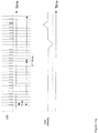
- Figure 10 shows that any LED intensity can be achieved by means of a combination of larger and smaller pulses P i , each operated with its own frequency F i .
- Figure 11a shows a small intensity transition, where three short pulses are replaced by one long one, uniformity not being ensured in the process. This figure shows the time horizontally and, from top to bottom, first of all the two intensities and then the intensity averaged over 16 ms per ms.
- the pulses are distributed in such a way over the 16 ms time interval, that the eye no longer detects the transition.
- the time is plotted horizontally, together with, from top to bottom, again the two intensities with a better pulse distribution, followed by the average intensity over 16 ms per ms.
- the groups of LEDs can be driven by one or more communications interfaces, many options existing for the communications interface of an LED fitting. Wide use is made of the so-called DMX protocol, other options being: power line communication (data transmission superimposed on the supply voltage, usually making use of a frequency or amplitude modulation method), or by means of a radio-frequency interface.
- a further addition to the drive principle is the option of defining the intensity of the LED logarithmically with respect to the modulation level received via the communications interface.
- the human eye is more sensitive to relative than to absolute intensities. This means that a difference of between 100 and 110 lumen is visible in a similar manner as between 1000 and 1100. This difference can be employed to achieve, by means of logarithmic conversion, a smooth transition from minimum modulation to maximum modulation, using fewer bits that need to be communicated via the communications network.
- This aspect can be employed, for example, in order to double the number of channels in a DMX network (for example from 16 bits to 8 bits per LED colour) while still achieving apparently similar quality.
- DMX is often used as a network standard.
- DXM is based on differential digital communication using a two-wire cable.
- Each DMX node (light fitting) taps off said two-wire bus.
- each LED fitting makes use, for example, of 9 switches to set a 9-bit address which is used to specify which byte of a 512 byte data stream the current channel information for an LED group starts from (the so-called start address).
- This configuration technique making use of switches means that during installation all the switches of each fitting can only be correctly set by hand, this process necessarily being repeated if a unit is replaced in the event of a fault.
- each node constitutes an impedance load for the DMX master output, and this is usually maximized to 32 nodes before a so-called DMX buffer has to be employed. For many applications, the limit of 32 is reached quite rapidly. Moreover, for distances greater than, in this example 30 m, it is necessary for the bus to be terminated, for signal reflection reasons, with a characteristic impedance, 30 m being a distance for the total network which likewise is rapidly reached in many applications. In practice, the termination is often forgotten or is not properly installed, quickly giving rise to problems. Another aspect that could give rise to reflection, are so-called T branches, which are therefore not permitted from this perspective.
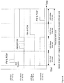
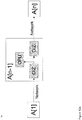
- Figure 12a shows a starting point fitting (A[1]), followed by a continuous loop up to and including fitting A[n].
- A[n-1] shows that each fitting includes a CPU to drive the LEDs (PWM or the algorithm-based modulation principles already mentioned hereinabove) and a network interface having two network connections or two transceivers for communication towards A[n-2] and A[n], respectively.
- the CPU is provided with all the channel information of the fitting upstream thereof.
- the CPU of a fitting will then trim ("consume") this information from the start by the number of channels required to drive the local LED groups and will then pass the remainder on to the next fitting. See Figure 12b1 for incoming data and 12b2 for outgoing data of an example involving the "consumption" of 3 channels.
- channels being “consumed” for each fitting the channel information is automatically distributed as required to channels of each individual fitting.
- a White LED fitting only takes off 1 channel, for example, and an RGB fitting takes off 3 channels. This consumption principle has the advantage that configuration is no longer necessary for a start address, resulting in lower component costs but also in less effort during installation.
- each fitting reads the channel information and stores it in a memory before passing it on, DMX buffers are not required, since each link has only two nodes.
- the terminating resistors have become virtually superfluous, since in a normal situation the distances between the fittings rarely exceed 30 m, a distance which is permitted between any two connected fittings.
- a type of T branch is also possible, a fitting acting as a local master. The signal integrity is fully restored in each fitting, allowing more cost-effective cable specifications.
- the incoming data stream rate is generated by a bit clock separate from that of the outgoing stream, a variation of two times 2% could in principle exist as the difference between incoming and outgoing bit rate for DMX (based on the RS485 standard).
- the continuous-loop principle can furthermore be readily combined with the normal bus-based wiring, giving rise to a kind of "local masters", see Figure 12c .
- the options for transmitting additional data from a fitting to the next one in the circuit allow matters such as 50/60 Hz synchronization (to avoid flicker effects owing to small differences in frequency between, for example, video cameras and the LED actuation instants) to be controlled centrally by the master which appends the zero passage information as phase status information to the data stream towards the next fitting.
- the LED modulation will then be synchronized by slightly retarding or accelerating the clock until a "lock" is achieved between the 50/60 Hz frequency and the modulation phase.
- FIG. 12c shows that fitting FM1 and FM2 are masters which, for "their" continuous-loop network generate the settings for the LEDS daisy-chained to each FM. Also shown are the temperature sensors T1 and T2 which can use a master to achieve the maximum setting of light (often thermally limited) at a particular ambient temperature: this has the further consequence that for the fittings coupled to the master there is less need for individual derating from the thermal limit of each. This has the advantage that there is less risk of differences in brightness, and the thermal sensor can possibly be linked on its own to the first fitting.
- Another possible advantage that local masters may offer is this: if, for example, the fittings linked thereto are all requires to have an identical output signal, the number of DMX channels required can be reduced, the local masters then ensuring the distribution of colour data to the daisy-chained fittings.
- the above described aspect of the invention can be articulated as a lighting unit comprising one or more LEDs, a supply unit for feeding the LEDs and a network interface, characterized in that the network interface is provided with a first network connection for communicating with an upstream lighting unit in the network and a second network connection for communicating with a downstream lighting unit in the network.
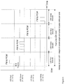
- an index value of the input DMX bus can be transmitted as "index + number of channels to be used locally" to the output bus. This allows each DMX node to determine which DMX channels are relevant for the self same node (the index value points at the current channel address), see Figure 12d1 and 12d2 , the incoming index of 5 ( Figure 12d1 ) indicating that the (e.g.) 3-channel fitting in question uses channels 5, 6 and 7. For the output data stream, the fitting adds 3 (number of channels used by the fitting) to the incoming data stream 5: 8 is transmitted to the next strip (see Figure 12d2 ).
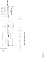
- the daisy-chain can also be combined with a simple operational interface (even down to a single switch or analogue input) and a DMX controller which is integrated in the CPU and is operated via said operational interface, resulting in a cost-effective and robust solution for simple, e.g. white-light, applications in which a switch starts and stops a dimming lightshow, see Figure 13a .
- the switch for example, serves as a selector between one scene or another, depending on the position of the switch, or the switch can serve as a pushbutton to start or stop a scene.
- Distribution of an analogue intensity signal is customary, but often entails stability and variation problems as a result of shielding and earthing issues.
- an analogue signal in this figure is passed on digitally as DMX channel values.
- DMX channel values digitally as DMX channel values.
- Another example is an RGB fitting having a built-in DMX controller in conjunction with a lightshow which varies through the RGB colour space and a simple user interface which allows a colour to be chosen by starting and stopping the DMX controller by means of the switch.
- Yet another application is to allow a sensor or switch to select or influence a lightshow, possibly using sensor information received from other network nodes.
- FIG. 14a shows an example of time compensation in the case of the "consumption" principle of the channel data in a fitting.
- FIG. 14b shows an example of time compensation in the case where the indexing principle of 2 is employed, one and the same or an additional index (in the figure provided with a circle) provides a measure of how long the wait is required for each fitting in order for the LEDs again to be able to be actuated at the same instant W.
- ABSM algorithm-based modulation
- a system could consist of a plurality of 15a circuits in a design where, for example, the TDM aspect of algorithm-based modulation ensures that peak currents are lower as a result of not all the power supplies always being actuated simultaneously and also possibly, not all being ON simultaneously.
- Figure 15b gives an example with a power supply connected to earth, a single system optionally also consisting of a number of 15b circuits. Again, 15b provides the advantages of TDM.
- Figures 15c and 15d show circuits with the possible option of using both the power supply controls and/or the switches via the LEDs.
- Figures 15e and 15f depict configurations in which a single power supply in the form of a connection in parallel can feed a number of circuits by means of the switches ABM1 to ABMm inclusive.
- a specific embodiment of this aspect of the invention can be formulated as a method of operating, using one or more power supplies, a number of high-power light-emitting diodes (LEDs), said number of LEDs being distributed over two or more groups, each group being separately energizable, characterized by a previously energized group being deenergized simultaneously with a subsequent one of the groups being energized.
- LEDs high-power light-emitting diodes
- LEDs high-power light-emitting diodes
- Time synchronization can be achieved by transmitting a time telegram from a point (CPU1). This is because correct reception at each fitting results in virtually simultaneous reception within a bit time of the bus communication, the synchronization accuracy at 2400 bits/sec in that case therefore being well below 1 ms, invisible to the human eye.
- the CPU2 and CPU3 in this example then each perform the same lightshow (each their own part), in which it does not matter if the communication fails from time to time, as long as the failure does not persist sufficiently long for the fittings' clocks to start to diverge significantly from one another.
- the CPU2 and CPU3 in this example then each perform the same lightshow (each their own part), in which it does not matter if the communication fails from time to time, as long as the failure does not persist sufficiently long for the fittings' clocks to start to diverge significantly from one another.
- highly dynamic and complex lightshows without suffering the consequences of a specific error percentage in the data communication.
- the idea described here can be formulated as a lighting system comprising a plurality of lighting units which are each provided with one or more LEDs and a central processing unit for driving the LEDs, wherein the central processing units are each provided with a memory for storing instructions for energizing and de-energizing the LEDs of the lighting unit in question, and wherein the lighting system comprises a communications network for transmitting, during operation, synchronization messages to one or more of the processing units, for the purpose of temporal matching of an energization and de-energization scenario of the LEDs of the lighting units.
- Another option is to transmit the programme to be performed (show) from the central master to all the nodes, therefore allowing a new lightshow to be selected.
- a further option is to provide "bridges", for example to wireless control elements or DMX networks, as LED setting information for the fittings or for reading sensor elements (temperature, smoke sensor and the like), see Figure 17 for a DMX interface linked to CPU1, where CPU1 then serves as a "bridge” between the DMX channels and the settings for CPU1 and CPU2 in this example.
- the aspect described here can be formulated as a lighting system comprising one or more lighting units, wherein driving of the lighting units, for example via a network, takes place by means of instructions for presenting an operational status of a switch and/or an operational status of a display segment or display point.
- a realistic assumption for the size of this script is that a command requires 1 byte, the abovementioned script then being about 20 bytes compared with the 4500 for DMX standard. Should the scene have to be repeated (a REPEAT script command), the gain would be multiplied.
- a lightshow designer is able to define a show which then, by means of a compiler and an optimizer (compact encoding) provides as compact as possible a parametric and scripted description which can be sent to the fittings, for execution, by means of a computer link.
- the aspect described here can be formulated as a lighting system comprising one or more lighting units, wherein driving of the lighting units, for example via a network, takes place by means of instructions in a parametric script.
Landscapes
- Led Devices (AREA)
- Circuit Arrangement For Electric Light Sources In General (AREA)
Claims (17)
- Beleuchtungssystem, welches eine oder mehrere Beleuchtungseinheiten umfasst,
wobei ein Ansteuern der Beleuchtungseinheiten mittels Anweisungen in einem Parameterskript stattfindet,
wobei das Beleuchtungssystem ausgestaltet ist, um eine skriptbasierte und parametrisierte Folgebeschreibung einer Lichtshow in die Beleuchtungseinheiten zu laden,
wobei die Beleuchtungseinheiten jeweils eine lokale Showsteuerung umfassen, welche in der Lage ist, die skriptbasierte und parametrisierte Folgebeschreibung zu interpretieren, um die Lichtshow auszuführen,
dadurch gekennzeichnet,
dass das Skript einen Bewegungsbefehl umfasst, welcher von Werten für Rot, Grün und Blau und einem Zeitwert gefolgt wird, und
wobei die lokale Showsteuerung ausgestaltet ist, um lineare Interpolationen von Rot, Grün und Blau von dem Bewegungsbefehl, den Werten von Rot, Grün und Blau und dem Zeitwert zu erzeugen. - Beleuchtungssystem nach Anspruch 1, wobei das Ansteuern der Beleuchtungseinheiten mittels eines Netzwerks ausgeführt wird.
- Beleuchtungssystem nach Anspruch 1, wobei eine Kommunikation mittels eines elektrischen Stromnetzes ausgeführt wird.
- Beleuchtungssystem nach einem der vorhergehenden Ansprüche, wobei die Beleuchtungseinheiten eine autonome Softwareroutine zum Ansteuern einer lokalen Lichtshow umfassen.
- Beleuchtungssystem nach einem der vorhergehenden Ansprüche, wobei das Skript einen Einstellungsbefehl, welcher von Werten für Rot, Grün und Blau gefolgt wird, umfasst.
- Beleuchtungssystem nach einem der vorhergehenden Ansprüche, wobei ein Befehl ein Byte erfordert.
- Beleuchtungssystem nach einem der vorhergehenden Ansprüche, wobei das Skript einen Wiederholungsbefehl umfasst.
- Beleuchtungssystem nach einem der vorhergehenden Ansprüche, wobei eine Zeitsynchronisation der Lichtshow mittels des Netzwerkes erzielt wird, indem ein Zeittelegramm übertragen wird.
- Verfahren zum Ansteuern von Beleuchtungseinheiten, wobei das Ansteuern der Beleuchtungseinheiten mittels Anweisungen in einem Parameterskript stattfindet, wobei eine skriptbasierte und parametrisierte Folgebeschreibung einer Lichtshow in die Beleuchtungseinheiten geladen wird und wobei die Lichtshow durch die Beleuchtungseinheiten ausgeführt wird, welche durch eine entsprechende Showsteuerung, die in jeder Beleuchtungseinheit enthalten ist, die skriptbasierte und parametrisierte Folgebeschreibung interpretieren,
dadurch gekennzeichnet,
dass das Skript einen Bewegungsbefehl umfasst, welcher von Werten für Rot, Grün und Blau und einem Zeitwert gefolgt wird, und
wobei lineare Interpolationen von Rot, Grün und Blau von dem Bewegungsbefehl, den Werten von Rot, Grün und Blau und dem Zeitwert erzeugt werden. - Verfahren nach Anspruch 9, wobei das Ansteuern der Beleuchtungseinheiten mittels eines Netzwerks ausgeführt wird.
- Verfahren nach Anspruch 9, wobei eine Kommunikation über ein elektrisches Stromnetz ausgeführt wird.
- Verfahren nach einem der Ansprüche 9 - 11, wobei eine lokale Lichtshow von einer Beleuchtungseinheit durch eine autonome Softwareroutine gesteuert wird.
- Verfahren nach einem der Ansprüche 9 - 12, wobei das Skript einen Einsteilungsbefehl umfasst, welcher von Werten für Rot, Grün und Blau gefolgt wird.
- Verfahren nach einem der Ansprüche 9 - 13, wobei ein Befehl ein Byte erfordert.
- Verfahren nach einem der Ansprüche 9 - 14, wobei das Skript einen Wiederholungsbefehl umfasst.
- Verfahren nach einem der Ansprüche 9 - 15, wobei eine Zeitsynchronisation der Lichtshow mittels des Netzwerks erzielt wird, indem ein Zeittelegramm übertragen wird.
- Verfahren nach einem der Ansprüche 9 - 16, welches darüber hinaus umfasst:- Definieren der Lichtshow;- Bereitstellen der skriptbasierten und parametrisierten Folgebeschreibung der definierten Lichtshow mittels eines Compilers und eines Optimierers, wobei die skriptbasierte und parametrisierte Folgebeschreibung in die Beleuchtungseinheiten über eine Computerverbindung geladen wird.
Applications Claiming Priority (5)
| Application Number | Priority Date | Filing Date | Title |
|---|---|---|---|
| NL1028728A NL1028728C1 (nl) | 2005-04-08 | 2005-04-08 | Werkwijze en inrichting voor het bedrijven van groepen hoog-vermogen LED's. |
| NL1029884A NL1029884C2 (nl) | 2005-04-08 | 2005-09-05 | Werkwijze en inrichting voor het bedrijven van groepen hoog-vermogen LED's. |
| NL1029943 | 2005-09-13 | ||
| PCT/NL2006/000182 WO2006107199A2 (en) | 2005-04-08 | 2006-04-07 | Methods and apparatuses for operating groups of high-power leds |
| EP06732989.6A EP1880583B1 (de) | 2005-04-08 | 2006-04-07 | Verfahren und vorrichtungen zum betrieb von gruppen von hochleistungs-leds |
Related Parent Applications (3)
| Application Number | Title | Priority Date | Filing Date |
|---|---|---|---|
| EP06732989.6 Division | 2006-04-07 | ||
| EP06732989.6A Division EP1880583B1 (de) | 2005-04-08 | 2006-04-07 | Verfahren und vorrichtungen zum betrieb von gruppen von hochleistungs-leds |
| EP06732989.6A Division-Into EP1880583B1 (de) | 2005-04-08 | 2006-04-07 | Verfahren und vorrichtungen zum betrieb von gruppen von hochleistungs-leds |
Publications (3)
| Publication Number | Publication Date |
|---|---|
| EP2309821A2 EP2309821A2 (de) | 2011-04-13 |
| EP2309821A3 EP2309821A3 (de) | 2011-12-21 |
| EP2309821B1 true EP2309821B1 (de) | 2020-11-18 |
Family
ID=36758641
Family Applications (2)
| Application Number | Title | Priority Date | Filing Date |
|---|---|---|---|
| EP06732989.6A Active EP1880583B1 (de) | 2005-04-08 | 2006-04-07 | Verfahren und vorrichtungen zum betrieb von gruppen von hochleistungs-leds |
| EP10191577.5A Active EP2309821B1 (de) | 2005-04-08 | 2006-04-07 | Verfahren und Vorrichtungen zum Betrieb von Gruppen von Hochleistungs-LEDs |
Family Applications Before (1)
| Application Number | Title | Priority Date | Filing Date |
|---|---|---|---|
| EP06732989.6A Active EP1880583B1 (de) | 2005-04-08 | 2006-04-07 | Verfahren und vorrichtungen zum betrieb von gruppen von hochleistungs-leds |
Country Status (5)
| Country | Link |
|---|---|
| US (4) | US8207691B2 (de) |
| EP (2) | EP1880583B1 (de) |
| JP (4) | JP2008535279A (de) |
| CA (4) | CA2601731C (de) |
| WO (1) | WO2006107199A2 (de) |
Families Citing this family (159)
| Publication number | Priority date | Publication date | Assignee | Title |
|---|---|---|---|---|
| CA2564659C (en) | 2005-11-10 | 2013-08-20 | Jason Neudorf | Modulation method and apparatus for dimming and/or colour mixing leds |
| US8791645B2 (en) | 2006-02-10 | 2014-07-29 | Honeywell International Inc. | Systems and methods for controlling light sources |
| DE102006032071B4 (de) * | 2006-07-11 | 2008-07-10 | Austriamicrosystems Ag | Steuerschaltung und Verfahren zum Steuern von Leuchtdioden |
| JP2010507889A (ja) * | 2006-10-27 | 2010-03-11 | コーニンクレッカ フィリップス エレクトロニクス エヌ ヴィ | 複数の光源の中から選択された光源の光束を測定するための方法及び装置 |
| JP5366815B2 (ja) * | 2006-11-10 | 2013-12-11 | フィリップス ソリッド−ステート ライティング ソリューションズ インコーポレイテッド | 直列接続されたledを制御する方法及び装置 |
| CN200979092Y (zh) * | 2006-12-07 | 2007-11-21 | 姚荣湘 | 串联型led灯组发光装置 |
| JP5089193B2 (ja) * | 2007-02-22 | 2012-12-05 | 株式会社小糸製作所 | 発光装置 |
| US8035320B2 (en) | 2007-04-20 | 2011-10-11 | Sibert W Olin | Illumination control network |
| WO2008129504A1 (en) * | 2007-04-24 | 2008-10-30 | Philips Intellectual Property & Standards Gmbh | Led string driver with shift register and level shifter |
| JP5026146B2 (ja) * | 2007-05-24 | 2012-09-12 | シャープ株式会社 | 発光ダイオード駆動装置 |
| JP5337153B2 (ja) * | 2007-07-02 | 2013-11-06 | コーニンクレッカ フィリップス エヌ ヴェ | 負荷のための駆動装置及びこのような駆動装置を用いて負荷を駆動させる方法 |
| US8259058B2 (en) * | 2007-07-12 | 2012-09-04 | Semtech International Ag | Method and device for controlling the backlighting of a flat screen |
| DE102007034177B4 (de) * | 2007-07-23 | 2009-06-10 | Diehl Aerospace Gmbh | Verfahren zum Dimmen des von LED-Leuchten abgestrahlten Lichts, insbesondere in der Fluggastkabine eines Verkehrsflugzeuges |
| US8188679B2 (en) | 2007-07-23 | 2012-05-29 | Nxp B.V. | Self-powered LED bypass-switch configuration |
| FR2919457A1 (fr) * | 2007-07-27 | 2009-01-30 | Marc Didier Patrick Pettmann | Dispositif d'alimentation de diodes electroluminescentes principalement rvb (led) dote d'une double programmation de courants reglables en continu,d'un afficheur et d'une aide aux reglages. |
| JP5172500B2 (ja) * | 2007-07-27 | 2013-03-27 | ローム株式会社 | 駆動装置 |
| JP5007650B2 (ja) * | 2007-10-16 | 2012-08-22 | ソニー株式会社 | 表示装置、表示装置の光量調整方法ならびに電子機器 |
| JP2009134933A (ja) * | 2007-11-29 | 2009-06-18 | Mitsubishi Electric Corp | Led点灯装置および車両用前照灯 |
| RU2481752C2 (ru) * | 2007-12-07 | 2013-05-10 | Конинклейке Филипс Электроникс Н.В. | Система и способ управления электропитанием сид лампы |
| ES2340455B1 (es) * | 2008-01-10 | 2011-05-16 | Senia Technologies, S.L. | Circuito de control para encendido y apagado de led's constitutivos de una pantalla publicitaria. |
| US20090179574A1 (en) * | 2008-01-16 | 2009-07-16 | Hsiu-Hui Chang | Backlight module of light emitting diode |
| WO2009093895A1 (en) * | 2008-01-21 | 2009-07-30 | Eldolab Holding B.V. | A method for producing a led assembly and led assembly produced by the method |
| WO2009092443A1 (de) * | 2008-01-24 | 2009-07-30 | Osram Gesellschaft mit beschränkter Haftung | Verfahren und schaltungsanordnung zur zweistufigen regelung von halbleiterlichtquellen. |
| JP5141277B2 (ja) | 2008-02-08 | 2013-02-13 | ソニー株式会社 | 点灯期間設定方法、表示パネルの駆動方法、バックライトの駆動方法、点灯期間設定装置、半導体デバイス、表示パネル及び電子機器 |
| US8007286B1 (en) | 2008-03-18 | 2011-08-30 | Metrospec Technology, Llc | Circuit boards interconnected by overlapping plated through holes portions |
| US11266014B2 (en) | 2008-02-14 | 2022-03-01 | Metrospec Technology, L.L.C. | LED lighting systems and method |
| JP5211732B2 (ja) | 2008-02-14 | 2013-06-12 | ソニー株式会社 | 点灯期間設定方法、表示パネルの駆動方法、点灯条件設定装置、半導体デバイス、表示パネル及び電子機器 |
| US10334735B2 (en) | 2008-02-14 | 2019-06-25 | Metrospec Technology, L.L.C. | LED lighting systems and methods |
| US8143631B2 (en) | 2008-03-06 | 2012-03-27 | Metrospec Technology Llc | Layered structure for use with high power light emitting diode systems |
| US8851356B1 (en) | 2008-02-14 | 2014-10-07 | Metrospec Technology, L.L.C. | Flexible circuit board interconnection and methods |
| WO2009102192A1 (en) * | 2008-02-15 | 2009-08-20 | Eldolab Holding B.V. | Illumination system comprising a light source and a control unit and an illumination control system for controlling a light source by multiple user interface surfaces |
| WO2009116854A2 (en) * | 2008-03-17 | 2009-09-24 | Eldolab Holding B.V. | Led assembly, led fixture, control method and software program |
| US8410720B2 (en) * | 2008-04-07 | 2013-04-02 | Metrospec Technology, LLC. | Solid state lighting circuit and controls |
| US8994615B2 (en) | 2008-06-06 | 2015-03-31 | Dolby Laboratories Licensing Corporation | Apparatus and methods for driving solid-state illumination sources |
| TWI459858B (zh) * | 2008-06-24 | 2014-11-01 | Eldolab Holding Bv | 照明系統及發光二極體組件之控制單元 |
| WO2010005291A1 (en) | 2008-07-11 | 2010-01-14 | Eldolab Holding B.V. | Power converter for an led assembly and lighting application |
| WO2010015278A1 (de) * | 2008-08-04 | 2010-02-11 | Osram Gesellschaft mit beschränkter Haftung | Betriebsverfahren und schaltungsanordnung zum getakteten betrieb mehrerer farbiger halbleiterlichtquellen für die projektion bildhafter inhalte und bewegter bilder |
| TWI580305B (zh) * | 2008-09-05 | 2017-04-21 | 艾杜雷控股有限公司 | 以發光二極體為光源之照明系統 |
| US7986102B2 (en) * | 2008-09-12 | 2011-07-26 | General Electric Company | Adjustable color solid state lighting |
| US8957601B2 (en) | 2008-09-18 | 2015-02-17 | Lumastream Canada Ulc | Configurable LED driver/dimmer for solid state lighting applications |
| JP2010109168A (ja) | 2008-10-30 | 2010-05-13 | Fuji Electric Systems Co Ltd | Led駆動装置、led駆動方法および照明装置 |
| US7986107B2 (en) * | 2008-11-06 | 2011-07-26 | Lumenetix, Inc. | Electrical circuit for driving LEDs in dissimilar color string lengths |
| EP2366269B1 (de) * | 2008-11-13 | 2012-10-10 | Koninklijke Philips Electronics N.V. | Beleuchtungssystem mit mehreren leds |
| US9125261B2 (en) | 2008-11-17 | 2015-09-01 | Express Imaging Systems, Llc | Electronic control to regulate power for solid-state lighting and methods thereof |
| US8232742B2 (en) | 2008-11-27 | 2012-07-31 | Arkalumen Inc. | Method, apparatus and computer-readable media for controlling lighting devices |
| EP2374333B1 (de) * | 2008-12-04 | 2014-01-08 | Koninklijke Philips N.V. | Beleuchtungsanordnung und verfahren zum einbetten eines datensignals in eine luminanzausgabe unter verwendung von mit wechselstrom betriebenen lichtquellen |
| US8497478B2 (en) * | 2009-03-31 | 2013-07-30 | Osram Sylvania Inc. | High voltage supply to increase rise time of current through light source in an optical sensor system |
| EP2422584B1 (de) | 2009-04-21 | 2013-11-20 | Koninklijke Philips N.V. | System zur ansteuerung einer lampe |
| EP3190862B1 (de) | 2009-05-04 | 2019-07-03 | eldoLAB Holding B.V. | Steuereinheit für eine led-anordnung und beleuchtungssystem |
| DE102009025752B4 (de) * | 2009-05-06 | 2011-06-16 | Lear Corp. | Verfahren und Schaltungsanordnung zur Ansteuerung einer Last |
| WO2010135575A2 (en) | 2009-05-20 | 2010-11-25 | Express Imaging Systems, Llc | Long-range motion detection for illumination control |
| US8410717B2 (en) * | 2009-06-04 | 2013-04-02 | Point Somee Limited Liability Company | Apparatus, method and system for providing AC line power to lighting devices |
| US8324840B2 (en) * | 2009-06-04 | 2012-12-04 | Point Somee Limited Liability Company | Apparatus, method and system for providing AC line power to lighting devices |
| US8569956B2 (en) | 2009-06-04 | 2013-10-29 | Point Somee Limited Liability Company | Apparatus, method and system for providing AC line power to lighting devices |
| EP2468071B1 (de) | 2009-08-18 | 2014-07-02 | EldoLAB Holding B.V. | Steuereinheit für eine led-anordnung und beleuchtungssystem |
| CN102006699B (zh) * | 2009-09-02 | 2013-04-17 | 海洋王照明科技股份有限公司 | 一种警用拍照灯电路 |
| DE102009040283A1 (de) * | 2009-09-04 | 2011-03-10 | Tridonic Ag | Betrieb von pulsmodulierten LEDs |
| US8629622B2 (en) * | 2009-09-04 | 2014-01-14 | Koninklijke Philips N.V. | Light emitting diode circuit |
| JP5785557B2 (ja) * | 2009-12-11 | 2015-09-30 | コーニンクレッカ フィリップス エヌ ヴェ | 照明回路用の駆動モード |
| CN201663727U (zh) * | 2009-12-18 | 2010-12-01 | 国琏电子(上海)有限公司 | 旁路保护电路及使用其的发光二极管驱动装置 |
| KR20110096319A (ko) * | 2010-02-22 | 2011-08-30 | 테라링크 커뮤니케이션스(주) | 적외선 송신 장치 |
| DE102010015904B4 (de) * | 2010-03-10 | 2016-12-15 | Lear Corporation Gmbh | Verfahren zur Ansteuerung einer elektrischen Last |
| DE102010015908B4 (de) * | 2010-03-10 | 2013-10-24 | Lear Corporation Gmbh | Vorrichtung zur Ansteuerung einer elektrischen Last |
| DE102010002758A1 (de) * | 2010-03-11 | 2011-09-15 | Tridonic Gmbh & Co Kg | Bus-Gebäudetechniksystem mit Daisy-Chain Topologie |
| DE102010003244A1 (de) * | 2010-03-25 | 2011-09-29 | Osram Gesellschaft mit beschränkter Haftung | Verfahren und Schaltungsanordnung zum Betreiben einer Vielzahl von Leds |
| DE102010013493A1 (de) * | 2010-03-31 | 2011-10-06 | Osram Opto Semiconductors Gmbh | Optoelektronische Vorrichung |
| EP2373125B1 (de) | 2010-04-01 | 2012-08-22 | GLP German Light Products GmbH | Vorrichtung zur Erzeugung eines Antriebssignals für eine Lampenvorrichtung und Verfahren zur Erzeugung eines Antriebssignals für eine Lampenvorrichtung |
| JP2013519988A (ja) * | 2010-04-01 | 2013-05-30 | ジーエルピー・ジャーマン・ライト・プロダクツ・ゲーエムベーハー | 照明装置の駆動信号を生成する装置及び方法 |
| DE102010003739B4 (de) * | 2010-04-08 | 2012-12-06 | Osram Ag | Schaltungsanordnung zum Betreiben einer Vielzahl von Leds |
| DE102010019205A1 (de) * | 2010-05-04 | 2011-12-01 | Hella Kgaa Hueck & Co. | Schaltungsanordnung mit einem LED-Strang und Verfahren zum Ansteuern des LED-Strangs |
| US9086435B2 (en) | 2011-05-10 | 2015-07-21 | Arkalumen Inc. | Circuits for sensing current levels within a lighting apparatus incorporating a voltage converter |
| US8564214B2 (en) | 2010-05-11 | 2013-10-22 | Arkalumen Inc. | Circuits for sensing current levels within lighting apparatus |
| US9089024B2 (en) | 2010-05-11 | 2015-07-21 | Arkalumen Inc. | Methods and apparatus for changing a DC supply voltage applied to a lighting circuit |
| WO2012033410A2 (en) | 2010-09-10 | 2012-03-15 | Eldolab Holding B.V. | Led driver circuit and method |
| US20120075596A1 (en) * | 2010-09-24 | 2012-03-29 | Hannah Eric C | High efficiency illumination |
| US8159153B2 (en) * | 2010-10-01 | 2012-04-17 | Bridgelux, Inc. | LED light sources with improved thermal compensation |
| DE102010060857B4 (de) * | 2010-11-29 | 2024-01-11 | HELLA GmbH & Co. KGaA | Schaltungsanordnung mit einem Leuchtdiodenfeld, Steuer- und/oder Regelungsmittel für das Leuchtdiodenfeld sowie Verfahren zum Betreiben einer solchen Schaltungsanordnung |
| US9192009B2 (en) | 2011-02-14 | 2015-11-17 | Arkalumen Inc. | Lighting apparatus and method for detecting reflected light from local objects |
| WO2012122638A1 (en) | 2011-03-16 | 2012-09-20 | Arkalumen Inc. | Lighting apparatus and methods for controlling lighting apparatus using ambient light levels |
| US8939604B2 (en) | 2011-03-25 | 2015-01-27 | Arkalumen Inc. | Modular LED strip lighting apparatus |
| US8901825B2 (en) | 2011-04-12 | 2014-12-02 | Express Imaging Systems, Llc | Apparatus and method of energy efficient illumination using received signals |
| US9060400B2 (en) | 2011-07-12 | 2015-06-16 | Arkalumen Inc. | Control apparatus incorporating a voltage converter for controlling lighting apparatus |
| BR112014005999A2 (pt) * | 2011-09-19 | 2017-04-04 | Koninklijke Philips Nv | sistema de driver para led, lâmpada e método de acionamento de um led em um sistema |
| JP6057906B2 (ja) * | 2011-10-04 | 2017-01-11 | シチズン時計株式会社 | Led照明装置 |
| US9730294B2 (en) | 2011-11-07 | 2017-08-08 | GE Lighting Solutions, LLC | Lighting device including a drive device configured for dimming light-emitting diodes |
| US9360198B2 (en) | 2011-12-06 | 2016-06-07 | Express Imaging Systems, Llc | Adjustable output solid-state lighting device |
| US8917026B2 (en) | 2011-12-20 | 2014-12-23 | Lumenetix, Inc. | Linear bypass electrical circuit for driving LED strings |
| US9491838B2 (en) * | 2012-01-26 | 2016-11-08 | Texas Instruments Incorporated | LED matrix manager |
| US9497393B2 (en) | 2012-03-02 | 2016-11-15 | Express Imaging Systems, Llc | Systems and methods that employ object recognition |
| US9210751B2 (en) | 2012-05-01 | 2015-12-08 | Express Imaging Systems, Llc | Solid state lighting, drive circuit and method of driving same |
| US9204523B2 (en) | 2012-05-02 | 2015-12-01 | Express Imaging Systems, Llc | Remotely adjustable solid-state lamp |
| US9398656B2 (en) * | 2012-05-16 | 2016-07-19 | Beijing EffiLED Opto-Electronics Technology Co., Ltd. | Device and method for driving an LED light |
| US8816591B2 (en) * | 2012-05-26 | 2014-08-26 | Vastview Technology Inc. | Methods and apparatus for segmenting and driving LED-based lighting units |
| JP5942256B2 (ja) | 2012-06-08 | 2016-06-29 | パナソニックIpマネジメント株式会社 | 点灯装置及び照明器具 |
| US9131552B2 (en) | 2012-07-25 | 2015-09-08 | Express Imaging Systems, Llc | Apparatus and method of operating a luminaire |
| US8896215B2 (en) | 2012-09-05 | 2014-11-25 | Express Imaging Systems, Llc | Apparatus and method for schedule based operation of a luminaire |
| US9185766B2 (en) * | 2012-10-11 | 2015-11-10 | General Electric Company | Rolling blackout adjustable color LED illumination source |
| US9301365B2 (en) | 2012-11-07 | 2016-03-29 | Express Imaging Systems, Llc | Luminaire with switch-mode converter power monitoring |
| US9210759B2 (en) | 2012-11-19 | 2015-12-08 | Express Imaging Systems, Llc | Luminaire with ambient sensing and autonomous control capabilities |
| US9485827B2 (en) | 2012-11-22 | 2016-11-01 | Sct Technology, Ltd. | Apparatus and method for driving LED display panel |
| DE102013100663A1 (de) * | 2013-01-23 | 2014-07-24 | Osram Opto Semiconductors Gmbh | Anordnung und Verfahren zum Betreiben einer Anordnung |
| US9258861B2 (en) * | 2013-02-02 | 2016-02-09 | Vastview Technology Inc. | Apparatus for driving multi-color LED strings |
| US9288873B2 (en) | 2013-02-13 | 2016-03-15 | Express Imaging Systems, Llc | Systems, methods, and apparatuses for using a high current switching device as a logic level sensor |
| JP5422068B2 (ja) * | 2013-02-15 | 2014-02-19 | 三菱電機株式会社 | Led点灯装置および車両用前照灯 |
| US9743473B2 (en) | 2013-03-15 | 2017-08-22 | Lumenetix, Inc. | Cascade LED driver and control methods |
| US9466443B2 (en) | 2013-07-24 | 2016-10-11 | Express Imaging Systems, Llc | Photocontrol for luminaire consumes very low power |
| US9924584B2 (en) * | 2013-10-29 | 2018-03-20 | James David Smith | Method and device capable of unique pattern control of pixel LEDs via smaller number of DMX control channels |
| US9414449B2 (en) | 2013-11-18 | 2016-08-09 | Express Imaging Systems, Llc | High efficiency power controller for luminaire |
| DE102013223711A1 (de) * | 2013-11-20 | 2015-05-21 | Osram Gmbh | Steuern eines wenigstens zwei Halbleiterlichtquellen aufweisenden Leuchtmittels |
| DE102013223710A1 (de) * | 2013-11-20 | 2015-05-21 | Osram Gmbh | Steuern eines wenigstens zwei Halbleiterlichtquellen aufweisenden Leuchtmittels |
| JP2015111507A (ja) * | 2013-12-06 | 2015-06-18 | キヤノン株式会社 | 照明装置及びその制御方法 |
| US9185777B2 (en) | 2014-01-30 | 2015-11-10 | Express Imaging Systems, Llc | Ambient light control in solid state lamps and luminaires |
| CN104135804A (zh) * | 2014-08-14 | 2014-11-05 | 合肥云杉光电科技有限公司 | 一种三相电整流lc高pf滤波直流高压直驱led电路 |
| KR101698346B1 (ko) * | 2014-08-28 | 2017-01-20 | (주)선일일렉콤 | 별도의 배선없이 led 조명 제어를 수행하는 교류전원 벽스위치 |
| KR101552673B1 (ko) * | 2014-09-24 | 2015-09-11 | 태석정공 주식회사 | 엘이디 모듈 및 이에 의한 엘이디 램프 |
| WO2016054085A1 (en) | 2014-09-30 | 2016-04-07 | Express Imaging Systems, Llc | Centralized control of area lighting hours of illumination |
| WO2016064542A1 (en) | 2014-10-24 | 2016-04-28 | Express Imaging Systems, Llc | Detection and correction of faulty photo controls in outdoor luminaires |
| US10980121B2 (en) | 2015-02-16 | 2021-04-13 | Nthdegree Technologies Worldwide Inc. | Printed LED driver circuit |
| US9462662B1 (en) | 2015-03-24 | 2016-10-04 | Express Imaging Systems, Llc | Low power photocontrol for luminaire |
| US10568180B2 (en) | 2015-05-05 | 2020-02-18 | Arkalumen Inc. | Method and apparatus for controlling a lighting module having a plurality of LED groups |
| US10225904B2 (en) | 2015-05-05 | 2019-03-05 | Arkalumen, Inc. | Method and apparatus for controlling a lighting module based on a constant current level from a power source |
| US9992836B2 (en) | 2015-05-05 | 2018-06-05 | Arkawmen Inc. | Method, system and apparatus for activating a lighting module using a buffer load module |
| US9992829B2 (en) | 2015-05-05 | 2018-06-05 | Arkalumen Inc. | Control apparatus and system for coupling a lighting module to a constant current DC driver |
| US9775211B2 (en) | 2015-05-05 | 2017-09-26 | Arkalumen Inc. | Circuit and apparatus for controlling a constant current DC driver output |
| CN106488621B (zh) * | 2015-08-25 | 2021-02-12 | 西门子瑞士有限公司 | 通知设备 |
| US9538612B1 (en) | 2015-09-03 | 2017-01-03 | Express Imaging Systems, Llc | Low power photocontrol for luminaire |
| CN105472264B (zh) * | 2015-11-25 | 2018-09-14 | 浙江意博高科技术有限公司 | 一种卷帘式快门曝光摄像机用led补光控制电路 |
| NL2016424B1 (en) | 2016-03-11 | 2017-10-02 | Eldolab Holding Bv | Modular lighting application. |
| NL2016662B1 (en) * | 2016-04-22 | 2017-11-16 | Eldolab Holding Bv | Modular lighting application. |
| US9924582B2 (en) | 2016-04-26 | 2018-03-20 | Express Imaging Systems, Llc | Luminaire dimming module uses 3 contact NEMA photocontrol socket |
| CN106068046A (zh) * | 2016-04-27 | 2016-11-02 | 佛山市锐霸电子有限公司 | 多路光源调节电路 |
| EP3244697B1 (de) * | 2016-05-13 | 2020-07-29 | Rohm Co., Ltd. | Verfahren und vorrichtung zur reduktion von flimmern von emittiertem licht |
| US9820343B1 (en) * | 2016-07-25 | 2017-11-14 | Infineon Technologies Ag | Light-emitting diode headlight driver |
| CN109691235B (zh) * | 2016-09-09 | 2021-02-19 | 株式会社小糸制作所 | 点亮电路、车辆用灯具及光源的驱动方法 |
| US10230296B2 (en) | 2016-09-21 | 2019-03-12 | Express Imaging Systems, Llc | Output ripple reduction for power converters |
| US9985429B2 (en) | 2016-09-21 | 2018-05-29 | Express Imaging Systems, Llc | Inrush current limiter circuit |
| FR3059858A1 (fr) * | 2016-12-05 | 2018-06-08 | Orange | Dispositif de communication adapte pour des habitacles, notamment de vehicules automobiles |
| US10098212B2 (en) | 2017-02-14 | 2018-10-09 | Express Imaging Systems, Llc | Systems and methods for controlling outdoor luminaire wireless network using smart appliance |
| US10568191B2 (en) | 2017-04-03 | 2020-02-18 | Express Imaging Systems, Llc | Systems and methods for outdoor luminaire wireless control |
| US10219360B2 (en) | 2017-04-03 | 2019-02-26 | Express Imaging Systems, Llc | Systems and methods for outdoor luminaire wireless control |
| US10904992B2 (en) | 2017-04-03 | 2021-01-26 | Express Imaging Systems, Llc | Systems and methods for outdoor luminaire wireless control |
| US11375599B2 (en) | 2017-04-03 | 2022-06-28 | Express Imaging Systems, Llc | Systems and methods for outdoor luminaire wireless control |
| JP6916668B2 (ja) * | 2017-05-26 | 2021-08-11 | 株式会社小糸製作所 | 車両用灯具および光源の点灯回路 |
| JP2019029529A (ja) * | 2017-07-31 | 2019-02-21 | パナソニック デバイスSunx株式会社 | 紫外線照射装置 |
| EP3673716A1 (de) * | 2017-08-23 | 2020-07-01 | Wiz Connected Lighting Co. Limited | System und verfahren zur steuerung der ausgabe einer dynamischen beleuchtungsszene durch eine gruppe von beleuchtungseinheiten |
| CN112566817A (zh) * | 2018-08-27 | 2021-03-26 | 株式会社小糸制作所 | 点亮电路及车辆用灯具 |
| US10849200B2 (en) | 2018-09-28 | 2020-11-24 | Metrospec Technology, L.L.C. | Solid state lighting circuit with current bias and method of controlling thereof |
| US10362653B1 (en) * | 2018-10-05 | 2019-07-23 | Ledvance Llc | Isolated dimming circuit |
| CA3116939C (en) | 2018-10-26 | 2023-08-15 | Mate. Llc | Inrush current limited ac/dc power converter apparatus and method |
| JP6959273B2 (ja) * | 2019-01-31 | 2021-11-02 | 矢崎総業株式会社 | 制御装置、照明装置、及び、制御装置のプログラム |
| DE102019105954A1 (de) | 2019-03-08 | 2020-09-10 | HELLA GmbH & Co. KGaA | Steuer- und/oder Regelungsmittel, Schaltungsanordnung und Verfahren zur Reduzierung des Strommaximums in einem Leuchtdiodenfeld |
| DE102019106527A1 (de) | 2019-03-14 | 2020-09-17 | OSRAM Opto Semiconductors Gesellschaft mit beschränkter Haftung | Verfahren zum betrieb einer optischen anzeigevorrichtung und optische anzeigevorrichtung |
| US11234304B2 (en) | 2019-05-24 | 2022-01-25 | Express Imaging Systems, Llc | Photocontroller to control operation of a luminaire having a dimming line |
| US11317497B2 (en) | 2019-06-20 | 2022-04-26 | Express Imaging Systems, Llc | Photocontroller and/or lamp with photocontrols to control operation of lamp |
| CN110139437A (zh) * | 2019-06-21 | 2019-08-16 | 江苏宜美照明科技股份有限公司 | 一种可变功率的led筒灯 |
| JP7230200B2 (ja) * | 2019-06-28 | 2023-02-28 | 京セラ株式会社 | 照明装置、照明制御方法及び照明制御プログラム |
| US11212887B2 (en) | 2019-11-04 | 2021-12-28 | Express Imaging Systems, Llc | Light having selectively adjustable sets of solid state light sources, circuit and method of operation thereof, to provide variable output characteristics |
| US11153947B2 (en) | 2019-12-11 | 2021-10-19 | Viza Electronics Pte. Ltd. | Dimming and mixing light emitting diodes using reduced pulse widths |
| KR20220048718A (ko) * | 2020-10-13 | 2022-04-20 | 현대자동차주식회사 | 단일 채널 기반 다기능 led 램프 구동 시스템 및 방법 |
Citations (2)
| Publication number | Priority date | Publication date | Assignee | Title |
|---|---|---|---|---|
| WO2004094896A2 (en) * | 2003-04-21 | 2004-11-04 | Color Kinetics, Inc. | Tile lighting methods and systems |
| WO2004100624A2 (en) * | 2003-05-05 | 2004-11-18 | Color Kinetics, Inc. | Lighting methods and systems |
Family Cites Families (34)
| Publication number | Priority date | Publication date | Assignee | Title |
|---|---|---|---|---|
| US4017847A (en) * | 1975-11-14 | 1977-04-12 | Bell Telephone Laboratories, Incorporated | Luminous indicator with zero standby power |
| US5010459A (en) * | 1986-07-17 | 1991-04-23 | Vari-Lite, Inc. | Console/lamp unit coordination and communication in lighting systems |
| JPH02205367A (ja) * | 1989-02-03 | 1990-08-15 | Sumitomo Electric Ind Ltd | 発光素子駆動回路 |
| JPH0981211A (ja) | 1995-09-14 | 1997-03-28 | Hitachi Ltd | 表示回路およびプログラマブルコントローラ |
| JPH1132278A (ja) * | 1997-07-10 | 1999-02-02 | Fuji Xerox Co Ltd | プロジェクタ装置 |
| US6869204B2 (en) * | 1997-08-26 | 2005-03-22 | Color Kinetics Incorporated | Light fixtures for illumination of liquids |
| US7353071B2 (en) * | 1999-07-14 | 2008-04-01 | Philips Solid-State Lighting Solutions, Inc. | Method and apparatus for authoring and playing back lighting sequences |
| JPH11119733A (ja) | 1997-10-16 | 1999-04-30 | Toyoda Gosei Co Ltd | 発光ダイオードの電源装置 |
| JP3994505B2 (ja) | 1998-02-09 | 2007-10-24 | ソニー株式会社 | 照明装置 |
| EP0967590A1 (de) | 1998-06-25 | 1999-12-29 | Hewlett-Packard Company | Optische Anzeigevorrichtung mit Leuchtdioden und Steuerverfahren dafür |
| US7161556B2 (en) * | 2000-08-07 | 2007-01-09 | Color Kinetics Incorporated | Systems and methods for programming illumination devices |
| JP3957150B2 (ja) * | 2001-02-08 | 2007-08-15 | セイコーインスツル株式会社 | Led駆動回路 |
| US7088334B2 (en) * | 2001-06-28 | 2006-08-08 | Matsushita Electric Industrial Co., Ltd. | Liquid crystal display device and manufacturing method thereof, and drive control method of lighting unit |
| TW571119B (en) * | 2001-12-20 | 2004-01-11 | Delta Electronics Inc | Image projection device with integrated semiconductor light emitting element light source |
| JP2003197970A (ja) * | 2001-12-28 | 2003-07-11 | Toshiba Lighting & Technology Corp | 発光ダイオード駆動回路および機器 |
| JP3685134B2 (ja) | 2002-01-23 | 2005-08-17 | セイコーエプソン株式会社 | 液晶ディスプレイのバックライト制御装置および液晶ディスプレイ |
| JP2003332623A (ja) | 2002-05-07 | 2003-11-21 | Rohm Co Ltd | 発光素子駆動装置及び、発光素子を備えた電子機器 |
| US6812653B2 (en) * | 2002-07-26 | 2004-11-02 | Richard S. Bellivean | Method and apparatus for controlling images with image projection lighting devices |
| JP4073272B2 (ja) * | 2002-08-29 | 2008-04-09 | シチズン電子株式会社 | カラー表示装置およびカラー表示装置の白色バランス調整方法 |
| US20040090403A1 (en) * | 2002-11-08 | 2004-05-13 | Dynascan Technology Corp. | Light-emitting diode display apparatus with low electromagnetic display |
| JP2004207411A (ja) | 2002-12-25 | 2004-07-22 | Nec Saitama Ltd | Led表示装置及びその点灯方法並びにプログラム |
| US6927545B2 (en) * | 2003-03-10 | 2005-08-09 | Richard S. Belliveau | Image projection lighting device displays and interactive images |
| KR20050091701A (ko) | 2003-04-01 | 2005-09-15 | 가부시키가이샤 휴네트 | Led 구동장치 및 led 구동방법 |
| JP4076083B2 (ja) * | 2003-04-01 | 2008-04-16 | 株式会社Hdt | Ledの駆動電圧設定装置及びその方法 |
| JP4959324B2 (ja) * | 2003-05-07 | 2012-06-20 | コーニンクレッカ フィリップス エレクトロニクス エヌ ヴィ | 複数の発光ダイオードのための単一ドライバ |
| GB0325731D0 (en) * | 2003-09-09 | 2003-12-10 | Sentec Ltd | Controller circuit |
| US7233115B2 (en) * | 2004-03-15 | 2007-06-19 | Color Kinetics Incorporated | LED-based lighting network power control methods and apparatus |
| US7129652B2 (en) * | 2004-03-26 | 2006-10-31 | Texas Instruments Incorporated | System and method for driving a plurality of loads |
| US7202608B2 (en) * | 2004-06-30 | 2007-04-10 | Tir Systems Ltd. | Switched constant current driving and control circuit |
| US20060038803A1 (en) * | 2004-08-20 | 2006-02-23 | Semiconductor Components Industries, Llc | LED control method and structure therefor |
| US8624895B2 (en) * | 2005-01-20 | 2014-01-07 | Production Resource Group, Llc | Controls for digital lighting |
| JP4707400B2 (ja) * | 2005-01-25 | 2011-06-22 | ローム株式会社 | 電源装置、発光装置ならびに表示装置 |
| US7339323B2 (en) * | 2005-04-29 | 2008-03-04 | 02Micro International Limited | Serial powering of an LED string |
| US7649326B2 (en) | 2006-03-27 | 2010-01-19 | Texas Instruments Incorporated | Highly efficient series string LED driver with individual LED control |
-
2006
- 2006-04-07 CA CA2601731A patent/CA2601731C/en active Active
- 2006-04-07 CA CA2768198A patent/CA2768198C/en active Active
- 2006-04-07 EP EP06732989.6A patent/EP1880583B1/de active Active
- 2006-04-07 CA CA2972780A patent/CA2972780C/en active Active
- 2006-04-07 JP JP2008505247A patent/JP2008535279A/ja not_active Withdrawn
- 2006-04-07 EP EP10191577.5A patent/EP2309821B1/de active Active
- 2006-04-07 CA CA2828177A patent/CA2828177C/en active Active
- 2006-04-07 WO PCT/NL2006/000182 patent/WO2006107199A2/en active Application Filing
- 2006-04-07 US US11/910,755 patent/US8207691B2/en active Active
-
2012
- 2012-04-17 JP JP2012093573A patent/JP2012165004A/ja not_active Withdrawn
- 2012-05-30 US US13/483,634 patent/US8853972B2/en active Active
-
2014
- 2014-02-12 JP JP2014024513A patent/JP5814398B2/ja not_active Expired - Fee Related
- 2014-09-11 US US14/483,312 patent/US9560707B2/en active Active
-
2015
- 2015-06-19 JP JP2015123481A patent/JP5956027B2/ja not_active Expired - Fee Related
-
2017
- 2017-01-06 US US15/399,823 patent/US9936546B2/en active Active
Patent Citations (2)
| Publication number | Priority date | Publication date | Assignee | Title |
|---|---|---|---|---|
| WO2004094896A2 (en) * | 2003-04-21 | 2004-11-04 | Color Kinetics, Inc. | Tile lighting methods and systems |
| WO2004100624A2 (en) * | 2003-05-05 | 2004-11-18 | Color Kinetics, Inc. | Lighting methods and systems |
Also Published As
| Publication number | Publication date |
|---|---|
| US8207691B2 (en) | 2012-06-26 |
| CA2972780C (en) | 2020-04-28 |
| CA2601731A1 (en) | 2006-10-12 |
| JP5956027B2 (ja) | 2016-07-20 |
| CA2828177A1 (en) | 2006-10-12 |
| WO2006107199A3 (en) | 2007-01-18 |
| US8853972B2 (en) | 2014-10-07 |
| JP2012165004A (ja) | 2012-08-30 |
| JP5814398B2 (ja) | 2015-11-17 |
| CA2972780A1 (en) | 2006-10-12 |
| EP2309821A2 (de) | 2011-04-13 |
| JP2015228372A (ja) | 2015-12-17 |
| US20170127487A1 (en) | 2017-05-04 |
| US9560707B2 (en) | 2017-01-31 |
| EP1880583A2 (de) | 2008-01-23 |
| EP2309821A3 (de) | 2011-12-21 |
| CA2768198C (en) | 2013-11-26 |
| CA2828177C (en) | 2017-07-11 |
| US9936546B2 (en) | 2018-04-03 |
| CA2768198A1 (en) | 2006-10-12 |
| CA2601731C (en) | 2012-03-27 |
| EP1880583B1 (de) | 2018-12-26 |
| JP2008535279A (ja) | 2008-08-28 |
| WO2006107199A2 (en) | 2006-10-12 |
| JP2014139935A (ja) | 2014-07-31 |
| US20080191642A1 (en) | 2008-08-14 |
| US20120235589A1 (en) | 2012-09-20 |
| US20150069930A1 (en) | 2015-03-12 |
Similar Documents
| Publication | Publication Date | Title |
|---|---|---|
| US9936546B2 (en) | Methods and apparatuses for operating groups of high-power LEDs | |
| US20150061503A1 (en) | Intelligent light emitting diode (led) controller and driver | |
| US9578711B2 (en) | LED driver, lighting device and LED based lighting application | |
| KR20190006007A (ko) | 조명 파워 및 컨트롤 시스템을 위한 시스템 및 방법 | |
| US11817961B2 (en) | Power over ethernet driver module | |
| CN102026439B (zh) | 发光二极管的驱动装置及其驱动方法 | |
| KR20120074978A (ko) | 전력선 통신을 이용한 led 조명 제어 장치와 이를 이용한 led 조명 원격 제어 시스템 | |
| US11737188B2 (en) | LED-driver with PFC and wired bus interface | |
| EP4185073B1 (de) | Steuersystem und verfahren zur steuerung einer stromquelle einer betriebsvorrichtung für beleuchtungsmittel, betriebsvorrichtung und leuchte | |
| CN103957643A (zh) | 发光二极管的驱动装置及其驱动方法 | |
| NL1029884C2 (nl) | Werkwijze en inrichting voor het bedrijven van groepen hoog-vermogen LED's. | |
| CN115915534A (zh) | Led色温切换控制模块 | |
| CN111328167A (zh) | Led灯具、led灯具色温调节系统及方法 |
Legal Events
| Date | Code | Title | Description |
|---|---|---|---|
| PUAI | Public reference made under article 153(3) epc to a published international application that has entered the european phase |
Free format text: ORIGINAL CODE: 0009012 |
|
| AC | Divisional application: reference to earlier application |
Ref document number: 1880583 Country of ref document: EP Kind code of ref document: P |
|
| AK | Designated contracting states |
Kind code of ref document: A2 Designated state(s): AT BE BG CH CY CZ DE DK EE ES FI FR GB GR HU IE IS IT LI LT LU LV MC NL PL PT RO SE SI SK TR |
|
| PUAL | Search report despatched |
Free format text: ORIGINAL CODE: 0009013 |
|
| AK | Designated contracting states |
Kind code of ref document: A3 Designated state(s): AT BE BG CH CY CZ DE DK EE ES FI FR GB GR HU IE IS IT LI LT LU LV MC NL PL PT RO SE SI SK TR |
|
| RIC1 | Information provided on ipc code assigned before grant |
Ipc: H05B 37/02 20060101ALI20111114BHEP Ipc: H05B 33/08 20060101AFI20111114BHEP |
|
| 17P | Request for examination filed |
Effective date: 20120621 |
|
| 17Q | First examination report despatched |
Effective date: 20130726 |
|
| RAP1 | Party data changed (applicant data changed or rights of an application transferred) |
Owner name: ELDOLAB HOLDING B.V. |
|
| STAA | Information on the status of an ep patent application or granted ep patent |
Free format text: STATUS: EXAMINATION IS IN PROGRESS |
|
| RIC1 | Information provided on ipc code assigned before grant |
Ipc: H05B 47/175 20200101ALI20200417BHEP Ipc: H05B 33/08 20200101AFI20200417BHEP |
|
| GRAP | Despatch of communication of intention to grant a patent |
Free format text: ORIGINAL CODE: EPIDOSNIGR1 |
|
| STAA | Information on the status of an ep patent application or granted ep patent |
Free format text: STATUS: GRANT OF PATENT IS INTENDED |
|
| INTG | Intention to grant announced |
Effective date: 20200602 |
|
| GRAS | Grant fee paid |
Free format text: ORIGINAL CODE: EPIDOSNIGR3 |
|
| GRAA | (expected) grant |
Free format text: ORIGINAL CODE: 0009210 |
|
| STAA | Information on the status of an ep patent application or granted ep patent |
Free format text: STATUS: THE PATENT HAS BEEN GRANTED |
|
| RAP1 | Party data changed (applicant data changed or rights of an application transferred) |
Owner name: ELDOLAB HOLDING B.V. |
|
| AC | Divisional application: reference to earlier application |
Ref document number: 1880583 Country of ref document: EP Kind code of ref document: P |
|
| AK | Designated contracting states |
Kind code of ref document: B1 Designated state(s): AT BE BG CH CY CZ DE DK EE ES FI FR GB GR HU IE IS IT LI LT LU LV MC NL PL PT RO SE SI SK TR |
|
| REG | Reference to a national code |
Ref country code: GB Ref legal event code: FG4D |
|
| REG | Reference to a national code |
Ref country code: CH Ref legal event code: EP |
|
| REG | Reference to a national code |
Ref country code: DE Ref legal event code: R096 Ref document number: 602006059803 Country of ref document: DE |
|
| REG | Reference to a national code |
Ref country code: IE Ref legal event code: FG4D |
|
| REG | Reference to a national code |
Ref country code: AT Ref legal event code: REF Ref document number: 1337161 Country of ref document: AT Kind code of ref document: T Effective date: 20201215 |
|
| REG | Reference to a national code |
Ref country code: NL Ref legal event code: FP |
|
| REG | Reference to a national code |
Ref country code: AT Ref legal event code: MK05 Ref document number: 1337161 Country of ref document: AT Kind code of ref document: T Effective date: 20201118 |
|
| PG25 | Lapsed in a contracting state [announced via postgrant information from national office to epo] |
Ref country code: GR Free format text: LAPSE BECAUSE OF FAILURE TO SUBMIT A TRANSLATION OF THE DESCRIPTION OR TO PAY THE FEE WITHIN THE PRESCRIBED TIME-LIMIT Effective date: 20210219 Ref country code: FI Free format text: LAPSE BECAUSE OF FAILURE TO SUBMIT A TRANSLATION OF THE DESCRIPTION OR TO PAY THE FEE WITHIN THE PRESCRIBED TIME-LIMIT Effective date: 20201118 Ref country code: PT Free format text: LAPSE BECAUSE OF FAILURE TO SUBMIT A TRANSLATION OF THE DESCRIPTION OR TO PAY THE FEE WITHIN THE PRESCRIBED TIME-LIMIT Effective date: 20210318 |
|
| PG25 | Lapsed in a contracting state [announced via postgrant information from national office to epo] |
Ref country code: PL Free format text: LAPSE BECAUSE OF FAILURE TO SUBMIT A TRANSLATION OF THE DESCRIPTION OR TO PAY THE FEE WITHIN THE PRESCRIBED TIME-LIMIT Effective date: 20201118 Ref country code: SE Free format text: LAPSE BECAUSE OF FAILURE TO SUBMIT A TRANSLATION OF THE DESCRIPTION OR TO PAY THE FEE WITHIN THE PRESCRIBED TIME-LIMIT Effective date: 20201118 Ref country code: LV Free format text: LAPSE BECAUSE OF FAILURE TO SUBMIT A TRANSLATION OF THE DESCRIPTION OR TO PAY THE FEE WITHIN THE PRESCRIBED TIME-LIMIT Effective date: 20201118 Ref country code: IS Free format text: LAPSE BECAUSE OF FAILURE TO SUBMIT A TRANSLATION OF THE DESCRIPTION OR TO PAY THE FEE WITHIN THE PRESCRIBED TIME-LIMIT Effective date: 20210318 Ref country code: AT Free format text: LAPSE BECAUSE OF FAILURE TO SUBMIT A TRANSLATION OF THE DESCRIPTION OR TO PAY THE FEE WITHIN THE PRESCRIBED TIME-LIMIT Effective date: 20201118 Ref country code: BG Free format text: LAPSE BECAUSE OF FAILURE TO SUBMIT A TRANSLATION OF THE DESCRIPTION OR TO PAY THE FEE WITHIN THE PRESCRIBED TIME-LIMIT Effective date: 20210218 |
|
| REG | Reference to a national code |
Ref country code: LT Ref legal event code: MG9D |
|
| PG25 | Lapsed in a contracting state [announced via postgrant information from national office to epo] |
Ref country code: LT Free format text: LAPSE BECAUSE OF FAILURE TO SUBMIT A TRANSLATION OF THE DESCRIPTION OR TO PAY THE FEE WITHIN THE PRESCRIBED TIME-LIMIT Effective date: 20201118 Ref country code: RO Free format text: LAPSE BECAUSE OF FAILURE TO SUBMIT A TRANSLATION OF THE DESCRIPTION OR TO PAY THE FEE WITHIN THE PRESCRIBED TIME-LIMIT Effective date: 20201118 Ref country code: SK Free format text: LAPSE BECAUSE OF FAILURE TO SUBMIT A TRANSLATION OF THE DESCRIPTION OR TO PAY THE FEE WITHIN THE PRESCRIBED TIME-LIMIT Effective date: 20201118 Ref country code: EE Free format text: LAPSE BECAUSE OF FAILURE TO SUBMIT A TRANSLATION OF THE DESCRIPTION OR TO PAY THE FEE WITHIN THE PRESCRIBED TIME-LIMIT Effective date: 20201118 Ref country code: CZ Free format text: LAPSE BECAUSE OF FAILURE TO SUBMIT A TRANSLATION OF THE DESCRIPTION OR TO PAY THE FEE WITHIN THE PRESCRIBED TIME-LIMIT Effective date: 20201118 |
|
| REG | Reference to a national code |
Ref country code: DE Ref legal event code: R097 Ref document number: 602006059803 Country of ref document: DE |
|
| PG25 | Lapsed in a contracting state [announced via postgrant information from national office to epo] |
Ref country code: DK Free format text: LAPSE BECAUSE OF FAILURE TO SUBMIT A TRANSLATION OF THE DESCRIPTION OR TO PAY THE FEE WITHIN THE PRESCRIBED TIME-LIMIT Effective date: 20201118 |
|
| PLBE | No opposition filed within time limit |
Free format text: ORIGINAL CODE: 0009261 |
|
| STAA | Information on the status of an ep patent application or granted ep patent |
Free format text: STATUS: NO OPPOSITION FILED WITHIN TIME LIMIT |
|
| 26N | No opposition filed |
Effective date: 20210819 |
|
| PG25 | Lapsed in a contracting state [announced via postgrant information from national office to epo] |
Ref country code: IT Free format text: LAPSE BECAUSE OF FAILURE TO SUBMIT A TRANSLATION OF THE DESCRIPTION OR TO PAY THE FEE WITHIN THE PRESCRIBED TIME-LIMIT Effective date: 20201118 |
|
| REG | Reference to a national code |
Ref country code: DE Ref legal event code: R079 Ref document number: 602006059803 Country of ref document: DE Free format text: PREVIOUS MAIN CLASS: H05B0033080000 Ipc: H05B0044000000 |
|
| PG25 | Lapsed in a contracting state [announced via postgrant information from national office to epo] |
Ref country code: SI Free format text: LAPSE BECAUSE OF FAILURE TO SUBMIT A TRANSLATION OF THE DESCRIPTION OR TO PAY THE FEE WITHIN THE PRESCRIBED TIME-LIMIT Effective date: 20201118 Ref country code: ES Free format text: LAPSE BECAUSE OF FAILURE TO SUBMIT A TRANSLATION OF THE DESCRIPTION OR TO PAY THE FEE WITHIN THE PRESCRIBED TIME-LIMIT Effective date: 20201118 Ref country code: MC Free format text: LAPSE BECAUSE OF FAILURE TO SUBMIT A TRANSLATION OF THE DESCRIPTION OR TO PAY THE FEE WITHIN THE PRESCRIBED TIME-LIMIT Effective date: 20201118 |
|
| PG25 | Lapsed in a contracting state [announced via postgrant information from national office to epo] |
Ref country code: LU Free format text: LAPSE BECAUSE OF NON-PAYMENT OF DUE FEES Effective date: 20210407 |
|
| REG | Reference to a national code |
Ref country code: BE Ref legal event code: MM Effective date: 20210430 |
|
| PG25 | Lapsed in a contracting state [announced via postgrant information from national office to epo] |
Ref country code: LI Free format text: LAPSE BECAUSE OF NON-PAYMENT OF DUE FEES Effective date: 20210430 Ref country code: CH Free format text: LAPSE BECAUSE OF NON-PAYMENT OF DUE FEES Effective date: 20210430 |
|
| PG25 | Lapsed in a contracting state [announced via postgrant information from national office to epo] |
Ref country code: IE Free format text: LAPSE BECAUSE OF NON-PAYMENT OF DUE FEES Effective date: 20210407 |
|
| PG25 | Lapsed in a contracting state [announced via postgrant information from national office to epo] |
Ref country code: IS Free format text: LAPSE BECAUSE OF FAILURE TO SUBMIT A TRANSLATION OF THE DESCRIPTION OR TO PAY THE FEE WITHIN THE PRESCRIBED TIME-LIMIT Effective date: 20210318 |
|
| PG25 | Lapsed in a contracting state [announced via postgrant information from national office to epo] |
Ref country code: BE Free format text: LAPSE BECAUSE OF NON-PAYMENT OF DUE FEES Effective date: 20210430 |
|
| PG25 | Lapsed in a contracting state [announced via postgrant information from national office to epo] |
Ref country code: HU Free format text: LAPSE BECAUSE OF FAILURE TO SUBMIT A TRANSLATION OF THE DESCRIPTION OR TO PAY THE FEE WITHIN THE PRESCRIBED TIME-LIMIT; INVALID AB INITIO Effective date: 20060407 Ref country code: CY Free format text: LAPSE BECAUSE OF FAILURE TO SUBMIT A TRANSLATION OF THE DESCRIPTION OR TO PAY THE FEE WITHIN THE PRESCRIBED TIME-LIMIT Effective date: 20201118 |
|
| PGFP | Annual fee paid to national office [announced via postgrant information from national office to epo] |
Ref country code: FR Payment date: 20230421 Year of fee payment: 18 Ref country code: DE Payment date: 20230418 Year of fee payment: 18 |
|
| PGFP | Annual fee paid to national office [announced via postgrant information from national office to epo] |
Ref country code: GB Payment date: 20230424 Year of fee payment: 18 |
|
| PGFP | Annual fee paid to national office [announced via postgrant information from national office to epo] |
Ref country code: NL Payment date: 20240423 Year of fee payment: 19 |