EP2305505A2 - Adaptive Softbuttons für eine Fahrzeugbenutzerschnittstelle - Google Patents
Adaptive Softbuttons für eine Fahrzeugbenutzerschnittstelle Download PDFInfo
- Publication number
- EP2305505A2 EP2305505A2 EP10013330A EP10013330A EP2305505A2 EP 2305505 A2 EP2305505 A2 EP 2305505A2 EP 10013330 A EP10013330 A EP 10013330A EP 10013330 A EP10013330 A EP 10013330A EP 2305505 A2 EP2305505 A2 EP 2305505A2
- Authority
- EP
- European Patent Office
- Prior art keywords
- vehicle
- interface
- sensor
- touch
- controls
- Prior art date
- Legal status (The legal status is an assumption and is not a legal conclusion. Google has not performed a legal analysis and makes no representation as to the accuracy of the status listed.)
- Withdrawn
Links
- 230000003044 adaptive effect Effects 0.000 title description 10
- 238000000034 method Methods 0.000 claims abstract description 31
- 238000001556 precipitation Methods 0.000 claims abstract description 24
- 238000012544 monitoring process Methods 0.000 claims abstract description 14
- 230000001133 acceleration Effects 0.000 claims abstract description 6
- 230000004913 activation Effects 0.000 claims abstract description 4
- 230000008859 change Effects 0.000 claims description 10
- 230000006870 function Effects 0.000 claims description 5
- 230000004044 response Effects 0.000 abstract description 6
- 230000006978 adaptation Effects 0.000 description 12
- 230000033001 locomotion Effects 0.000 description 8
- 230000003993 interaction Effects 0.000 description 7
- 238000010586 diagram Methods 0.000 description 6
- 238000012986 modification Methods 0.000 description 6
- 230000004048 modification Effects 0.000 description 6
- 230000000007 visual effect Effects 0.000 description 6
- 238000013459 approach Methods 0.000 description 4
- 230000002542 deteriorative effect Effects 0.000 description 3
- 238000010079 rubber tapping Methods 0.000 description 3
- 230000003213 activating effect Effects 0.000 description 2
- 230000008901 benefit Effects 0.000 description 2
- 230000007423 decrease Effects 0.000 description 2
- 238000013461 design Methods 0.000 description 2
- 230000006866 deterioration Effects 0.000 description 2
- 230000000977 initiatory effect Effects 0.000 description 2
- 230000007935 neutral effect Effects 0.000 description 2
- 238000012545 processing Methods 0.000 description 2
- 239000006096 absorbing agent Substances 0.000 description 1
- 230000009286 beneficial effect Effects 0.000 description 1
- 230000005540 biological transmission Effects 0.000 description 1
- 238000010276 construction Methods 0.000 description 1
- 238000001816 cooling Methods 0.000 description 1
- 230000003247 decreasing effect Effects 0.000 description 1
- 230000001419 dependent effect Effects 0.000 description 1
- 238000011161 development Methods 0.000 description 1
- 230000009977 dual effect Effects 0.000 description 1
- 238000010438 heat treatment Methods 0.000 description 1
- 238000002955 isolation Methods 0.000 description 1
- 238000013508 migration Methods 0.000 description 1
- 230000005012 migration Effects 0.000 description 1
- 239000000203 mixture Substances 0.000 description 1
- 230000011514 reflex Effects 0.000 description 1
- 230000035939 shock Effects 0.000 description 1
- 239000007787 solid Substances 0.000 description 1
- 239000000725 suspension Substances 0.000 description 1
- 238000012549 training Methods 0.000 description 1
- 238000009423 ventilation Methods 0.000 description 1
Images


Classifications
-
- G—PHYSICS
- G06—COMPUTING; CALCULATING OR COUNTING
- G06F—ELECTRIC DIGITAL DATA PROCESSING
- G06F3/00—Input arrangements for transferring data to be processed into a form capable of being handled by the computer; Output arrangements for transferring data from processing unit to output unit, e.g. interface arrangements
- G06F3/01—Input arrangements or combined input and output arrangements for interaction between user and computer
- G06F3/048—Interaction techniques based on graphical user interfaces [GUI]
- G06F3/0487—Interaction techniques based on graphical user interfaces [GUI] using specific features provided by the input device, e.g. functions controlled by the rotation of a mouse with dual sensing arrangements, or of the nature of the input device, e.g. tap gestures based on pressure sensed by a digitiser
- G06F3/0488—Interaction techniques based on graphical user interfaces [GUI] using specific features provided by the input device, e.g. functions controlled by the rotation of a mouse with dual sensing arrangements, or of the nature of the input device, e.g. tap gestures based on pressure sensed by a digitiser using a touch-screen or digitiser, e.g. input of commands through traced gestures
- G06F3/04883—Interaction techniques based on graphical user interfaces [GUI] using specific features provided by the input device, e.g. functions controlled by the rotation of a mouse with dual sensing arrangements, or of the nature of the input device, e.g. tap gestures based on pressure sensed by a digitiser using a touch-screen or digitiser, e.g. input of commands through traced gestures for inputting data by handwriting, e.g. gesture or text
-
- B—PERFORMING OPERATIONS; TRANSPORTING
- B60—VEHICLES IN GENERAL
- B60K—ARRANGEMENT OR MOUNTING OF PROPULSION UNITS OR OF TRANSMISSIONS IN VEHICLES; ARRANGEMENT OR MOUNTING OF PLURAL DIVERSE PRIME-MOVERS IN VEHICLES; AUXILIARY DRIVES FOR VEHICLES; INSTRUMENTATION OR DASHBOARDS FOR VEHICLES; ARRANGEMENTS IN CONNECTION WITH COOLING, AIR INTAKE, GAS EXHAUST OR FUEL SUPPLY OF PROPULSION UNITS IN VEHICLES
- B60K35/00—Instruments specially adapted for vehicles; Arrangement of instruments in or on vehicles
- B60K35/10—Input arrangements, i.e. from user to vehicle, associated with vehicle functions or specially adapted therefor
-
- B—PERFORMING OPERATIONS; TRANSPORTING
- B60—VEHICLES IN GENERAL
- B60K—ARRANGEMENT OR MOUNTING OF PROPULSION UNITS OR OF TRANSMISSIONS IN VEHICLES; ARRANGEMENT OR MOUNTING OF PLURAL DIVERSE PRIME-MOVERS IN VEHICLES; AUXILIARY DRIVES FOR VEHICLES; INSTRUMENTATION OR DASHBOARDS FOR VEHICLES; ARRANGEMENTS IN CONNECTION WITH COOLING, AIR INTAKE, GAS EXHAUST OR FUEL SUPPLY OF PROPULSION UNITS IN VEHICLES
- B60K35/00—Instruments specially adapted for vehicles; Arrangement of instruments in or on vehicles
- B60K35/20—Output arrangements, i.e. from vehicle to user, associated with vehicle functions or specially adapted therefor
- B60K35/21—Output arrangements, i.e. from vehicle to user, associated with vehicle functions or specially adapted therefor using visual output, e.g. blinking lights or matrix displays
- B60K35/22—Display screens
-
- B—PERFORMING OPERATIONS; TRANSPORTING
- B60—VEHICLES IN GENERAL
- B60K—ARRANGEMENT OR MOUNTING OF PROPULSION UNITS OR OF TRANSMISSIONS IN VEHICLES; ARRANGEMENT OR MOUNTING OF PLURAL DIVERSE PRIME-MOVERS IN VEHICLES; AUXILIARY DRIVES FOR VEHICLES; INSTRUMENTATION OR DASHBOARDS FOR VEHICLES; ARRANGEMENTS IN CONNECTION WITH COOLING, AIR INTAKE, GAS EXHAUST OR FUEL SUPPLY OF PROPULSION UNITS IN VEHICLES
- B60K35/00—Instruments specially adapted for vehicles; Arrangement of instruments in or on vehicles
- B60K35/20—Output arrangements, i.e. from vehicle to user, associated with vehicle functions or specially adapted therefor
- B60K35/28—Output arrangements, i.e. from vehicle to user, associated with vehicle functions or specially adapted therefor characterised by the type of the output information, e.g. video entertainment or vehicle dynamics information; characterised by the purpose of the output information, e.g. for attracting the attention of the driver
-
- B—PERFORMING OPERATIONS; TRANSPORTING
- B60—VEHICLES IN GENERAL
- B60K—ARRANGEMENT OR MOUNTING OF PROPULSION UNITS OR OF TRANSMISSIONS IN VEHICLES; ARRANGEMENT OR MOUNTING OF PLURAL DIVERSE PRIME-MOVERS IN VEHICLES; AUXILIARY DRIVES FOR VEHICLES; INSTRUMENTATION OR DASHBOARDS FOR VEHICLES; ARRANGEMENTS IN CONNECTION WITH COOLING, AIR INTAKE, GAS EXHAUST OR FUEL SUPPLY OF PROPULSION UNITS IN VEHICLES
- B60K35/00—Instruments specially adapted for vehicles; Arrangement of instruments in or on vehicles
- B60K35/20—Output arrangements, i.e. from vehicle to user, associated with vehicle functions or specially adapted therefor
- B60K35/29—Instruments characterised by the way in which information is handled, e.g. showing information on plural displays or prioritising information according to driving conditions
-
- B—PERFORMING OPERATIONS; TRANSPORTING
- B60—VEHICLES IN GENERAL
- B60K—ARRANGEMENT OR MOUNTING OF PROPULSION UNITS OR OF TRANSMISSIONS IN VEHICLES; ARRANGEMENT OR MOUNTING OF PLURAL DIVERSE PRIME-MOVERS IN VEHICLES; AUXILIARY DRIVES FOR VEHICLES; INSTRUMENTATION OR DASHBOARDS FOR VEHICLES; ARRANGEMENTS IN CONNECTION WITH COOLING, AIR INTAKE, GAS EXHAUST OR FUEL SUPPLY OF PROPULSION UNITS IN VEHICLES
- B60K35/00—Instruments specially adapted for vehicles; Arrangement of instruments in or on vehicles
- B60K35/80—Arrangements for controlling instruments
-
- G—PHYSICS
- G06—COMPUTING; CALCULATING OR COUNTING
- G06F—ELECTRIC DIGITAL DATA PROCESSING
- G06F3/00—Input arrangements for transferring data to be processed into a form capable of being handled by the computer; Output arrangements for transferring data from processing unit to output unit, e.g. interface arrangements
- G06F3/01—Input arrangements or combined input and output arrangements for interaction between user and computer
- G06F3/048—Interaction techniques based on graphical user interfaces [GUI]
- G06F3/0487—Interaction techniques based on graphical user interfaces [GUI] using specific features provided by the input device, e.g. functions controlled by the rotation of a mouse with dual sensing arrangements, or of the nature of the input device, e.g. tap gestures based on pressure sensed by a digitiser
- G06F3/0488—Interaction techniques based on graphical user interfaces [GUI] using specific features provided by the input device, e.g. functions controlled by the rotation of a mouse with dual sensing arrangements, or of the nature of the input device, e.g. tap gestures based on pressure sensed by a digitiser using a touch-screen or digitiser, e.g. input of commands through traced gestures
- G06F3/04886—Interaction techniques based on graphical user interfaces [GUI] using specific features provided by the input device, e.g. functions controlled by the rotation of a mouse with dual sensing arrangements, or of the nature of the input device, e.g. tap gestures based on pressure sensed by a digitiser using a touch-screen or digitiser, e.g. input of commands through traced gestures by partitioning the display area of the touch-screen or the surface of the digitising tablet into independently controllable areas, e.g. virtual keyboards or menus
-
- B—PERFORMING OPERATIONS; TRANSPORTING
- B60—VEHICLES IN GENERAL
- B60K—ARRANGEMENT OR MOUNTING OF PROPULSION UNITS OR OF TRANSMISSIONS IN VEHICLES; ARRANGEMENT OR MOUNTING OF PLURAL DIVERSE PRIME-MOVERS IN VEHICLES; AUXILIARY DRIVES FOR VEHICLES; INSTRUMENTATION OR DASHBOARDS FOR VEHICLES; ARRANGEMENTS IN CONNECTION WITH COOLING, AIR INTAKE, GAS EXHAUST OR FUEL SUPPLY OF PROPULSION UNITS IN VEHICLES
- B60K2360/00—Indexing scheme associated with groups B60K35/00 or B60K37/00 relating to details of instruments or dashboards
- B60K2360/143—Touch sensitive instrument input devices
- B60K2360/1438—Touch screens
-
- B—PERFORMING OPERATIONS; TRANSPORTING
- B60—VEHICLES IN GENERAL
- B60K—ARRANGEMENT OR MOUNTING OF PROPULSION UNITS OR OF TRANSMISSIONS IN VEHICLES; ARRANGEMENT OR MOUNTING OF PLURAL DIVERSE PRIME-MOVERS IN VEHICLES; AUXILIARY DRIVES FOR VEHICLES; INSTRUMENTATION OR DASHBOARDS FOR VEHICLES; ARRANGEMENTS IN CONNECTION WITH COOLING, AIR INTAKE, GAS EXHAUST OR FUEL SUPPLY OF PROPULSION UNITS IN VEHICLES
- B60K2360/00—Indexing scheme associated with groups B60K35/00 or B60K37/00 relating to details of instruments or dashboards
- B60K2360/18—Information management
- B60K2360/186—Displaying information according to relevancy
- B60K2360/1868—Displaying information according to relevancy according to driving situations
-
- B—PERFORMING OPERATIONS; TRANSPORTING
- B60—VEHICLES IN GENERAL
- B60K—ARRANGEMENT OR MOUNTING OF PROPULSION UNITS OR OF TRANSMISSIONS IN VEHICLES; ARRANGEMENT OR MOUNTING OF PLURAL DIVERSE PRIME-MOVERS IN VEHICLES; AUXILIARY DRIVES FOR VEHICLES; INSTRUMENTATION OR DASHBOARDS FOR VEHICLES; ARRANGEMENTS IN CONNECTION WITH COOLING, AIR INTAKE, GAS EXHAUST OR FUEL SUPPLY OF PROPULSION UNITS IN VEHICLES
- B60K35/00—Instruments specially adapted for vehicles; Arrangement of instruments in or on vehicles
- B60K35/60—Instruments characterised by their location or relative disposition in or on vehicles
Definitions
- the present invention relates generally to a user interface and, more particularly, to a vehicle user interface that adapts to changing vehicle conditions.
- a conventional vehicle includes various systems that allow the user, i.e., the driver or passenger, a means of interfacing with the vehicle, specifically providing a means for monitoring vehicle conditions and controlling various vehicle functions.
- a user interface may utilize visual, tactile and/or audible feedback, and may be comprised of multiple interfaces, each interface grouping together those controls necessary to monitor and/or operate a specific vehicle subsystem (e.g., HVAC, entertainment, navigation, etc.).
- vehicle control systems are preferably designed to be intuitive.
- a safety-related vehicle subsystem e.g., lights, windshield wipers, etc.
- vehicle interfaces that control a safety-related vehicle subsystem are typically designed to insure driver familiarity, for example by locating a particular control system in the same general location regardless of manufacturer. For instance, most cars use either a rotating switch or a stalk-mounted switch, mounted to the left side of the steering wheel, to operate the headlights and parking lights. Similarly, most cars use a stalk-mounted switch to the right of the steering wheel to operate the windshield wipers.
- vehicle system monitors such as the speedometer or tachometer may also be mounted in similar locations by multiple manufacturers, thereby providing the driver with a familiar setting.
- the user interfaces for the auxiliary vehicle systems are often the subject of substantial design innovation as different car manufacturers try to achieve an interface that is novel, intuitive and preferably relatively simple to operate. Often times a manufacturer will try to distinguish their vehicles from those of other manufacturers partially based on such an interface. Conversely, a poorly designed interface may be used by the competition to banule and devalue a particular vehicle.
- While conventional vehicles provide a variety of devices and techniques for the driver and/or passenger to control and monitor the vehicle's various subsystems and functions, typically the end user is given no ability to modify or customize the interface to meet their particular needs and usage patterns. Additionally, other than for changing the interface appearance in response to varying light conditions, a typical vehicle user interface does not adapt to changing conditions. As a result, an interface that may work extremely well under one set of conditions, e.g., parked in the day, may work quite poorly under a different set of conditions, e.g., driving at a high speed along a windy road at night. Accordingly, what is needed is a vehicle user interface that automatically changes with changing conditions, thus improving subsystem control during non-optimal driving conditions. The present invention provides such a user interface.
- the present invention provides a method for configuring a vehicle interface in response to a monitored vehicle condition.
- the method includes the steps of periodically communicating the output from a vehicle condition sensor to a system controller; selecting a set of vehicle subsystem information graphics based on output from the vehicle condition sensor; selecting a set of vehicle subsystem touch-sensitive soft buttons based on output from the vehicle condition sensor; and configuring the vehicle interface in accordance with the set of vehicle subsystem information graphics and the set of vehicle subsystem touch-sensitive soft buttons.
- the system controller periodically performs the selecting and configuring steps.
- the vehicle condition sensor may be a precipitation sensor, in which case the set of vehicle subsystem touch-sensitive soft buttons correspond to windshield wiper controls when the precipitation sensor indicates a non-zero precipitation level.
- the vehicle condition sensor may be a GPS sensor, in which case the set of vehicle subsystem touch-sensitive soft buttons correspond to activation controls for an external system such as a garage door controller, a home lighting controller, or a home security controller.
- the vehicle condition sensor may sense driving style, for example by monitoring vehicle speed, acceleration, lateral force or the output of a performance mode selector, in which case the set of vehicle subsystem information graphics correspond to essential vehicle operating controls.
- Fig. 1 is a block diagram of the primary subsystems and components involved in a preferred embodiment of the invention
- Fig. 2 illustrates the basic methodology of the invention
- Fig. 3 illustrates an exemplary touch-screen user interface for use with the invention
- Fig. 4 is a block diagram of a user interface with adaptive audible feedback
- Fig. 5 illustrates the methodology associated with an adaptive audible feedback interface
- Fig. 6 illustrates an alternate methodology for use with an adaptive audible feedback interface
- Fig. 7 is a block diagram of an alternate adaptive audible feedback interface
- Fig. 8 illustrates the methodology for use with the interface shown in Fig. 7 ;
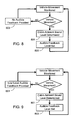
- Fig. 9 illustrates an alternate methodology for use with the interface shown in Fig. 7 ;
- Fig. 10 illustrates a block diagram of an interface using adaptive soft buttons
- Fig. 11 illustrates the same user interface as shown in Fig. 3 , but adapted to compensate for worsening driving conditions
- Fig. 12 illustrates the same user interface as shown in Fig. 11 , except that the extended touch-sensitive region of each soft button is visible to the user;
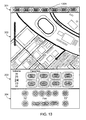
- Fig. 13 illustrates the same user interface as shown in Fig. 11 , except that the touch-sensitive regions have been extended sufficiently to cause an overlap of some soft buttons;
- Fig. 14 illustrates a particular interface zone in its non-adapted configuration, i.e., configured for optimal interface use
- Fig. 15 illustrates the interface zone shown in Fig. 14 , adapted to compensate for non-optimal interface operating conditions
- Fig. 16 illustrates the interface zone shown in Fig. 15 , adapted to compensate for a further deterioration in interface operating conditions
- Fig. 17 illustrates a block diagram of a vehicle user interface that determines the controls that are displayed based on vehicle operating conditions
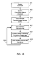
- Fig. 18 illustrates the methodology for use with the interface shown in Fig. 17 ;
- Fig. 19 illustrates a user interface that has been modified in response to detecting a change in precipitation levels
- Fig. 20 illustrates a user interface similar to that shown in Fig. 3 ;
- Fig. 21 illustrates the user interface of Fig. 20 after the system controller determines that the vehicle is in close proximity to the user's home.
- External vehicle conditions that are primarily outside the control of the user include lighting (e.g., day time, night time, night time with nearby high intensity city lighting, night time with little or no additional lighting, etc.), audio levels (e.g., road noise, wind noise, nearby construction, etc.), weather (e.g., rain, fog, snow, sleet, etc.) and driving conditions (e.g., paved road, gravel road, bumpy road, windy road, etc.).
- External vehicle conditions that are at least partially under the control of the driver include road selection and driving speed for a given set of road conditions. To a large extent, conditions within the vehicle are under the control of the driver, such conditions including lighting (e.g., passenger compartment lighting) and audio levels (e.g., volume levels for the vehicle's entertainment system).
- the present invention provides a means for a vehicle user interface to actively adapt to changing conditions, thereby providing the user with a safer, more intuitive, easier-to-use interface regardless of the conditions in which the driver and/or passenger finds themselves.
- each aspect of the vehicle user interface also referred to herein as simply the user interface, is optimized assuming few, if any, distractions.
- exemplary distractions include non-optimal lighting, driving conditions, weather, noise, etc.
- the system of the invention is designed to monitor some, or all, of these conditions and vary the interface in response to the monitored conditions. For clarity, in the following description each of these conditions and the preferred way in which the user interface adapts to the monitored condition is discussed individually. It should be appreciated, however, that a single interface may be configured to adapt to multiple changing conditions.
- Fig. 1 is a block diagram of the primary subsystems and components involved in a preferred embodiment of the invention for use in a vehicle. While the intended vehicle is preferably a car, and more preferably an electric or hybrid car, it will be appreciated that the present invention can be used, and is useful, in any vehicle in which the driver and/or passenger maybe subjected to varying audio, visual or tactile distractions while attempting to operate the vehicle's user interface. Accordingly, in addition to automobiles, the present invention may be used with motorbikes, boats, planes, off-road vehicles, etc. Additionally, it will be appreciated that other system configurations may be utilized while still retaining the functionality of the present invention. Lastly, it should be understood that one or more of the elements shown in Fig. 1 can be grouped together in a single device, and/or circuit board, and/or integrated circuit.
- system 100 includes a user interface 101.
- user interface 101 is shown as a single interface, for example, a single touch-screen as preferred, it should be understood that interface 101 may be comprised of multiple interfaces (e.g., multiple touch-screens, each configured to provide the user with an interface for one or more specific vehicle subsystems). Additionally, interface 101 may include a single type of interface, or multiple interface types (e.g., audio and visual).
- controller 103 couples to user interface 101 to a system controller 103.
- controller 103 includes a graphical processing unit (GPU) 105, a central processing unit (CPU) 107, and memory 109.
- CPU107 and GPU 105 may be separate or contained on a single chip set.
- Memory 109 may be comprised of EPROM, EEPROM, flash memory, RAM, a solid state disk drive, a hard disk drive, or any other memory type or combination of memory types.
- Controller 103 may be separate from, or integrated with, user interface 101.
- Coupled to controller 103 are one or more condition sensors 111, sensors 111 configured to monitor the conditions in question.
- sensors 111 may include one or more of audio sensors, light sensors, accelerometers, velocity sensors, temperature sensors, etc.
- Fig. 2 illustrates the basic methodology of the invention.
- the first step is to initiate system operation (step 201). Typically this step occurs when the user turns on the vehicle, for example by turning a key to the "on” position, pressing the vehicle “on” button, or otherwise initiating vehicle operation.
- the vehicle may go through an internal system check in which the operational status of one or more vehicle subsystems will be determined in order to insure that the vehicle is ready for operation (step 203).
- the user interface may or may not display various messages to the user, for example notifying the user of the operational status of the vehicle and/or various vehicle subsystems (step 205).
- the user interface is set (step 207), for example displaying various subsystem information and controls based on a predefined format.
- the predefined format may be preset by the vehicle manufacturer, by a service representative of the vehicle manufacturer, by the user, or by a third party (e.g., technician).
- the user interface displays information, and interacts with the driver and/or passenger, based on optimal operating conditions, e.g., the vehicle parked with minimal audible, visual or tactile distractions.
- the system periodically monitors vehicle operating conditions (209) using one or more sensors as previously noted and as described in detail below.
- the frequency of monitoring step 209 may be on the order of minutes, seconds, milliseconds, or some other time period. Additionally, the system may be set-up to monitor different operating conditions with different frequencies.
- weather conditions e.g., precipitation and/or ambient temperature, etc.
- road conditions e.g., incline, road bumpiness, etc.
- driving conditions e.g., vehicle speed, steering wheel position, etc.
- the system may also be set-up to monitor conditions using a threshold-based system, i.e., where certain conditions will trigger changes with the user interface.
- the system may have an audio volume threshold level for inside the passenger cabin, and/or one or more speed thresholds, etc.
- the results of monitoring step 209 are compared to a preset set of operating conditions. If the interface operating conditions remain optimal, or within a range deemed optimal, then the system loops back (step 211) and continues to monitor conditions. If the interface operating conditions are determined to be sufficiently changed (step 213) to warrant one or more changes to the user interface, then interface operating conditions must be categorized (step 215). In this step, the severity of the interface operating condition(s) is determined. Typically step 215 is implemented using a look-up table.
- a vehicle speed of 0-15 MPH may be categorized as level 0 (e.g., optimal); 15-30 MPH categorized as level 1; 30-60 MPH categorized as level 2; 60-80 MPH categorized as level 3; and anything above 80 MPH as level 4, where increasing level corresponds to decreasing interface operating conditions.
- system controller implements an algorithm that determines the category based on all of the monitored conditions combined. For example, while a vehicle speed of 15-30 MPH may equate to level 1, and light precipitation may equate to level 1, the combination of a vehicle speed of 15-30 MPH with light precipitation may equate to level 2. Similarly, while executing a turn with a turning radius of 50 feet may equate to a level 1, the combination of a vehicle speed of 15-30 MPH with light precipitation while turning with a turning radius of 50 feet may equate to a level 3.
- step 217 the output of this step is compared to a preset set of interface configurations.
- This step is typically performed using a look-up table, for example stored in memory 109, where each possible operating condition category corresponds to a specific set of interface adaptations.
- the appropriate set of interface adaptations is then implemented (step 219). Loop 221 insures that throughout vehicle operation, the system is continually being updated, thereby insuring that the appropriate user interface settings are used.
- the user interface is capable of a variety of interface adaptations, the extent of these adaptations being dependent upon the level of deterioration of the interface operating conditions.
- the interface is capable of only two settings; optimal and non-optimal. In the optimal configuration it is assumed that there are few, if any, driver/passenger distractions, thus allowing the user to devote their attention to accessing and using the vehicle interface.
- the non-optimal configuration is used when the driver/passenger may be distracted due to road conditions, weather conditions, etc., regardless of the severity of these distractions.
- Fig. 3 illustrates an exemplary touch-screen 300, although it should be understood that an interface for use with the invention is not limited to this screen configuration and/or controls, and that interface 300 is only intended to illustrate a possible set of controls and interface configuration.
- Touch-screen 300 is preferably divided into multiple zones, each zone directed at a particular subsystem interface.
- a detailed description of a configurable, multizone touch-screen interface is given in co-pending U.S. Patent Application Serial No. 12/708,547, filed February 19, 2010 , the disclosure of which is incorporated herein for any and all purposes.
- touch-screen 300 the display is divided into four zones 301-304. Touch-screen 300 may, however, be divided into a fewer, or greater, number of zones. As shown, uppermost zone 301 is comprised of one or more soft buttons 305. Soft buttons 305 may be used to provide the user with access to general display control settings. Alternately, soft buttons 305 may be configured to provide the user with rapid access to frequently used interface functions, for example, direct access to specific subsystems (e.g., general set-up, climate control subsystem, audio subsystem, mobile/cell phone interface, navigation subsystem, drive train monitoring interface, battery charging subsystem interface, web browser, back-up and/or forward view camera, etc.).
- specific subsystems e.g., general set-up, climate control subsystem, audio subsystem, mobile/cell phone interface, navigation subsystem, drive train monitoring interface, battery charging subsystem interface, web browser, back-up and/or forward view camera, etc.
- zone 301 may be used to display system information, e.g., status of various subsystems, etc.
- a soft button refers to a pre-defined, touch-sensitive region of display 300 that activates or otherwise controls a function in a manner similar to that of a hard button (i.e., a toggle switch, a push button, etc.).
- a hard button i.e., a toggle switch, a push button, etc.
- the screen in addition to zone 301, the screen includes a navigation zone 302, an entertainment zone 303, and a passenger cabin climate control zone 304. It will be appreciated that these zones may be of different size and proportions than shown, and may be configured to display other subsystem information (e.g., a web browser) than shown.
- Each zone includes various controls that correspond to the displayed subsystem.
- navigation zone 302 may include address input controls, zoom controls, route controls, etc.
- entertainment zone 303 may include volume controls, input selection controls, broadcast station controls, tone controls, etc.
- climate control zone 304 may include temperature controls, fan controls, defroster controls, vent controls, etc.
- the present invention simplifies user/interface interaction by altering various aspects of the interface as ambient and vehicle conditions change.
- aspects of the vehicle interface that change depend, at least in part, on the configuration of the vehicle interface as well as the capabilities of the vehicle itself.
- the user is able to set-up the ways in which the user interface adapts to changingambient and vehicle conditions.
- This form of customization allows the system to be adapted to match the particular preferences and capabilities of the end user which may vary depending upon driver/user age, reflexes, training, etc.
- the user When a vehicle is parked, the user (driver/passenger) is able to devote their full attention to the vehicle's user interface, specifically looking at the interface as they modify or adjust the controls (e.g., cabin heating/cooling/ventilation system, entertainment system, etc.).
- the controls e.g., cabin heating/cooling/ventilation system, entertainment system, etc.
- the driver when the vehicle is moving, the driver, and to a limited extent the passenger, must focus a large portion of their visual attention on the task of driving, in particular traffic conditions, road conditions, direction of travel, other vehicles, etc.
- the vehicle when the vehicle is moving the user is no longer able to rely as strongly, nor for extended periods of time, on visual cues when interacting with the interface.
- the system includes a vehicle speed sensor 401.
- Vehicle speed sensor 401 may be a transmission/gear sensor that senses whether the vehicle is in park or drive. Alternately, speed sensor 401 may sense vehicle movement, for example by monitoring motor, wheel or axle rotation.
- user interface 101 When the vehicle is not moving (step 501) as sensed by sensor 401 and determined by system controller 103, preferably user interface 101 does not utilize audible feedback when the user inputs data via user interface 101 (step 503).
- the interface adapts to this change in condition by providing the user with an audible feedback cue (step 507) via a speaker 403 when a soft button is pressed (e.g., soft button 307).
- the audible feedback cue may be a click, tone, or other audible sound.
- the audible feedback cue may be a click, tone, or other audible sound.
- the system uses the vehicle's audio entertainment system, more specifically the speakers associated with the entertainment system, for speaker 403.
- speaker 403 may be a dedicated speaker.
- the user interface always provides audible feedback cues (step 601) when user input is registered, i.e., when a soft button is touched.
- the volume level of the audible feedback cue increases (step 603).
- the system allows the user to set the feedback volume levels for both vehicle conditions, i.e., non-movement and movement.
- vehicle movement is used as the condition that controls the audio feedback level
- sensor 401 simply senses whether or not the vehicle is in park. If the vehicle is not in park, i.e., it is in a forward or reverse gear, then audible feedback is provided to the user, or a higher feedback volume level is used, during interface interaction.
- the system may provide audible feedback at a predetermined speed rather than the onset of any vehicle movement.
- the user, vehicle manufacturer, or third party may set the speed at which audible feedback (or a higher volume level for the feedback) is provided to the user during interface interaction.
- the speed may be 5 MPH, 10 MPH, 20 MPH, 30 MPH or any other preselected speed.
- This embodiment of the system is based on the assumption that at very low speeds the user is still able to devote sufficient attention to the interface to not require audible feedback, and as such, audible feedback is only needed at higher vehicle speeds when the user is distracted.
- the system in addition to a speed sensor 401, also includes a sensor 701 that monitors the sound level within the vehicle's passenger cabin.
- Speed sensor 401 operates as previously described, i.e., monitoring vehicle speed using a gear sensor (e.g., 'park' versus 'drive'), motor rotation speed sensor, wheel rotation speed sensor, axle rotation speed sensor, etc., to determine whether the vehicle is moving and/or at what speed the vehicle is moving.
- Sensor 701 is used to set the volume level of the audible feedback, thus insuring that the feedback volume is of sufficient volume to be easily heard by the user during interface interaction.
- Figs. 8 and 9 illustrate the methodology used with the interface shown in Fig. 7 , with and without low level audible feedback being provided when the vehicle is parked.
- the system controller determines the sound level within the vehicle cabin (step 801). Then the system controller sets the volume level for interface feedbackto a level sufficient to be heard over the pre-existing sounds within the vehicle (step 803). This embodiment insures that regardless of the ambient sound level, the user will still be able to effectively interact with user interface 101.
- each soft button is defined, in part, by the area of the touch-sensitive region provided for that control on the interface.
- the touch-sensitive region may or may not be the same size as the graphic that is displayed on the interface that represents the soft button.
- the touch-sensitive region for each soft button associated with the 'Favorites' section of the entertainment zone 303 is illustrated by a shaded portion.
- the volume control in zone 303 does not include any shading.
- volume control may be configured to accept tapping input (i.e., tapping on a volume level to select that level and/or tapping above or below the center number to increase/decrease the volume level) and/or to accept a sliding (or swiping) gesture up/down to alter the volume level.
- tapping input i.e., tapping on a volume level to select that level and/or tapping above or below the center number to increase/decrease the volume level
- a sliding (or swiping) gesture up/down to alter the volume level.
- a 'tap' speed associated with each soft button, this speed defining the length of time that the user's finger must be pressed against the soft button in order to register a 'touch'.
- the tap speed is used to distinguish between intentional and accidentalbutton touches.
- This aspect of the invention recognizes that the user has much more control over their interaction with the soft buttons during times of minimal distraction. For example, when the vehicle is parked or traveling at low speeds, the user is able to accurately touch a relatively small region of the screen, and to touch this area at a relatively high tap speed. In contrast, when the user is distracted due to road conditions, or the road conditions are poor (e.g., bumpy road), the user may find it difficult to accurately touch a small region of the screen, and/or to do so at a relatively high tap rate.
- system controller 103 is coupled to one or more of a vehicle vibration sensor 1001, a vehicle cornering sensor 1002, and a vehicle speed sensor 1003.
- System controller 103 may also be coupled to a precipitation sensor 1004 and to an ambient external temperature sensor 1005. While other sensors may be used to sense other vehicle conditions, the inventors have found that the above-identified sensors, or some subset thereof, are adequate to use to adapt the vehicle interface to changing conditions. Each of these sensors will now be described in further detail.
- Vibration sensor 1001 monitors the amount of vibration that is transmitted from the road, or from the drive train, to the passenger cabin where the driver/passenger and the user interface are located. As the degree to which road bumpiness and drive train operation impacts the user depends on the various vehicle isolation systems that are used to isolate the cabin from external vibrations (e.g., shock absorbers, vibration isolators, etc.), it will be appreciated that sensor(s) 1001 must be mounted within the passenger cabin, or in a location that experiences the same level of vibration as the passenger cabin. Vibration sensor 1001 is important in this embodiment of the invention as cabin vibrations make it very difficult for the user to accurately touch a specific spot on the interface, and to do so at a relatively high tap rate.
- Vibration sensor 1001 is important in this embodiment of the invention as cabin vibrations make it very difficult for the user to accurately touch a specific spot on the interface, and to do so at a relatively high tap rate.
- Cornering sensor 1002 monitors when, and to what degree, the vehicle is driving around a corner. Cornering sensor 1002 may monitor steering wheel position, wheel position, lateral force, or some combination of these qualities. Sensing vehicle cornering is important for several reasons. First, during vehicle cornering, the user is moving the steering wheel away from the neutral position, where the neutral position is defined as the steering wheel position that allows the vehicle to move forward or backward in a straight line. As a result, at least one of the driver's hands is busy moving and controlling the steering wheel. Second, during cornering the driver's attention is primarily directed at the task of cornering, not the task of interacting with the user interface.
- lateral force is applied to the driver and the passenger, making it more difficult to accurately touch a position on the interface touch-screen.
- the greater the lateral force the greater the difficulty in user-interface interaction.
- the amount of lateral force depends upon both the vehicle speed and the turn radius.
- sensor 1002 is not utilized.
- the reason for not including a cornering sensor of any type is that in most situations, the driver will not attempt to utilize the user interface during a cornering maneuver, or when the car is experiencing lateral forces without cornering (i.e., during a slide). In some embodiments, however, sensor 802 is included since even during cornering the passenger may still wish to input or otherwise control various vehicle subsystems using the screen interface.
- the system includes a vehicle speed sensor 1 003that monitors vehicle speed, for example by monitoring motor rotational speed, wheel rotational speed, or axle rotational speed.
- System controller 103 converts the monitored rotational speed to a vehicle speed.
- precipitation sensor 1004 may simply sense precipitation that exceeds a preset level, preferably sensor 1004 is able to sense the level of precipitation, thus allowing the system to more accurately adapt the user interface to changing weather conditions.
- system controller 103 is able to determine the likelihood of snowy, or icy, driving conditions, based on the monitored external temperature.
- the present system adapts the soft buttons to the new vehicle conditions.
- the ways in which the soft buttons adapt may be visible to the user, or completely transparent to the user. In general, transparency is preferred in order to minimize the risk of distracting the user by varying the look of the interface.
- Fig. 11 illustrates the same user interface as shown in Fig. 3 , but adapted to compensate for worsening driving conditions.
- the touch area corresponding to each soft button has been significantly increased, thereby making it easier for the user to touch the desired soft button.
- the extended touch sensitive region for each soft button indicated by shaded region 1101
- the user would see the same interface as shown in Fig. 3 , but the interface would accept button touches over a much larger region, i.e., region 1101 for each button, than indicated by the displayed button graphics. This allows the user to quickly utilize the user interface, and for the user interface to accurately recognize the user's intended touches, even if the user misses the intended soft button by a small amount.
- Fig. 12 illustrates an alternate embodiment in which the touch sensitive region of each soft button has been extended as described above relative to interface 1100, but without the transparency aspects. Therefore in this embodiment the extended button size 1201 is visible to the user as shown. While this approach may be more distracting than the transparent approach described above, it has the advantage of showing the user the actual touch sensitive regions.
- the soft buttons may be close enough together on the optimum settings (e.g., Fig. 3 ) that extending the touch region during interface adaptation causes an overlap of the touch-sensitive region of adjacent soft buttons as illustrated by overlapping region 1301 of Fig. 13 .
- a simple proximity-based algorithm is applied by system controller 103 to determine the intended soft button. More specifically, if the user presses a region where two touch-sensitive regions overlap (e.g., region 1301 in Fig. 13 ), the system controller compares the distance between the center of the area touched by the user and the center of each of the two soft buttons that include that touch-sensitive region. The soft button with the shortest distance to the center of the touched region is selected by controller 103 as the likely target of the user. Preferably when the touch region is extended to such a degree that it overlaps with adjacent touch regions, the extended touch regions are transparent as described above relative to Fig. 11 , thereby minimizing user confusion and distraction.
- the present invention may also be used to adapt tap frequency/duration requirements.
- the interface when the conditions are optimal, the interface may be configured to only require a tap duration of 0.1 seconds, thus allowing the user to quickly tap the desired control soft button. As conditions worsen, the interface may be configured to increase the time that the user must touch a specific soft button before that touch is recognized by the system controller as a legitimate touch. Therefore in this example, the tap duration may be extended from 0.1 to 0.5 seconds when the driving conditions deteriorate.
- the touch sensitive region of a soft button, and/or the tap duration may be varied incrementally over a range of conditions, or that the system may be configured to differentiate between only two conditions, i.e., optimal and non-optimal.
- An exemplary system in which multiple configurations are utilized over a range of conditions is illustrated in Figs. 14-16 , these figures illustrating three different adaptations of zone 303 of interface 300. It should be understood that these figures are only meant to illustrate various degrees of interface adaptation, and therefore the degree to which the touch sensitive regions or the tap durations change should not be considered as limits or best mode configurations.
- interface zone 303 is shown in its non-adapted configuration, i.e., configured for optimal interface use.
- a tap duration 'x' e.g., 0.2 seconds
- Fig. 15 shows the same zone adapted to compensate for non-optimal interface operating conditions.
- each soft button 1501 has an enlarged touch sensitive region 1503.
- volume slide control 1401 has an extended touch sensitive region 1505.
- Tap duration has been increased to 2x, e.g., to 0.4 seconds.
- the touch sensitive region for each button 1501 and the slide control 1401 further expand as illustrated by regions 1601 and 1603, respectively, shown in Fig. 16 .
- the tap duration also increases to 2.5x, e.g., to 0.5 seconds. Note that while these figures illustrate a transparent approach to the extended touch sensitive regions, as described above relative to Fig. 11 , a non-transparent approach such as that illustrated in Fig. 12 is similarly applicable.
- the system is preferably configured to adapt the user interface in such a way that the combination of driving, road and weather conditions is taken into account.
- a touch-screen interface In a typical vehicle interface, the controls associated with each represented vehicle subsystem are predefined, either by the vehicle manufacturer, by a service representative of the vehicle manufacturer, by the user, or by a third party (e.g., technician).
- a third party e.g., technician
- the controls that are provided on the interface are determined, at least in part, by current vehicle conditions. As such, the interface is able to show those controls that are most likely to be of interest to the driver/passenger, while eliminating controls that are of minimal, if any, use to the driver/passenger given the present conditions.
- Fig. 17 and 18 illustrate an exemplary system and methodology, respectively, which demonstrate this aspect of the invention.
- the system operates in a similar fashion as previously described relative to Fig. 2 , including step 207 in which the interface is initially set-up as previously configured by the user, service technician, manufacturer, etc.
- system controller 103 obtains current vehicle status from a variety of sensors, e.g., sensors 1701-1707 (step 1801). It will be appreciated that these sensors may be the same sensors as used with other aspects of the invention, or a different set of sensors, or some subset thereof.
- system controller 103 determines whether modifications of the interface should be made (step 1803).
- the types of modifications made by system controller 103, as well as the thresholds necessary to implement these modifications may be set-up by the user, the vehicle's manufacturer, a service representative of the vehicle's manufacturer, or a third party. Exemplary interface modifications are described below.
- the controls necessary to turn on/off the windshield wipers as well as vary the windshield wiper speed are always present.
- these controls would be represented by soft buttons on interface 101.
- precipitation sensor 1701 determines dry conditions, these controls would not appear on interface 101, thus eliminating a distraction to the driver. Additionally, by eliminating these controls when the system deems them unnecessary, space is freed up on the interface that may be used for other controls, or simply to provide more space for the other subsystems.
- system controller 103 reconfigures the interface to include the controls necessary to operate the windshield wipers. For example, Fig.
- Interface 19 shows an interface 1900, similar to interface 300, for use when the system determines that wet driving conditions are present.
- Interface 1900 includes various wiper controls, e.g., wiper on soft button 1901, wiper off soft button 1903, wiper speed soft buttons 1905, and wiper intermittent control soft buttons 1907 and 1909. If desired, the wipers may be configured to turn-on at some pre-selected wiper speed when precipitation is first detected.
- the controls presented on the user interface depend upon the number of occupants within the vehicle. Although a variety of techniques may be used to determine the number, and location, of the occupants, preferably pressure sensitive switches 1707 are mounted within the car seats and used to determine the number and location of the vehicle's passengers. Using this information, the information displayed on the user interface may be varied. For example, while interface 300 includes dual temperature controls, i.e., a driver temperature control 309 and a passenger temperature control 311, the system may adapt to only having the driver present by only displaying control 309 and eliminating control 311. Other interface adaptations based on the number of vehicle passengers are envisioned, for example, displaying seat adjustment controls on the interface, but only for those seats containing passengers.
- This functionality is included as a convenience to the user, allowing the user to activate these external systems without requiring them to carry a separate controller (e.g., a garage door opener) or to leave the confines of their vehicle when they activate the external system.
- a separate controller e.g., a garage door opener
- a relatively low power RF transmitter within the vehicle transmits the necessary signal to activate the desired device, the RF transmitter preset for a specific frequency and/or utilizing a preset code.
- buttons that represent these features are only present when system controller 103 determines that the vehicle is in close proximity to the location where control is desired (e.g., the user's home). System controller 103 determines this proximity using data from GPS system 1703 along with preset 'home' coordinates.
- Figs. 20 and 21 illustrate this aspect of the invention, Fig. 20 showing an interface similar to interface 300 except for the lack of soft buttons within zone 301.
- the interface changes as shown in Fig. 19 , this interface including three soft buttons 1901-1903 within zone 301 labeled, respectively, "Garage 1", “Garage 2" and "Home Lights".
- the user is able to label these three buttons as desired, and thus the indicated labels are only for illustration purposes. It will be appreciated that a fewer, or greater, number of such soft buttons may be included on the interface without departing from the invention.
- the interface adapts to the style of driving, and more specifically, adapts to an aggressive style of driving versus a non-aggressive style of driving.
- the interface adapts, for example by altering the controls and displays shown on the interface.
- the vehicle may include a pair of interfaces, one positioned approximately between the driver's seat and the front passenger seat, and the other interface positioned directly in front of the driver, this interface providing driver centric display information (e.g., speedometer, engine/motor temperature, battery state-of-charge, tachometer, etc.).
- aggressive driving may be determined using any of several techniques (e.g., monitoring vehicle speed, vehicle acceleration, lateral force, etc.). For example, system controller 103 may make this determination based on vehicle speed alone as provided by sensor 1704 or in concert with lateral motion sensor 1705, sensor 1705 providing a measure of lateral force that may result from hard cornering. Alternately, system controller 103 may make this determination by monitoring a performance mode switch that allows the driver to select between at least a 'normal' driving mode and a 'performance' driving mode. Selection of the 'performance' mode may only change attributes of the interface, or it may change other aspects of the vehicle as well, for example the set-up of the suspension system.
- a performance mode switch that allows the driver to select between at least a 'normal' driving mode and a 'performance' driving mode. Selection of the 'performance' mode may only change attributes of the interface, or it may change other aspects of the vehicle as well, for example the set-up of the suspension system.
- the interface (or interfaces if the vehicle utilizes multiple configurable interfaces) is adapted to minimize non-essential displays and controls, thereby minimizing driver distractions.
- the non-essential displays/controls may be preset by the manufacturer, preferably the user makes this determination.
- minimization of non-essential displays/controls simply means dimming the display brightness for these aspects of the interface (e.g., the media controls, climate controls, etc.) relative to the essential interface elements (e.g., speedometer, etc).
- the display interface for non-essential vehicle subsystems may be simplified, for example by including a subset of the controls that allows the user limited subsystem control while minimizing interface distractions.
- the audio entertainment subsystem zone 303 of interface 300 may be changed to only show the volume control.
- one or more display elements or controls of non-essential subsystems are altogether eliminated from the user interface.
- the interface(s) is adapted to highlight those controls that the driver is likely to require or use during this driving period, for example the speedometer, engine/motor temperature, lap timer, battery state-of-charge gauge, tachometer, etc.
- the displays and/or controls that are highlighted in this driving mode may be highlighted by increasing the display brightness for these displays/controls relative to non-essential displays/controls.
- the size of the affected displays/controls may be increased to highlight their significance relative to the non-essential interface elements.
Landscapes
- Engineering & Computer Science (AREA)
- General Engineering & Computer Science (AREA)
- Theoretical Computer Science (AREA)
- Transportation (AREA)
- Mechanical Engineering (AREA)
- Chemical & Material Sciences (AREA)
- Combustion & Propulsion (AREA)
- Human Computer Interaction (AREA)
- Physics & Mathematics (AREA)
- General Physics & Mathematics (AREA)
- User Interface Of Digital Computer (AREA)
- Position Input By Displaying (AREA)
- Navigation (AREA)
- Lighting Device Outwards From Vehicle And Optical Signal (AREA)
- Fittings On The Vehicle Exterior For Carrying Loads, And Devices For Holding Or Mounting Articles (AREA)
Applications Claiming Priority (4)
| Application Number | Priority Date | Filing Date | Title |
|---|---|---|---|
| US27833709P | 2009-10-05 | 2009-10-05 | |
| US12/708,547 US8078359B2 (en) | 2009-10-05 | 2010-02-19 | User configurable vehicle user interface |
| US12/725,391 US9079498B2 (en) | 2009-10-05 | 2010-06-16 | Morphing vehicle user interface |
| US12/868,551 US20110082620A1 (en) | 2009-10-05 | 2010-08-25 | Adaptive Vehicle User Interface |
Publications (2)
| Publication Number | Publication Date |
|---|---|
| EP2305505A2 true EP2305505A2 (de) | 2011-04-06 |
| EP2305505A3 EP2305505A3 (de) | 2011-08-10 |
Family
ID=43528585
Family Applications (1)
| Application Number | Title | Priority Date | Filing Date |
|---|---|---|---|
| EP10013330A Withdrawn EP2305505A3 (de) | 2009-10-05 | 2010-10-05 | Adaptive Softbuttons für eine Fahrzeugbenutzerschnittstelle |
Country Status (3)
| Country | Link |
|---|---|
| US (1) | US20110082620A1 (de) |
| EP (1) | EP2305505A3 (de) |
| JP (1) | JP5216829B2 (de) |
Cited By (16)
| Publication number | Priority date | Publication date | Assignee | Title |
|---|---|---|---|---|
| WO2015088426A1 (en) * | 2013-12-09 | 2015-06-18 | Scania Cv Ab | Method and system for facilitating the selection of control devices from a set of control devices for vehicle functions |
| WO2015090505A1 (de) * | 2013-12-21 | 2015-06-25 | Audi Ag | Sensorvorrichtung und verfahren zum erzeugen von wegezustandsabhängig aufbereiteten betätigungssignalen |
| EP2715494A4 (de) * | 2011-05-30 | 2015-09-09 | Li Ni | Graphikobjektauswahl mittels gerichteter wischgesten |
| WO2015131554A1 (zh) * | 2014-09-22 | 2015-09-11 | 中兴通讯股份有限公司 | 一种屏幕亮度调节的方法、装置及电子设备 |
| GB2524937A (en) * | 2013-07-01 | 2015-10-14 | Continental Automotive Systems | Simple and reliable home location identification method and apparatus |
| WO2016147174A1 (en) * | 2015-03-13 | 2016-09-22 | Project Ray Ltd | System and method for adapting the user-interface to the user attention and driving conditions |
| CN106020856A (zh) * | 2015-03-30 | 2016-10-12 | 福特全球技术公司 | 用于车辆特征配置的方法和系统 |
| CN106740590A (zh) * | 2016-11-28 | 2017-05-31 | 北京汽车研究总院有限公司 | 一种汽车网络控制方法及装置 |
| CN107010042A (zh) * | 2015-10-22 | 2017-08-04 | 福特全球技术公司 | 用来检测停放的车辆是处于封闭空间还是开放空间的系统和方法 |
| CN108304244A (zh) * | 2018-02-24 | 2018-07-20 | 北京车和家信息技术有限公司 | 车载系统界面展示的方法及装置 |
| CN109177984A (zh) * | 2018-09-04 | 2019-01-11 | 重庆长安汽车股份有限公司 | 车载显示设备主题的控制方法和控制装置 |
| US10351009B2 (en) | 2015-07-31 | 2019-07-16 | Ford Global Technologies, Llc | Electric vehicle display systems |
| CN110045848A (zh) * | 2017-11-17 | 2019-07-23 | 乐金显示有限公司 | 触摸屏装置和包括触摸屏装置的电子设备 |
| CN111661063A (zh) * | 2019-11-18 | 2020-09-15 | 摩登汽车有限公司 | 电动汽车的人车交互系统及电动汽车 |
| DE102015116321B4 (de) | 2014-09-29 | 2024-02-01 | Ford Global Technologies, Llc | Fahrzeug, Fahrzeugsystem und Verfahren zur Assistenz bei einem unerwarteten thermischen Ereignis |
| EP4343524A1 (de) * | 2022-09-22 | 2024-03-27 | Schneider Electric Industries Sas | Industrieller berührungsbildschirm |
Families Citing this family (58)
| Publication number | Priority date | Publication date | Assignee | Title |
|---|---|---|---|---|
| DE102008029446B4 (de) * | 2008-06-20 | 2024-08-08 | Bayerische Motoren Werke Aktiengesellschaft | Verfahren zur Steuerung von Funktionen in einem Kraftfahrzeug mit benachbart liegenden Bedienelementen |
| US8725330B2 (en) | 2010-06-02 | 2014-05-13 | Bryan Marc Failing | Increasing vehicle security |
| US20120144299A1 (en) * | 2010-09-30 | 2012-06-07 | Logitech Europe S.A. | Blind Navigation for Touch Interfaces |
| TWI515603B (zh) * | 2011-03-28 | 2016-01-01 | 緯創資通股份有限公司 | 觸控反饋裝置、觸控反饋方法及觸控顯示裝置 |
| WO2013089012A1 (ja) * | 2011-12-14 | 2013-06-20 | 株式会社ソニー・コンピュータエンタテインメント | 情報処理装置、情報処理方法、プログラム及び情報記憶媒体 |
| DE102012005084A1 (de) | 2012-03-13 | 2013-09-19 | GM Global Technology Operations LLC (n. d. Gesetzen des Staates Delaware) | Eingabevorrichtung |
| DE102012005800A1 (de) | 2012-03-21 | 2013-09-26 | Gm Global Technology Operations, Llc | Eingabevorrichtung |
| US9219992B2 (en) * | 2012-09-12 | 2015-12-22 | Google Inc. | Mobile device profiling based on speed |
| US20150258996A1 (en) * | 2012-09-17 | 2015-09-17 | Volvo Lastvagnar Ab | Method for providing a context based coaching message to a driver of a vehicle |
| US9372538B2 (en) * | 2012-09-28 | 2016-06-21 | Denso International America, Inc. | Multiple-force, dynamically-adjusted, 3-D touch surface with feedback for human machine interface (HMI) |
| US8825234B2 (en) * | 2012-10-15 | 2014-09-02 | The Boeing Company | Turbulence mitigation for touch screen systems |
| JP6052865B2 (ja) * | 2012-10-29 | 2016-12-27 | アルパイン株式会社 | 車載表示制御装置および車載表示制御方法 |
| US9858809B2 (en) * | 2012-11-08 | 2018-01-02 | Qualcomm Incorporated | Augmenting handset sensors with car sensors |
| US8941344B2 (en) * | 2012-12-19 | 2015-01-27 | Chrysler Group Llc | Vehicle wiper control system and method |
| US9303997B2 (en) | 2013-03-15 | 2016-04-05 | Apple Inc. | Prediction engine |
| US9891068B2 (en) | 2013-06-08 | 2018-02-13 | Apple Inc. | Mapping application search function |
| US9317813B2 (en) | 2013-03-15 | 2016-04-19 | Apple Inc. | Mobile device with predictive routing engine |
| EP3101392B1 (de) * | 2013-03-15 | 2021-12-15 | Apple Inc. | Mapping-anwendung mit turn-by-turn-navigationsmodus zur ausgabe auf einer fahrzeuganzeige |
| EP2778615B1 (de) * | 2013-03-15 | 2018-09-12 | Apple Inc. | Mapping-Anwendung mit mehreren Benutzeroberflächen |
| US20140303839A1 (en) * | 2013-04-03 | 2014-10-09 | Ford Global Technologies, Llc | Usage prediction for contextual interface |
| US20140365459A1 (en) | 2013-06-08 | 2014-12-11 | Apple Inc. | Harvesting Addresses |
| KR101528518B1 (ko) * | 2013-11-08 | 2015-06-12 | 현대자동차주식회사 | 차량 및 그 제어방법 |
| DE102015206263A1 (de) * | 2014-04-10 | 2015-10-15 | Ford Global Technologies, Llc | Anwendungsvorhersage für kontextbezogene schnittstellen |
| CN105373299A (zh) * | 2014-08-25 | 2016-03-02 | 深圳富泰宏精密工业有限公司 | 电子装置及其显示界面调整方法 |
| US10066959B2 (en) | 2014-09-02 | 2018-09-04 | Apple Inc. | User interactions for a mapping application |
| KR20160031742A (ko) * | 2014-09-15 | 2016-03-23 | 현대자동차주식회사 | 차량 및 그 제어방법과 네비게이션 |
| EP3240715B1 (de) | 2014-12-30 | 2018-12-19 | Robert Bosch GmbH | Adaptive benützeroberfläche für ein autonomes fahrzeug |
| US10065502B2 (en) * | 2015-04-14 | 2018-09-04 | Ford Global Technologies, Llc | Adaptive vehicle interface system |
| US20170028850A1 (en) * | 2015-07-31 | 2017-02-02 | Ford Global Technologies, Llc | Vehicle display systems |
| US20170337027A1 (en) * | 2016-05-17 | 2017-11-23 | Google Inc. | Dynamic content management of a vehicle display |
| DK201770423A1 (en) | 2016-06-11 | 2018-01-15 | Apple Inc | Activity and workout updates |
| US11816325B2 (en) | 2016-06-12 | 2023-11-14 | Apple Inc. | Application shortcuts for carplay |
| BR112018075863A2 (pt) * | 2016-06-14 | 2019-03-19 | Nissan Motor Co., Ltd. | método de estimativa de distância entre veículos e dispositivo de estimativa de distância entre veículos |
| US20180121071A1 (en) * | 2016-11-03 | 2018-05-03 | Ford Global Technologies, Llc | Vehicle display based on vehicle speed |
| US10083640B2 (en) * | 2016-12-29 | 2018-09-25 | Pure Depth Limited | Multi-layer display including proximity sensor and depth-changing interface elements, and/or associated methods |
| US20180217717A1 (en) * | 2017-01-31 | 2018-08-02 | Toyota Research Institute, Inc. | Predictive vehicular human-machine interface |
| US10146390B1 (en) * | 2017-07-21 | 2018-12-04 | Cypress Semiconductor Corporation | Method of combining self and mutual capacitance sensing |
| CN108162811A (zh) * | 2017-12-15 | 2018-06-15 | 北京汽车集团有限公司 | 座椅控制方法及装置 |
| US10915101B2 (en) * | 2018-02-02 | 2021-02-09 | Uatc, Llc | Context-dependent alertness monitor in an autonomous vehicle |
| US20190246067A1 (en) * | 2018-02-06 | 2019-08-08 | GM Global Technology Operations LLC | Method and apparatus for activating forward view |
| JPWO2019239450A1 (ja) * | 2018-06-11 | 2021-02-12 | 三菱電機株式会社 | 入力制御装置、操作装置および入力制御方法 |
| RU192328U1 (ru) * | 2018-12-28 | 2019-09-12 | федеральное государственное бюджетное образовательное учреждение высшего образования "Московский государственный технический университет имени Н.Э. Баумана (национальный исследовательский университет)" (МГТУ им. Н.Э. Баумана) | Электронный блок автомобильных функций бортовой мультиплексной системы управления транспортным средством |
| RU193616U1 (ru) * | 2018-12-28 | 2019-11-07 | Александр Витальевич Уракаев | Многофункциональное измерительное устройство для двигателя внутреннего сгорания |
| US10817063B2 (en) * | 2019-02-11 | 2020-10-27 | Volvo Car Corporation | Facilitating interaction with a vehicle touchscreen using haptic feedback |
| US11626010B2 (en) * | 2019-02-28 | 2023-04-11 | Nortek Security & Control Llc | Dynamic partition of a security system |
| US20200279473A1 (en) * | 2019-02-28 | 2020-09-03 | Nortek Security & Control Llc | Virtual partition of a security system |
| FR3093963B1 (fr) * | 2019-03-22 | 2021-02-12 | Psa Automobiles Sa | Dispositif d’info-divertissement pour un véhicule |
| DE102019204216A1 (de) * | 2019-03-27 | 2020-10-01 | Volkswagen Aktiengesellschaft | Verfahren zum Betreiben einer berührungsempfindlichen Bedieneinrichtung eines Kraftfahrzeugs sowie Kraftfahrzeug zur Durchführung des Verfahrens |
| US11863700B2 (en) * | 2019-05-06 | 2024-01-02 | Apple Inc. | Providing user interfaces based on use contexts and managing playback of media |
| RU193218U1 (ru) * | 2019-08-23 | 2019-10-17 | Александр Витальевич Уракаев | Многофункциональное измерительное устройство для двигателя внутреннего сгорания |
| JP6877786B2 (ja) * | 2019-11-19 | 2021-05-26 | 株式会社ユピテル | システム及びプログラム |
| US11513604B2 (en) | 2020-06-17 | 2022-11-29 | Motorola Mobility Llc | Selectable response options displayed based-on device grip position |
| US11543860B2 (en) | 2020-07-30 | 2023-01-03 | Motorola Mobility Llc | Adaptive grip suppression tuning |
| US11595511B2 (en) | 2020-07-30 | 2023-02-28 | Motorola Mobility Llc | Adaptive grip suppression within curved display edges |
| US11508276B2 (en) | 2020-09-18 | 2022-11-22 | Motorola Mobility Llc | Adaptive user interface display size for curved display edges |
| US11287972B1 (en) * | 2020-09-18 | 2022-03-29 | Motorola Mobility Llc | Selectable element selection within a curved display edge |
| KR20220115001A (ko) * | 2021-02-09 | 2022-08-17 | 현대모비스 주식회사 | 스마트 디바이스 스위블을 이용한 차량 제어 장치 및 그 방법 |
| US11726734B2 (en) | 2022-01-13 | 2023-08-15 | Motorola Mobility Llc | Configuring an external presentation device based on an impairment of a user |
Family Cites Families (15)
| Publication number | Priority date | Publication date | Assignee | Title |
|---|---|---|---|---|
| US143884A (en) * | 1873-10-21 | Improvement in water-ejectors | ||
| US7489303B1 (en) * | 2001-02-22 | 2009-02-10 | Pryor Timothy R | Reconfigurable instrument panels |
| US9513744B2 (en) * | 1994-08-15 | 2016-12-06 | Apple Inc. | Control systems employing novel physical controls and touch screens |
| US6009355A (en) * | 1997-01-28 | 1999-12-28 | American Calcar Inc. | Multimedia information and control system for automobiles |
| US6275231B1 (en) * | 1997-08-01 | 2001-08-14 | American Calcar Inc. | Centralized control and management system for automobiles |
| FR2795796B1 (fr) * | 1999-06-29 | 2001-09-21 | Peugeot Citroen Automobiles Sa | Systeme de commande d'une boite de vitesses mecanique d'un vehicule automobile |
| DE19941973C5 (de) * | 1999-09-03 | 2012-05-16 | Volkswagen Ag | Verfahren und Vorrichtung zur aktiven Hilfestellung eines Kraftfahrzeugführers in einem Kraftfahrzeug |
| DE10153987B4 (de) * | 2001-11-06 | 2018-05-30 | Daimler Ag | Informationssystem in einem Fahrzeug |
| JP2003146055A (ja) * | 2001-11-12 | 2003-05-21 | Denso Corp | 車両用空調装置 |
| US7831319B2 (en) * | 2005-01-07 | 2010-11-09 | Gm Global Technology Operations, Inc. | Sensor based anticipatory lighting of controls |
| JP4609222B2 (ja) * | 2005-07-25 | 2011-01-12 | 株式会社デンソー | スイッチ装置 |
| US20070124043A1 (en) * | 2005-11-29 | 2007-05-31 | Ayoub Ramy P | System and method for modifying the processing of content in vehicles based on vehicle conditions |
| JP2008285046A (ja) * | 2007-05-18 | 2008-11-27 | Fujitsu Ten Ltd | 車載機器制御装置 |
| JP5073362B2 (ja) * | 2007-05-23 | 2012-11-14 | カルソニックカンセイ株式会社 | 車両用計器 |
| JP2009057013A (ja) * | 2007-09-03 | 2009-03-19 | Tokai Rika Co Ltd | 車両用タッチ検出機能付きスイッチ装置 |
-
2010
- 2010-08-25 US US12/868,551 patent/US20110082620A1/en not_active Abandoned
- 2010-10-04 JP JP2010224882A patent/JP5216829B2/ja active Active
- 2010-10-05 EP EP10013330A patent/EP2305505A3/de not_active Withdrawn
Cited By (19)
| Publication number | Priority date | Publication date | Assignee | Title |
|---|---|---|---|---|
| EP2715494A4 (de) * | 2011-05-30 | 2015-09-09 | Li Ni | Graphikobjektauswahl mittels gerichteter wischgesten |
| GB2524937A (en) * | 2013-07-01 | 2015-10-14 | Continental Automotive Systems | Simple and reliable home location identification method and apparatus |
| US9326100B2 (en) | 2013-07-01 | 2016-04-26 | Continental Automotive Systems, Inc. | Simple and reliable home location identification method and apparatus |
| WO2015088426A1 (en) * | 2013-12-09 | 2015-06-18 | Scania Cv Ab | Method and system for facilitating the selection of control devices from a set of control devices for vehicle functions |
| US10331279B2 (en) | 2013-12-21 | 2019-06-25 | Audi Ag | Sensor device and method for generating actuation signals processed in dependence on an underlying surface state |
| WO2015090505A1 (de) * | 2013-12-21 | 2015-06-25 | Audi Ag | Sensorvorrichtung und verfahren zum erzeugen von wegezustandsabhängig aufbereiteten betätigungssignalen |
| WO2015131554A1 (zh) * | 2014-09-22 | 2015-09-11 | 中兴通讯股份有限公司 | 一种屏幕亮度调节的方法、装置及电子设备 |
| DE102015116321B4 (de) | 2014-09-29 | 2024-02-01 | Ford Global Technologies, Llc | Fahrzeug, Fahrzeugsystem und Verfahren zur Assistenz bei einem unerwarteten thermischen Ereignis |
| WO2016147174A1 (en) * | 2015-03-13 | 2016-09-22 | Project Ray Ltd | System and method for adapting the user-interface to the user attention and driving conditions |
| CN106020856A (zh) * | 2015-03-30 | 2016-10-12 | 福特全球技术公司 | 用于车辆特征配置的方法和系统 |
| US10351009B2 (en) | 2015-07-31 | 2019-07-16 | Ford Global Technologies, Llc | Electric vehicle display systems |
| CN107010042A (zh) * | 2015-10-22 | 2017-08-04 | 福特全球技术公司 | 用来检测停放的车辆是处于封闭空间还是开放空间的系统和方法 |
| CN106740590A (zh) * | 2016-11-28 | 2017-05-31 | 北京汽车研究总院有限公司 | 一种汽车网络控制方法及装置 |
| CN110045848A (zh) * | 2017-11-17 | 2019-07-23 | 乐金显示有限公司 | 触摸屏装置和包括触摸屏装置的电子设备 |
| CN108304244B (zh) * | 2018-02-24 | 2021-12-28 | 北京车和家信息技术有限公司 | 车载系统界面展示的方法及装置 |
| CN108304244A (zh) * | 2018-02-24 | 2018-07-20 | 北京车和家信息技术有限公司 | 车载系统界面展示的方法及装置 |
| CN109177984A (zh) * | 2018-09-04 | 2019-01-11 | 重庆长安汽车股份有限公司 | 车载显示设备主题的控制方法和控制装置 |
| CN111661063A (zh) * | 2019-11-18 | 2020-09-15 | 摩登汽车有限公司 | 电动汽车的人车交互系统及电动汽车 |
| EP4343524A1 (de) * | 2022-09-22 | 2024-03-27 | Schneider Electric Industries Sas | Industrieller berührungsbildschirm |
Also Published As
| Publication number | Publication date |
|---|---|
| US20110082620A1 (en) | 2011-04-07 |
| JP2011081797A (ja) | 2011-04-21 |
| JP5216829B2 (ja) | 2013-06-19 |
| EP2305505A3 (de) | 2011-08-10 |
Similar Documents
| Publication | Publication Date | Title |
|---|---|---|
| EP2305506B1 (de) | Adaptive Softbuttons für eine Fahrzeugbenutzerschnittstelle | |
| EP2308713B1 (de) | Adaptive akustische Feedback-Hinweise für eine Fahrzeugbenutzerschnittstelle | |
| EP2305505A2 (de) | Adaptive Softbuttons für eine Fahrzeugbenutzerschnittstelle | |
| EP2305508B1 (de) | Benutzerkonfigurierbare Fahrzeugbenutzerschnittstelle | |
| JP5565421B2 (ja) | 車載操作装置 | |
| JP4130193B2 (ja) | 自動車のステアリングホイール | |
| US6418362B1 (en) | Steering wheel interface for vehicles | |
| EP2305507B1 (de) | Verwandlung einer Fahrzeugbenutzerschnittstelle | |
| EP2460694A1 (de) | Betriebssystem für ein fahrzeug | |
| EP2703226A1 (de) | Steuerungsvorrichtung und -programm für eine fahrzeugmontierte vorrichtung | |
| JP4779813B2 (ja) | 車両用操作装置 | |
| KR101558354B1 (ko) | 차량용 블라인드 콘트롤 시스템 | |
| JP4899488B2 (ja) | 車両用情報表示装置 | |
| KR101148981B1 (ko) | 스티어링휠에 설치된 차량용 제어장치 | |
| KR20090109605A (ko) | 차량의 스티어링 휠 장치 및 서비스 방법 | |
| KR102441509B1 (ko) | 단말기, 차량 및 단말기 제어방법 | |
| WO2019244812A1 (ja) | 車両用表示装置、車両用表示装置の制御方法、車両用表示装置の制御プログラム | |
| CN113733910A (zh) | 用于机动车辆的智能交互式控制系统 | |
| WO2024156343A1 (en) | Method and device for displaying content in vehicle | |
| KR101882202B1 (ko) | 사용자 인터페이스 장치, 이를 포함하는 차량 및 차량의 제어 방법 | |
| KR101657658B1 (ko) | 입력장치, 이를 포함하는 차량 및 그 제어방법 |
Legal Events
| Date | Code | Title | Description |
|---|---|---|---|
| PUAI | Public reference made under article 153(3) epc to a published international application that has entered the european phase |
Free format text: ORIGINAL CODE: 0009012 |
|
| AK | Designated contracting states |
Kind code of ref document: A2 Designated state(s): AL AT BE BG CH CY CZ DE DK EE ES FI FR GB GR HR HU IE IS IT LI LT LU LV MC MK MT NL NO PL PT RO RS SE SI SK SM TR |
|
| AX | Request for extension of the european patent |
Extension state: BA ME |
|
| PUAL | Search report despatched |
Free format text: ORIGINAL CODE: 0009013 |
|
| AK | Designated contracting states |
Kind code of ref document: A3 Designated state(s): AL AT BE BG CH CY CZ DE DK EE ES FI FR GB GR HR HU IE IS IT LI LT LU LV MC MK MT NL NO PL PT RO RS SE SI SK SM TR |
|
| AX | Request for extension of the european patent |
Extension state: BA ME |
|
| RIC1 | Information provided on ipc code assigned before grant |
Ipc: G06F 3/048 20060101ALI20110707BHEP Ipc: B60K 37/06 20060101AFI20110707BHEP |
|
| 17P | Request for examination filed |
Effective date: 20110902 |
|
| STAA | Information on the status of an ep patent application or granted ep patent |
Free format text: STATUS: THE APPLICATION IS DEEMED TO BE WITHDRAWN |
|
| 18D | Application deemed to be withdrawn |
Effective date: 20120211 |