EP2303426B1 - Composite filter media - Google Patents
Composite filter media Download PDFInfo
- Publication number
- EP2303426B1 EP2303426B1 EP09791095.4A EP09791095A EP2303426B1 EP 2303426 B1 EP2303426 B1 EP 2303426B1 EP 09791095 A EP09791095 A EP 09791095A EP 2303426 B1 EP2303426 B1 EP 2303426B1
- Authority
- EP
- European Patent Office
- Prior art keywords
- filter media
- composite filter
- accordance
- media structure
- nanofiber layer
- Prior art date
- Legal status (The legal status is an assumption and is not a legal conclusion. Google has not performed a legal analysis and makes no representation as to the accuracy of the status listed.)
- Active
Links
Images


Classifications
-
- B—PERFORMING OPERATIONS; TRANSPORTING
- B01—PHYSICAL OR CHEMICAL PROCESSES OR APPARATUS IN GENERAL
- B01D—SEPARATION
- B01D39/00—Filtering material for liquid or gaseous fluids
- B01D39/14—Other self-supporting filtering material ; Other filtering material
- B01D39/16—Other self-supporting filtering material ; Other filtering material of organic material, e.g. synthetic fibres
- B01D39/1607—Other self-supporting filtering material ; Other filtering material of organic material, e.g. synthetic fibres the material being fibrous
- B01D39/1623—Other self-supporting filtering material ; Other filtering material of organic material, e.g. synthetic fibres the material being fibrous of synthetic origin
- B01D39/163—Other self-supporting filtering material ; Other filtering material of organic material, e.g. synthetic fibres the material being fibrous of synthetic origin sintered or bonded
-
- B—PERFORMING OPERATIONS; TRANSPORTING
- B01—PHYSICAL OR CHEMICAL PROCESSES OR APPARATUS IN GENERAL
- B01D—SEPARATION
- B01D46/00—Filters or filtering processes specially modified for separating dispersed particles from gases or vapours
- B01D46/02—Particle separators, e.g. dust precipitators, having hollow filters made of flexible material
-
- B—PERFORMING OPERATIONS; TRANSPORTING
- B01—PHYSICAL OR CHEMICAL PROCESSES OR APPARATUS IN GENERAL
- B01D—SEPARATION
- B01D69/00—Semi-permeable membranes for separation processes or apparatus characterised by their form, structure or properties; Manufacturing processes specially adapted therefor
- B01D69/10—Supported membranes; Membrane supports
- B01D69/107—Organic support material
- B01D69/1071—Woven, non-woven or net mesh
-
- B—PERFORMING OPERATIONS; TRANSPORTING
- B01—PHYSICAL OR CHEMICAL PROCESSES OR APPARATUS IN GENERAL
- B01D—SEPARATION
- B01D69/00—Semi-permeable membranes for separation processes or apparatus characterised by their form, structure or properties; Manufacturing processes specially adapted therefor
- B01D69/12—Composite membranes; Ultra-thin membranes
- B01D69/1213—Laminated layers
-
- B—PERFORMING OPERATIONS; TRANSPORTING
- B01—PHYSICAL OR CHEMICAL PROCESSES OR APPARATUS IN GENERAL
- B01D—SEPARATION
- B01D69/00—Semi-permeable membranes for separation processes or apparatus characterised by their form, structure or properties; Manufacturing processes specially adapted therefor
- B01D69/12—Composite membranes; Ultra-thin membranes
- B01D69/1216—Three or more layers
-
- B—PERFORMING OPERATIONS; TRANSPORTING
- B01—PHYSICAL OR CHEMICAL PROCESSES OR APPARATUS IN GENERAL
- B01D—SEPARATION
- B01D2201/00—Details relating to filtering apparatus
- B01D2201/12—Pleated filters
-
- B—PERFORMING OPERATIONS; TRANSPORTING
- B01—PHYSICAL OR CHEMICAL PROCESSES OR APPARATUS IN GENERAL
- B01D—SEPARATION
- B01D2239/00—Aspects relating to filtering material for liquid or gaseous fluids
- B01D2239/02—Types of fibres, filaments or particles, self-supporting or supported materials
- B01D2239/025—Types of fibres, filaments or particles, self-supporting or supported materials comprising nanofibres
-
- B—PERFORMING OPERATIONS; TRANSPORTING
- B01—PHYSICAL OR CHEMICAL PROCESSES OR APPARATUS IN GENERAL
- B01D—SEPARATION
- B01D2239/00—Aspects relating to filtering material for liquid or gaseous fluids
- B01D2239/06—Filter cloth, e.g. knitted, woven non-woven; self-supported material
- B01D2239/0604—Arrangement of the fibres in the filtering material
- B01D2239/0627—Spun-bonded
-
- B—PERFORMING OPERATIONS; TRANSPORTING
- B01—PHYSICAL OR CHEMICAL PROCESSES OR APPARATUS IN GENERAL
- B01D—SEPARATION
- B01D2239/00—Aspects relating to filtering material for liquid or gaseous fluids
- B01D2239/06—Filter cloth, e.g. knitted, woven non-woven; self-supported material
- B01D2239/0604—Arrangement of the fibres in the filtering material
- B01D2239/0631—Electro-spun
-
- B—PERFORMING OPERATIONS; TRANSPORTING
- B01—PHYSICAL OR CHEMICAL PROCESSES OR APPARATUS IN GENERAL
- B01D—SEPARATION
- B01D2239/00—Aspects relating to filtering material for liquid or gaseous fluids
- B01D2239/12—Special parameters characterising the filtering material
- B01D2239/1233—Fibre diameter
-
- B—PERFORMING OPERATIONS; TRANSPORTING
- B01—PHYSICAL OR CHEMICAL PROCESSES OR APPARATUS IN GENERAL
- B01D—SEPARATION
- B01D2239/00—Aspects relating to filtering material for liquid or gaseous fluids
- B01D2239/12—Special parameters characterising the filtering material
- B01D2239/1291—Other parameters
-
- Y—GENERAL TAGGING OF NEW TECHNOLOGICAL DEVELOPMENTS; GENERAL TAGGING OF CROSS-SECTIONAL TECHNOLOGIES SPANNING OVER SEVERAL SECTIONS OF THE IPC; TECHNICAL SUBJECTS COVERED BY FORMER USPC CROSS-REFERENCE ART COLLECTIONS [XRACs] AND DIGESTS
- Y10—TECHNICAL SUBJECTS COVERED BY FORMER USPC
- Y10T—TECHNICAL SUBJECTS COVERED BY FORMER US CLASSIFICATION
- Y10T428/00—Stock material or miscellaneous articles
- Y10T428/24—Structurally defined web or sheet [e.g., overall dimension, etc.]
- Y10T428/24942—Structurally defined web or sheet [e.g., overall dimension, etc.] including components having same physical characteristic in differing degree
Definitions
- the field of the invention relates generally to a composite nonwoven filter media, and more particularly, to a spunbond nonwoven filter media having a nanofiber based layer applied to at least one surface.
- Some known filter media composite constructs incorporate a wet-laid paper making process to produce the substrate, and an electro-spun technology to deposit a lightweight nanofiber coating on one or both sides of the filter media substrate.
- the media substrate has a basis weight of 100-120 grams per square meter (g/m 2 ), and the nanofiber layer has a basis weight of 0.1 g/m 2 or less.
- the lightweight nanofiber layer is vulnerable to damage in high mechanical stress applications, especially because the nanofiber layer is formed from fibers with diameters less than 500 nanometer (nm), and more typically, 100 nm. It is known that there are "shedding" problems where the nanofibers are shed from the filter media because of relatively weak attraction bonds between the nanofibers and the base media for conventional electro-spun fibers that rely on polarity attraction forces. Also, known electro-spun nanofiber layers are two dimensional in structure or a single fiber layer in thickness, and when the nanofiber layer cracks or breaks, dust can readily penetrate the base media substrate. After the nanofiber layer is damaged, dust is permitted to penetrate the base media and contribute to a rise in the operating pressure drop of the filter. Further, known media substrates also have mechanical stress limitations and are prone to deformation under high dust loading.
- EP1 048 335 A1 , US 2007/074628 A1 , US 2006/137317 A1 and WO 2004/069378 A2 show composite filter media structures comprising:a base substrate comprising a nonwoven synthetic fabric formed from a plurality of fibers with a spunbond process, and a nanofiber layer deposited on one side of said base substrate.
- a composite filter media structure according to claim 1 is provided.
- a filter element according to claim 12 is provided.
- the composite filter media includes a media substrate of a synthetic nonwoven fabric that is formed from two layers of fibers by a unique spunbond process.
- a nanofiber layer is deposited on at least one side of the media substrate.
- the composite media provides an initial filtration efficiency of about 70% or greater retained capture of 0.4 ⁇ m particles when tested in accordance with the European Standard EN 1822 (1998) test procedure, which is about a 15% increase in performance compared to known filter media.
- the composite media provides the 70% efficiency at a greater than 30% lower pressure drop than known filter media.
- the base substrate has a filtration efficiency between about 35% to less than 50% measured in accordance with EN 1822 (1998) test procedure.
- the composite filter media is more durable than known filter media and provides for lower pressure drop build-up because of less deflection of the filter media from the forces exerted on the filter media during the filtering and reverse cleaning operations.
- the composite filter media may have a quality factor (Q f ) of greater than about 370, and in the preferred embodiment, greater than about 440.
- the composite filter media has a resistance (or pressure drop) of less than 39.2 Pa (4.0 mm water), measured in accordance with EN-1822 (1998), with the base media substrate having a resistance of less than 24.5 Pa (2.5 mm water), measured in accordance with EN-1822 (1998).
- the nanofiber membrane layer has a higher basis weight than known filter media which permits the filter media to clean down more effectively under reverse pulse cleaning than known filter media.
- the high basis weight of the nanofiber layer provides for a durable three dimensional surface filtration layer which has an extensive tortuous path that permits high efficiency and fine particle capture without substantially restricting air flow or increasing pressure drop.
- resistance is meant the resistance (pressure drop) as measured using the test method described in EN 1822 (1998).
- FIG. 1 is a sectional illustration of an exemplary embodiment of a filter media 10.
- Filter media 10 includes a base media substrate 12 having a first side 14 and a second side 16.
- a nanofiber layer 20 is deposited onto first side 14 of media substrate.
- nanofiber layer 20 is deposited onto second side 16, and in another embodiment, nanofiber layer 20 is deposited on each of first and second sides 14 and 16.
- Media substrate 12 is a nonwoven fabric formed from synthetic fibers using a spunbond process.
- the nonwoven fabric comprises dual fiber cross-section shapes. Suitable dual fiber layer cross-sections can have fiber shapes having a round structure, or a trilobal structure.
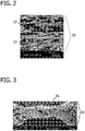
- a dual fiber cross-section 30 includes a layer of cylindrical shaped fibers 32 and a layer of trilobal shaped fibers 33. Fibers 32 and 33 are meltspun through jets into a plurality of continuous fibers which are uniformly deposited into a random three dimensional web. The web is then heated and embossed calendered which thermally bonds the web into a consolidated spunbond fabric 36, shown in FIG. 3 .
- Heat from contact of the calender roll embossing pattern softens or melts the thermoplastic fibers 30 which binds the nonwoven fibers together at the contact points of calender roll embossing pattern.
- the temperature is selected so that at least softening or fusing of the fibers 30 occurs. In one embodiment, the temperature is about 90°C to about 240°C.
- the desired connection of the fibers is caused by the melting and re-solidification of the fibers 32 and 33 after cooling.
- Round fibers 32 have diameter of about 18 microns to about 23 microns and trilobal fibers 33 have point to point cross-section distances of about 22-30 microns.
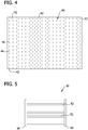
- a bond pattern 40 on base media 12 attains an acceptable durability to base media 12, while allowing more fiber to be available for filtration thus increasing filtration efficiency.
- Bond pattern 40 includes a plurality of parallel discontinuous lines 42 of bond area extending across base media 12.
- the parallel discontinuous lines 42 of bond area are off-set from each other so that at a location of no bond area 44 in a discontinuous line 42 is aligned with a bond area 46 of an adjacent discontinuous line 42.
- the basis weight of base media 12 is about 100 g/m 2 to about 330 g/m 2 , in another embodiment, about 100 g/m 2 to about 220 g/m 2 .
- Any suitable synthetic fiber can be used to make the nonwoven fabric of media substrate 12.
- Suitable materials for round 32 and trilobal 33 fibers include, but are not limited to, polyester, polyamide, polyolefin, thermoplastic polyurethane, polyetherimide, polyphenyl ether, polyphenylene sulfide, polysulfone, aramid, and mixtures thereof.
- nanofiber layer 20 is formed by an electro-blown spinning process that includes feeding a polymer solution into a spinning nozzle, applying a high voltage to the spinning nozzle, and discharging the polymer solution through the spinning nozzle while injecting compressed air into the lower end of the spinning nozzle.
- the applied high voltage ranges from about 1 kV to about 300 kV.
- the electro-blown spinning process of forming nanofibers and the unique apparatus used is described in detail in U.S. Patent Application Publication No. 2005/00677332 .
- the electro-blown spinning process provides a durable three dimensional filtration layer of nanofibers that is thicker than known nanofiber filtration layers on known filter media.
- the basis weight of nanofiber layer 20 is about 0.6 g/m 2 to about 20 g/m 2 , in another embodiment, about 2 g/m 2 to about 20 g/m 2 , in another embodiment, about 5 g/m 2 to about 10 g/m 2 , in another embodiment, about 1.5 g/m 2 to about 2.5 g/m 2 .
- the nanofibers in nanofiber layer 20 have an average diameter of about 500 nm or less.
- nanofiber layer 20 may be formed by electrospinning, centrifugal spinning, or melt blowing.
- Classical electrospinning is a technique described in detail in U.S. Patent No. 4,127,706 .
- a high voltage is applied to a polymer in solution to create nanofibers and nonwoven mats.
- total throughput in electrospinning processes is too low to be viable in forming heavier basis weight webs.
- Centrifugal spinning is a fiber forming process that includes supplying a spinning solution having at least one polymer dissolved in at least one solvent to a rotary sprayer having a rotating conical nozzle.
- the nozzle has a concave inner surface and a forward surface discharge edge.
- the spinning solution moves through the rotary sprayer along the concave inner surface so as to distribute the spinning solution toward the forward surface of the discharge edge of the nozzle. Separate fibrous streams are formed from the spinning solution while the solvent vaporizes to produce polymeric fibers in the presence or absence of an electrical field.
- a shaping fluid can flow around the nozzle to direct the spinning solution away from the rotary sprayer. The fibers are collected onto a collector to form a nanofiber web.
- melt blowing is described in detail in U.S. Patent No. 6,520,425 .
- Suitable polymers for forming nanofibers by the electro-blown spinning process are not restricted to thermoplastic polymers, and may include thermosetting polymers.
- Suitable polymers include, but are not limited to, polyimides, polyamides (nylon), polyaramides, polybenzimidazoles, polyetherimides, polyacrylonitriles, polyethylene terephthalate, polypropylene, polyanilines, polyethylene oxides, polyethylene naphthalates, polybutylene terephthalate, styrene butadiene rubber, polystyrene, polyvinyl chloride, polyvinyl alcohol, polyvinylidene chloride, polyvinyl butylene, polyacetal, polyamide, polyester, polyolefins, cellulose ether and ester, polyalkylene sulfide, polyarylene oxide, polysulfone, modified polysulfone polymers, and mixtures thereof.
- materials that fall within the generic classes of poly (vinylchloride), polymethylmethacrylate (and other acrylic resins), polystyrene, and copolymers thereof (including ABA type block copolymers), poly (vinylidene fluoride), poly (vinylidene chloride), polyvinylalcohol in various degrees of hydrolysis (87% to 99.5%) in crosslinked and non-crosslinked forms may be used and copolymer or derivative compounds thereof.
- One suitable class of polyamide condensation polymers are nylon materials, such as nylon-6, nylon-6, 6, nylon 6, 6-6, 10, and the like.
- the polymer solution is prepared by selecting a solvent that dissolves the selected polymers.
- the polymer solution can be mixed with additives, for example, plasticizers, ultraviolet ray stabilizers, crosslink agents, curing agents, reaction initiators, and the like. Although dissolving the polymers may not require any specific temperature ranges, heating may be needed for assisting the dissolution reaction.
- additives for example, plasticizers, ultraviolet ray stabilizers, crosslink agents, curing agents, reaction initiators, and the like.
- plasticizers can be added to the various polymers described above, in order to reduce the Tg of the fiber polymer.
- Suitable plasticizers will depend upon the polymer, as well as upon the particular end use of the nanofiber layer.
- nylon polymers can be plasticized with water or even residual solvent remaining from the electrospinning or electro-blown spinning process.
- plasticizers which can be useful in lowering polymer Tg include, but are not limited to, aliphatic glycols, aromatic sulphanomides, phthalate esters, including but not limited to, dibutyl phthalate, dihexl phthalate, dicyclohexyl phthalate, dioctyl phthalate, diisodecyl phthalate, diundecyl phthalate, didodecanyl phthalate, and diphenyl phthalate, and the like.
- FIG. 5 is a side illustration of a filter element 50 formed from filter media 10.
- filter media 10 includes a plurality of pleats 52.
- Filter element 50 includes a first end cap 54 and an opposing second end cap 56 with filter media 10 extending between end caps 54 and 56.
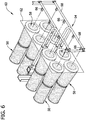
- Filter element 50 has a tubular shape with an interior conduit 58 (shown in FIG. 6 ).
- Filter element 50 is cylindrical in shape, but can also be conical as shown in FIG. 6 .
- Filter element 50 can also include an inner and/or an outer support liner to provide structural integrity of filter element 50 and/or support for filter media 10.
- FIG. 6 is a perspective illustration of a filter assembly 60 that includes a plurality of filter elements 50 mounted to a tube sheet 62 in pairs in an end to end relationship. Tube sheet 62 separates the dirty air side from the clean air side of filter assembly 60.
- a cleaning system 64 for cleaning filter elements 50 with pulsed air includes a plurality of air nozzles 66 mounted to air supply pipes 68. Pulses of compressed air directed into interior conduit 58 of filter elements 50 are used to clean filter elements 50 of collected dirt and dust.
- FIG. 7 shows a graphical representation of the comparison test and the enhanced filtration efficiency performance of spunbond base media 12.
- Bar A represents base substrate 12 at a basis weight of 165g/m 2
- Bar B represents a comparative base substrate at a basis weight of 230g/m 2
- Bar C represents a comparative base media substrate with a basis weight of 130g/m 2 .
- the base media substrates did not include a nanofiber layer.
- Base media substrate 12 has a higher efficiency than the comparative base at the 0.3 micron particle size tested at 5.3cm/s.
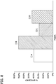
- FIG. 8 shows a graphical representation of the comparison test.
- Bar A represents base media substrate 12 at 165g/m 2
- Bar B represents base media substrate 12 at 165g/m 2 , including nanofiber layer 20.
- Bar C represents a comparative base media substrate and Bar D represents the comparative base media substrate including a nanofiber layer.
- Base media substrate 12 with and without nanofiber layer 20 had a higher efficiency than the comparative base substrate with and without a nanofiber layer.
- FIG. 9 shows a graphical representation of the comparison test.
- Bar A represents a comparative base media substrate and bar B represents the comparative base media substrate including a nanofiber layer.
- Bar C represents base media substrate 12 at 165g/m 2
- bar D represents base media substrate 12 at 165g/m 2 , including nanofiber layer 20.
- Base media substrate 12 with and without nanofiber layer 20 had a lower pressure drop than the comparative base substrate with and without a nanofiber layer.
- filter elements 50 formed from filter media 10 can be used for filtering an air stream in almost any application, for example, for filtering gas turbine inlet air.
- the unique construction of filter media 10 is more durable than known filter media and provides for relatively lower pressure drop build-up because of less deflection from the forces exerted on the filter media during the filtering and reverse cleaning operations.
- Filter elements 50 can produce an average efficiency greater than about 70% capture of the most penetrating particle size of aerosol or dust (about 0.3 to about 0.4 micron) as compared to an efficiency of about 50-55% of known filter elements.
- nanofiber layer 20 has a higher basis weight than known filter media which permits filter media 10 to clean down more effectively under reverse pulse cleaning than known filter media. Further, the high basis weight of nanofiber layer 20 provides for a durable three dimensional surface filtration layer which has an extensive tortuous path that permits high efficiency and fine particle capture without restricting air flow or increasing pressure drop.
- the example filter media of Examples 1 and 2 and Comparative Examples 3-7 illustrate a comparison of embodiments of filter media 10 with known filter media. Efficiency, resistance and quality factor were measured for each filter media of Examples 1 and 2 and Comparative Examples 3-7. Efficiency was measured in accordance with EN-1822 (1998) test procedure, resistance was measured in accordance with EN-1822 (1998), and quality factor Q f was calculated as described above.
- Example 1 is a spunbond polyester dual layer base media substrate containing round and trilobal fibers
- Example 2 is the base media substrate of Example 1 plus a 2 g/m 2 nanofiber layer formed by an electro-blown spinning process.
- Comparative Example 3 is a known drylaid polyester base media substrate
- Comparative Example 4 is the known dry-laid polyester base media substrate of Comparative Example 3 plus a 2 g/m 2 nanofiber layer.
- Comparative Example 5 is a wet-laid synthetic paper plus a ⁇ 0.5 g/m 2 nanofiber layer.
- Comparative Example 6 is a wet-laid synthetic paper
- Comparative Example 7 is the wet-laid synthetic paper of Example 6 plus a 20 g/m 2 meltblown fiber layer.
- Table I The example results are shown in Table I below.
Landscapes
- Chemical & Material Sciences (AREA)
- Chemical Kinetics & Catalysis (AREA)
- Filtering Materials (AREA)
- Nonwoven Fabrics (AREA)
- Filtering Of Dispersed Particles In Gases (AREA)
- Laminated Bodies (AREA)
Applications Claiming Priority (2)
| Application Number | Priority Date | Filing Date | Title |
|---|---|---|---|
| US12/184,782 US8512432B2 (en) | 2008-08-01 | 2008-08-01 | Composite filter media |
| PCT/US2009/052567 WO2010014980A2 (en) | 2008-08-01 | 2009-08-03 | Composite filter media |
Publications (2)
| Publication Number | Publication Date |
|---|---|
| EP2303426A2 EP2303426A2 (en) | 2011-04-06 |
| EP2303426B1 true EP2303426B1 (en) | 2018-09-19 |
Family
ID=41571605
Family Applications (1)
| Application Number | Title | Priority Date | Filing Date |
|---|---|---|---|
| EP09791095.4A Active EP2303426B1 (en) | 2008-08-01 | 2009-08-03 | Composite filter media |
Country Status (7)
| Country | Link |
|---|---|
| US (1) | US8512432B2 (enExample) |
| EP (1) | EP2303426B1 (enExample) |
| JP (1) | JP5400884B2 (enExample) |
| KR (1) | KR20110055588A (enExample) |
| CN (1) | CN102112196A (enExample) |
| BR (1) | BRPI0911816A2 (enExample) |
| WO (1) | WO2010014980A2 (enExample) |
Families Citing this family (45)
| Publication number | Priority date | Publication date | Assignee | Title |
|---|---|---|---|---|
| US10286407B2 (en) | 2007-11-29 | 2019-05-14 | General Electric Company | Inertial separator |
| US7922959B2 (en) * | 2008-08-01 | 2011-04-12 | E. I. Du Pont De Nemours And Company | Method of manufacturing a composite filter media |
| EP2408482A1 (en) | 2009-03-19 | 2012-01-25 | Millipore Corporation | Removal of microorganisms from fluid samples using nanofiber filtration media |
| DE102009016148A1 (de) * | 2009-04-03 | 2010-10-14 | Mcairlaid's Vliesstoffe Gmbh & Co. Kg | Filtermaterial zum Reinigen von Luft und Gasen |
| US8950587B2 (en) | 2009-04-03 | 2015-02-10 | Hollingsworth & Vose Company | Filter media suitable for hydraulic applications |
| JP2011194389A (ja) * | 2010-03-17 | 2011-10-06 | Nippon Air Filter Kk | 中高性能フィルタ |
| US10036107B2 (en) | 2010-08-23 | 2018-07-31 | Fiberweb Holdings Limited | Nonwoven web and fibers with electret properties, manufacturing processes thereof and their use |
| FR2964574B1 (fr) * | 2010-09-13 | 2015-01-02 | Ge Energy Products France Snc | Procede et systeme de controle d'un filtre |
| US8540805B2 (en) * | 2010-11-10 | 2013-09-24 | General Electric Company | Filter assembly for use in a turbine system |
| CN105413480B (zh) | 2011-04-01 | 2019-03-29 | Emd密理博公司 | 含有纳米纤维的复合材料结构 |
| US8715384B2 (en) * | 2011-06-23 | 2014-05-06 | General Electric Company | Inlet air pulse filtration system |
| CN102560896A (zh) * | 2012-02-13 | 2012-07-11 | 东华大学 | 一种具有纳米纤维层复合功能膜的制备方法及其装置 |
| CN102634930B (zh) * | 2012-04-13 | 2015-09-02 | 武汉纺织大学 | 一种含聚合物纳米纤维的滤材及其制备方法 |
| US10160833B2 (en) | 2012-04-26 | 2018-12-25 | The Regents Of The University Of Michigan | Synthesis and use of aramid nanofibers |
| EP2959509B1 (en) | 2013-02-14 | 2018-05-23 | Nanopareil, Llc | Electrospun hybrid nanofibre felt, method for making the same, and method for purifying biomolecules |
| JP2016530406A (ja) * | 2013-07-17 | 2016-09-29 | サビック グローバル テクノロジーズ ベスローテン フェンノートシャップ | 張力サブミクロン繊維とその用途 |
| WO2015016449A1 (ko) * | 2013-08-01 | 2015-02-05 | (주)에프티이앤이 | 내열성이 향상된 다층 나노섬유 필터 및 이의 제조방법 |
| CN104801113A (zh) * | 2014-01-28 | 2015-07-29 | 中国科学院宁波材料技术与工程研究所 | 一种高效空气过滤净化材料 |
| CN104014196B (zh) * | 2014-05-08 | 2016-04-20 | 武汉纺织大学 | 一种高吸附纳米纤维复合过滤材料及其制备方法 |
| WO2016025056A2 (en) | 2014-05-29 | 2016-02-18 | General Electric Company | Turbine engine and particle separators therefore |
| WO2016032585A2 (en) | 2014-05-29 | 2016-03-03 | General Electric Company | Turbine engine, components, and methods of cooling same |
| US9915176B2 (en) | 2014-05-29 | 2018-03-13 | General Electric Company | Shroud assembly for turbine engine |
| US11033845B2 (en) | 2014-05-29 | 2021-06-15 | General Electric Company | Turbine engine and particle separators therefore |
| KR20190011838A (ko) * | 2014-06-26 | 2019-02-07 | 이엠디 밀리포어 코포레이션 | 개선된 먼지 포집 능력을 갖는 필터 구조 |
| CN105582745A (zh) * | 2014-10-24 | 2016-05-18 | 张家港骏马无纺布有限公司 | 一种超细纤维过滤材料及其制备方法 |
| US10167725B2 (en) | 2014-10-31 | 2019-01-01 | General Electric Company | Engine component for a turbine engine |
| US10036319B2 (en) | 2014-10-31 | 2018-07-31 | General Electric Company | Separator assembly for a gas turbine engine |
| MX2017007417A (es) * | 2014-12-12 | 2018-04-20 | Univ Leland Stanford Junior | Filtro de aire para captura de pm2.5 de alta eficiencia. |
| KR102206959B1 (ko) | 2015-04-17 | 2021-01-25 | 이엠디 밀리포어 코포레이션 | 접선방향 유동 여과 모드에서 작동되는 나노섬유 한외여과막을 사용하여 샘플에서 목적하는 생물학적 물질을 정제하는 방법 |
| CN104801110B (zh) * | 2015-04-17 | 2016-03-23 | 盐城工学院 | 一种长毛绒与纳米静电纺毡复合滤料及其制备方法 |
| CN104971549A (zh) * | 2015-06-24 | 2015-10-14 | 上海市凌桥环保设备厂有限公司 | 工业细微颗粒过滤用防静电过滤材料及其制备方法 |
| FI20165589A (fi) * | 2015-08-22 | 2017-02-23 | Ahlstroem Oy | Partikkelien poistosuodatinmateriaali, jolla on parannettu teho partikkelien poistamiseksi polttoaineesta |
| US10428664B2 (en) | 2015-10-15 | 2019-10-01 | General Electric Company | Nozzle for a gas turbine engine |
| US9988936B2 (en) | 2015-10-15 | 2018-06-05 | General Electric Company | Shroud assembly for a gas turbine engine |
| US11014030B2 (en) | 2016-02-17 | 2021-05-25 | Hollingsworth & Vose Company | Filter media including flame retardant fibers |
| US10252200B2 (en) | 2016-02-17 | 2019-04-09 | Hollingsworth & Vose Company | Filter media including a filtration layer comprising synthetic fibers |
| US10704425B2 (en) | 2016-07-14 | 2020-07-07 | General Electric Company | Assembly for a gas turbine engine |
| EP3655142B1 (en) | 2017-07-21 | 2026-02-25 | Merck Millipore Ltd | Non-woven fiber membranes |
| JP6619042B2 (ja) * | 2018-03-28 | 2019-12-11 | 新和産業株式会社 | 複合構造体及びその製造装置 |
| JP6649420B2 (ja) * | 2018-03-28 | 2020-02-19 | 新和産業株式会社 | 複合構造体製造装置 |
| CN108722032B (zh) * | 2018-04-22 | 2021-04-09 | 广东曼森净化科技有限公司 | 用于建筑物新风系统的过滤材料 |
| EP3962626A1 (en) | 2019-05-01 | 2022-03-09 | Ascend Performance Materials Operations LLC | Filter media comprising polyamide nanofiber layer |
| CN110523159A (zh) * | 2019-08-22 | 2019-12-03 | 浙江尚朴科技有限公司 | 一种空气柱塞式自清洁除尘的过滤系统及其过滤方法 |
| US20210229004A1 (en) * | 2020-01-23 | 2021-07-29 | Jonell filtration Products, Inc. | Tubular filter with nonwoven media and method |
| JP2022185228A (ja) * | 2021-06-02 | 2022-12-14 | スリーエム イノベイティブ プロパティズ カンパニー | フィルタ |
Citations (2)
| Publication number | Priority date | Publication date | Assignee | Title |
|---|---|---|---|---|
| US4650506A (en) * | 1986-02-25 | 1987-03-17 | Donaldson Company, Inc. | Multi-layered microfiltration medium |
| EP1775006A1 (en) * | 2005-10-14 | 2007-04-18 | General Electric Company | Filter, filter media, and methods for making same |
Family Cites Families (34)
| Publication number | Priority date | Publication date | Assignee | Title |
|---|---|---|---|---|
| US5082476A (en) | 1990-10-19 | 1992-01-21 | Donaldson Company, Inc. | Filtration arrangement and method |
| US5437910A (en) | 1993-07-21 | 1995-08-01 | Steinbeis Gessner Gmbh | Multi-ply filter lasminate/composite for manufacturing vacuum cleaner filter bags |
| US6485811B1 (en) | 1994-09-28 | 2002-11-26 | Toray Industries, Inc. | Nonwoven fabric for pleated filters, and a production process therefor |
| US6165572A (en) | 1995-11-17 | 2000-12-26 | Donaldson Company, Inc. | Filter material construction and method |
| US5667562A (en) * | 1996-04-19 | 1997-09-16 | Kimberly-Clark Worldwide, Inc. | Spunbond vacuum cleaner webs |
| DE19630523C1 (de) | 1996-07-29 | 1998-03-12 | Freudenberg Carl Fa | Spinnvliesstoff und Vorrichtung zu dessen Herstellung |
| US6315806B1 (en) | 1997-09-23 | 2001-11-13 | Leonard Torobin | Method and apparatus for producing high efficiency fibrous media incorporating discontinuous sub-micron diameter fibers, and web media formed thereby |
| US6123751A (en) | 1998-06-09 | 2000-09-26 | Donaldson Company, Inc. | Filter construction resistant to the passage of water soluble materials; and method |
| US6110249A (en) * | 1999-03-26 | 2000-08-29 | Bha Technologies, Inc. | Filter element with membrane and bicomponent substrate |
| DE19919809C2 (de) | 1999-04-30 | 2003-02-06 | Fibermark Gessner Gmbh & Co | Staubfilterbeutel, enthaltend Nanofaservlies |
| DE60041154D1 (de) * | 1999-10-29 | 2009-01-29 | Hollingsworth & Vose Co | Filtermaterial |
| DE10016182B4 (de) | 2000-03-31 | 2004-07-29 | Carl Freudenberg Kg | Verfahren zur Herstellung eines plissierfähigen Filtermaterials aus einem Vliesstoff |
| US6395048B1 (en) * | 2000-08-30 | 2002-05-28 | International Truck Intellectual Property Company, L.L.C. | Air cleaner inlet device |
| US6743273B2 (en) | 2000-09-05 | 2004-06-01 | Donaldson Company, Inc. | Polymer, polymer microfiber, polymer nanofiber and applications including filter structures |
| US6800117B2 (en) | 2000-09-05 | 2004-10-05 | Donaldson Company, Inc. | Filtration arrangement utilizing pleated construction and method |
| US6673136B2 (en) | 2000-09-05 | 2004-01-06 | Donaldson Company, Inc. | Air filtration arrangements having fluted media constructions and methods |
| US20020092423A1 (en) | 2000-09-05 | 2002-07-18 | Gillingham Gary R. | Methods for filtering air for a gas turbine system |
| US6716274B2 (en) | 2000-09-05 | 2004-04-06 | Donaldson Company, Inc. | Air filter assembly for filtering an air stream to remove particulate matter entrained in the stream |
| US6740142B2 (en) | 2000-09-05 | 2004-05-25 | Donaldson Company, Inc. | Industrial bag house elements |
| US6746517B2 (en) | 2000-09-05 | 2004-06-08 | Donaldson Company, Inc. | Filter structure with two or more layers of fine fiber having extended useful service life |
| DE10051186B4 (de) | 2000-10-16 | 2005-04-07 | Fibermark Gessner Gmbh & Co. Ohg | Staubfilterbeutel mit hochporöser Trägermateriallage |
| US6872311B2 (en) * | 2002-01-31 | 2005-03-29 | Koslow Technologies Corporation | Nanofiber filter media |
| KR100549140B1 (ko) | 2002-03-26 | 2006-02-03 | 이 아이 듀폰 디 네모아 앤드 캄파니 | 일렉트로-브로운 방사법에 의한 초극세 나노섬유 웹제조방법 |
| DE50211962D1 (de) * | 2002-05-28 | 2008-05-08 | Hollingsworth & Vose Gmbh | Filtermedium |
| US20040038014A1 (en) | 2002-08-20 | 2004-02-26 | Donaldson Company, Inc. | Fiber containing filter media |
| WO2004069378A2 (de) | 2003-02-05 | 2004-08-19 | Helsa-Werke Helmut Sandler Gmbh & Co. Kg | Filterelement und verfahren zu seiner herstellung |
| US7008465B2 (en) | 2003-06-19 | 2006-03-07 | Donaldson Company, Inc. | Cleanable high efficiency filter media structure and applications for use |
| US7051883B2 (en) * | 2003-07-07 | 2006-05-30 | Reemay, Inc. | Wetlaid-spunbond laminate membrane support |
| US7235122B2 (en) * | 2004-11-08 | 2007-06-26 | E. I. Du Pont De Nemours And Company | Filtration media for filtering particulate material from gas streams |
| US20060137317A1 (en) * | 2004-12-28 | 2006-06-29 | Bryner Michael A | Filtration media for filtering particulate material from gas streams |
| US20070074628A1 (en) | 2005-09-30 | 2007-04-05 | Jones David C | Coalescing filtration medium and process |
| US20080017038A1 (en) * | 2006-07-21 | 2008-01-24 | 3M Innovative Properties Company | High efficiency hvac filter |
| US8361180B2 (en) * | 2006-11-27 | 2013-01-29 | E I Du Pont De Nemours And Company | Durable nanoweb scrim laminates |
| DE102007027299B4 (de) * | 2007-06-11 | 2009-02-26 | Johns Manville Europe Gmbh | Filter, Verfahren zu dessen Herstellung, dessen Verwendung sowie Filtermodule |
-
2008
- 2008-08-01 US US12/184,782 patent/US8512432B2/en active Active
-
2009
- 2009-08-03 EP EP09791095.4A patent/EP2303426B1/en active Active
- 2009-08-03 KR KR1020117004728A patent/KR20110055588A/ko not_active Ceased
- 2009-08-03 BR BRPI0911816A patent/BRPI0911816A2/pt not_active IP Right Cessation
- 2009-08-03 JP JP2011521375A patent/JP5400884B2/ja active Active
- 2009-08-03 WO PCT/US2009/052567 patent/WO2010014980A2/en not_active Ceased
- 2009-08-03 CN CN2009801296043A patent/CN102112196A/zh active Pending
Patent Citations (2)
| Publication number | Priority date | Publication date | Assignee | Title |
|---|---|---|---|---|
| US4650506A (en) * | 1986-02-25 | 1987-03-17 | Donaldson Company, Inc. | Multi-layered microfiltration medium |
| EP1775006A1 (en) * | 2005-10-14 | 2007-04-18 | General Electric Company | Filter, filter media, and methods for making same |
Also Published As
| Publication number | Publication date |
|---|---|
| BRPI0911816A2 (pt) | 2015-10-06 |
| JP5400884B2 (ja) | 2014-01-29 |
| CN102112196A (zh) | 2011-06-29 |
| US8512432B2 (en) | 2013-08-20 |
| JP2011529778A (ja) | 2011-12-15 |
| WO2010014980A2 (en) | 2010-02-04 |
| KR20110055588A (ko) | 2011-05-25 |
| EP2303426A2 (en) | 2011-04-06 |
| WO2010014980A3 (en) | 2010-06-10 |
| US20100024370A1 (en) | 2010-02-04 |
Similar Documents
| Publication | Publication Date | Title |
|---|---|---|
| EP2303426B1 (en) | Composite filter media | |
| EP2321028B1 (en) | Method of manufacturing a composite filter media | |
| US8308834B2 (en) | Composite filter media | |
| US7927540B2 (en) | Method of manufacturing a composite filter media | |
| EP2161066B1 (en) | Method of manufacturing composite filter media | |
| EP2161065B1 (en) | Filter Element Including a Composite Filter Media | |
| US8206481B2 (en) | HEPA (H-10) performance synthetic nonwoven and nanofiber composite filter media | |
| EP2198945A2 (en) | Gas Turbine Inlet Air Filtration Filter Element | |
| EP1970111B1 (en) | Composite filter media | |
| CN113646474A (zh) | 复合结构体、其制造方法及包含所述复合结构体的滤材 |
Legal Events
| Date | Code | Title | Description |
|---|---|---|---|
| PUAI | Public reference made under article 153(3) epc to a published international application that has entered the european phase |
Free format text: ORIGINAL CODE: 0009012 |
|
| 17P | Request for examination filed |
Effective date: 20110125 |
|
| AK | Designated contracting states |
Kind code of ref document: A2 Designated state(s): AT BE BG CH CY CZ DE DK EE ES FI FR GB GR HR HU IE IS IT LI LT LU LV MC MK MT NL NO PL PT RO SE SI SK SM TR |
|
| AX | Request for extension of the european patent |
Extension state: AL BA RS |
|
| DAX | Request for extension of the european patent (deleted) | ||
| 17Q | First examination report despatched |
Effective date: 20131017 |
|
| GRAP | Despatch of communication of intention to grant a patent |
Free format text: ORIGINAL CODE: EPIDOSNIGR1 |
|
| STAA | Information on the status of an ep patent application or granted ep patent |
Free format text: STATUS: GRANT OF PATENT IS INTENDED |
|
| INTG | Intention to grant announced |
Effective date: 20171103 |
|
| GRAJ | Information related to disapproval of communication of intention to grant by the applicant or resumption of examination proceedings by the epo deleted |
Free format text: ORIGINAL CODE: EPIDOSDIGR1 |
|
| STAA | Information on the status of an ep patent application or granted ep patent |
Free format text: STATUS: EXAMINATION IS IN PROGRESS |
|
| GRAP | Despatch of communication of intention to grant a patent |
Free format text: ORIGINAL CODE: EPIDOSNIGR1 |
|
| STAA | Information on the status of an ep patent application or granted ep patent |
Free format text: STATUS: GRANT OF PATENT IS INTENDED |
|
| INTC | Intention to grant announced (deleted) | ||
| INTG | Intention to grant announced |
Effective date: 20180328 |
|
| GRAS | Grant fee paid |
Free format text: ORIGINAL CODE: EPIDOSNIGR3 |
|
| GRAA | (expected) grant |
Free format text: ORIGINAL CODE: 0009210 |
|
| STAA | Information on the status of an ep patent application or granted ep patent |
Free format text: STATUS: THE PATENT HAS BEEN GRANTED |
|
| AK | Designated contracting states |
Kind code of ref document: B1 Designated state(s): AT BE BG CH CY CZ DE DK EE ES FI FR GB GR HR HU IE IS IT LI LT LU LV MC MK MT NL NO PL PT RO SE SI SK SM TR |
|
| REG | Reference to a national code |
Ref country code: GB Ref legal event code: FG4D |
|
| REG | Reference to a national code |
Ref country code: CH Ref legal event code: EP |
|
| REG | Reference to a national code |
Ref country code: DE Ref legal event code: R096 Ref document number: 602009054643 Country of ref document: DE |
|
| REG | Reference to a national code |
Ref country code: AT Ref legal event code: REF Ref document number: 1042576 Country of ref document: AT Kind code of ref document: T Effective date: 20181015 |
|
| REG | Reference to a national code |
Ref country code: IE Ref legal event code: FG4D |
|
| REG | Reference to a national code |
Ref country code: NL Ref legal event code: MP Effective date: 20180919 |
|
| PG25 | Lapsed in a contracting state [announced via postgrant information from national office to epo] |
Ref country code: BG Free format text: LAPSE BECAUSE OF FAILURE TO SUBMIT A TRANSLATION OF THE DESCRIPTION OR TO PAY THE FEE WITHIN THE PRESCRIBED TIME-LIMIT Effective date: 20181219 Ref country code: NO Free format text: LAPSE BECAUSE OF FAILURE TO SUBMIT A TRANSLATION OF THE DESCRIPTION OR TO PAY THE FEE WITHIN THE PRESCRIBED TIME-LIMIT Effective date: 20181219 Ref country code: FI Free format text: LAPSE BECAUSE OF FAILURE TO SUBMIT A TRANSLATION OF THE DESCRIPTION OR TO PAY THE FEE WITHIN THE PRESCRIBED TIME-LIMIT Effective date: 20180919 Ref country code: LT Free format text: LAPSE BECAUSE OF FAILURE TO SUBMIT A TRANSLATION OF THE DESCRIPTION OR TO PAY THE FEE WITHIN THE PRESCRIBED TIME-LIMIT Effective date: 20180919 Ref country code: GR Free format text: LAPSE BECAUSE OF FAILURE TO SUBMIT A TRANSLATION OF THE DESCRIPTION OR TO PAY THE FEE WITHIN THE PRESCRIBED TIME-LIMIT Effective date: 20181220 Ref country code: SE Free format text: LAPSE BECAUSE OF FAILURE TO SUBMIT A TRANSLATION OF THE DESCRIPTION OR TO PAY THE FEE WITHIN THE PRESCRIBED TIME-LIMIT Effective date: 20180919 |
|
| REG | Reference to a national code |
Ref country code: LT Ref legal event code: MG4D |
|
| PG25 | Lapsed in a contracting state [announced via postgrant information from national office to epo] |
Ref country code: LV Free format text: LAPSE BECAUSE OF FAILURE TO SUBMIT A TRANSLATION OF THE DESCRIPTION OR TO PAY THE FEE WITHIN THE PRESCRIBED TIME-LIMIT Effective date: 20180919 Ref country code: HR Free format text: LAPSE BECAUSE OF FAILURE TO SUBMIT A TRANSLATION OF THE DESCRIPTION OR TO PAY THE FEE WITHIN THE PRESCRIBED TIME-LIMIT Effective date: 20180919 |
|
| REG | Reference to a national code |
Ref country code: AT Ref legal event code: MK05 Ref document number: 1042576 Country of ref document: AT Kind code of ref document: T Effective date: 20180919 |
|
| PG25 | Lapsed in a contracting state [announced via postgrant information from national office to epo] |
Ref country code: PL Free format text: LAPSE BECAUSE OF FAILURE TO SUBMIT A TRANSLATION OF THE DESCRIPTION OR TO PAY THE FEE WITHIN THE PRESCRIBED TIME-LIMIT Effective date: 20180919 Ref country code: EE Free format text: LAPSE BECAUSE OF FAILURE TO SUBMIT A TRANSLATION OF THE DESCRIPTION OR TO PAY THE FEE WITHIN THE PRESCRIBED TIME-LIMIT Effective date: 20180919 Ref country code: IS Free format text: LAPSE BECAUSE OF FAILURE TO SUBMIT A TRANSLATION OF THE DESCRIPTION OR TO PAY THE FEE WITHIN THE PRESCRIBED TIME-LIMIT Effective date: 20190119 Ref country code: CZ Free format text: LAPSE BECAUSE OF FAILURE TO SUBMIT A TRANSLATION OF THE DESCRIPTION OR TO PAY THE FEE WITHIN THE PRESCRIBED TIME-LIMIT Effective date: 20180919 Ref country code: ES Free format text: LAPSE BECAUSE OF FAILURE TO SUBMIT A TRANSLATION OF THE DESCRIPTION OR TO PAY THE FEE WITHIN THE PRESCRIBED TIME-LIMIT Effective date: 20180919 Ref country code: IT Free format text: LAPSE BECAUSE OF FAILURE TO SUBMIT A TRANSLATION OF THE DESCRIPTION OR TO PAY THE FEE WITHIN THE PRESCRIBED TIME-LIMIT Effective date: 20180919 Ref country code: AT Free format text: LAPSE BECAUSE OF FAILURE TO SUBMIT A TRANSLATION OF THE DESCRIPTION OR TO PAY THE FEE WITHIN THE PRESCRIBED TIME-LIMIT Effective date: 20180919 Ref country code: NL Free format text: LAPSE BECAUSE OF FAILURE TO SUBMIT A TRANSLATION OF THE DESCRIPTION OR TO PAY THE FEE WITHIN THE PRESCRIBED TIME-LIMIT Effective date: 20180919 Ref country code: RO Free format text: LAPSE BECAUSE OF FAILURE TO SUBMIT A TRANSLATION OF THE DESCRIPTION OR TO PAY THE FEE WITHIN THE PRESCRIBED TIME-LIMIT Effective date: 20180919 |
|
| PG25 | Lapsed in a contracting state [announced via postgrant information from national office to epo] |
Ref country code: SK Free format text: LAPSE BECAUSE OF FAILURE TO SUBMIT A TRANSLATION OF THE DESCRIPTION OR TO PAY THE FEE WITHIN THE PRESCRIBED TIME-LIMIT Effective date: 20180919 Ref country code: SM Free format text: LAPSE BECAUSE OF FAILURE TO SUBMIT A TRANSLATION OF THE DESCRIPTION OR TO PAY THE FEE WITHIN THE PRESCRIBED TIME-LIMIT Effective date: 20180919 Ref country code: PT Free format text: LAPSE BECAUSE OF FAILURE TO SUBMIT A TRANSLATION OF THE DESCRIPTION OR TO PAY THE FEE WITHIN THE PRESCRIBED TIME-LIMIT Effective date: 20190119 |
|
| REG | Reference to a national code |
Ref country code: DE Ref legal event code: R097 Ref document number: 602009054643 Country of ref document: DE |
|
| PLBE | No opposition filed within time limit |
Free format text: ORIGINAL CODE: 0009261 |
|
| STAA | Information on the status of an ep patent application or granted ep patent |
Free format text: STATUS: NO OPPOSITION FILED WITHIN TIME LIMIT |
|
| PG25 | Lapsed in a contracting state [announced via postgrant information from national office to epo] |
Ref country code: DK Free format text: LAPSE BECAUSE OF FAILURE TO SUBMIT A TRANSLATION OF THE DESCRIPTION OR TO PAY THE FEE WITHIN THE PRESCRIBED TIME-LIMIT Effective date: 20180919 |
|
| 26N | No opposition filed |
Effective date: 20190620 |
|
| PG25 | Lapsed in a contracting state [announced via postgrant information from national office to epo] |
Ref country code: SI Free format text: LAPSE BECAUSE OF FAILURE TO SUBMIT A TRANSLATION OF THE DESCRIPTION OR TO PAY THE FEE WITHIN THE PRESCRIBED TIME-LIMIT Effective date: 20180919 |
|
| PG25 | Lapsed in a contracting state [announced via postgrant information from national office to epo] |
Ref country code: TR Free format text: LAPSE BECAUSE OF FAILURE TO SUBMIT A TRANSLATION OF THE DESCRIPTION OR TO PAY THE FEE WITHIN THE PRESCRIBED TIME-LIMIT Effective date: 20180919 |
|
| PG25 | Lapsed in a contracting state [announced via postgrant information from national office to epo] |
Ref country code: MC Free format text: LAPSE BECAUSE OF FAILURE TO SUBMIT A TRANSLATION OF THE DESCRIPTION OR TO PAY THE FEE WITHIN THE PRESCRIBED TIME-LIMIT Effective date: 20180919 Ref country code: LI Free format text: LAPSE BECAUSE OF NON-PAYMENT OF DUE FEES Effective date: 20190831 Ref country code: LU Free format text: LAPSE BECAUSE OF NON-PAYMENT OF DUE FEES Effective date: 20190803 Ref country code: CH Free format text: LAPSE BECAUSE OF NON-PAYMENT OF DUE FEES Effective date: 20190831 |
|
| REG | Reference to a national code |
Ref country code: BE Ref legal event code: MM Effective date: 20190831 |
|
| PG25 | Lapsed in a contracting state [announced via postgrant information from national office to epo] |
Ref country code: IE Free format text: LAPSE BECAUSE OF NON-PAYMENT OF DUE FEES Effective date: 20190803 |
|
| PG25 | Lapsed in a contracting state [announced via postgrant information from national office to epo] |
Ref country code: BE Free format text: LAPSE BECAUSE OF NON-PAYMENT OF DUE FEES Effective date: 20190831 |
|
| PG25 | Lapsed in a contracting state [announced via postgrant information from national office to epo] |
Ref country code: CY Free format text: LAPSE BECAUSE OF FAILURE TO SUBMIT A TRANSLATION OF THE DESCRIPTION OR TO PAY THE FEE WITHIN THE PRESCRIBED TIME-LIMIT Effective date: 20180919 |
|
| PG25 | Lapsed in a contracting state [announced via postgrant information from national office to epo] |
Ref country code: MT Free format text: LAPSE BECAUSE OF FAILURE TO SUBMIT A TRANSLATION OF THE DESCRIPTION OR TO PAY THE FEE WITHIN THE PRESCRIBED TIME-LIMIT Effective date: 20180919 Ref country code: HU Free format text: LAPSE BECAUSE OF FAILURE TO SUBMIT A TRANSLATION OF THE DESCRIPTION OR TO PAY THE FEE WITHIN THE PRESCRIBED TIME-LIMIT; INVALID AB INITIO Effective date: 20090803 |
|
| PG25 | Lapsed in a contracting state [announced via postgrant information from national office to epo] |
Ref country code: MK Free format text: LAPSE BECAUSE OF FAILURE TO SUBMIT A TRANSLATION OF THE DESCRIPTION OR TO PAY THE FEE WITHIN THE PRESCRIBED TIME-LIMIT Effective date: 20180919 |
|
| REG | Reference to a national code |
Ref country code: DE Ref legal event code: R081 Ref document number: 602009054643 Country of ref document: DE Owner name: DUPONT SAFETY & CONSTRUCTION, INC., WILMINGTON, US Free format text: FORMER OWNER: E.I. DU PONT DE NEMOURS AND COMPANY, WILMINGTON, DEL., US |
|
| REG | Reference to a national code |
Ref country code: GB Ref legal event code: 732E Free format text: REGISTERED BETWEEN 20221027 AND 20221102 |
|
| P01 | Opt-out of the competence of the unified patent court (upc) registered |
Effective date: 20230528 |
|
| PGFP | Annual fee paid to national office [announced via postgrant information from national office to epo] |
Ref country code: DE Payment date: 20250702 Year of fee payment: 17 |
|
| PGFP | Annual fee paid to national office [announced via postgrant information from national office to epo] |
Ref country code: GB Payment date: 20250703 Year of fee payment: 17 |
|
| PGFP | Annual fee paid to national office [announced via postgrant information from national office to epo] |
Ref country code: FR Payment date: 20250703 Year of fee payment: 17 |