EP2303198B1 - Membranimplantat zur behandlung von hirnarterienaneurysmen - Google Patents
Membranimplantat zur behandlung von hirnarterienaneurysmen Download PDFInfo
- Publication number
- EP2303198B1 EP2303198B1 EP09777206.5A EP09777206A EP2303198B1 EP 2303198 B1 EP2303198 B1 EP 2303198B1 EP 09777206 A EP09777206 A EP 09777206A EP 2303198 B1 EP2303198 B1 EP 2303198B1
- Authority
- EP
- European Patent Office
- Prior art keywords
- membrane
- implant
- implant according
- membrane implant
- vessel
- Prior art date
- Legal status (The legal status is an assumption and is not a legal conclusion. Google has not performed a legal analysis and makes no representation as to the accuracy of the status listed.)
- Active
Links
Images

Classifications
-
- A—HUMAN NECESSITIES
- A61—MEDICAL OR VETERINARY SCIENCE; HYGIENE
- A61F—FILTERS IMPLANTABLE INTO BLOOD VESSELS; PROSTHESES; DEVICES PROVIDING PATENCY TO, OR PREVENTING COLLAPSING OF, TUBULAR STRUCTURES OF THE BODY, e.g. STENTS; ORTHOPAEDIC, NURSING OR CONTRACEPTIVE DEVICES; FOMENTATION; TREATMENT OR PROTECTION OF EYES OR EARS; BANDAGES, DRESSINGS OR ABSORBENT PADS; FIRST-AID KITS
- A61F2/00—Filters implantable into blood vessels; Prostheses, i.e. artificial substitutes or replacements for parts of the body; Appliances for connecting them with the body; Devices providing patency to, or preventing collapsing of, tubular structures of the body, e.g. stents
- A61F2/82—Devices providing patency to, or preventing collapsing of, tubular structures of the body, e.g. stents
- A61F2/856—Single tubular stent with a side portal passage
-
- A—HUMAN NECESSITIES
- A61—MEDICAL OR VETERINARY SCIENCE; HYGIENE
- A61B—DIAGNOSIS; SURGERY; IDENTIFICATION
- A61B17/00—Surgical instruments, devices or methods
- A61B17/12—Surgical instruments, devices or methods for ligaturing or otherwise compressing tubular parts of the body, e.g. blood vessels or umbilical cord
- A61B17/12022—Occluding by internal devices, e.g. balloons or releasable wires
-
- A—HUMAN NECESSITIES
- A61—MEDICAL OR VETERINARY SCIENCE; HYGIENE
- A61B—DIAGNOSIS; SURGERY; IDENTIFICATION
- A61B17/00—Surgical instruments, devices or methods
- A61B17/12—Surgical instruments, devices or methods for ligaturing or otherwise compressing tubular parts of the body, e.g. blood vessels or umbilical cord
- A61B17/12022—Occluding by internal devices, e.g. balloons or releasable wires
- A61B17/12099—Occluding by internal devices, e.g. balloons or releasable wires characterised by the location of the occluder
- A61B17/12109—Occluding by internal devices, e.g. balloons or releasable wires characterised by the location of the occluder in a blood vessel
- A61B17/12113—Occluding by internal devices, e.g. balloons or releasable wires characterised by the location of the occluder in a blood vessel within an aneurysm
- A61B17/12118—Occluding by internal devices, e.g. balloons or releasable wires characterised by the location of the occluder in a blood vessel within an aneurysm for positioning in conjunction with a stent
-
- A—HUMAN NECESSITIES
- A61—MEDICAL OR VETERINARY SCIENCE; HYGIENE
- A61F—FILTERS IMPLANTABLE INTO BLOOD VESSELS; PROSTHESES; DEVICES PROVIDING PATENCY TO, OR PREVENTING COLLAPSING OF, TUBULAR STRUCTURES OF THE BODY, e.g. STENTS; ORTHOPAEDIC, NURSING OR CONTRACEPTIVE DEVICES; FOMENTATION; TREATMENT OR PROTECTION OF EYES OR EARS; BANDAGES, DRESSINGS OR ABSORBENT PADS; FIRST-AID KITS
- A61F2/00—Filters implantable into blood vessels; Prostheses, i.e. artificial substitutes or replacements for parts of the body; Appliances for connecting them with the body; Devices providing patency to, or preventing collapsing of, tubular structures of the body, e.g. stents
- A61F2/02—Prostheses implantable into the body
- A61F2/04—Hollow or tubular parts of organs, e.g. bladders, tracheae, bronchi or bile ducts
- A61F2/06—Blood vessels
- A61F2/07—Stent-grafts
-
- A—HUMAN NECESSITIES
- A61—MEDICAL OR VETERINARY SCIENCE; HYGIENE
- A61F—FILTERS IMPLANTABLE INTO BLOOD VESSELS; PROSTHESES; DEVICES PROVIDING PATENCY TO, OR PREVENTING COLLAPSING OF, TUBULAR STRUCTURES OF THE BODY, e.g. STENTS; ORTHOPAEDIC, NURSING OR CONTRACEPTIVE DEVICES; FOMENTATION; TREATMENT OR PROTECTION OF EYES OR EARS; BANDAGES, DRESSINGS OR ABSORBENT PADS; FIRST-AID KITS
- A61F2/00—Filters implantable into blood vessels; Prostheses, i.e. artificial substitutes or replacements for parts of the body; Appliances for connecting them with the body; Devices providing patency to, or preventing collapsing of, tubular structures of the body, e.g. stents
- A61F2/82—Devices providing patency to, or preventing collapsing of, tubular structures of the body, e.g. stents
- A61F2/92—Stents in the form of a rolled-up sheet expanding after insertion into the vessel, e.g. with a spiral shape in cross-section
-
- A—HUMAN NECESSITIES
- A61—MEDICAL OR VETERINARY SCIENCE; HYGIENE
- A61F—FILTERS IMPLANTABLE INTO BLOOD VESSELS; PROSTHESES; DEVICES PROVIDING PATENCY TO, OR PREVENTING COLLAPSING OF, TUBULAR STRUCTURES OF THE BODY, e.g. STENTS; ORTHOPAEDIC, NURSING OR CONTRACEPTIVE DEVICES; FOMENTATION; TREATMENT OR PROTECTION OF EYES OR EARS; BANDAGES, DRESSINGS OR ABSORBENT PADS; FIRST-AID KITS
- A61F2/00—Filters implantable into blood vessels; Prostheses, i.e. artificial substitutes or replacements for parts of the body; Appliances for connecting them with the body; Devices providing patency to, or preventing collapsing of, tubular structures of the body, e.g. stents
- A61F2/95—Instruments specially adapted for placement or removal of stents or stent-grafts
- A61F2/954—Instruments specially adapted for placement or removal of stents or stent-grafts for placing stents or stent-grafts in a bifurcation
-
- A—HUMAN NECESSITIES
- A61—MEDICAL OR VETERINARY SCIENCE; HYGIENE
- A61B—DIAGNOSIS; SURGERY; IDENTIFICATION
- A61B17/00—Surgical instruments, devices or methods
- A61B17/12—Surgical instruments, devices or methods for ligaturing or otherwise compressing tubular parts of the body, e.g. blood vessels or umbilical cord
- A61B17/12022—Occluding by internal devices, e.g. balloons or releasable wires
- A61B2017/1205—Introduction devices
-
- A—HUMAN NECESSITIES
- A61—MEDICAL OR VETERINARY SCIENCE; HYGIENE
- A61F—FILTERS IMPLANTABLE INTO BLOOD VESSELS; PROSTHESES; DEVICES PROVIDING PATENCY TO, OR PREVENTING COLLAPSING OF, TUBULAR STRUCTURES OF THE BODY, e.g. STENTS; ORTHOPAEDIC, NURSING OR CONTRACEPTIVE DEVICES; FOMENTATION; TREATMENT OR PROTECTION OF EYES OR EARS; BANDAGES, DRESSINGS OR ABSORBENT PADS; FIRST-AID KITS
- A61F2/00—Filters implantable into blood vessels; Prostheses, i.e. artificial substitutes or replacements for parts of the body; Appliances for connecting them with the body; Devices providing patency to, or preventing collapsing of, tubular structures of the body, e.g. stents
- A61F2/82—Devices providing patency to, or preventing collapsing of, tubular structures of the body, e.g. stents
-
- A—HUMAN NECESSITIES
- A61—MEDICAL OR VETERINARY SCIENCE; HYGIENE
- A61F—FILTERS IMPLANTABLE INTO BLOOD VESSELS; PROSTHESES; DEVICES PROVIDING PATENCY TO, OR PREVENTING COLLAPSING OF, TUBULAR STRUCTURES OF THE BODY, e.g. STENTS; ORTHOPAEDIC, NURSING OR CONTRACEPTIVE DEVICES; FOMENTATION; TREATMENT OR PROTECTION OF EYES OR EARS; BANDAGES, DRESSINGS OR ABSORBENT PADS; FIRST-AID KITS
- A61F2/00—Filters implantable into blood vessels; Prostheses, i.e. artificial substitutes or replacements for parts of the body; Appliances for connecting them with the body; Devices providing patency to, or preventing collapsing of, tubular structures of the body, e.g. stents
- A61F2/02—Prostheses implantable into the body
- A61F2/30—Joints
- A61F2002/30001—Additional features of subject-matter classified in A61F2/28, A61F2/30 and subgroups thereof
- A61F2002/30003—Material related properties of the prosthesis or of a coating on the prosthesis
- A61F2002/3006—Properties of materials and coating materials
- A61F2002/3008—Properties of materials and coating materials radio-opaque, e.g. radio-opaque markers
-
- A—HUMAN NECESSITIES
- A61—MEDICAL OR VETERINARY SCIENCE; HYGIENE
- A61F—FILTERS IMPLANTABLE INTO BLOOD VESSELS; PROSTHESES; DEVICES PROVIDING PATENCY TO, OR PREVENTING COLLAPSING OF, TUBULAR STRUCTURES OF THE BODY, e.g. STENTS; ORTHOPAEDIC, NURSING OR CONTRACEPTIVE DEVICES; FOMENTATION; TREATMENT OR PROTECTION OF EYES OR EARS; BANDAGES, DRESSINGS OR ABSORBENT PADS; FIRST-AID KITS
- A61F2/00—Filters implantable into blood vessels; Prostheses, i.e. artificial substitutes or replacements for parts of the body; Appliances for connecting them with the body; Devices providing patency to, or preventing collapsing of, tubular structures of the body, e.g. stents
- A61F2/82—Devices providing patency to, or preventing collapsing of, tubular structures of the body, e.g. stents
- A61F2002/823—Stents, different from stent-grafts, adapted to cover an aneurysm
-
- A—HUMAN NECESSITIES
- A61—MEDICAL OR VETERINARY SCIENCE; HYGIENE
- A61F—FILTERS IMPLANTABLE INTO BLOOD VESSELS; PROSTHESES; DEVICES PROVIDING PATENCY TO, OR PREVENTING COLLAPSING OF, TUBULAR STRUCTURES OF THE BODY, e.g. STENTS; ORTHOPAEDIC, NURSING OR CONTRACEPTIVE DEVICES; FOMENTATION; TREATMENT OR PROTECTION OF EYES OR EARS; BANDAGES, DRESSINGS OR ABSORBENT PADS; FIRST-AID KITS
- A61F2250/00—Special features of prostheses classified in groups A61F2/00 - A61F2/26 or A61F2/82 or A61F9/00 or A61F11/00 or subgroups thereof
- A61F2250/0058—Additional features; Implant or prostheses properties not otherwise provided for
- A61F2250/006—Additional features; Implant or prostheses properties not otherwise provided for modular
-
- A—HUMAN NECESSITIES
- A61—MEDICAL OR VETERINARY SCIENCE; HYGIENE
- A61F—FILTERS IMPLANTABLE INTO BLOOD VESSELS; PROSTHESES; DEVICES PROVIDING PATENCY TO, OR PREVENTING COLLAPSING OF, TUBULAR STRUCTURES OF THE BODY, e.g. STENTS; ORTHOPAEDIC, NURSING OR CONTRACEPTIVE DEVICES; FOMENTATION; TREATMENT OR PROTECTION OF EYES OR EARS; BANDAGES, DRESSINGS OR ABSORBENT PADS; FIRST-AID KITS
- A61F2250/00—Special features of prostheses classified in groups A61F2/00 - A61F2/26 or A61F2/82 or A61F9/00 or A61F11/00 or subgroups thereof
- A61F2250/0058—Additional features; Implant or prostheses properties not otherwise provided for
- A61F2250/0096—Markers and sensors for detecting a position or changes of a position of an implant, e.g. RF sensors, ultrasound markers
- A61F2250/0098—Markers and sensors for detecting a position or changes of a position of an implant, e.g. RF sensors, ultrasound markers radio-opaque, e.g. radio-opaque markers
Definitions
- the invention relates to a membrane implant for the treatment of cerebral artery aneurysms, wherein the implant is endovascularly implantable into vascular segments at the skull and brain base of diseased (aneurysmal) extension and, in combination with a stent, bridges the diseased vessel segment from the inside and shuts it off from the bloodstream.
- WO 2006/111801 discloses a membrane implant having the features of the preamble of claim 1.
- the invention is based on the problem to provide an endovascular placeable implant, which in combination with already available uncoated stents is able to take over the function of a previously (and foreseeably) unavailable, suitable covered stent for the treatment of cerebral artery aneurysms.
- the diseased vessel portion is bridged with the aneurysm from the inside with a membrane and switched off from the blood stream.
- the membrane implant is presented in a microcatheter folded into the diseased portion of the vessel. After correct placement, the implant is deployed by retraction of the microcatheter and fixed and stabilized with the help of a stent, so that the functionality of a covered stent is given.
- the disadvantage of insufficient flexibility is circumvented by successive implantation of two flexible modules.
- the membrane implants according to the invention generally have a length of 5 mm and 30 mm and a radius of between 1 mm and 3 mm, the dimensions resulting from the dimension of the diseased segment of the vessel on the one hand and the type of vasodilation on the other.
- the films have a thickness in the range of 10 to 50 microns; They consist of a medically compatible plastic, for example polyurethane, polyalkylene, polyamide, polytetrafluoroethylene or PET.
- the plastic membrane of the implant according to the invention is cylindrical or cylindrical segment-shaped, with the shape resulting from the expanded state in the vessel after implantation.
- the implant is guided in a microcatheter in more or less collapsed form.
- the cylinder or the cylinder segment can be closed, but also open, ie slotted present.
- the latter embodiment has the advantage that the membrane can optimally adapt to the vessel diameter when placed in the vessel to be treated, wherein the side edges of the longitudinal slot can overlap slightly or leave a free space in the longitudinal direction.
- a self-erecting clip which fixes the cylindrical shape and supported against the vessel wall.
- stress may for example consist of a shape memory material, such as nitinol.
- the clasp may also be made of a radiopaque material, such as platinum or a platinum alloy, or of a shape memory material, such as nitinol, which is provided with a radiopaque sheath.
- a sheath can be present for example in the form of a wire helix made of a radiopaque material such as platinum or a platinum alloy.
- wire clips and plastic clips may be provided which have the required shape memory properties.
- the self-erecting clips made of wire or plastic can completely or partially surround the cylinder of the plastic membrane at one or both ends. As a rule, a partial enclosure is sufficient. In this case, an enclosure of the diaphragm cylinder at the proximal end, d. H. at the end facing the guidewire or blood stream, respectively.
- an X-ray visible, flexible longitudinal wire can be provided which runs along the cylinder wall over the entire cylinder length and is optionally connected at one or both ends to the self-erecting clasp.
- the preferred material for this purpose may serve a wire made of platinum or a platinum alloy.
- alloys of platinum and iridium have become known for radiopaque implants.
- the membrane implant according to the invention is releasably connected to a guide wire, so that it can be reliably placed by the attending physician.
- the connection can be made for example via a coupling point, are provided at the coupling element on the guide wire and on the proximal or distal clip. If the clasp is made of a metal, selective welds are possible can be dissolved under current effect in a manner known per se. The technique is the same as that developed for the placement of occlusion helices in aneurysms.
- the membrane implant has two membrane films which are superimposed.
- each of the membrane films for example, have a thickness of about 10 microns. Any clips, wires and other elements may be arranged between the two membrane sheets, with a fixation via welding or gluing comes into question.
- reinforcing threads introduced between the films may be provided, for example those made of Nitinol, which have shape memory properties.
- Such wires may be arranged at regular intervals, for example those of 1 to 10 mm, the distances depending on the required clamping force, the strength of the reinforcing threads and the size of the implant.
- these wires run obliquely, for example at an angle of 30 to 60 ° and in particular of about 55 ° to the longitudinal direction of the implant, wherein a crosswise arrangement of the wires may be provided, so that a network or lattic work arises.
- shape memory threads for example, radiopaque filaments can be incorporated, which allow a visual representation of the implant in the body.
- reinforcing threads with shape memory properties can also be made of a suitable plastic, for example.
- the implant according to the invention is coupled to an insertion wire and can be released from it.
- insertion wires are known per se. They have, for example, a diameter of 0.014 inches (0.356 mm) and allow the guidance of the implant through a conventional microcatheter. It is expedient that such a guide wire is guided through the lumen of the cylindrical implant and is expediently radiopaque visible at its distal end.
- the guidewire may be at its distal end or in the Near the distal end have a plastic cone, which is helpful in the guidance in the micro catheter and the placement on the diseased segment of the vessel.
- the membrane implant may in particular consist of a complete cylinder, but is often also formed from a cylinder segment, which is laterally, opposite a Seitwandaneurysma, open, so that outgoing vessels are not closed.
- the implant has the shape of an obliquely cut cylinder.
- the invention relates to a kit of a membrane implant according to the invention together with a dimensionally matched stent as well as the guide wires and possibly catheters required for guiding the stent and the implant.
- this is a balloon-stented stent that is implanted by hydraulic expansion.
- a stent of a shape memory material such as nitinol, can be used, which expands after application of a micro catheter in place itself and braced against vessel wall to fix the membrane.
- stents are known per se.
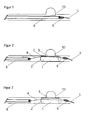
- FIGS. 1 to 3 show an embodiment of the invention for the treatment of so-called sidewall aneurysms.
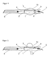
- Figure 4 shows a released, unfolded implant after detachment of the guidewire, as can be used to treat spindle-shaped (fusiform) aneurysms.
- FIG. 5 An embodiment of the invention for the treatment of Seitwandaneurysmen against which a vessel springs, whose departure may not be closed, is in Figure 5 shown.
- the implant consists of an obliquely cut membrane which has the full circumference proximally (facing the microcatheter or treating physician) and is shortened distally (the side facing away from the attending physician) to a partial extent.
- the springing vessel remains free on the open side of the membrane implant 1.
- the membrane implant for distal stabilization is additionally provided with a radiopaque, self-righting distal wire clip 9.
- the membrane may deploy, assisted by the self-righting wire clip (s) and blood flow in the diseased segment of the vessel ( Fig. 2 ).
- the self-righting wire clip (s) By observing in particular the X-ray-visible longitudinal wire, an optimized placement with respect to the longitudinal position and rotation of the membrane can be achieved.
- the implant After subsequent detachment of the insertion wire ( Fig. 3 ), the implant now unstably fixed only by the pressure of the blood and the wire clip (s) is definitively fixed in its position by a stent (already brought before the detachment over the insertion wire) which must project beyond the membrane implant proximally and distally.
- FIGS 1 to 3 show a first embodiment of a membrane implant according to the invention in a blood vessel with a Seitwandaneurysma 10.
- the implant 1 has substantially cylindrical shapes and may consist of a tubular plastic cylinder, but is usually formed from a deformed into a cylinder plastic membrane sheet.
- a metal clip 2 which is preferably made of nitinol and for the sake of better visibility may be sheathed with a radiopaque material.
- a flexible radiopaque longitudinal wire 3 which allows the attending physician, the exact placement of the implant with respect to the Seitwandaneurysma 10.
- the implant is delivered to and from the treatment site via a microcatheter 8, which typically has a radiopaque tip released by means of an insertion wire 4.
- the insertion wire 4 is connected via a welding / detachment point 7 with the clip 2 and can be removed electrolytically by brief action of direct current (see Figure 3 ).
- the guidewire itself has a radiopaque tip 5 together with a plastic ball or cone 6 for navigation and imaging.
- the plastic membrane preferably has the self-righting clip 2 at the proximal end to abut the membrane against the vessel wall.
- a second clip may be located distally, as in FIG Figure 4 shown.
- a second clip 9 also at the distal end of the membrane implant 1, see Figure 4 ,
- Figure 5 shows the special case of a vascular malformation compared to a vascular branch.
- the membrane implant must leave the branch, so it is cut obliquely.
- self-righting clips 2 and 9 are located at the proximal and distal ends of the membrane implant.
- FIG. 6 shows a particular embodiment of a membrane implant, which has to generate a higher voltage embedded Nitinolfäden 11.
- the implant consists of a double membrane with embedded nitinol threads which run at a regular distance of, for example, 3 mm at an angle of 45 ° to the longitudinal direction of the implant ( Figure 6a ).
- the reinforcing threads can also form a latticework in which the reinforcing threads 11 extend at right angles to each other, also at an angle of 45 ° to the longitudinal direction of the implant ( Figure 6b ).
- the implant is preloaded in a manner known per se, advanced into a microcatheter in a rolled condition, and released in the same manner as shown, for example, in Figs.
- the Guidewire can be welded to one of the reinforcing wires 11 and as known electrolytically detached.
- the implant Upon release from the microcatheter, the implant springs open in the manner of a coil spring and abuts the vessel wall, completing the malformation, such as a sidewall aneurysm.
- the nitinol threads may be welded or glued in between the two cover sheets in the implant. It is possible to retract individual marker threads from a radiopaque material to render the membrane implant radiopaque in this manner.
- the membrane implant according to the invention is additionally fixed and secured at the implantation site by a subsequently inserted neurostent.
- a fuse can, however, in the embodiment of the Figure 6 be dispensable, since here the reinforcing threads with an imprinted cylindrical shape (shape memory material) takes over the fuse in the vessel.
Landscapes
- Health & Medical Sciences (AREA)
- Engineering & Computer Science (AREA)
- Biomedical Technology (AREA)
- Life Sciences & Earth Sciences (AREA)
- Veterinary Medicine (AREA)
- Heart & Thoracic Surgery (AREA)
- Vascular Medicine (AREA)
- Animal Behavior & Ethology (AREA)
- General Health & Medical Sciences (AREA)
- Public Health (AREA)
- Oral & Maxillofacial Surgery (AREA)
- Cardiology (AREA)
- Transplantation (AREA)
- Surgery (AREA)
- Medical Informatics (AREA)
- Nuclear Medicine, Radiotherapy & Molecular Imaging (AREA)
- Reproductive Health (AREA)
- Molecular Biology (AREA)
- Neurosurgery (AREA)
- Gastroenterology & Hepatology (AREA)
- Pulmonology (AREA)
- Surgical Instruments (AREA)
- Prostheses (AREA)
- Media Introduction/Drainage Providing Device (AREA)
Description
- Die Erfindung betrifft ein Membranimplantat zur Behandlung von Hirnarterienaneurysmen, wobei das Implantat in Gefäßsegmente an der Schädel- und Hirnbasis krankhafter (aneurysmatischer) Erweiterung endovaskulär implantierbar ist und in Kombination mit einem Stent das erkrankte Gefäßsegment von innen überbrückt und aus dem Blutstrom ausschaltet.
- Die radiologisch-interventionelle Behandlung umschriebener krankhafter Erweiterungen von Schlagadern (Aneurysmen), durch endovaskuläre (d.h. durch die Blutbahn hindurch) Implantation blutundurchlässig beschichteter (gecoverter) Metallgitterprothesen (Stents), ist ausserhalb des Schädels gängige und erfolgreiche Praxis. Hierdurch wird der erkrankte Gefäßabschnitt überbrückt und ein weiteres Wachsen und letztlich eine Ruptur des Aneurysmas verhindert.
- An den Gefäßen der Schädel- und Hirnbasis scheitert dieses Konzept bisher regelmäßig daran, dass verfügbare gecoverte Stents oder deren Einführbestecke nicht flexibel genug sind, um bis in die erkrankten Gefäßabschnitte vorgeführt werden zu können. Es gibt bisher lediglich unbeschichtete Stents, die über eine ausreichende Flexibilität auch des Einführbesteckes verfügen. Diese können auf Grund ihrer Blutdurchlässigkeit, Aneurysmen jedoch nicht aus der Zirkulation ausschalten.
-
WO-A-2006/111801 offenbart ein Membranimplantat mit den Merkmalen des Oberbegriffs aus Anspruch 1. - Entsprechend liegt der Erfindung das Problem zugrunde, ein endovaskulär platzierbares Implantat zu schaffen, das in Kombination mit bereits verfügbaren unbeschichteten Stents in der Lage ist, die Funktion eines bislang (und absehbar) nicht verfügbaren, geeigneten gecoverten Stents zur Behandlung von Hirnarterienaneurysmen zu übernehmen.
- Dieses Problem wird mit einem Membranimplantat der eingangs beschriebenen Art gelöst, das eine biokompatible, zylindrische oder zylindersegmentförmige Kunststoffmembran aufweist und das Membranimplantat am proximalen Ende eine sich selbst aufrichtende Spange (2) aufweist, die die Zylinderform fixiert und gegen die Gefäßwandung abstützt.
- Mit der Erfindung wird erreicht, dass der erkrankte Gefäßabschnitt mit dem Aneurysma von innen mit einer Membran überbrückt und aus dem Blutstrom ausgeschaltet wird. Das Membranimplantat wird in einem Mikrokatheter zusammengefaltet in den erkrankten Gefäßabschnitt vorgeführt. Nach korrekter Platzierung, wird das Implantat durch Rückzug des Mikrokatheters entfaltet und mit Hilfe eines Stent definitiv fixiert und stabilisiert, so dass die Funktionalität eines gecoverten Stent gegeben ist. Der Nachteil der ungenügenden Flexibilität wird durch sukzessive Implantation zweier flexibler Module umgangen.
- Die erfindungsgemäßen Membranimplantate haben in der Regel eine Länge 5 mm und 30 mm und einen Radius zwischen 1 mm und 3 mm, wobei sich die Dimensionen aus der Dimension des erkrankten Gefäßsegments einerseits und der Art der Gefäßerweiterung andererseits ergeben. Die Folien haben eine Stärke im Bereich von 10 bis 50 µm; sie bestehen aus einem medizinisch verträglichen Kunststoff, beispielsweise aus Polyurethan, Polyalkylen, Polyamid, Polytetrafluoroethylen oder PET.
- Die Kunststoffmembran des erfindungsgemäßen Implantats ist zylindrisch oder zylindersegmentförmig ausgebildet, wobei sich die Form aus dem expandierten Zustand im Gefäß nach der Implantation ergibt. Während der Implantation wird das Implantat in einem Mikrokatheter in mehr oder weniger zusammengefalteter Form geführt. Der Zylinder oder das Zylindersegment können geschlossen, aber auch offen, d. h. geschlitzt vorliegen. Letztere Ausführungsform hat den Vorteil, dass sich die Membran bei der Platzierung im zu behandelnden Gefäß optimal an den Gefäßdurchmesser anpassen kann, wobei sich die Seitenränder des Längsschlitzes geringfügig überlappen können oder auch einen Freiraum in Längsrichtung lassen.
- Um eine optimale Anpassung an das Gefäß zu erzielen und das Implantat im implantierten Zustand unter Spannung zu halten, ist es sinnvoll, am proximalen und evtl. am distalen Ende eine sich selbst aufrichtende Spange vorzusehen, die die Zylinderform fixiert und gegen die Gefäßwandung abstützt. Eine solche Spannung kann beispielsweise aus einem Formgedächtnismaterial bestehen, etwa Nitinol. Die Spange kann beispielsweise auch aus einem röntgendichten Material bestehen, etwa Platin oder einer Platinlegierung, oder aus einem Formgedächtnismaterial, etwa Nitinol, das mit einer röntgendichten Ummantelung versehen ist. Eine solche Ummantelung kann beispielsweise in Form einer Drahtwendel aus einem röntgendichten Material wie Platin oder einer Platinlegierung vorliegen.
- Anstelle von Drahtspangen können auch Kunststoffspangen vorgesehen sein, die die verlangten Formgedächtniseigenschaften aufweisen.
- Die sich selbst aufrichtenden Spangen aus Draht oder Kunststoff können den Zylinder der Kunststoffmembran an einem oder beiden Enden vollständig oder teilweise einfassen. In der Regel ist eine Teileinfassung ausreichend. Dabei ist eine Einfassung des Membranzylinders am proximalen Ende, d. h. an dem Ende, das dem Führungsdraht bzw. Blutstrom zugewandt ist, vorgesehen.
- Zusätzlich oder alternativ zur röntgendichten selbstaufrichtenden Spange kann ein röntgensichtbarer, flexibler Längsdraht vorgesehen sein, der entlang der Zylinderwand über die gesamt Zylinderlänge verläuft und ggf. an einem oder beiden Enden mit der sich selbst aufrichtenden Spange verbunden ist. Als bevorzugtes Material hierfür kann ein Draht aus Platin oder einer Platinlegierung dienen. Bekannt geworden für röntgensichtbare Implantate sind insbesondere Legierungen aus Platin und Iridium.
- Zweckmäßigerweise ist das erfindungsgemäße Membranimplantat lösbar mit einem Führungsdraht verbunden, so dass es vom behandelnden Arzt zuverlässig platziert werden kann. Die Verbindung kann beispielsweise über eine Kupplungsstelle erfolgen, bei der Kupplungselement am Führungsdraht und an der proximalen oder distalen Spange vorgesehen sind. Ist die Spange aus einem Metall, kommen punktuelle Schweißverbindungen in Frage, die sich unter Stromeinwirkung in an und für sich bekannter Weise auflösen lassen. Die Technik ist die gleiche, wie sie für die Platzierung von Okklusionswendeln in Aneurysmen entwickelt wurde.
- Gemäß einer bevorzugten Ausführungsform weist das Membranimplantat zwei Membranfolien auf, die übereinandergelegt werden. Dabei kann jede der Membranfolien beispielsweise eine Dicke von etwa 10 µm aufweisen. Etwaige Spangen, Drähte und sonstige Elemente können zwischen den beiden Membranfolien angeordnet sein, wobei eine Fixierung über Einschweißen oder Verkleben in Frage kommt.
- In der Ausführungsform mit zwei Membranfolien können zwischen die Folien eingebrachte Verstärkungsfäden vorgesehen sein, beispielsweise solche aus Nitinol, die Formgedächtniseigenschaften aufweisen. Solche Drähte können in regelmäßigen Abständen angeordnet sein, beispielsweise solchen von 1 bis 10 mm, wobei die Abstände von der benötigen Spannkraft, der Stärke der Verstärkungsfäden und der Größe des Implantats abhängen. Vorzugsweise verlaufen diese Drähte schräg, beispielsweise in einem Winkel von 30 bis 60° und insbesondere von etwa 55° zur Längsrichtung des Implantats, wobei auch eine kreuzweise Anordnung der Drähte vorgesehen sein kann, so dass ein Netz- oder Gitterwerk entsteht. In die Formgedächtnisfäden können beispielsweise auch röntgendichte Filamente eingearbeitet sein, die eine bildliche Darstellung des Implantats im Körper ermöglichen.
- Es versteht sich, dass die Verstärkungsfäden mit Formgedächtniseigenschaften auch beispielsweise aus einem geeigneten Kunststoff bestehen können.
- Wie oben angesprochen, ist das erfindungsgemäße Implantat an einen Einführdraht gekoppelt und kann von diesem freigesetzt werden. Solche Einführdrähte sind an und für sich bekannt. Sie haben beispielsweise eine Durchmesser von 0,014 Inch (0,356 mm) und erlauben die Führung des Implantats durch einen konventionellen Mikrokatheter. Es ist zweckmäßig, dass ein solcher Führungsdraht durch das Lumen des zylinderförmigen Implantats geführt ist und an seinem distalen Ende zweckmäßigerweise röntgensichtbar ausgebildet ist. Der Führungsdraht kann an seinem distalen Ende oder in der Nähe des distalen Endes einen Kunststoffkonus aufweisen, der bei der Führung im Mikrokatheter und der Platzierung am erkrankten Gefäßsegment hilfreich ist.
- Das Membranimplantat kann insbesondere aus einem vollständigen Zylinder bestehen, wird aber häufig auch aus einem Zylindersegment gebildet, das seitlich, einem Seitwandaneurysma gegenüberliegend, offen ist, so dass dort abgehende Gefäße nicht verschlossen werden. In diesem Fall hat das Implantat die Form eines schräg angeschnittenen Zylinders.
- Die Erfindung betrifft schließlich ein Kit aus einem erfindungsgemäßen Membranimplantat zusammen mit einem darauf dimensionell abgestimmten Stent sowie den zur Führung von Stent und Implantat benötigten Führungsdrähten und ggf. Kathetern. In der Regel handelt es sich dabei um einen auf einen Ballon aufgekrimpten Stent, der durch hydraulische Expansion implantiert wird. In der Praxis kann auch ein Stent aus einem Formgedächtnismaterial, etwa Nitinol, verwandt werden, der nach Ausbringung aus einem Mikrokatheter an Ort und Stelle selbst expandiert und sich gegen Gefäßwandung unter Fixierung der Membran verspannt. Solche Stents sind an und für sich bekannt.
- Die Erfindung wird anhand der beiliegenden Abbildungen näher erläutert. Es zeigen:
- Figur 1
- einen Mikrokatheter mit (darin geführtem) zusammengefaltenten Implantat;
- Figur 2
- das freigesetzte, entfaltete Implantat nach
Figur 1 vor Ablösung des Führungsdrahtes; - Figur 3
- das freigesetzte, entfaltente Implantat gemäß
Figur 1 nach Ablösung des Führungsdrahtes; - Figur 4
- das freigesetzte, entfaltete Implantat bei Behandlung von fusiformen Aneurysmas;
- Figur 5
- ein freigesetztes, entfaltetes Implantat in Form eines Zylindersegments; und
- Figur 6
- ein aus zwei Kunststoffmembranen bestehendes Implantat mit eingelegten Nitinolfilamenten.
- In den Abbildungen 1 bis 3 ist ein Ausführungsbeispiel der Erfindung zur Behandlung sogenannter Seitwandaneurysmen dargestellt.
-
Abbildung 4 zeigt ein freigesetztes, entfaltetes Implantat nach Ablösung des Führungsdrahts, wie es zur Behandlung spindelförmiger (fusiformer) Aneurysmen eingesetzt werden kann. - Eine Ausgestaltung der Erfindung zur Behandlung von Seitwandaneurysmen, gegenüber denen ein Gefäß entspringt, dessen Abgang nicht verschlossen werden darf, ist in
Abbildung 5 dargestellt. das Implantat besteht aus einer schräg angeschnittenen Membran, die proximal (dem Mikrokatheter bzw. behandelnden Arzt zugewandt) den vollem Umfang hat und distal (der dem behandelnden Arzt abgewandten Seite) auf einen Teilumfang verkürzt ist. Das entspringende Gefäß bleibt auf der offenen Seite des Membranimplantats 1 frei. - In den Figuren ist innerhalb des erkrankten Gefäßsegmentes 10 dargestellt:
- das Membranimplantat mit Membran 1,
- eine proximale selbst aufrichtende röntgensichtbare Drahtspange zum Entfalten und primären Fixieren der Membran 2,
- ein flexibler röntgensichtbarer Längsdraht zum Stabilisieren und Markieren der Implantatlage 3,
- ein ablösbarer Einführdraht 4 mit flexibler röntgensichtbarer Spitze 5 und Kunststoffkonus 6 am Austritt aus dem Mikrokatheter,
- die Ablösestelle des Einführdrahtes 7,
- sowie ein Mikrokatheter mit röntgensichtbar markierter Spitze zum Vorführen 8.
- Zur Behandlung von Seitwandaneurysmen gegenüber denen ein Gefäß entspringt, dessen Abgang nicht verschlossen werden darf, sowie spindelförmiger (fusiformer) Aneurysmen, ist das Membranimplantat zwecks distaler Stabilisierung zusätzlich mit einer röntgensichtbaren, selbst aufrichtenden distalen Drahtspange 9 versehen.
- Nach Rückzug des zum Vorführen an den Implantationsort benötigten Mikrokatheters, kann sich die Membran, unterstützt durch die selbst aufrichtende(n) Drahtspange(n) und den Blutstrom im erkrankten Gefäßsegment entfalten (
Fig. 2 ). Unter Beobachtung insbesondere des röntgensichtbaren Längsdrahtes kann eine optimierte Platzierung hinsichtlich Längsposition und Rotation der Membran erreicht werden. Nach anschließender Ablösung des Einführdrahtes (Fig. 3 ) wird das jetzt nur durch den Druck des Blutes und die Drahtspange(n) labil fixierte Implantat durch einen (über den Einführdraht schon vor der Ablösung herangeführten) Stent, der das Membranimplantat proximal und distal überragen muss, endgültig in seiner Position fixiert. - Die Abbildungen 1 bis 3 zeigen eine erste Ausführungsform eines erfindungsgemäßen Membranimplantats in einem Blutgefäß mit einem Seitwandaneurysma 10. Das Implantat 1 hat im Wesentlichen zylindrische Formen und kann aus einem röhrenförmigen Kunststoffzylinder bestehen, wird jedoch in der Regel aus einem zu einem Zylinder verformten Kunststoffmembranblatt gebildet. Am proximalen Ende der Membran 1 befindet sich eine Metallspange 2, die vorzugsweise aus Nitinol besteht und der besseren Sichtbarkeit halber mit einem röntgendichten Material ummantelt sein kann. In Längsrichtung erstreckt sich ein flexibler röntgensichtbarer Längsdraht 3, der dem behandelnden Arzt die exakte Platzierung des Implantats in Bezug auf das Seitwandaneurysma 10 erlaubt.
- Das Implantat wird über einen Mikrokatheter 8, der in der Regel, eine röntgendichte Spitze aufweist, an den Behandlungsort gebracht und aus diesem mit Hilfe eines Einführdrahts 4 freigesetzt. Der Einführdraht 4 ist über eine Schweiß-/Ablösstelle 7 mit der Spange 2 verbunden und kann durch kurze Einwirkung von Gleichstrom elektrolytisch abgelöst werden (siehe
Abbildung 3 ). Der Führungsdraht selbst weist einen röntgensichtbare Spitze 5 zusammen mit einem Kunststoffball oder -konus 6 auf, die der Navigation und Abbildbarkeit dienen. - Die Kunststoffmembran weist die sich selbst aufrichtende Spange 2 vorzugsweise am proximalen Ende auf, um die Membran an die Gefäßwand anzulegen. Eine zweite Spange kann distal angeordnet sein, wie in
Abbildung 4 dargestellt. In der Regel ist ausreichend, eine proximale Spange vorzusehen, die sich an der dem Blutstrom zugewandten Seite des Membranimplantats befindet. Bei fusiformen Aneurysmen oder Fehlbildungen, bei der es darauf ankommt, eine gute Kanalisierung des Blutstroms an der Fehlbildung vorbei zu gewährleisten, ist es allerdings zweckmäßig, eine zweite Spange 9 auch am distalen Ende des Membranimplantats 1 vorzusehen, sieheAbbildung 4 . -
Abbildung 5 zeigt den Spezialfall einer vaskulären Fehlbildung gegenüber einer Gefäßabzweigung. In diesem Fall muss das Membranimplantat die Abzweigung freilassen, weshalb es schräg angeschnitten ist. Auch in diesem Fall befinden sich am proximalen und am distalen Ende des Membranimplantats selbstaufrichtende Spangen 2 und 9. -
Figur 6 zeigt eine besondere Ausführungsform eines Membranimplantats, das zur Erzeugung einer höheren Spannung eingelagerter Nitinolfäden 11 aufweist. In diesem Fall besteht das Implantat aus einer Doppelmembran mit eingelagerten Nitinolfäden, die in einem regelmäßigen Abstand von beispielsweise 3 mm in einem Winkel von 45° zur Längsrichtung des Implantats verlaufen (Abbildung 6a ). Die Verstärkungsfäden können auch ein Gitterwerk aufbilden, bei dem die Verstärkungsfäden 11 kreuz und quer rechtwinkelig zueinander verlaufen, ebenfalls in einem Winkel von 45° zur Längsrichtung des Implantats (Abbildung 6b ). Das Implantat wird auf an und für sich bekannte Art und Weise mit einer Vorspannung versehen, in einem zusammengerollten Zustand in einen Mikrokatheter vorgeschoben und auf die gleiche Art und Weise freigesetzt, wie beispielsweise in den Abbildungen 1 bis 5 gezeigt. Der Führungsdraht kann dabei an eine der Verstärkungsdrähte 11 angeschweißt sein und wie bekannt elektrolytisch abgelöst werden. Bei der Freisetzung aus dem Mikrokatheter springt das Implantat nach Art einer Spiralfeder auf und legt sich an die Gefäßwand an, wobei die Fehlbildung, etwa ein Seitwandaneurysma, abgeschlossen wird. - Die Nitinolfäden können im Implantat zwischen den beiden Deckfolien eingeschweißt oder eingeklebt sein. Es ist möglich, einzelne Markierungsfäden aus einem röntgendichten Material einzuziehen, um auf diese Art und Weise das Membranimplantat röntgensichtbar zu machen.
- Das erfindungsgemäße Membranimplantat wird in aller Regel durch einen anschließend eingebrachten Neurostent am Implantationsort zusätzlich fixiert und gesichert. Eine solche Sicherung kann allerdings bei der Ausführungsform der
Abbildung 6 entbehrlich sein, da hier die Verstärkungsfäden mit einer ihnen aufgeprägten zylindrischen Form (Formgedächtnismaterial) die Sicherung im Gefäß übernimmt.
Claims (15)
- Membranimplantat zur Behandlung von Hirnarterienaneurysmen (10), welches in Gefäßsegmente an der Schädel- und Hirnbasis mit krankhafter (aneurysmatischer) Erweiterung (10) endovaskulär implantierbar ist und wobei in Kombination mit einem Stent das erkrankte Gefäßsegment von innen überbrückt und aus dem Blutstrom ausgeschaltet wird, wobei das Membranimplantat eine biokompatible, zylindrische oder zylindersegmentförmige Kunststoffmembran (1) aufweist, dadurch gekennzeichnet, dass das Membranimplantat am proximalen Ende eine sich selbst aufrichtende Spange (2) aufweist, die die Zylinderform fixiert und gegen die Gefäßwandung abstützt.
- Membranimplantat nach Anspruch 1, dadurch gekennzeichnet, dass das Membranimplantat entsprechend der Länge des zu behandelnden Gefäßsegments zwischen 5 mm und 30 mm lang ist und einen Radius entsprechend dem Radius des zu behandelnden Gefäßsegments zwischen 1 mm und 3 mm aufweist.
- Membranimplantat nach Anspruch 1 oder 2, dadurch gekennzeichnet, dass die Kunststoffmembran (1) an ihrem distalen Ende eine selbstaufrichtende, röntgensichtbare Drahtspange (9) aufweist.
- Membranimplantat nach einem vorstehenden Ansprüche, dadurch gekennzeichnet, dass die Kunststoffmembran (1) in der Längsachse des Zylinders einen röntgensichtbaren flexiblen Längsdraht (3) aufweist.
- Membranimplantat nach einem der vorstehenden Ansprüche, dadurch gekennzeichnet, dass das Membranimplantat mit einem Führungsdraht (4) ablösbar verbunden ist, wobei der Führungsdraht (4) am Übergang zur Spitze (5) einen Kunststoffkonus (6) aufweist.
- Membranimplantat nach Anspruch 5, dadurch gekennzeichnet, dass der Führungsdraht (4) eine flexible röntgensichtbare Spitze (5) aufweist.
- Membranimplantat nach einem der vorstehenden Ansprüche, dadurch gekennzeichnet, dass die Kunststoffmembran (1) aus einem Zylindersegment besteht.
- Membranimplantat nach einem der vorstehenden Ansprüche, dadurch gekennzeichnet, dass die Kunststoffmembran (1) längs geschlitzt ist.
- Membranimplantat nach einem der vorstehenden Ansprüche, dadurch gekennzeichnet, dass das Membranimplantat zwei übereinandergelegte Membranfolien aufweist.
- Membranimplantat nach Anspruch 9, gekennzeichnet durch zwischen die beiden Membranfolien eingebrachte Verstärkungsfäden (11).
- Membranimplantat nach Anspruch 10, dadurch gekennzeichnet, dass die Verstärkungsfäden (11) aus Nitinol bestehen.
- Membranimplantat nach Anspruch 10 oder 11, dadurch gekennzeichnet, dass der Abstand der Verstärkungsfäden (11) 1 bis 10 mm beträgt.
- Membranimplantat nach einem der Ansprüche 10 bis 12, dadurch gekennzeichnet, dass die Verstärkungsfäden (11) schräg in einem Winkel von 30 bis 60° zur Längsrichtung des Membranimplantats verlaufen und ggf. kreuzweise angeordnet sind.
- Membranimplantat nach einem der Ansprüche 9 bis 13, gekennzeichnet durch einen oder mehrere Verstärkungsfäden (11) in Form röntgensichtbarer, flexibler Drähte.
- Kit, umfassend ein Membranimplantat nach einem der vorstehenden Ansprüche sowie einen Führungsdraht (4) und einen auf die Dimension des Membranimplantats abgestimmten Stent.
Applications Claiming Priority (2)
| Application Number | Priority Date | Filing Date | Title |
|---|---|---|---|
| DE202008009604U DE202008009604U1 (de) | 2008-07-17 | 2008-07-17 | Membranimplantat zur Behandlung von Hirnarterienaneurysmen |
| PCT/EP2009/005139 WO2010006777A1 (de) | 2008-07-17 | 2009-07-15 | Membranimplantat zur behandlung von hirnarterienaneurysmen |
Publications (2)
| Publication Number | Publication Date |
|---|---|
| EP2303198A1 EP2303198A1 (de) | 2011-04-06 |
| EP2303198B1 true EP2303198B1 (de) | 2015-10-07 |
Family
ID=40076382
Family Applications (1)
| Application Number | Title | Priority Date | Filing Date |
|---|---|---|---|
| EP09777206.5A Active EP2303198B1 (de) | 2008-07-17 | 2009-07-15 | Membranimplantat zur behandlung von hirnarterienaneurysmen |
Country Status (6)
| Country | Link |
|---|---|
| US (1) | US10076429B2 (de) |
| EP (1) | EP2303198B1 (de) |
| CN (1) | CN102143723B (de) |
| DE (1) | DE202008009604U1 (de) |
| ES (1) | ES2558694T3 (de) |
| WO (1) | WO2010006777A1 (de) |
Families Citing this family (24)
| Publication number | Priority date | Publication date | Assignee | Title |
|---|---|---|---|---|
| US20060206200A1 (en) | 2004-05-25 | 2006-09-14 | Chestnut Medical Technologies, Inc. | Flexible vascular occluding device |
| CA2758946C (en) | 2004-05-25 | 2014-10-21 | Tyco Healthcare Group Lp | Vascular stenting for aneurysms |
| US8623067B2 (en) | 2004-05-25 | 2014-01-07 | Covidien Lp | Methods and apparatus for luminal stenting |
| AU2005247490B2 (en) | 2004-05-25 | 2011-05-19 | Covidien Lp | Flexible vascular occluding device |
| US8152833B2 (en) | 2006-02-22 | 2012-04-10 | Tyco Healthcare Group Lp | Embolic protection systems having radiopaque filter mesh |
| US11484322B2 (en) | 2018-01-03 | 2022-11-01 | Aneuclose Llc | Aneurysm neck bridge with a closeable opening or lumen through which embolic material is inserted into the aneurysm sac |
| US11464518B2 (en) | 2008-05-01 | 2022-10-11 | Aneuclose Llc | Proximal concave neck bridge with central lumen and distal net for occluding cerebral aneurysms |
| US10028747B2 (en) | 2008-05-01 | 2018-07-24 | Aneuclose Llc | Coils with a series of proximally-and-distally-connected loops for occluding a cerebral aneurysm |
| US10716573B2 (en) | 2008-05-01 | 2020-07-21 | Aneuclose | Janjua aneurysm net with a resilient neck-bridging portion for occluding a cerebral aneurysm |
| US11471163B2 (en) | 2008-05-01 | 2022-10-18 | Aneuclose Llc | Intrasaccular aneurysm occlusion device with net or mesh expanded by string-of-pearls embolies |
| US9358140B1 (en) | 2009-11-18 | 2016-06-07 | Aneuclose Llc | Stent with outer member to embolize an aneurysm |
| DE102010051740A1 (de) | 2010-11-19 | 2012-05-24 | Phenox Gmbh | Thrombektomievorrichtung |
| DE102011011869A1 (de) | 2011-02-22 | 2012-08-23 | Phenox Gmbh | Implantat |
| DE102011012501A1 (de) | 2011-02-25 | 2012-08-30 | Phenox Gmbh | Implantat mit Faservlies |
| DE102011101522A1 (de) | 2011-05-13 | 2012-11-15 | Phenox Gmbh | Thrombektomievorrichtung |
| US9114001B2 (en) | 2012-10-30 | 2015-08-25 | Covidien Lp | Systems for attaining a predetermined porosity of a vascular device |
| US9452070B2 (en) | 2012-10-31 | 2016-09-27 | Covidien Lp | Methods and systems for increasing a density of a region of a vascular device |
| US9943427B2 (en) | 2012-11-06 | 2018-04-17 | Covidien Lp | Shaped occluding devices and methods of using the same |
| US9157174B2 (en) | 2013-02-05 | 2015-10-13 | Covidien Lp | Vascular device for aneurysm treatment and providing blood flow into a perforator vessel |
| US20170056104A1 (en) * | 2014-03-10 | 2017-03-02 | Mayo Foundation For Medical Education And Research | Hemodynamic measurement devices and techniques |
| CN104398318A (zh) * | 2014-12-02 | 2015-03-11 | 何凡 | 一种治疗颅内动脉瘤用的纳米电纺覆膜蚀刻支架及方法 |
| DE102015103240A1 (de) * | 2015-03-05 | 2016-09-08 | Phenox Gmbh | Implantateinführsystem |
| DE102015120554A1 (de) * | 2015-11-26 | 2017-06-01 | Phenox Gmbh | Bandförmiges Okklusionsmittel |
| US11957356B2 (en) | 2022-02-24 | 2024-04-16 | NV MEDTECH, Inc. | Methods and apparatus for stent assisted aneurysm coiling |
Family Cites Families (47)
| Publication number | Priority date | Publication date | Assignee | Title |
|---|---|---|---|---|
| SE453258B (sv) * | 1986-04-21 | 1988-01-25 | Medinvent Sa | Elastisk, sjelvexpanderande protes samt forfarande for dess framstellning |
| US5454788A (en) * | 1991-04-24 | 1995-10-03 | Baxter International Inc. | Exchangeable integrated-wire balloon catheter |
| US5211658A (en) * | 1991-11-05 | 1993-05-18 | New England Deaconess Hospital Corporation | Method and device for performing endovascular repair of aneurysms |
| US6090115A (en) * | 1995-06-07 | 2000-07-18 | Intratherapeutics, Inc. | Temporary stent system |
| US5723004A (en) * | 1993-10-21 | 1998-03-03 | Corvita Corporation | Expandable supportive endoluminal grafts |
| US6124523A (en) * | 1995-03-10 | 2000-09-26 | Impra, Inc. | Encapsulated stent |
| US5713948A (en) * | 1995-07-19 | 1998-02-03 | Uflacker; Renan | Adjustable and retrievable graft and graft delivery system for stent-graft system |
| US5769882A (en) * | 1995-09-08 | 1998-06-23 | Medtronic, Inc. | Methods and apparatus for conformably sealing prostheses within body lumens |
| US5749894A (en) * | 1996-01-18 | 1998-05-12 | Target Therapeutics, Inc. | Aneurysm closure method |
| US5682894A (en) * | 1996-04-26 | 1997-11-04 | Orr; Gregory C. | Guide wire |
| US5928279A (en) * | 1996-07-03 | 1999-07-27 | Baxter International Inc. | Stented, radially expandable, tubular PTFE grafts |
| US5951599A (en) * | 1997-07-09 | 1999-09-14 | Scimed Life Systems, Inc. | Occlusion system for endovascular treatment of an aneurysm |
| US6461370B1 (en) * | 1998-11-03 | 2002-10-08 | C. R. Bard, Inc. | Temporary vascular filter guide wire |
| US6330884B1 (en) * | 1997-11-14 | 2001-12-18 | Transvascular, Inc. | Deformable scaffolding multicellular stent |
| US6093199A (en) * | 1998-08-05 | 2000-07-25 | Endovascular Technologies, Inc. | Intra-luminal device for treatment of body cavities and lumens and method of use |
| US7713282B2 (en) * | 1998-11-06 | 2010-05-11 | Atritech, Inc. | Detachable atrial appendage occlusion balloon |
| US6398803B1 (en) * | 1999-02-02 | 2002-06-04 | Impra, Inc., A Subsidiary Of C.R. Bard, Inc. | Partial encapsulation of stents |
| US6616679B1 (en) * | 1999-07-30 | 2003-09-09 | Incept, Llc | Rapid exchange vascular device for emboli and thrombus removal and methods of use |
| US6530939B1 (en) * | 1999-07-30 | 2003-03-11 | Incept, Llc | Vascular device having articulation region and methods of use |
| US6537310B1 (en) * | 1999-11-19 | 2003-03-25 | Advanced Bio Prosthetic Surfaces, Ltd. | Endoluminal implantable devices and method of making same |
| US6726703B2 (en) * | 2000-11-27 | 2004-04-27 | Scimed Life Systems, Inc. | Distal protection device and method |
| US6802851B2 (en) * | 2001-09-20 | 2004-10-12 | Gordia Neurovascular, Inc. | Stent aneurysm embolization method using collapsible member and embolic coils |
| DE10301600A1 (de) * | 2003-01-16 | 2004-07-29 | Dendron Gmbh | Kombination von Stents |
| US20040193246A1 (en) * | 2003-03-25 | 2004-09-30 | Microvention, Inc. | Methods and apparatus for treating aneurysms and other vascular defects |
| DE10335649A1 (de) * | 2003-07-30 | 2005-02-24 | Jotec Gmbh | Flechtstent zur Implantation in ein Blutgefäß |
| US20050234501A1 (en) * | 2004-04-15 | 2005-10-20 | Barone David D | Braided intraluminal filter |
| US20050267570A1 (en) * | 2004-05-27 | 2005-12-01 | Shadduck John H | Endovascular occlusion devices and methods of use |
| DE102004048458B4 (de) * | 2004-10-05 | 2020-08-13 | Admedes Schuessler Gmbh | Aneurysmen-Stent zum Implantieren in einen lebenden Körper und Verwendung desselben als ballonexpandierter Aneurysmen-Stent |
| US9545300B2 (en) * | 2004-12-22 | 2017-01-17 | W. L. Gore & Associates, Inc. | Filament-wound implantable devices |
| WO2006071245A1 (en) * | 2004-12-29 | 2006-07-06 | Boston Scientific Limited | Medical devices including metallic films and methods for loading and deploying same |
| US20060206199A1 (en) * | 2005-03-12 | 2006-09-14 | Churchwell Stacey D | Aneurysm treatment devices |
| EP2397182A1 (de) * | 2005-04-19 | 2011-12-21 | Medinol Ltd. | Abdeckung für eine endoprothetische vorrichtung und anwendungsverfahren zur behandlung von aneurysmen |
| CN2840949Y (zh) * | 2005-06-17 | 2006-11-29 | 赵珺 | 一种带尾钩的组合式血管带膜支架 |
| AU2006304660B2 (en) * | 2005-10-19 | 2013-10-24 | Pulsar Vascular, Inc. | Methods and systems for endovascularly clipping and repairing lumen and tissue defects |
| JP2009513288A (ja) * | 2005-10-27 | 2009-04-02 | エヌフォーカス ニューロメディカル, インコーポレイテッド | 部分的に覆われたステント機器とその使用方法 |
| US8900287B2 (en) * | 2006-01-13 | 2014-12-02 | Aga Medical Corporation | Intravascular deliverable stent for reinforcement of abdominal aortic aneurysm |
| DE102007012964A1 (de) | 2007-03-06 | 2008-09-11 | Phenox Gmbh | Implantat zur Beeinflussung des Blutflusses |
| WO2008156826A2 (en) * | 2007-06-20 | 2008-12-24 | Atex Technologies, Inc. | Compressible resilient fabric, devices, and methods |
| DE102008038195A1 (de) | 2008-08-19 | 2010-02-25 | Phenox Gmbh | Vorrichtung zur Eröffnung okkludierter Blutgefäße |
| WO2010048177A2 (en) * | 2008-10-20 | 2010-04-29 | IMDS, Inc. | Systems and methods for aneurysm treatment and vessel occlusion |
| DE102010021947A1 (de) | 2010-05-28 | 2011-12-01 | Phenox Gmbh | Implantatablösung |
| US8425548B2 (en) * | 2010-07-01 | 2013-04-23 | Aneaclose LLC | Occluding member expansion and then stent expansion for aneurysm treatment |
| DE102010044746A1 (de) | 2010-09-08 | 2012-03-08 | Phenox Gmbh | Implantat zur Beeinflussung des Blutflusses bei arteriovenösen Fehlbildungen |
| DE102010051740A1 (de) | 2010-11-19 | 2012-05-24 | Phenox Gmbh | Thrombektomievorrichtung |
| DE102011011869A1 (de) | 2011-02-22 | 2012-08-23 | Phenox Gmbh | Implantat |
| DE102011012501A1 (de) | 2011-02-25 | 2012-08-30 | Phenox Gmbh | Implantat mit Faservlies |
| DE102011101522A1 (de) | 2011-05-13 | 2012-11-15 | Phenox Gmbh | Thrombektomievorrichtung |
-
2008
- 2008-07-17 DE DE202008009604U patent/DE202008009604U1/de not_active Expired - Lifetime
-
2009
- 2009-07-15 US US13/054,747 patent/US10076429B2/en active Active
- 2009-07-15 ES ES09777206.5T patent/ES2558694T3/es active Active
- 2009-07-15 WO PCT/EP2009/005139 patent/WO2010006777A1/de not_active Ceased
- 2009-07-15 EP EP09777206.5A patent/EP2303198B1/de active Active
- 2009-07-15 CN CN200980134781.0A patent/CN102143723B/zh not_active Expired - Fee Related
Also Published As
| Publication number | Publication date |
|---|---|
| DE202008009604U1 (de) | 2008-11-27 |
| CN102143723B (zh) | 2016-03-16 |
| CN102143723A (zh) | 2011-08-03 |
| US10076429B2 (en) | 2018-09-18 |
| US20110184451A1 (en) | 2011-07-28 |
| WO2010006777A1 (de) | 2010-01-21 |
| EP2303198A1 (de) | 2011-04-06 |
| ES2558694T3 (es) | 2016-02-08 |
Similar Documents
| Publication | Publication Date | Title |
|---|---|---|
| WO2010006777A1 (de) | Membranimplantat zur behandlung von hirnarterienaneurysmen | |
| DE10334868B4 (de) | Implantierbare Einrichtung als Organklappenersatz, dessen Herstellungsverfahren sowie Grundkörper und Membranelement dafür | |
| DE69716725T2 (de) | Endoluminale prothese mit markierungen zur positionsangabe | |
| DE602004012037T2 (de) | Abdeckvorrichtung für einen Aneurysemhals | |
| DE10233085B4 (de) | Stent mit Führungsdraht | |
| EP2884946B1 (de) | Implantierbare einrichtung zur verwendung im menschlichen und/oder tierischen körper zum ersatz einer organklappe | |
| EP3203931B1 (de) | Gefässprothesen-system | |
| WO2018077821A1 (de) | Intraluminale gefaessprothese zur implantation in das herz oder herzgefaesse eines patienten | |
| EP3678589B1 (de) | Intraluminales gefässprothesensystem | |
| DE102014115337A1 (de) | Stent zum Schienen einer Vene und System zum Setzen eines Stents | |
| DE102014113836A1 (de) | Verfahren zum Herstellen eines patientenspezifischen, endovaskulären Implantats und derartiges Implantat | |
| EP3630009B1 (de) | Stentgraft mit taschen | |
| EP2846731B1 (de) | Intraluminale gefässprothese mit in-situ-fenestrierung | |
| EP3412250B1 (de) | Intraluminale gefässprothese mit in-situ-fenestrierung | |
| DE102018105679A1 (de) | Temporärer Verschluss von Aneurysmenhälsen | |
| DE202004014789U1 (de) | Stent zur Implantation in oder um ein Hohlorgan mit Markerelementen aus einem röntgenopaken Material | |
| EP4164554B1 (de) | Implantat zur behandlung von aneurysmen | |
| DE10301850B4 (de) | Stent | |
| DE102021132725A1 (de) | Implantat zur Behandlung von Aneurysmen im Bereich von Bifurkationen | |
| DE102016013616A1 (de) | Stentgraftsystem und dessen Verwendung in der Behandlung von aneurysmatischen Erkrankungen | |
| EP3781088B1 (de) | Vorrichtung zur einbringung von implantaten | |
| DE102020115614A1 (de) | Einführsystem für Implantate zur Behandlung von Bifurkationsaneurysmen | |
| WO2023052651A1 (de) | Implantat zur behandlung vaskulärer fehlbildungen |
Legal Events
| Date | Code | Title | Description |
|---|---|---|---|
| PUAI | Public reference made under article 153(3) epc to a published international application that has entered the european phase |
Free format text: ORIGINAL CODE: 0009012 |
|
| 17P | Request for examination filed |
Effective date: 20110217 |
|
| AK | Designated contracting states |
Kind code of ref document: A1 Designated state(s): AT BE BG CH CY CZ DE DK EE ES FI FR GB GR HR HU IE IS IT LI LT LU LV MC MK MT NL NO PL PT RO SE SI SK SM TR |
|
| AX | Request for extension of the european patent |
Extension state: AL BA RS |
|
| DAX | Request for extension of the european patent (deleted) | ||
| REG | Reference to a national code |
Ref country code: DE Ref legal event code: R079 Ref document number: 502009011679 Country of ref document: DE Free format text: PREVIOUS MAIN CLASS: A61F0002820000 Ipc: A61F0002070000 |
|
| RIC1 | Information provided on ipc code assigned before grant |
Ipc: A61F 2/92 20130101ALI20150209BHEP Ipc: A61F 2/856 20130101ALI20150209BHEP Ipc: A61F 2/954 20130101ALI20150209BHEP Ipc: A61F 2/966 20130101ALI20150209BHEP Ipc: A61B 17/12 20060101ALI20150209BHEP Ipc: A61F 2/07 20130101AFI20150209BHEP |
|
| GRAP | Despatch of communication of intention to grant a patent |
Free format text: ORIGINAL CODE: EPIDOSNIGR1 |
|
| INTG | Intention to grant announced |
Effective date: 20150421 |
|
| GRAS | Grant fee paid |
Free format text: ORIGINAL CODE: EPIDOSNIGR3 |
|
| GRAA | (expected) grant |
Free format text: ORIGINAL CODE: 0009210 |
|
| AK | Designated contracting states |
Kind code of ref document: B1 Designated state(s): AT BE BG CH CY CZ DE DK EE ES FI FR GB GR HR HU IE IS IT LI LT LU LV MC MK MT NL NO PL PT RO SE SI SK SM TR |
|
| REG | Reference to a national code |
Ref country code: GB Ref legal event code: FG4D Free format text: NOT ENGLISH |
|
| REG | Reference to a national code |
Ref country code: AT Ref legal event code: REF Ref document number: 753254 Country of ref document: AT Kind code of ref document: T Effective date: 20151015 Ref country code: CH Ref legal event code: EP |
|
| REG | Reference to a national code |
Ref country code: IE Ref legal event code: FG4D Free format text: LANGUAGE OF EP DOCUMENT: GERMAN |
|
| REG | Reference to a national code |
Ref country code: DE Ref legal event code: R096 Ref document number: 502009011679 Country of ref document: DE |
|
| REG | Reference to a national code |
Ref country code: ES Ref legal event code: FG2A Ref document number: 2558694 Country of ref document: ES Kind code of ref document: T3 Effective date: 20160208 |
|
| REG | Reference to a national code |
Ref country code: NL Ref legal event code: MP Effective date: 20151007 |
|
| REG | Reference to a national code |
Ref country code: LT Ref legal event code: MG4D |
|
| PG25 | Lapsed in a contracting state [announced via postgrant information from national office to epo] |
Ref country code: NL Free format text: LAPSE BECAUSE OF FAILURE TO SUBMIT A TRANSLATION OF THE DESCRIPTION OR TO PAY THE FEE WITHIN THE PRESCRIBED TIME-LIMIT Effective date: 20151007 Ref country code: HR Free format text: LAPSE BECAUSE OF FAILURE TO SUBMIT A TRANSLATION OF THE DESCRIPTION OR TO PAY THE FEE WITHIN THE PRESCRIBED TIME-LIMIT Effective date: 20151007 Ref country code: LT Free format text: LAPSE BECAUSE OF FAILURE TO SUBMIT A TRANSLATION OF THE DESCRIPTION OR TO PAY THE FEE WITHIN THE PRESCRIBED TIME-LIMIT Effective date: 20151007 Ref country code: IS Free format text: LAPSE BECAUSE OF FAILURE TO SUBMIT A TRANSLATION OF THE DESCRIPTION OR TO PAY THE FEE WITHIN THE PRESCRIBED TIME-LIMIT Effective date: 20160207 Ref country code: NO Free format text: LAPSE BECAUSE OF FAILURE TO SUBMIT A TRANSLATION OF THE DESCRIPTION OR TO PAY THE FEE WITHIN THE PRESCRIBED TIME-LIMIT Effective date: 20160107 |
|
| PG25 | Lapsed in a contracting state [announced via postgrant information from national office to epo] |
Ref country code: PT Free format text: LAPSE BECAUSE OF FAILURE TO SUBMIT A TRANSLATION OF THE DESCRIPTION OR TO PAY THE FEE WITHIN THE PRESCRIBED TIME-LIMIT Effective date: 20160208 Ref country code: LV Free format text: LAPSE BECAUSE OF FAILURE TO SUBMIT A TRANSLATION OF THE DESCRIPTION OR TO PAY THE FEE WITHIN THE PRESCRIBED TIME-LIMIT Effective date: 20151007 Ref country code: PL Free format text: LAPSE BECAUSE OF FAILURE TO SUBMIT A TRANSLATION OF THE DESCRIPTION OR TO PAY THE FEE WITHIN THE PRESCRIBED TIME-LIMIT Effective date: 20151007 Ref country code: FI Free format text: LAPSE BECAUSE OF FAILURE TO SUBMIT A TRANSLATION OF THE DESCRIPTION OR TO PAY THE FEE WITHIN THE PRESCRIBED TIME-LIMIT Effective date: 20151007 Ref country code: GR Free format text: LAPSE BECAUSE OF FAILURE TO SUBMIT A TRANSLATION OF THE DESCRIPTION OR TO PAY THE FEE WITHIN THE PRESCRIBED TIME-LIMIT Effective date: 20160108 Ref country code: SE Free format text: LAPSE BECAUSE OF FAILURE TO SUBMIT A TRANSLATION OF THE DESCRIPTION OR TO PAY THE FEE WITHIN THE PRESCRIBED TIME-LIMIT Effective date: 20151007 |
|
| REG | Reference to a national code |
Ref country code: DE Ref legal event code: R097 Ref document number: 502009011679 Country of ref document: DE |
|
| REG | Reference to a national code |
Ref country code: FR Ref legal event code: PLFP Year of fee payment: 8 |
|
| PG25 | Lapsed in a contracting state [announced via postgrant information from national office to epo] |
Ref country code: CZ Free format text: LAPSE BECAUSE OF FAILURE TO SUBMIT A TRANSLATION OF THE DESCRIPTION OR TO PAY THE FEE WITHIN THE PRESCRIBED TIME-LIMIT Effective date: 20151007 |
|
| PLBE | No opposition filed within time limit |
Free format text: ORIGINAL CODE: 0009261 |
|
| STAA | Information on the status of an ep patent application or granted ep patent |
Free format text: STATUS: NO OPPOSITION FILED WITHIN TIME LIMIT |
|
| PG25 | Lapsed in a contracting state [announced via postgrant information from national office to epo] |
Ref country code: SK Free format text: LAPSE BECAUSE OF FAILURE TO SUBMIT A TRANSLATION OF THE DESCRIPTION OR TO PAY THE FEE WITHIN THE PRESCRIBED TIME-LIMIT Effective date: 20151007 Ref country code: SM Free format text: LAPSE BECAUSE OF FAILURE TO SUBMIT A TRANSLATION OF THE DESCRIPTION OR TO PAY THE FEE WITHIN THE PRESCRIBED TIME-LIMIT Effective date: 20151007 Ref country code: DK Free format text: LAPSE BECAUSE OF FAILURE TO SUBMIT A TRANSLATION OF THE DESCRIPTION OR TO PAY THE FEE WITHIN THE PRESCRIBED TIME-LIMIT Effective date: 20151007 Ref country code: RO Free format text: LAPSE BECAUSE OF FAILURE TO SUBMIT A TRANSLATION OF THE DESCRIPTION OR TO PAY THE FEE WITHIN THE PRESCRIBED TIME-LIMIT Effective date: 20151007 Ref country code: EE Free format text: LAPSE BECAUSE OF FAILURE TO SUBMIT A TRANSLATION OF THE DESCRIPTION OR TO PAY THE FEE WITHIN THE PRESCRIBED TIME-LIMIT Effective date: 20151007 |
|
| 26N | No opposition filed |
Effective date: 20160708 |
|
| PG25 | Lapsed in a contracting state [announced via postgrant information from national office to epo] |
Ref country code: SI Free format text: LAPSE BECAUSE OF FAILURE TO SUBMIT A TRANSLATION OF THE DESCRIPTION OR TO PAY THE FEE WITHIN THE PRESCRIBED TIME-LIMIT Effective date: 20151007 |
|
| PG25 | Lapsed in a contracting state [announced via postgrant information from national office to epo] |
Ref country code: BE Free format text: LAPSE BECAUSE OF NON-PAYMENT OF DUE FEES Effective date: 20160731 |
|
| PG25 | Lapsed in a contracting state [announced via postgrant information from national office to epo] |
Ref country code: MC Free format text: LAPSE BECAUSE OF FAILURE TO SUBMIT A TRANSLATION OF THE DESCRIPTION OR TO PAY THE FEE WITHIN THE PRESCRIBED TIME-LIMIT Effective date: 20151007 |
|
| REG | Reference to a national code |
Ref country code: FR Ref legal event code: PLFP Year of fee payment: 9 |
|
| PG25 | Lapsed in a contracting state [announced via postgrant information from national office to epo] |
Ref country code: LU Free format text: LAPSE BECAUSE OF NON-PAYMENT OF DUE FEES Effective date: 20160715 |
|
| REG | Reference to a national code |
Ref country code: AT Ref legal event code: MM01 Ref document number: 753254 Country of ref document: AT Kind code of ref document: T Effective date: 20160715 |
|
| PG25 | Lapsed in a contracting state [announced via postgrant information from national office to epo] |
Ref country code: AT Free format text: LAPSE BECAUSE OF NON-PAYMENT OF DUE FEES Effective date: 20160715 |
|
| PG25 | Lapsed in a contracting state [announced via postgrant information from national office to epo] |
Ref country code: CY Free format text: LAPSE BECAUSE OF FAILURE TO SUBMIT A TRANSLATION OF THE DESCRIPTION OR TO PAY THE FEE WITHIN THE PRESCRIBED TIME-LIMIT Effective date: 20151007 Ref country code: HU Free format text: LAPSE BECAUSE OF FAILURE TO SUBMIT A TRANSLATION OF THE DESCRIPTION OR TO PAY THE FEE WITHIN THE PRESCRIBED TIME-LIMIT; INVALID AB INITIO Effective date: 20090715 |
|
| PG25 | Lapsed in a contracting state [announced via postgrant information from national office to epo] |
Ref country code: MT Free format text: LAPSE BECAUSE OF FAILURE TO SUBMIT A TRANSLATION OF THE DESCRIPTION OR TO PAY THE FEE WITHIN THE PRESCRIBED TIME-LIMIT Effective date: 20151007 Ref country code: TR Free format text: LAPSE BECAUSE OF FAILURE TO SUBMIT A TRANSLATION OF THE DESCRIPTION OR TO PAY THE FEE WITHIN THE PRESCRIBED TIME-LIMIT Effective date: 20151007 Ref country code: MK Free format text: LAPSE BECAUSE OF FAILURE TO SUBMIT A TRANSLATION OF THE DESCRIPTION OR TO PAY THE FEE WITHIN THE PRESCRIBED TIME-LIMIT Effective date: 20151007 |
|
| REG | Reference to a national code |
Ref country code: FR Ref legal event code: PLFP Year of fee payment: 10 |
|
| PG25 | Lapsed in a contracting state [announced via postgrant information from national office to epo] |
Ref country code: BG Free format text: LAPSE BECAUSE OF FAILURE TO SUBMIT A TRANSLATION OF THE DESCRIPTION OR TO PAY THE FEE WITHIN THE PRESCRIBED TIME-LIMIT Effective date: 20151007 |
|
| P01 | Opt-out of the competence of the unified patent court (upc) registered |
Effective date: 20230510 |
|
| P02 | Opt-out of the competence of the unified patent court (upc) changed |
Effective date: 20230530 |
|
| PGFP | Annual fee paid to national office [announced via postgrant information from national office to epo] |
Ref country code: IT Payment date: 20230724 Year of fee payment: 15 Ref country code: IE Payment date: 20230719 Year of fee payment: 15 Ref country code: GB Payment date: 20230720 Year of fee payment: 15 Ref country code: ES Payment date: 20230926 Year of fee payment: 15 Ref country code: CH Payment date: 20230802 Year of fee payment: 15 |
|
| PGFP | Annual fee paid to national office [announced via postgrant information from national office to epo] |
Ref country code: FR Payment date: 20230725 Year of fee payment: 15 Ref country code: DE Payment date: 20230719 Year of fee payment: 15 |
|
| REG | Reference to a national code |
Ref country code: DE Ref legal event code: R119 Ref document number: 502009011679 Country of ref document: DE |
|
| REG | Reference to a national code |
Ref country code: CH Ref legal event code: PL |
|
| GBPC | Gb: european patent ceased through non-payment of renewal fee |
Effective date: 20240715 |
|
| PG25 | Lapsed in a contracting state [announced via postgrant information from national office to epo] |
Ref country code: DE Free format text: LAPSE BECAUSE OF NON-PAYMENT OF DUE FEES Effective date: 20250201 |
|
| PG25 | Lapsed in a contracting state [announced via postgrant information from national office to epo] |
Ref country code: CH Free format text: LAPSE BECAUSE OF NON-PAYMENT OF DUE FEES Effective date: 20240731 |
|
| PG25 | Lapsed in a contracting state [announced via postgrant information from national office to epo] |
Ref country code: FR Free format text: LAPSE BECAUSE OF NON-PAYMENT OF DUE FEES Effective date: 20240731 |
|
| PG25 | Lapsed in a contracting state [announced via postgrant information from national office to epo] |
Ref country code: GB Free format text: LAPSE BECAUSE OF NON-PAYMENT OF DUE FEES Effective date: 20240715 |
|
| PG25 | Lapsed in a contracting state [announced via postgrant information from national office to epo] |
Ref country code: IT Free format text: LAPSE BECAUSE OF NON-PAYMENT OF DUE FEES Effective date: 20240715 |
|
| PG25 | Lapsed in a contracting state [announced via postgrant information from national office to epo] |
Ref country code: IE Free format text: LAPSE BECAUSE OF NON-PAYMENT OF DUE FEES Effective date: 20240715 |
|
| REG | Reference to a national code |
Ref country code: ES Ref legal event code: FD2A Effective date: 20250829 |
|
| PG25 | Lapsed in a contracting state [announced via postgrant information from national office to epo] |
Ref country code: ES Free format text: LAPSE BECAUSE OF NON-PAYMENT OF DUE FEES Effective date: 20240716 |