EP2299622A2 - Système de communication sans fil, procédé de communication sans fil et station de base - Google Patents
Système de communication sans fil, procédé de communication sans fil et station de base Download PDFInfo
- Publication number
- EP2299622A2 EP2299622A2 EP10006640A EP10006640A EP2299622A2 EP 2299622 A2 EP2299622 A2 EP 2299622A2 EP 10006640 A EP10006640 A EP 10006640A EP 10006640 A EP10006640 A EP 10006640A EP 2299622 A2 EP2299622 A2 EP 2299622A2
- Authority
- EP
- European Patent Office
- Prior art keywords
- base stations
- base station
- antenna
- patterns
- bst
- Prior art date
- Legal status (The legal status is an assumption and is not a legal conclusion. Google has not performed a legal analysis and makes no representation as to the accuracy of the status listed.)
- Withdrawn
Links
Images


Classifications
-
- H—ELECTRICITY
- H04—ELECTRIC COMMUNICATION TECHNIQUE
- H04L—TRANSMISSION OF DIGITAL INFORMATION, e.g. TELEGRAPHIC COMMUNICATION
- H04L5/00—Arrangements affording multiple use of the transmission path
- H04L5/0001—Arrangements for dividing the transmission path
- H04L5/0014—Three-dimensional division
- H04L5/0023—Time-frequency-space
Definitions
- the present invention pertains to wireless communication technology and pertains in particular to the allocation of antenna patterns in a base station that is capable of transmitting in a specific direction using a plurality of antenna elements such as an array antenna.
- an array antenna In cellular wireless communications, the utilization of an array antenna is considered with the objective of improving antenna gain or reducing the interference that a certain terminal causes to the communications of another terminal.
- signals from respective antennas are transmitted or received by attaching array weights consisting of complex numbers to a plurality of antenna elements.
- the antenna gain is enhanced in a specific direction with respect to the respective antennas and it is possible to supply a directional pattern.
- This signal processing technology is called « beam forming Nursing Officer
- the granting of array weights it has gradually become common for it to be controlled by means of digital signal processing and array weighting is freely controlled with specific timing, so it is possible to modify the directivity of the antennas.
- the antenna gain is modified adaptively with respect to the movement of users inside the cell (or sectors) covered by a base station, so adaptive array processing devised to supply a directivity pattern that is at all times optimal for the individual users also becomes possible.
- OFDM Orthogonal Frequency Division Multiplexing
- FFT Fast Fourier Transform
- the communication line from a base station to a terminal When determining the array weights of the downlink, the communication line from a base station to a terminal, downlink information is estimated from uplink information and array weights are controlled on the basis of the result of the estimation.
- FDD Frequency Division Duplex
- the communication environment is ensured by carrying out signal transmission or reception by changing a fixed directivity pattern temporally or frequency-wise and adapting to the timing or the frequency at which the beam is oriented in the user's own direction.
- JP-A-2007-243258 there is disclosed antenna pattern allocation technology in which, in a system constituted by a plurality of base stations, either of two orthogonal directivity patterns is appropriately allocated to the time axis or the frequency axis with respect to each base station.
- signal transmission based on frequency or time for which interference from adjacent base stations is avoided becomes possible and packet scheduling in which strong interference from adjacent base stations is avoided, due to the combination with a scheduler, becomes possible.
- the present invention is one devised to solve the aforementioned problems and has for an objective to be devised so that, in the case where a new station is installed in a wireless communication system having a state in which antenna patterns between the existing base stations that possess orthogonality are allocated, antenna pattern allocation can be carried out so that the antenna patterns between the new station and existing base stations adjacent to the new station have orthogonality.
- the system has, in the present invention, been devised so that if, in a wireless communication system having a plurality of base stations and a control station controlling the plurality of base stations; the control station allocates, with respect to the plurality of base stations, antenna patterns associated with directivity patterns for each of a plurality of frequency bands which can be utilized by the respective base stations and transmits parameters for associating the allocated antenna patterns with the directivity patterns for each of the plurality of frequency bands; the plurality of base stations associate a directivity pattern with the plurality of frequency bands on the basis of the parameters received from the control station and, in accordance with the associated antenna patterns, transmit and receive signals from antennas.
- a Walsh function For the association of the antenna patterns with the directivity patterns, there is used a Walsh function, the parameters sent to each of the plurality of base stations from the control station taken to be the length and the line number of the Walsh function.
- the system is devised to use a sufficiently large value for N and to set L on the basis of the identity number of the base station.
- the present invention it is possible, in a state where antenna patterns possessing orthogonality between adjacent base stations are allocated, to allocate antenna patterns so that, in a state in which orthogonality is maintained between the existing base stations, the antenna patterns between the new station and the existing base stations that are adjacent to the new station have orthogonality.
- antenna pattern allocations and the configuration of a base station controlling antenna patterns Before entering into a description of specific embodiments, there will first be given a description regarding antenna pattern allocations and the configuration of a base station controlling antenna patterns.
- a base station controlling antenna patterns In the embodiments hereinafter, in the case indicating a single SDMA (Spatial Division Multiple Access) beam pattern, it is referred to as a directivity pattern and where a plurality of frequency direction or time direction directivity patterns are allocated between multiple base stations, it is referred to as antenna patterns.
- SDMA Spatial Division Multiple Access
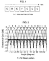
- Fig. 1 is a diagram for describing an example of antenna pattern allocation in a narrow-band system.
- Fig. 2 is a diagram for describing an example of array antenna beam forming.
- Figs. 3A to 3D are diagrams for describing an example of directivity patterns in a spatial plane.
- Fig. 1 represents time and the symbols C to F indicate spatial division multiple access (SDMA) directivity patterns.
- SDMA is a technology in which communication is carried out by utilizing antenna directivity and dividing space. If there is used an array antenna capable of forming 12 separate fixed beams such as shown in Fig. 2 , it is possible to form, as SDMA directivity patterns, four types of directivity patterns creating beam peaks in three directions such as shown in Figs. 3A to 3D . In each of the directivity patterns in Figs. 3A to 3D , three beams are transmitted simultaneously. E.g., in directivity pattern C, beams 1, 5, and 9 are transmitted simultaneously. With beams 1, 5 and 9, the respective beams being oriented toward different terminals and the respective ones transmitting different information.
- directivity pattern C beams 1, 5, and 9 are transmitted simultaneously.
- Fig. 4 is a diagram showing a configuration example of a signal processing part of a base station.
- Fig. 4 shows a configuration example of the transmission part baseband processing simultaneously transmitting at most three signals.
- a network interface 8 is connected with a network, receives information that is gradually transmitted via the network, and stores it in a buffer 7.
- the transmission timing and modulation method for the stored information are determined by a (not illustrated) scheduler.
- the scheduler utilizes channel state information (CSI) reported from a terminal and determines a modulation method in response to information such as CSI quality (C/I) and needs (real time communication or non real time communication).
- CSI channel state information
- C/I CSI quality
- the scheduler determines the transmission timing of each information item on the basis of the order of priority for each session and the CSI.
- the scheduler determines the transmission timing by taking into accounts needs such as whether there is real time communication, based on a scheduling algorithm such as "proportional fairness".
- the scheduler since the beams that can be transmitted are predetermined, as indicated in Fig. 1 , the scheduler, after selecting the users to whom to transmit on the basis of the beams planned for transmission, operates a scheduling algorithm such as "proportional fairness" mentioned above.
- the transmission information in which the modulation method and the timing are determined by the scheduler is extracted from buffer 7 and channel encoding and mapping processing et cetera for 64QAM (64-level Quadrature Amplitude Modulation) or the like is carried out by encoding parts 6.
- multiple encoding parts such as 6-1 to 6-3, are prepared, a maximum of three signals being processed in parallel in the example of Fig. 4 .
- the signals processed by encoding parts 6-1 to 6-3 are next input into channel forming parts 5-1 to 5-3 and additional information such as a packet signal or separate control channels is added.
- channel forming parts 5 there is a channel forming part 5-4 for sending common information within the cell, so four signals are generated simultaneously.
- the respective signals are converted into signals for each antenna in which array weights that are needed for forming beams by downlink beam forming parts 4-1 to 4-4 have been added.
- the same signals are, for each antenna, added and the four signals (three user signals and one common control signal) are combined into one, in a signal combining part 20.
- the combined signals for each antenna are transmitted from an antenna 1 after passing through analog conversion or frequency conversion in an analog front end part 2 and appropriate signal amplification processing has been carried out.
- each beam is designed so that the side lobes are restrained to e.g. -20 dB outside the main beam direction, the D/U (desired-to-undesired) ratio, which is the power ratio between the desired waves and the interference waves, taking on a sufficiently high value.
- the D/U ratio is the power ratio between the desired waves and the interference waves, taking on a sufficiently high value.
- the result is that it is only performing good communication with users in a specific direction. Accordingly, by modifying the SDMA pattern temporally, it becomes possible to communicate with respect to users in the direction of any of the 12 beams. If one returns to Fig. 1 , in this example, the SDMA directivity patterns are changed from C to D, from D to E, from E to F, and from F to C in a determined time interval. If the base station is viewed from above, beams transmitting signals in three directions supply beams to the entire cell while rotating like a propeller turning counter clockwise in response to changes in time.
- Fig. 5 is a diagram for describing an example of antenna pattern allocation in a broad-band system.
- the abscissa represents time and the ordinate represents frequency.
- different directivity patterns are allocated for each frequency and transmission is performed with fixed directivity patterns at specific frequencies.
- Fig. 6 there is shown a configuration example of a signal processing part of a base station simultaneously transmitting beams in three directions, in a broad-band system.
- Fig. 6 is a diagram showing a configuration example of the transmission part baseband processing of an OFDMA-based base station simultaneous transmitting at most N signals.
- Network interface 8 is connected with the network, receives information gradually sent via the network, and stores it in buffer 7.
- the transmission timing and modulation method of the stored information are determined by a (not illustrated) scheduler.
- the modulation method associated with the scheduler the transmission timing, the selection of users to whom to transmit on the basis of the beams planned for transmission, and scheduling operation based on a scheduling algorithm such as "proportional fairness", the contents are the same as those described in Fig. 4 .
- the transmission information determined by the scheduler is extracted from buffer 7 and channel encoding and mapping processing et cetera for 64QAM (64-level Quadrature Amplitude Modulation) or the like is carried out by encoding parts 6.
- multiple encoding parts such as 6-1 to 6-N, are prepared, and in the case of adopting the SDMA patterns of Figs. 3A to 3D , signal processing is executed simultaneously for a maximum of three users at the same frequency.
- the signals processed by encoding parts 6-1 to 6-N are next input into channel forming parts 5-1 to 5-N and additional information such as a packet signal or a separate control channel is added.
- channel forming parts 5-1 to 5-N there is newly added a channel forming part 5-(N+1) for sending common information within the cell.
- the respective signals have array weights that are needed for forming beams by downlink beam forming parts 4-1 to 4-(N+1) added thereto and are converted into signals for each antenna and each sub-carrier.
- a signal combining part 20 the N+1 signals are added and combined into one for each antenna and sub-carrier.
- the combined signals for each antenna and sub-carrier are converted from frequency domain information to time domain information in an IFFT (Inverse Fast Fourier Transform) part 3 to become information for each antenna.
- the time domain signals for each antenna are transmitted from an antenna 1 after passing through analog conversion or frequency conversion in an analog front end part 2 and appropriate signal amplification has been carried out.
- IFFT Inverse Fast Fourier Transform
- a reuse of 1 refers to a situation in which two adjacent base stations utilize the same frequency.
- the C/I ratio on the terminal side is determined by the transmission power from the base station, the interference signal power and the thermal noise power that the terminal has.
- the interference signal power of a certain terminal there are included, in addition to signals from other sectors of the same base station and beams oriented at other users that are formed with the array antenna of the same base station, signals from adjacent base stations. Consequently, on the occasion of allocating antenna patterns to a base station, allocation of antenna patterns also taking into account interference from adjacent base stations becomes necessary.
- the inventors of the present invention have disclosed technology in which, in a system consisting of a plurality of base stations, such as that mentioned in JP-A-2007-243258 , either of two orthogonal directivity patterns is appropriately allocated to each base station on the time axis or the frequency axis. In this way, signal transmission based on a frequency or a time for which interference from adjacent base stations is avoided becomes possible and, based on combination with the scheduler, packet scheduling avoiding strong interference from adjacent base stations becomes possible.
- the present invention is one that, in a wireless communication system in which antenna patterns have already been allocated, offers a method of determining, in the case where a new station is installed, the antenna pattern of the new station so that the state becomes one in which the antenna patterns of the existing base stations adjacent to the new station and of the new station possess orthogonality and the orthogonality between existing base stations is maintained, and has the following characteristics.
- the length and line number of the Walsh function associated with each base station are determined in a control station, which is connected with a plurality of base station devices via the network and making it possible to carry out information exchange with the base stations, and notified to each base station.
- Each base station receiving the Walsh function length and line number from the control station determines, using the same values, an antenna pattern associated with the base station.
- the base station determines the line number of the Walsh matrix on the basis of a number allotted uniquely for each base station, instead of receiving it from the control station.
- the base stations carry out direct communication between themselves and search for antenna patterns that are orthogonal to those of the adjacent base stations.
- Embodiment 1 First, a description of Embodiment 1 will be given.
- Fig. 7 there is shown a configuration example of a wireless communication system in an embodiment of the present invention.
- a plurality of base stations 100, 101 are connected with a network 104.
- the respective base stations have antenna patterns assigned by control from a control station 103.
- control station 103 determines the antenna patterns of base stations 100, 101, and transmits antenna pattern allocation commands and parameters needed for associating antenna patterns with directivity patterns to base stations 100, 101.
- control station 103 there are provided: an antenna pattern allocation table 106 holding data pertaining to antenna pattern allocations et cetera of all base stations; a network interface part 107 using this table; and an antenna pattern allocation table management part 105 carrying out antenna pattern allocation to each base station via network 104.
- Base stations 100, 101 associate antenna patterns with specific directivity patterns on the basis of antenna pattern allocation commands received from control station 103, and parameters, and carry out control of beams transmitted from the antenna.
- Walsh function lengths and line numbers are transmitted as parameters from control station 103 to base stations 100, 101.
- Figs. 8A and 8B are diagrams showing examples of directivity patterns in Embodiment 1 of the present invention.
- Embodiment 1 a description is given for a system in which six beams, from among twelve beams, are transmitted simultaneously.
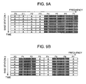
- Figs. 9A and 9B are diagrams describing antenna patterns of two adjacent base stations in Embodiment 1.
- Fig. 9A shows a beam directivity pattern pertaining to base station 1.
- the abscissa represents frequency, there being prepared eight frequency channels, from F0 to F7.
- the ordinate represents time and indicates that the beam directivity patterns do not change over time.
- Reference A or B in the boxes indicates a situation in which a signal is transmitted at a corresponding frequency using antenna directivity pattern A or antenna directivity pattern B shown in Figs. 8A and 8B .
- the SDMA directivity patterns are set to differ by frequency among adjacent base stations. By making a decision in this way so that the directivity patterns differ for each frequency between adjacent base stations, it is possible to randomize the influence of interference beams from adjacent stations.
- this user preferentially utilizes F1 or F2, he can communicate avoiding the influence from the adjacent base station.
- frequencies other than these it is not possible to obtain good communication quality because there occur things like the signal expected from base station 1 not arriving or the interference signal from base station 2 being strong.
- the directivity pattern of the antenna for each frequency to generate a good situation in which interference does not occur and a deteriorated situation in which interference occurs strongly is called randomization. After randomization has been carried out, interference avoidance is carried out by selectively by using good frequencies at which interference does not occur.
- the scheduler carries out channel allocation in response to the channel state, it is possible, by preferentially selecting a frequency (or a time) at which interference is small, to avoid interference. As a result of allocating frequencies for each terminal for which interference is difficult to receive, it is possible to enhance the communication capacity for the whole base station and also, for the entire communication system.
- antenna pattern A (1, 3, 5, 7, 9, and 11) and antenna pattern B (2, 4, 6, 8, 10, and 12) indicate directivity patterns in which a signal is simultaneously transmitted in respectively six directions.
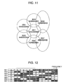
- Fig. 10 there is shown an example in which antenna patterns are allocated to a plurality of base stations using a Walsh function.
- the circles of Fig. 10 indicate the service area (cell) of each base station. Base stations are arranged at the centers of the circles. A description will e.g. be given for the cell in the center of the diagram that is marked with "d". The mention "AAAABBBB” listed within the cell indicates, as mentioned at the bottom right, the correspondence of frequencies and directivity patterns. What are shown are the directivity patterns in each frequency band, in ascending order of frequencies from the left.
- Pattern d This combination of frequencies and directivity patterns is called "Pattern d". If one looks at the periphery of Pattern d, combined patterns other than Pattern d enclose the perimeter, Pattern d not being present in the cells adjacent to the Pattern d cell. If one looks at one pattern of the surrounding cells, in e.g. "Pattern a", the antenna patterns take on combinations that differ from Pattern d, as follows:
- the directivity patterns in the case of two independent patterns such as shown in Figs. 8A and 8B , the antenna pattern design is completed by substituting directivity pattern A for "1" and directivity pattern B for "0". That is to say that they are "AABB”, "ABBA”, and "ABAB".
- Fig. 11 there is shown the antenna pattern of each cell before a new station is added, in Embodiment 1.
- BS1 whose cell is adjacent to six cells.
- Fig. 12 there is shown a diagram where the antenna pattern of each cell in Fig. 11 is displayed on the frequency axis.
- the ordinate represents base stations BS1 to BS7 and the abscissa represents the directivity pattern allocation for each frequency in each base station.
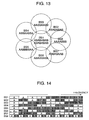
- the cell of BS8 is additionally installed to be adjacent to the respective cells of BS1, BS2, and BS7, which are existing base stations.
- Fig. 13 there is shown a base station antenna pattern after the new station has been added.
- the number of adjacent cells of BS1 is increased from 6 to 7, as shown in Fig. 13 .
- antenna pattern allocation is in the same way carried out for a second time, in case the number of adjacent cells after the increase exceeds the maximum number of adjacent cells that is possible with allocation with the Walsh function used for the current antenna pattern allocation.
- Fig. 14 there is shown an allocation of antenna patterns to each cell after the new station has been installed additionally.
- the antenna pattern allocation result with respect to each frequency of each BS after BS8, the new station, has been installed additionally is as shown in Fig. 14 . It is seen that hereby, a new station installation is implemented in a state in which the newly additionally installed base station possesses antenna pattern orthogonality with adjacent existing base stations and the orthogonality among existing base stations is also maintained.
- Fig. 15 there is shown a configuration example of an antenna pattern allocation table of the control station.
- Antenna pattern allocation table 106 of the control station is composed of: a base station number 200 that is allocated to a base station for the purpose of identifying each base station in a wireless communication system; base station coordinates 201 taking as their reference the antenna position of the same base station; the Walsh function 202 with length N that is currently applied for the antenna pattern allocation of the same base station; and a matrix line number L 203. Further, the range of line numbers L is 1 to N-1.
- antenna pattern allocation table management part 105 executes the base station number and coordinate information of the base station to be newly installed.
- the information about the additional installation of a base station is received (Step 300)
- the received base station number and coordinate information about the new station is registered in an antenna pattern allocation table 106 (Step 301).
- Step 302 the antenna pattern allocation process is carried out with respect to the new station.
- a description regarding the present process will be given using Fig. 17 .
- antenna pattern allocation table 106 is looked up and the distance between the coordinates of the new station and the base station coordinates listed in the table is calculated, a base station being considered as an adjacent base station if the distance between the base stations is equal to or less than a value obtained by multiplying the minimum distance to a base station by a fixed index (e.g. 1.5), and the number C BSa of base stations that will be adjacent is counted (Step 401).
- a fixed index e.g. 1.5
- the Walsh functions used on the periphery are only ones having a length of 8, as shown in Fig. 14 , even if any line of a newly created Walsh function with length 16 is used, it can be made to be orthogonal with the other functions. In case e.g. a series of first and fourth lines of a Walsh function with length 16 is already used in adjacent stations, it is avoided to select the same lines, and by selecting e.g. the second line, it is possible to implement an allocation that is orthogonal with any of the base station antenna patterns on the periphery.
- the Walsh function length N BSt and line number L BSt found above are registered (Step 407) and a command is given (Step 408) with respect to the new station via network interface part 107 and network 104 to carry out the antenna pattern allocation with a Walsh function of length N BSt and line number L BSt .
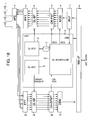
- Fig. 18 there is shown a configuration example of a signal processing part of a base station for implementing Embodiment 1.
- the network interface of the base station receives antenna pattern allocation commands gradually sent from antenna pattern allocation table management part 105 of control station 103 via the network and information about the length and line number of the Walsh function used for the antenna pattern allocation of the base station.
- Network interface 8 inputs the received information to a DSP 9 carrying out control of the scheduler and the like.
- the signal received by an antenna 1 is converted into a baseband signal in an analog front end 2 and is converted to the frequency domain in an FFT part 14 carrying out FFT computations with suitable timing.
- the frequency domain information is beam formed by means of adaptive control in an uplink beam forming part 15. However, even in the uplink, a fixed beam may be used.
- the array weights for beam forming are calculated by a beam forming control part 12.
- a pilot signal and the like are separated by means of a channel separation part 16, detection, de-mapping, and channel decoding are carried out by a decoding part 17, and the signal becomes user information.
- the obtained information is sent to the network via network interface 8.
- Channel separation part 16 also separates MAC information such as CSI, ACK, and the like, apart from the pilot signal.
- CSI is the downlink channel quality measured by the terminal. In CSI, it is reported which beam has good quality, which frequency has good quality and also, what the SINR (Signal to Interference + Noise Ratio) thereof are. "ACK" indicates the error detection result of the previously transmitted packet in the downlink circuit.
- DSP 9 defines beams to be transmitted at specific frequencies. In addition, it uses downlink quality information (CSI) reported from each user and, with corresponding beams of corresponding frequencies, selects users with good characteristics, and carries out scheduling to determine packet transmission. Also, in the scheduling, the modulation method (MCS: Modulation and Coding Scheme) of the information to be transmitted to the corresponding users is determined from SINR and ACK information, out of the pieces of quality information from the terminal.
- CSI downlink quality information
- MCS Modulation and Coding Scheme
- the information about users for whom transmission has been decided is extracted from buffer 7 and is transferred to modulation block 6.
- channel coding and modulation of the information is performed, in accordance with the modulation method decided by the packet scheduler.
- additional signals such as a pilot signal for demodulation are added in channel forming part 5 and frame formatting is arranged.
- Information with completed frame formatting has fixed beam array weights attached by downlink beam forming part 4 and a beam such as shown in the example of Fig. 3 is formed into a signal that can be transmitted.
- the array weights attached at this stage for each antenna are ones selected by downlink beam forming control part 10.
- the array weights in this embodiment have a fixed value that is stored in a memory 11.
- a signal which is the output of downlink beam forming part 4 and for which beam forming processing has been implemented for each antenna, becomes information for each antenna that is converted from frequency domain information into time domain information.
- Embodiment 1 it is possible, in the case where a new station is added inside a wireless communication system, for the control station to easily carry out antenna pattern allocation with respect to existing base stations for which reallocation has become necessary due to the fact that the number of new stations and adjacent base stations has increased.
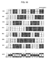
- Embodiment 2 will be described using Fig. 19 .
- Embodiment 1 the fact, accompanying the addition of a new station, of increasing the length N of the Walsh functions, increasing the antenna patterns, and carrying out a reallocation of antenna patterns to existing base stations for which the number of adjacent base stations has increased was also described in Embodiment 1. Since the antenna patterns are increased following the increase in the length N of the Walsh functions, in Embodiment 1, there was shown an embodiment in which the number of frequency divisions was doubled. In Embodiment 2, a description will be given regarding an embodiment in which antenna patterns are increased in the time axis direction without changing the number of frequency divisions.
- Fig. 19 is a diagram showing an example of an antenna pattern allocation to each base station in Embodiment 2.
- the ordinate direction represents time and the abscissa direction represents frequency, the antenna pattern allocation for each time and frequency associated with each base station being indicated.
- Embodiment 2 by changing the antenna patterns not only in the frequency direction but also in the time direction, an increase in antenna patterns accompanying an increase in the length N of the Walsh functions is handled without reducing the bandwidth.
- N 32 Walsh function
- it is possible to generate antenna patterns for 31 stations with an N 32 Walsh function. If these 32 channels are considered as one block, there necessarily exists for the user a frequency or time at which the influence due to interference beams from other stations is avoided at some frequency or time within the block by making the scheduling so that such a channel is selected, so the avoidance of influence of interference beams from other stations becomes possible.
- a Walsh function with a length N capable of generating a sufficiently larger number of antenna patterns than the number of cells adjacent to a certain base station so by carrying out antenna pattern allocation to each base station from a sufficiently large number of antenna patterns, the number of new stations and adjacent base stations increases with respect to base stations for which reallocation of antenna patterns is possible and antenna allocation is easily possible, even in the case where a new station is installed additionally.
- the selection of Walsh functions used for the allocation of antenna patterns to each base station may be carried out by relating each base station with a uniquely allocated number.
Landscapes
- Engineering & Computer Science (AREA)
- Signal Processing (AREA)
- Computer Networks & Wireless Communication (AREA)
- Mobile Radio Communication Systems (AREA)
Applications Claiming Priority (1)
| Application Number | Priority Date | Filing Date | Title |
|---|---|---|---|
| JP2009211251A JP5331632B2 (ja) | 2009-09-14 | 2009-09-14 | 無線通信システムおよび無線通信方法ならびに基地局 |
Publications (1)
| Publication Number | Publication Date |
|---|---|
| EP2299622A2 true EP2299622A2 (fr) | 2011-03-23 |
Family
ID=43532995
Family Applications (1)
| Application Number | Title | Priority Date | Filing Date |
|---|---|---|---|
| EP10006640A Withdrawn EP2299622A2 (fr) | 2009-09-14 | 2010-06-25 | Système de communication sans fil, procédé de communication sans fil et station de base |
Country Status (3)
| Country | Link |
|---|---|
| US (1) | US8571589B2 (fr) |
| EP (1) | EP2299622A2 (fr) |
| JP (1) | JP5331632B2 (fr) |
Families Citing this family (5)
| Publication number | Priority date | Publication date | Assignee | Title |
|---|---|---|---|---|
| US8326250B2 (en) * | 2008-05-22 | 2012-12-04 | Broadcom Corporation | Receiver with statistical analysis and methods for use therewith |
| JP2013251841A (ja) * | 2012-06-04 | 2013-12-12 | Hitachi Ltd | 無線通信基地局 |
| US9661612B2 (en) * | 2012-06-29 | 2017-05-23 | Samsung Electronics Co., Ltd. | Methods and apparatus for uplink control channel multiplexing in beamformed cellular systems |
| KR102445061B1 (ko) * | 2014-08-06 | 2022-09-19 | 인터디지탈 패튼 홀딩스, 인크 | 장치-대-장치 송신 패턴을 결정하기 위한 방법 및 장치 |
| US11438050B2 (en) * | 2020-05-01 | 2022-09-06 | Fujikura Ltd. | Wireless communication system |
Citations (1)
| Publication number | Priority date | Publication date | Assignee | Title |
|---|---|---|---|---|
| JP2007243258A (ja) | 2006-03-06 | 2007-09-20 | Hitachi Ltd | 無線通信方式および無線基地局装置 |
Family Cites Families (4)
| Publication number | Priority date | Publication date | Assignee | Title |
|---|---|---|---|---|
| US4590608A (en) * | 1980-05-30 | 1986-05-20 | The United States Of America As Represented By The Secretary Of The Army | Topographic feature extraction using sensor array system |
| US4635221A (en) * | 1985-01-18 | 1987-01-06 | Allied Corporation | Frequency multiplexed convolver communication system |
| US7751367B2 (en) * | 2003-12-11 | 2010-07-06 | Qualcomm, Inc. | Conveying sector load information to mobile stations |
| JP4559270B2 (ja) * | 2005-03-22 | 2010-10-06 | 株式会社日立製作所 | 無線通信システム |
-
2009
- 2009-09-14 JP JP2009211251A patent/JP5331632B2/ja not_active Expired - Fee Related
-
2010
- 2010-06-25 EP EP10006640A patent/EP2299622A2/fr not_active Withdrawn
- 2010-06-29 US US12/826,140 patent/US8571589B2/en not_active Expired - Fee Related
Patent Citations (1)
| Publication number | Priority date | Publication date | Assignee | Title |
|---|---|---|---|---|
| JP2007243258A (ja) | 2006-03-06 | 2007-09-20 | Hitachi Ltd | 無線通信方式および無線基地局装置 |
Also Published As
| Publication number | Publication date |
|---|---|
| JP5331632B2 (ja) | 2013-10-30 |
| JP2011061647A (ja) | 2011-03-24 |
| US8571589B2 (en) | 2013-10-29 |
| US20110092238A1 (en) | 2011-04-21 |
Similar Documents
| Publication | Publication Date | Title |
|---|---|---|
| JP5295977B2 (ja) | ワイヤレス通信システムにおける同一チャネル干渉の特徴付け | |
| JP5557712B2 (ja) | アンテナ送信電力制御を行う無線基地局装置 | |
| JP4753750B2 (ja) | 無線通信方式および無線基地局装置 | |
| EP2346201B1 (fr) | Procédé et système pour transmission MU-MIMO | |
| CA2780353C (fr) | Ameliorations apportees a un procede et a un appareil servant a la co-planification des emissions dans un reseau radio | |
| WO2011052273A1 (fr) | Signalisation de commande de liaison descendante pour une opération d'entrées multiples/de sorties multiples (mimo) de liaison descendante | |
| US20100329199A1 (en) | Wireless communication system, base station , resource block allocation method, and program | |
| US20140086205A1 (en) | Base station and method of allocating radio resource | |
| US10673652B2 (en) | System and method for providing explicit feedback in the uplink | |
| JP6518021B1 (ja) | 無線通信装置および無線通信方法 | |
| US8571589B2 (en) | Wireless communication system, wireless communication method, and base station | |
| KR102286877B1 (ko) | 필터뱅크 기반의 멀티 캐리어 신호 송수신을 위한 필터 재사용 방법 | |
| CN103548286A (zh) | 用于无线系统中的功率分配的方法和基站 | |
| JP5603288B2 (ja) | 無線通信システム、無線通信方法および基地局装置 | |
| JP5107337B2 (ja) | 移動通信システムで使用される基地局及び方法 | |
| JP5199820B2 (ja) | 端末局装置および通信システム | |
| CN110050451A (zh) | 导频序列发生器及相应的方法和信道估计器及相应的方法 | |
| JP5262332B2 (ja) | 無線通信システム、基地局装置、及び無線端末装置 | |
| JP2011009871A (ja) | Mimo−ofdmaシステムにおけるチャネル割り当て方法及びチャネル割り当て装置 | |
| JP5528179B2 (ja) | 基地局装置、基地局装置の制御プログラムおよび集積回路 | |
| JP5275374B2 (ja) | 複数のアンテナを用いて端末と周波数多重通信を行なう基地局と、基地局とネットワークを介して接続される制御局 | |
| Wu et al. | Adaptive SIMO and SDMA transmission mode for single carrier FDMA uplink | |
| JP2019201403A (ja) | 無線通信装置 | |
| WO2016029971A1 (fr) | Modulation de porteuse en communications |
Legal Events
| Date | Code | Title | Description |
|---|---|---|---|
| PUAI | Public reference made under article 153(3) epc to a published international application that has entered the european phase |
Free format text: ORIGINAL CODE: 0009012 |
|
| AK | Designated contracting states |
Kind code of ref document: A2 Designated state(s): AL AT BE BG CH CY CZ DE DK EE ES FI FR GB GR HR HU IE IS IT LI LT LU LV MC MK MT NL NO PL PT RO SE SI SK SM TR |
|
| AX | Request for extension of the european patent |
Extension state: BA ME RS |
|
| 17P | Request for examination filed |
Effective date: 20120329 |
|
| STAA | Information on the status of an ep patent application or granted ep patent |
Free format text: STATUS: THE APPLICATION HAS BEEN WITHDRAWN |
|
| 18W | Application withdrawn |
Effective date: 20150115 |