EP2298689B1 - Verfahren und Vorrichtung zur Lastmomentbegrenzung eines Ladekrans - Google Patents
Verfahren und Vorrichtung zur Lastmomentbegrenzung eines Ladekrans Download PDFInfo
- Publication number
- EP2298689B1 EP2298689B1 EP10177616.9A EP10177616A EP2298689B1 EP 2298689 B1 EP2298689 B1 EP 2298689B1 EP 10177616 A EP10177616 A EP 10177616A EP 2298689 B1 EP2298689 B1 EP 2298689B1
- Authority
- EP
- European Patent Office
- Prior art keywords
- crane
- value
- lorry
- bas
- lifting
- Prior art date
- Legal status (The legal status is an assumption and is not a legal conclusion. Google has not performed a legal analysis and makes no representation as to the accuracy of the status listed.)
- Active
Links
- 238000000034 method Methods 0.000 title claims description 10
- 230000001105 regulatory effect Effects 0.000 claims description 31
- 230000005484 gravity Effects 0.000 claims description 5
- 230000000087 stabilizing effect Effects 0.000 description 19
- 239000012530 fluid Substances 0.000 description 4
- 238000006243 chemical reaction Methods 0.000 description 2
- 230000001276 controlling effect Effects 0.000 description 2
- 238000006073 displacement reaction Methods 0.000 description 2
- 238000012544 monitoring process Methods 0.000 description 2
- 239000000725 suspension Substances 0.000 description 2
- 230000001419 dependent effect Effects 0.000 description 1
- 230000002349 favourable effect Effects 0.000 description 1
- 238000012986 modification Methods 0.000 description 1
- 230000004048 modification Effects 0.000 description 1
Images

Classifications
-
- B—PERFORMING OPERATIONS; TRANSPORTING
- B66—HOISTING; LIFTING; HAULING
- B66C—CRANES; LOAD-ENGAGING ELEMENTS OR DEVICES FOR CRANES, CAPSTANS, WINCHES, OR TACKLES
- B66C23/00—Cranes comprising essentially a beam, boom, or triangular structure acting as a cantilever and mounted for translatory of swinging movements in vertical or horizontal planes or a combination of such movements, e.g. jib-cranes, derricks, tower cranes
- B66C23/88—Safety gear
- B66C23/90—Devices for indicating or limiting lifting moment
- B66C23/905—Devices for indicating or limiting lifting moment electrical
-
- B—PERFORMING OPERATIONS; TRANSPORTING
- B66—HOISTING; LIFTING; HAULING
- B66C—CRANES; LOAD-ENGAGING ELEMENTS OR DEVICES FOR CRANES, CAPSTANS, WINCHES, OR TACKLES
- B66C13/00—Other constructional features or details
- B66C13/18—Control systems or devices
- B66C13/40—Applications of devices for transmitting control pulses; Applications of remote control devices
-
- B—PERFORMING OPERATIONS; TRANSPORTING
- B66—HOISTING; LIFTING; HAULING
- B66C—CRANES; LOAD-ENGAGING ELEMENTS OR DEVICES FOR CRANES, CAPSTANS, WINCHES, OR TACKLES
- B66C23/00—Cranes comprising essentially a beam, boom, or triangular structure acting as a cantilever and mounted for translatory of swinging movements in vertical or horizontal planes or a combination of such movements, e.g. jib-cranes, derricks, tower cranes
- B66C23/54—Cranes comprising essentially a beam, boom, or triangular structure acting as a cantilever and mounted for translatory of swinging movements in vertical or horizontal planes or a combination of such movements, e.g. jib-cranes, derricks, tower cranes with pneumatic or hydraulic motors, e.g. for actuating jib-cranes on tractors
-
- B—PERFORMING OPERATIONS; TRANSPORTING
- B66—HOISTING; LIFTING; HAULING
- B66C—CRANES; LOAD-ENGAGING ELEMENTS OR DEVICES FOR CRANES, CAPSTANS, WINCHES, OR TACKLES
- B66C23/00—Cranes comprising essentially a beam, boom, or triangular structure acting as a cantilever and mounted for translatory of swinging movements in vertical or horizontal planes or a combination of such movements, e.g. jib-cranes, derricks, tower cranes
- B66C23/62—Constructional features or details
- B66C23/72—Counterweights or supports for balancing lifting couples
- B66C23/78—Supports, e.g. outriggers, for mobile cranes
Definitions
- the present invention relates to a lorry according to the preamble of claim 1 as known from JP 2007 314257 A and a method for regulating the maximum allowed lifting moment of a hydraulic lorry crane.
- base value is in the following used as a denomination for this maximum allowed value for the lifting moment of the crane established based on the strength properties of the crane.
- This base value may be a fixed value which takes into account the position of the crane boom system which, with respect to strength, is the most critical one among the allowed positions for the crane boom system of the crane, or a variable value established instantaneously in dependence on the swing-out angle of the inner boom of the crane and possibly further variables defining the prevailing position of the crane boom system of the crane.
- the value for the maximum allowed lifting moment is normally converted into a corresponding value for the maximum allowed working pressure for the lifting cylinder of the crane, and by limiting this working pressure it is secured that the lifting moment of the crane will not exceed the maximum allowed lifting moment.
- the value of the maximum allowed lifting moment also has to be adapted in dependence on the stability of the lorry, to thereby avoid a tipping of the lorry due to inappropriate manoeuvring of the crane.
- the tipping moment presently exerted on the lorry by the crane and by the load carried by the crane has to be lower than the stabilizing moment given by the weight of the lorry without cargo in combination with the weight of the possible load located on the lorry.
- the magnitude of the tipping moment and the stabilizing moment depends i.a. on the position of the tipping line over which the crane boom system of the crane presently extends. In dependence on the position of the support legs of the lorry and the horizontal slewing position of the crane, this tipping line may extend between two vehicle wheels, between two support legs or between one vehicle wheel and one support leg.
- the position of the tipping line can be established based on information about the slewing angle of the column of the crane and information about the horizontal extension length of the support legs of the lorry.
- the perpendicular distance between the tipping line and the centre of gravity of the lorry without cargo can be calculated, which in its turn makes it possible to calculate the stabilizing moment given by the weight of the lorry without cargo.
- the perpendicular distance between the tipping line and the load suspension point of the crane can be calculated, which in its turn makes it possible to estimate the tipping moment exerted by the crane when the lifting moment of the crane corresponds to the above-mentioned base value for the maximum allowed lifting moment.
- a lorry normally lacks a sensor for establishing the prevailing wheel force of the load-bearing vehicle wheels of the lorry, which implies that there is no possibility to calculate the stabilizing moment given by the load presently located on the lorry.
- the stabilizing moment given by the weight of the lorry without cargo is therefore taken into account, and it will thereby not be possible to adapt the lifting capacity of the crane in dependence on the stabilizing moment given by the weight of the possible load presently located on the lorry.
- the tipping moment M O exerted by the crane when the lifting moment of the crane corresponds to the above-mentioned base value M C,bas for the maximum allowed lifting moment and the stabilizing moment M S given by the weight of the lorry without cargo are calculated in the manner described above. Thereafter, it is checked whether a predetermined stability condition is fulfilled with these tipping and stabilizing moments, namely whether the ratio between the stabilizing moment M S and the tipping moment M O is equal to or larger than the value of a given stability constant k ( M S / M O ⁇ k ). If the stability condition is fulfilled, i.e.
- M S / M O ⁇ k said base value M C,bas is used as an upper limit for the allowed lifting moment of the crane.
- the reduced value M C,red is then used as an upper limit for the maximum allowed lifting moment of the crane.
- JP 2008 074561 A discloses a lorry provided with a hydraulic crane and support legs.
- the ground contact reaction force of each support leg is detected and a warning signal is emitted when the ground contact reaction force of a support leg is below a predetermined threshold value.
- the threshold value is reduced when the horizontal extension length of the support leg is increased.
- the object of the present invention is to provide a new and favourable manner for regulating the maximum allowed lifting moment of a hydraulic lorry crane.
- said object is achieved by means of a lorry having the features defined in claim 1 and a method having the features defined in claim 7.
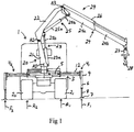
- Figs 1 and 2 show a lorry 1 provided with load-bearing vehicle wheels 2 1 -2 4 and a chassis 3 supported by the vehicle wheels.
- the lorry is provided with two rear wheels 2 1 , 2 2 and two front wheels 2 3 , 2 4 , but the lorry could also be provided with a larger number of load-bearing vehicle wheels than here illustrated.
- a hydraulic crane 20 is mounted on and carried by the chassis 3.
- Two horizontally extendable support legs 4 1 , 4 3 are arranged on one side of the longitudinal axis of the vehicle, and two horizontally extendable support legs 4 2 , 4 4 are arranged on the opposite side of the longitudinal axis of the vehicle.
- the lorry could alternatively be provided with a larger or smaller number of support legs than here illustrated.
- the respective support leg 4 1 -4 4 has a first force member 5, suitably in the form of a hydraulic cylinder, by means of which the support leg is horizontally displaceable from a retracted position close to the chassis 3 to an extended position at a distance from the chassis 3.
- the respective support leg 4 1 -4 4 could be manually displaceable horizontally from a retracted position close to the chassis 3 to an extended position at a distance from the chassis 3.
- the support legs 4 1 -4 4 are shown in the extended position in Figs 1 and 2 .
- the respective support leg 4 1 -4 4 has a second force member 6, by means of which the support leg is manoeuvrable to an active support position in contact with the ground or other underlayer.
- the support legs 4 1 -4 4 are shown in the active support position in Figs 1 and 2 .
- the respective support leg rests against the underlayer through a support leg foot 7 arranged at the lower end of a telescopically lowerable lower support leg part 8 of the support leg.
- the second force member 6 consists of a hydraulic cylinder, by means of which the lower support leg part 8 of the support leg is displaceable upwards and downwards in relation to an upper support leg part 9.
- the lorry 1 comprises means 10 (schematically indicated in Fig 4 ) for establishing the horizontal extension length of the respective support leg 4 1 -4 4 .
- These means 10 comprise sensors which sense the displacement position of the horizontally displaceable part 12 of the respective support leg or the displacement position of the movable part of said first force member 5 of the respective support leg.
- the lorry 1 comprises means 11 (schematically indicated in Fig 4 ) for establishing the force F exerted by the second force member 6 of the respective support leg 4 1 -4 4 when the support leg is in the active support position.
- This force corresponds to the contact force exerted by the support leg against the underlayer and consequently the normal force acting on the support leg from the underlayer.
- the means 11 comprise pressure sensors for sensing the differential pressure of each one of these hydraulic cylinders.
- the hydraulic lorry crane 20 comprises:
- the slewing angle ⁇ of the column 21 in relation to the chassis 3 is established by means of a sensor 14 (schematically indicated in Fig 4 ), which continuously senses the slewing position of the column.
- the crane 20 also comprises a liftable and lowerable crane boom 24, here denominated outer boom, which is articulately fastened to the inner boom 22 in such a manner that it is turnable in relation to the inner boom about an essentially horizontal axis of rotation A3.
- a hydraulic cylinder 25, here denominated outer boom cylinder carries out the lifting and lowering of the outer boom 24 in relation to the inner boom 22.
- the crane boom system 29 of the crane is formed by the inner boom 22 and the outer boom 24.
- the lifting cylinder 23 comprises a cylinder part 23a which is articulately fastened to the column 21, and a piston which is received in this cylinder part and displaceable in relation to it, the piston being provided with a piston rod 23b, which is articulately fastened to the inner boom 22.
- the outer boom cylinder 25 comprises a cylinder part 25a which is articulately fastened to the inner boom 22, and a piston which is received in this cylinder part and displaceable in relation to it, the piston being provided with a piston rod 25b, which is articulately fastened to the outer boom 24.
- the outer boom 24 comprises two crane boom sections 24a, 24b which are mutually displaceable in the longitudinal direction of the outer boom for adjustment of the extension length of the outer boom.
- the crane boom sections 24a, 24b are displaceable in relation to each other by means of a hydraulic cylinder 26 carried by the outer boom 24.
- a rotator 27 is articulately fastened to the outer end of the outer boom, which rotator in its turn carries a lifting hook 28.
- a liftable and lowerable crane boom in the form of a so-called jib may be mounted to the outer end of the outer boom 24.
- the crane 20 further comprises an electronic regulating device 30 (schematically indicated in Fig 4 ), which is adapted to check whether one or more predetermined stability conditions for the lorry are fulfilled with a lifting moment of the crane corresponding to a, with respect to the strength of the crane, maximum allowed value M C,bas , here denominated base value, for the lifting moment of the crane.
- an electronic regulating device 30 (schematically indicated in Fig 4 ), which is adapted to check whether one or more predetermined stability conditions for the lorry are fulfilled with a lifting moment of the crane corresponding to a, with respect to the strength of the crane, maximum allowed value M C,bas , here denominated base value, for the lifting moment of the crane.
- This base value M C,bas may be a given fixed value which takes into account the position of the crane boom system which, with respect to strength, is the most critical one among the allowed positions for the crane boom system 29 of the crane, or a variable value established by the regulating device 30 in dependence on the swing-out angle of the inner boom 22 of the crane in the vertical plane and possibly further variables defining the prevailing position of the crane boom system of the crane.
- the regulating device 30 is adapted to establish a reduced value M C,red for the maximum allowed lifting moment of the crane, the regulating device 30 being adapted, when establishing this reduced value M C,red , to take into account the horizontal extension length of the respective support leg 4 1 -4 4 that is in the active support position, the slewing angle ⁇ of the column 21 in relation to the chassis 3 in the horizontal plane, and the force F i exerted by the second force member 6 of the respective support leg that is in the active support position and is not included in the prevailing tipping line of the lorry. A preferred implementation of this will be described in the following.
- the support legs 4 1 -4 4 are not designed to carry the entire weight of the lorry when the crane 20 is used.
- the main part of the weight of the lorry is carried by the vehicle wheels 2 1 -2 4
- the support legs 4 1 -4 4 that are in the active support position only carry a minor part of the weight of the lorry.
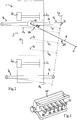
- the position of the prevailing tipping line L O (see Fig 2 ), i.e. the position of the tipping line over which the lorry 1 presently runs the risk of tipping in case of an overloading of the crane 20, depends on the prevailing slewing position of the crane boom system 29 in the horizontal plane and the horizontal extension length of the support legs 4 1 -4 4 that are in the active support position.
- the slewing angle ⁇ of the column 21 in relation to the chassis 3 and the horizontal extension length of the respective support leg 4 1 -4 4 , it will consequently be possible to establish the position of the prevailing tipping line L O .
- the angle ⁇ ' between the crane boom system 29 and the normal to the tipping line can then be established, as well as the perpendicular distance H between the vertical axis of rotation A1 of the crane and the prevailing tipping line L O .
- R is the lifting radius of the crane, i.e. the horizontal distance from the vertical axis of rotation A1 of the crane to the load suspension point P.
- the lifting radius R can be calculated based on measured values on the variables defining the prevailing position of the crane booms 22, 24 of the crane.
- the lifting radius R may alternatively be set to a fixed value representing the largest possible lifting radius of the crane.
- m v ⁇ g ⁇ h v the moment from the known mass of the unloaded lorry
- m e ⁇ g ⁇ h e the moment from the unknown mass of the possible load.
- the conventional stability condition that the ratio between the stabilizing moment M S and the tipping moment M O is to be larger than or equal to the value on a stability constant k with a given value higher than 1, for instance 1.2, may be used as stability condition.
- This stability condition can consequently be written in the following manner: M S M O ⁇ k
- the regulating device 30 is adapted to establish the above-mentioned reduced value M C,red for the maximum allowed lifting moment of the crane as the product of the base value M C,bas and a reduction factor ⁇ which is established by the regulating device and has a value lower than 1.
- the regulating device 30 is adapted to make said reduction factor ⁇ assume an increased value ⁇ eh , which is higher than said basic value ⁇ bas .
- the regulating device 30 is in a conventional manner adapted to convert the prevailing value ( M C,bas or M C,red ) for the maximum allowed lifting moment of the crane 20 into a corresponding value for the maximum allowed working pressure for the lifting cylinder 23.
- the control system for controlling the different crane functions i.e. lifting/lowering by means of the lifting cylinder 23, tilting by means of the outer boom cylinder 25, extension/retraction by means of the hydraulic cylinder 26 etc, comprises a pump 40 (see Fig 4 ), which pumps hydraulic fluid from a reservoir 41 to a directional-control-valve block 42.
- the directional-control-valve block 42 comprises a directional-control-valve section 43 for each of the hydraulic cylinders 23, 25 and 26 of the crane boom system, to which hydraulic cylinders hydraulic fluid is supplied in a conventional manner in dependence on the setting position of the slide member in the respective directional-control-valve section 43.
- the setting position of the slide members in the directional-control-valve sections 43 is controlled either through a number of manoeuvring members, for instance in the form of manoeuvring levers 44, each of which being connected to its own slide member, or by remote control through a manoeuvring unit 45 (see Fig 3 ) comprising a manoeuvring member S1-S6 for each slide member.
- control signals are transmitted through cable or a wireless connection from the manoeuvring unit 45 to an electronic control unit, for instance in the form of a microprocessor, which in its turn controls the setting position of the slide members in the valve sections 43 of the directional-control-valve block 42 in dependence on the magnitude of the respective control signal from the manoeuvring unit 45.
- an electronic control unit for instance in the form of a microprocessor, which in its turn controls the setting position of the slide members in the valve sections 43 of the directional-control-valve block 42 in dependence on the magnitude of the respective control signal from the manoeuvring unit 45.
- Each individual directional-control-valve section 43 consequently controls the magnitude and the direction of the flow of hydraulic fluid to a specific hydraulic cylinder and thereby controls a specific crane function.
- Fig 4 For the sake of clarity, only the directional-control-valve section 43 for the lifting cylinder 23 is illustrated in Fig 4 .
- the directional-control-valve block 42 further comprises a shunt valve 46, which pumps excessive hydraulic fluid back to the reservoir 41, and an electrically controlled dump valve 47, which can be made to return the entire hydraulic flow from the pump 40 directly back to the reservoir 41.
- the directional-control-valve block 42 is of load-sensing and pressure-compensating type, which implies that the magnitude of the hydraulic flow supplied to a hydraulic cylinder is always proportional to the position of the slide member in the corresponding directional-control-valve section 43, i.e. proportional to the setting position of the manoeuvring lever 44.
- the directional-control-valve section 43 comprises a pressure limiter 48, a pressure compensator 49 and a directional-control-valve 50.
- Directional-control-valve blocks and directional-control-valve sections of this type are known and available on the market. Also other types of valve devices than the one here described may of course be used in the crane 20 in question.
- a load holding valve 51 is arranged between the respective hydraulic cylinder and the associated directional-control-valve section 43, which load holding valve makes sure that the load will remain hanging when the hydraulic system runs out of pressure when the dump valve 47 is made to return the entire hydraulic flow from the pump 40 directly back to the reservoir 41.
- the crane further comprises a pressure sensor 52 arranged to measure the hydraulic pressure on the piston side of the lifting cylinder 23.
- the regulating device 30 is connected to the pressure sensor 52 in order to receive measuring signals from this sensor related to said hydraulic pressure.
- the regulating device 30 continuously reads the output signal from the pressure sensor 52 and compares this output signal with the established value for the maximum allowed working pressure for the lifting cylinder 23. If the pressure sensed by the pressure sensor 52 exceeds the established maximum allowed working pressure for the lifting cylinder 23, the regulating device 30 delivers a signal to the dump valve 47 which dumps the hydraulic flow directly to the reservoir 41, which results in that the hydraulic system runs out or pressure and the load is held in its position by means of the load holding valve 51. In this situation, the control system is adapted to allow only moment reducing crane movements.
- the regulating device 30 is adapted to let the maximum allowed working pressure for the lifting cylinder 23 represent the maximum allowed hydraulic pressure on the piston side of the lifting cylinder.
- the regulating device 30 could alternatively be adapted to let the maximum allowed working pressure for the lifting cylinder 23 represent the maximum allowed differential pressure in the hydraulic cylinder.
- This differential pressure is defined as the hydraulic pressure on the piston side of the lifting cylinder minus the hydraulic pressure on its piston rod side divided by the cylinder ratio.
- the regulating device 30 is also arranged to receive measuring signals from a pressure sensor 53 which measures the hydraulic pressure on the piston rod side of the lifting cylinder 23 so as to thereby be able to establish the prevailing differential pressure in the hydraulic cylinder and compare this differential pressure with the established value on the maximum allowed working pressure for the lifting cylinder.
- working pressure as used in this description and the following claims, consequently refers either to the hydraulic pressure on the piston side of the lifting cylinder or the differential pressure in the lifting cylinder.
- control system of the crane may for instance have another design than the control system which is illustrated in Fig 4 and described above.
Claims (12)
- Lastkraftwagen mit lasttragenden Fahrzeugrädern (21 - 24), einem Chassis (3), das von den Fahrzeugrädern getragen wird, einem hydraulischen Kran (20), der von dem Chassis getragen wird und zwei oder mehr Stützbeinen (41 - 44), die mit dem Chassis verbunden sind, wobei das entsprechende Stützbein ein Kraftelement (6) aufweist, mit dessen Hilfe das Stützbein in eine aktive Stützposition manövrierbar ist, in der es mit dem Boden oder einem anderem Untergrund in Berührung steht, wobei der Kran (20) folgendes aufweist:eine Säule (21), die in Bezug auf das Chassis (3) um eine im wesentlichen vertikale Achse drehbar ist;einen hebbaren und senkbaren Kranarm (22), hier mit innerer Arm bezeichnet, der an der Säule (21) gelenkig befestigt ist;einen hydraulischen Zylinder (23), hier Hubzylinder genannt, der zum Heben und Senken des inneren Arms (22) in Bezug auf die Säule (21) dient; undeine elektronische Regelvorrichtung (30), die in der Lage ist zu überprüfen, ob eine oder mehrere vorbestimmte Stabilitätsbedingungen für den Lastkraftwagen erfüllt sind, und zwar bei einem Hubmoment des Krans, das in Bezug auf die Festigkeit des Krans einem maximal zulässigen Wert (MC,bas), hier als Basiswert bezeichnet, für das Hubmoment des Krans entspricht, wobei die Regelvorrichtung (30) in der Lage ist, für das maximal zulässige Hubmoment des Krans einen reduzierten Wert (MC,red) zu erzeugen, wenn die eine oder mehrere Stabilitätsbedingungen nicht erfüllt sind, dadurch gekennzeichnet, daß die Regelvorrichtung (30) in der Lage ist, wenn sie den reduzierten Wert (MC,red) erzeugt, die waagerechte Erstreckungslänge des entsprechenden Stützbeins (41 - 44), das sich in der aktiven Stützposition befindet, den Schwenkwinkel (θ) der Säule (21) in Bezug auf das Chassis (3) sowie die Kraft (Fi), die durch das Kraftelement (6) des entsprechenden Stützbeins ausgeübt wird, das sich in der aktiven Tragposition befindet und nicht in der vorherrschenden Kipplinie des Lastkraftwagens eingeschlossen ist, zu berücksichtigen.
- Lastkraftwagen nach Anspruch 1, dadurch gekennzeichnet, daß die Regelvorrichtung (30) in der Lage ist, den reduzierten Wert (MC,red) als Produkt des Basiswertes (MC,bas) und einem Reduzierungsfaktor (κ) zu erzeugen, wobei letztgenannter durch die Regelvorrichtung gegeben ist und einen Wert geringer als 1 aufweist.
- Lastkraftwagen nach Anspruch 2, dadurch gekennzeichnet, daß die Regelvorrichtung (30) in der Lage ist, den Reduzierungsfaktor (κ) als einen Basiswert (κ bas) anzunehmen, wenn die folgende Bedingung (I) erfüllt ist:

- Lastkraftwagen nach Anspruch 3, dadurch gekennzeichnet, daß die Regelvorrichtung (30) in der Lage ist, den Basiswert (κbas) für den Reduzierungsfaktor nach der folgenden Formel zu bilden:

- Lastkraftwagen nach Anspruch 4, dadurch gekennzeichnet, daß die Regelvorrichtung (30) in der Lage ist, den erhöhten Wert (κeh) für den Reduktionsfaktor gemäß der folgenden Formel zu bilden:

- Lastkraftwagen nach einem der Ansprüche 1 bis 5, dadurch gekennzeichnet, daß die Regelvorrichtung (30) in der Lage ist, den vorherrschenden Wert (MC,bas oder MC,red) für das maximal zulässige Hubmoment des Krans in einen entsprechenden Wert für den maximal zulässigen Arbeitsdruck des Hubzylinders (23) umzuwandeln.
- Verfahren zur Regelung des maximal zulässigen Hubmomentes eines hydraulischen Krans (20), der auf einem Chassis (3) eines Lastkraftwagens (1) aufgebaut ist, wobei das Chassis durch lasttragende Fahrzeugräder (21 - 24) gestützt wird, wobei ferner der Lastkraftwagen zwei oder mehr Stützbeine (41 - 44) aufweist, die mit dem Chassis (3) verbunden sind, das entsprechende Stützbein ein Kraftelement (6) besitzt, mit dessen Hilfe das Stützbein in eine aktive Stützposition bringbar ist, und zwar in Berührung mit dem Boden oder einem anderen Untergrund, und der Kran (20) folgendes aufweist:eine Säule (21), die in Bezug auf das Chassis (3) um eine im wesentlichen vertikale Achse drehbar ist;einen hebbaren und senkbaren Kranarm (22), hier mit innerer Arm bezeichnet, der an der Säule (21) gelenkig befestigt ist;einen hydraulischen Zylinder (23), hier Hubzylinder genannt, der zum Heben und Senken des inneren Arms (22) in Bezug auf die Säule (21) dient;wobei das Verfahren die folgenden Schritte aufweist:mit Hilfe einer elektronischen Regelvorrichtung (30) Überprüfen, ob eine oder mehrere vorbestimmte Stabilitätsbedingungen für den Lastkraftwagen erfüllt sind, und zwar bei einem Hubmoment des Krans, das in Bezug auf die Festigkeit des Krans einem maximal zulässigen Wert (MC,bas), hier mit Basiswert bezeichnet, für das Hubmoment des Krans entspricht; undErzeugen eines reduzierten Wertes (MC,red) für das maximal zulässige Hubmoment des Krans mit Hilfe der Regelvorrichtung (30), wenn die eine oder mehrere Stabilitätsbedingungen nicht erfüllt sind, wobei die waagerechte Erstreckungslänge (Li) des entsprechenden Stützbeins (41 - 44), das sich in der aktiven Stützposition befindet, der Schwenkwinkel (θ) der Säule (21) in Bezug auf das Chassis (3) und die Kraft (Fi), die durch das Kraftelement (6) des entsprechenden Stützbeins ausgeübt wird, das sich in der aktiven Stützposition befindet und nicht in der vorherrschenden Kipplinie des Lastkraftwagens eingeschlossen ist, berücksichtigt werden, wenn der genannte reduzierte Wert (MC,red) erzeugt wird.
- Verfahren nach Anspruch 7, dadurch gekennzeichnet, daß der reduzierte Wert (MC,red) als Produkt des Basiswertes (MC,bas) und einem Reduzierungsfaktor (κ) mit einem Wert kleiner als 1 erzeugt wird.
- Verfahren nach Anspruch 8, dadurch gekennzeichnet, daß der Reduzierungsfaktor (κ) veranlasst wird, einen Basiswert (κbas) anzunehmen, wenn die folgende Bedingung (I) erfüllt ist:
 wobei mv die Masse des Lastkraftwagens ohne Ladung ist, g die Schwerkraftkonstante ist, hv der senkrechte Abstand zwischen dem Schwerkraftzentrum des Lastkraftwagens ohne Ladung und der vorherrschenden Kipplinie ist, MO das Kippmoment des Krans (20) in Bezug auf die vorherrschende Kipplinie und mit einem Hubmoment des Krans ist, das dem Basiswert (MC,bas) entspricht, Fi die Kraft ist, die durch das Kraftelement (6) des aktiven Stützbeins i ausgeübt wird, und Di der senkrechte Abstand zwischen dem Berührungspunkt des aktiven Stützbeins i auf dem Untergrund und der vorherrschenden Kipplinie ist, unddaß der Reduzierungsfaktor (κ) veranlasst wird, einen erhöhten Wert (κeh) anzunehmen, der höher ist als der Basiswert (κbas), wenn die Bedingung (I) nicht erfüllt wird.
 - Verfahren nach Anspruch 9, dadurch gekennzeichnet, daß der Basiswert (κbas) für den Reduzierungsfaktor gemäß der folgenden Formel aufgestellt wird:

- Verfahren nach Anspruch 10, dadurch gekennzeichnet, daß der erhöhte Wert (κeh) für den Reduzierungsfaktor gemäß der folgenden Formel aufgestellt wird:

- Verfahren nach einem der Ansprüche 7 bis 11, dadurch gekennzeichnet, daß der vorherrschende Wert (MC,bas oder MC,red) für das maximal zulässige Hubmoment des Krans in einen entsprechenden Wert für den maximal zulässigen Arbeitsdruck des Hubzylinders (23) umgewandelt wird.
Applications Claiming Priority (1)
| Application Number | Priority Date | Filing Date | Title |
|---|---|---|---|
| SE0901212A SE534723C2 (sv) | 2009-09-22 | 2009-09-22 | Lastbil och förfarande för reglering av det maximalt tillåtna lyftmomentet hos en hydraulisk lastbilskran |
Publications (3)
| Publication Number | Publication Date |
|---|---|
| EP2298689A2 EP2298689A2 (de) | 2011-03-23 |
| EP2298689A3 EP2298689A3 (de) | 2013-08-28 |
| EP2298689B1 true EP2298689B1 (de) | 2017-03-22 |
Family
ID=43383611
Family Applications (1)
| Application Number | Title | Priority Date | Filing Date |
|---|---|---|---|
| EP10177616.9A Active EP2298689B1 (de) | 2009-09-22 | 2010-09-20 | Verfahren und Vorrichtung zur Lastmomentbegrenzung eines Ladekrans |
Country Status (2)
| Country | Link |
|---|---|
| EP (1) | EP2298689B1 (de) |
| SE (1) | SE534723C2 (de) |
Cited By (1)
| Publication number | Priority date | Publication date | Assignee | Title |
|---|---|---|---|---|
| EP3670426A1 (de) | 2018-12-21 | 2020-06-24 | Cargotec Patenter AB | Mobile arbeitsmaschine und verfahren zur überwachung der bedienung von stabilisatorbeinen in einer mobilen arbeitsmaschine |
Families Citing this family (13)
| Publication number | Priority date | Publication date | Assignee | Title |
|---|---|---|---|---|
| AT511234B1 (de) | 2011-04-08 | 2013-05-15 | Palfinger Ag | Standsicherheitsüberwachung eines auf einem fahrzeug montierten ladekrans |
| ITTO20120350A1 (it) * | 2012-04-20 | 2013-10-21 | Cormach Srl | Metodo e sistema per il controllo di una gru, in particolare di una gru su autocarro articolata telescopica. |
| FI124565B (fi) * | 2012-05-31 | 2014-10-15 | Ponsse Oyj | Metsätyöyksikön vakautus |
| AT513283B1 (de) | 2012-11-12 | 2014-03-15 | Palfinger Ag | Verfahren zur Meldung von Kippgefahr eines Krans |
| AT14237U1 (de) | 2014-01-31 | 2015-06-15 | Palfinger Ag | Kransteuerung |
| EP3549899A1 (de) * | 2016-04-25 | 2019-10-09 | Cargotec Patenter AB | Hydraulikkran |
| DE102017001128B4 (de) | 2017-02-07 | 2024-01-18 | Liebherr-Werk Ehingen Gmbh | Abstützung für einen Kran |
| IT201700037143A1 (it) * | 2017-04-05 | 2018-10-05 | Jacques Tranchero | Gru con sistema antiribaltamento settoriale |
| DE102018204079A1 (de) * | 2018-03-16 | 2019-09-19 | Putzmeister Engineering Gmbh | Autobetonpumpe und Verfahren zur stabilitätsrelevanten Steuerung einer Autobetonpumpe |
| EP3812338A1 (de) | 2019-10-22 | 2021-04-28 | Cargotec Patenter AB | Lastkraftwagen und verfahren zur regelung des maximal zulässigen hubmoments eines hydraulischen lastkraftwagenkrans |
| CN114455474B (zh) * | 2021-12-23 | 2023-06-23 | 中联重科股份有限公司 | 用于确定工程设备的稳定性的方法、装置及工程设备 |
| CN116216547B (zh) * | 2023-02-01 | 2023-08-11 | 浙江协成起重机械有限公司 | 一种防侧翻起重机系统及其防侧翻方法 |
| CN117196320B (zh) * | 2023-11-02 | 2024-02-06 | 湖南省交通科学研究院有限公司 | 一种架桥机过孔倾覆风险评估方法、系统及存储介质 |
Family Cites Families (4)
| Publication number | Priority date | Publication date | Assignee | Title |
|---|---|---|---|---|
| JP3791724B2 (ja) * | 1997-09-09 | 2006-06-28 | 新明和工業株式会社 | ブームを備えた作業車における作業範囲規制装置 |
| DE10349234A1 (de) * | 2003-10-20 | 2005-05-19 | Putzmeister Ag | Mobiles Arbeitsgerät mit Stützauslegern |
| JP5241081B2 (ja) * | 2006-05-23 | 2013-07-17 | 株式会社タダノ | 荷台を有する移動式クレーンの安定限界監視装置。 |
| JP2008074561A (ja) * | 2006-09-21 | 2008-04-03 | Tadano Ltd | 移動式クレーンの安定限界監視装置 |
-
2009
- 2009-09-22 SE SE0901212A patent/SE534723C2/sv not_active IP Right Cessation
-
2010
- 2010-09-20 EP EP10177616.9A patent/EP2298689B1/de active Active
Non-Patent Citations (1)
| Title |
|---|
| None * |
Cited By (1)
| Publication number | Priority date | Publication date | Assignee | Title |
|---|---|---|---|---|
| EP3670426A1 (de) | 2018-12-21 | 2020-06-24 | Cargotec Patenter AB | Mobile arbeitsmaschine und verfahren zur überwachung der bedienung von stabilisatorbeinen in einer mobilen arbeitsmaschine |
Also Published As
| Publication number | Publication date |
|---|---|
| SE0901212A1 (sv) | 2011-03-23 |
| EP2298689A2 (de) | 2011-03-23 |
| EP2298689A3 (de) | 2013-08-28 |
| SE534723C2 (sv) | 2011-11-29 |
Similar Documents
| Publication | Publication Date | Title |
|---|---|---|
| EP2298689B1 (de) | Verfahren und Vorrichtung zur Lastmomentbegrenzung eines Ladekrans | |
| EP3257805B1 (de) | Hydraulikkran | |
| EP0728696A1 (de) | Vorrichtung zum detektieren von last- und kippmoment für einen beweglichen kran | |
| US9718660B2 (en) | Lifting vehicle with a transverse stability control system | |
| EP3064397B1 (de) | Verfahren und system zum betreiben eines kippers | |
| US6843383B2 (en) | Jib load limiting device | |
| CN109071191B (zh) | 液压起重机 | |
| EP3636582A1 (de) | Maschine, steuervorrichtung und steuerverfahren | |
| EP3812338A1 (de) | Lastkraftwagen und verfahren zur regelung des maximal zulässigen hubmoments eines hydraulischen lastkraftwagenkrans | |
| WO2008143584A1 (en) | Hydraulic crane and a method for regulating the maximum allowed working pressure in such a crane | |
| JP4951311B2 (ja) | 車載式クレーンの転倒防止装置 | |
| EP3670426B1 (de) | Mobile arbeitsmaschine und verfahren zur überwachung der bedienung von stabilisatorbeinen in einer mobilen arbeitsmaschine | |
| KR100416395B1 (ko) | 크레인 과부하 방지장치 | |
| JP2019156579A (ja) | 積載形トラッククレーン | |
| JP2021038082A (ja) | 積載形トラッククレーン | |
| JP7338427B2 (ja) | 移動式クレーン | |
| WO2021085566A1 (ja) | 過負荷防止装置 | |
| JPH0367894A (ja) | クレーン | |
| KR200270085Y1 (ko) | 크레인 과부하 방지장치 | |
| JP7088418B2 (ja) | 過負荷防止装置 | |
| US20230227300A1 (en) | Machine stability detection and indication for mobile lifting equipment | |
| US20240067506A1 (en) | Lifting capacity systems and methods for lifting machines | |
| JP3258471B2 (ja) | クレーンまたはタワークレーンの過負荷防止装置 | |
| JPH061591Y2 (ja) | 起伏シリンダの負荷検出装置 | |
| GB1590440A (en) | Load-handling vehicle |
Legal Events
| Date | Code | Title | Description |
|---|---|---|---|
| PUAI | Public reference made under article 153(3) epc to a published international application that has entered the european phase |
Free format text: ORIGINAL CODE: 0009012 |
|
| AK | Designated contracting states |
Kind code of ref document: A2 Designated state(s): AL AT BE BG CH CY CZ DE DK EE ES FI FR GB GR HR HU IE IS IT LI LT LU LV MC MK MT NL NO PL PT RO SE SI SK SM TR |
|
| AX | Request for extension of the european patent |
Extension state: BA ME RS |
|
| PUAL | Search report despatched |
Free format text: ORIGINAL CODE: 0009013 |
|
| AK | Designated contracting states |
Kind code of ref document: A3 Designated state(s): AL AT BE BG CH CY CZ DE DK EE ES FI FR GB GR HR HU IE IS IT LI LT LU LV MC MK MT NL NO PL PT RO SE SI SK SM TR |
|
| AX | Request for extension of the european patent |
Extension state: BA ME RS |
|
| RIC1 | Information provided on ipc code assigned before grant |
Ipc: B66C 23/68 20060101ALI20130722BHEP Ipc: B66C 23/90 20060101AFI20130722BHEP Ipc: B66C 23/78 20060101ALI20130722BHEP |
|
| 17P | Request for examination filed |
Effective date: 20140226 |
|
| RBV | Designated contracting states (corrected) |
Designated state(s): AL AT BE BG CH CY CZ DE DK EE ES FI FR GB GR HR HU IE IS IT LI LT LU LV MC MK MT NL NO PL PT RO SE SI SK SM TR |
|
| 17Q | First examination report despatched |
Effective date: 20150701 |
|
| GRAP | Despatch of communication of intention to grant a patent |
Free format text: ORIGINAL CODE: EPIDOSNIGR1 |
|
| INTG | Intention to grant announced |
Effective date: 20161013 |
|
| GRAS | Grant fee paid |
Free format text: ORIGINAL CODE: EPIDOSNIGR3 |
|
| GRAA | (expected) grant |
Free format text: ORIGINAL CODE: 0009210 |
|
| AK | Designated contracting states |
Kind code of ref document: B1 Designated state(s): AL AT BE BG CH CY CZ DE DK EE ES FI FR GB GR HR HU IE IS IT LI LT LU LV MC MK MT NL NO PL PT RO SE SI SK SM TR |
|
| REG | Reference to a national code |
Ref country code: GB Ref legal event code: FG4D |
|
| REG | Reference to a national code |
Ref country code: CH Ref legal event code: EP |
|
| REG | Reference to a national code |
Ref country code: AT Ref legal event code: REF Ref document number: 877528 Country of ref document: AT Kind code of ref document: T Effective date: 20170415 |
|
| REG | Reference to a national code |
Ref country code: IE Ref legal event code: FG4D |
|
| REG | Reference to a national code |
Ref country code: DE Ref legal event code: R096 Ref document number: 602010040901 Country of ref document: DE |
|
| REG | Reference to a national code |
Ref country code: NL Ref legal event code: MP Effective date: 20170322 |
|
| PG25 | Lapsed in a contracting state [announced via postgrant information from national office to epo] |
Ref country code: FI Free format text: LAPSE BECAUSE OF FAILURE TO SUBMIT A TRANSLATION OF THE DESCRIPTION OR TO PAY THE FEE WITHIN THE PRESCRIBED TIME-LIMIT Effective date: 20170322 Ref country code: HR Free format text: LAPSE BECAUSE OF FAILURE TO SUBMIT A TRANSLATION OF THE DESCRIPTION OR TO PAY THE FEE WITHIN THE PRESCRIBED TIME-LIMIT Effective date: 20170322 Ref country code: GR Free format text: LAPSE BECAUSE OF FAILURE TO SUBMIT A TRANSLATION OF THE DESCRIPTION OR TO PAY THE FEE WITHIN THE PRESCRIBED TIME-LIMIT Effective date: 20170623 Ref country code: NO Free format text: LAPSE BECAUSE OF FAILURE TO SUBMIT A TRANSLATION OF THE DESCRIPTION OR TO PAY THE FEE WITHIN THE PRESCRIBED TIME-LIMIT Effective date: 20170622 Ref country code: LT Free format text: LAPSE BECAUSE OF FAILURE TO SUBMIT A TRANSLATION OF THE DESCRIPTION OR TO PAY THE FEE WITHIN THE PRESCRIBED TIME-LIMIT Effective date: 20170322 |
|
| REG | Reference to a national code |
Ref country code: LT Ref legal event code: MG4D |
|
| PG25 | Lapsed in a contracting state [announced via postgrant information from national office to epo] |
Ref country code: BG Free format text: LAPSE BECAUSE OF FAILURE TO SUBMIT A TRANSLATION OF THE DESCRIPTION OR TO PAY THE FEE WITHIN THE PRESCRIBED TIME-LIMIT Effective date: 20170622 Ref country code: LV Free format text: LAPSE BECAUSE OF FAILURE TO SUBMIT A TRANSLATION OF THE DESCRIPTION OR TO PAY THE FEE WITHIN THE PRESCRIBED TIME-LIMIT Effective date: 20170322 Ref country code: SE Free format text: LAPSE BECAUSE OF FAILURE TO SUBMIT A TRANSLATION OF THE DESCRIPTION OR TO PAY THE FEE WITHIN THE PRESCRIBED TIME-LIMIT Effective date: 20170322 |
|
| PG25 | Lapsed in a contracting state [announced via postgrant information from national office to epo] |
Ref country code: NL Free format text: LAPSE BECAUSE OF FAILURE TO SUBMIT A TRANSLATION OF THE DESCRIPTION OR TO PAY THE FEE WITHIN THE PRESCRIBED TIME-LIMIT Effective date: 20170322 |
|
| PG25 | Lapsed in a contracting state [announced via postgrant information from national office to epo] |
Ref country code: CZ Free format text: LAPSE BECAUSE OF FAILURE TO SUBMIT A TRANSLATION OF THE DESCRIPTION OR TO PAY THE FEE WITHIN THE PRESCRIBED TIME-LIMIT Effective date: 20170322 Ref country code: RO Free format text: LAPSE BECAUSE OF FAILURE TO SUBMIT A TRANSLATION OF THE DESCRIPTION OR TO PAY THE FEE WITHIN THE PRESCRIBED TIME-LIMIT Effective date: 20170322 Ref country code: SK Free format text: LAPSE BECAUSE OF FAILURE TO SUBMIT A TRANSLATION OF THE DESCRIPTION OR TO PAY THE FEE WITHIN THE PRESCRIBED TIME-LIMIT Effective date: 20170322 Ref country code: ES Free format text: LAPSE BECAUSE OF FAILURE TO SUBMIT A TRANSLATION OF THE DESCRIPTION OR TO PAY THE FEE WITHIN THE PRESCRIBED TIME-LIMIT Effective date: 20170322 Ref country code: EE Free format text: LAPSE BECAUSE OF FAILURE TO SUBMIT A TRANSLATION OF THE DESCRIPTION OR TO PAY THE FEE WITHIN THE PRESCRIBED TIME-LIMIT Effective date: 20170322 |
|
| PG25 | Lapsed in a contracting state [announced via postgrant information from national office to epo] |
Ref country code: PL Free format text: LAPSE BECAUSE OF FAILURE TO SUBMIT A TRANSLATION OF THE DESCRIPTION OR TO PAY THE FEE WITHIN THE PRESCRIBED TIME-LIMIT Effective date: 20170322 Ref country code: SM Free format text: LAPSE BECAUSE OF FAILURE TO SUBMIT A TRANSLATION OF THE DESCRIPTION OR TO PAY THE FEE WITHIN THE PRESCRIBED TIME-LIMIT Effective date: 20170322 Ref country code: IS Free format text: LAPSE BECAUSE OF FAILURE TO SUBMIT A TRANSLATION OF THE DESCRIPTION OR TO PAY THE FEE WITHIN THE PRESCRIBED TIME-LIMIT Effective date: 20170722 Ref country code: PT Free format text: LAPSE BECAUSE OF FAILURE TO SUBMIT A TRANSLATION OF THE DESCRIPTION OR TO PAY THE FEE WITHIN THE PRESCRIBED TIME-LIMIT Effective date: 20170724 |
|
| REG | Reference to a national code |
Ref country code: DE Ref legal event code: R097 Ref document number: 602010040901 Country of ref document: DE |
|
| PLBE | No opposition filed within time limit |
Free format text: ORIGINAL CODE: 0009261 |
|
| STAA | Information on the status of an ep patent application or granted ep patent |
Free format text: STATUS: NO OPPOSITION FILED WITHIN TIME LIMIT |
|
| PG25 | Lapsed in a contracting state [announced via postgrant information from national office to epo] |
Ref country code: DK Free format text: LAPSE BECAUSE OF FAILURE TO SUBMIT A TRANSLATION OF THE DESCRIPTION OR TO PAY THE FEE WITHIN THE PRESCRIBED TIME-LIMIT Effective date: 20170322 |
|
| 26N | No opposition filed |
Effective date: 20180102 |
|
| PG25 | Lapsed in a contracting state [announced via postgrant information from national office to epo] |
Ref country code: SI Free format text: LAPSE BECAUSE OF FAILURE TO SUBMIT A TRANSLATION OF THE DESCRIPTION OR TO PAY THE FEE WITHIN THE PRESCRIBED TIME-LIMIT Effective date: 20170322 |
|
| PGFP | Annual fee paid to national office [announced via postgrant information from national office to epo] |
Ref country code: IE Payment date: 20171211 Year of fee payment: 8 |
|
| REG | Reference to a national code |
Ref country code: CH Ref legal event code: PL |
|
| GBPC | Gb: european patent ceased through non-payment of renewal fee |
Effective date: 20170920 |
|
| PG25 | Lapsed in a contracting state [announced via postgrant information from national office to epo] |
Ref country code: MC Free format text: LAPSE BECAUSE OF FAILURE TO SUBMIT A TRANSLATION OF THE DESCRIPTION OR TO PAY THE FEE WITHIN THE PRESCRIBED TIME-LIMIT Effective date: 20170322 |
|
| REG | Reference to a national code |
Ref country code: BE Ref legal event code: MM Effective date: 20170930 |
|
| PG25 | Lapsed in a contracting state [announced via postgrant information from national office to epo] |
Ref country code: LU Free format text: LAPSE BECAUSE OF NON-PAYMENT OF DUE FEES Effective date: 20170920 |
|
| REG | Reference to a national code |
Ref country code: FR Ref legal event code: ST Effective date: 20180531 |
|
| PG25 | Lapsed in a contracting state [announced via postgrant information from national office to epo] |
Ref country code: LI Free format text: LAPSE BECAUSE OF NON-PAYMENT OF DUE FEES Effective date: 20170930 Ref country code: CH Free format text: LAPSE BECAUSE OF NON-PAYMENT OF DUE FEES Effective date: 20170930 Ref country code: GB Free format text: LAPSE BECAUSE OF NON-PAYMENT OF DUE FEES Effective date: 20170920 |
|
| PG25 | Lapsed in a contracting state [announced via postgrant information from national office to epo] |
Ref country code: BE Free format text: LAPSE BECAUSE OF NON-PAYMENT OF DUE FEES Effective date: 20170930 Ref country code: FR Free format text: LAPSE BECAUSE OF NON-PAYMENT OF DUE FEES Effective date: 20171002 |
|
| PG25 | Lapsed in a contracting state [announced via postgrant information from national office to epo] |
Ref country code: MT Free format text: LAPSE BECAUSE OF NON-PAYMENT OF DUE FEES Effective date: 20170920 |
|
| REG | Reference to a national code |
Ref country code: IE Ref legal event code: MM4A |
|
| PG25 | Lapsed in a contracting state [announced via postgrant information from national office to epo] |
Ref country code: HU Free format text: LAPSE BECAUSE OF FAILURE TO SUBMIT A TRANSLATION OF THE DESCRIPTION OR TO PAY THE FEE WITHIN THE PRESCRIBED TIME-LIMIT; INVALID AB INITIO Effective date: 20100920 |
|
| PG25 | Lapsed in a contracting state [announced via postgrant information from national office to epo] |
Ref country code: IE Free format text: LAPSE BECAUSE OF NON-PAYMENT OF DUE FEES Effective date: 20180920 |
|
| REG | Reference to a national code |
Ref country code: AT Ref legal event code: UEP Ref document number: 877528 Country of ref document: AT Kind code of ref document: T Effective date: 20170322 |
|
| PG25 | Lapsed in a contracting state [announced via postgrant information from national office to epo] |
Ref country code: CY Free format text: LAPSE BECAUSE OF NON-PAYMENT OF DUE FEES Effective date: 20170322 |
|
| PG25 | Lapsed in a contracting state [announced via postgrant information from national office to epo] |
Ref country code: MK Free format text: LAPSE BECAUSE OF FAILURE TO SUBMIT A TRANSLATION OF THE DESCRIPTION OR TO PAY THE FEE WITHIN THE PRESCRIBED TIME-LIMIT Effective date: 20170322 |
|
| PG25 | Lapsed in a contracting state [announced via postgrant information from national office to epo] |
Ref country code: TR Free format text: LAPSE BECAUSE OF FAILURE TO SUBMIT A TRANSLATION OF THE DESCRIPTION OR TO PAY THE FEE WITHIN THE PRESCRIBED TIME-LIMIT Effective date: 20170322 |
|
| PG25 | Lapsed in a contracting state [announced via postgrant information from national office to epo] |
Ref country code: AL Free format text: LAPSE BECAUSE OF FAILURE TO SUBMIT A TRANSLATION OF THE DESCRIPTION OR TO PAY THE FEE WITHIN THE PRESCRIBED TIME-LIMIT Effective date: 20170322 |
|
| REG | Reference to a national code |
Ref country code: DE Ref legal event code: R082 Ref document number: 602010040901 Country of ref document: DE Representative=s name: MANITZ FINSTERWALD PATENT- UND RECHTSANWALTSPA, DE |
|
| REG | Reference to a national code |
Ref country code: DE Ref legal event code: R082 Ref document number: 602010040901 Country of ref document: DE Representative=s name: MANITZ FINSTERWALD PATENT- UND RECHTSANWALTSPA, DE Ref country code: DE Ref legal event code: R081 Ref document number: 602010040901 Country of ref document: DE Owner name: HIAB AB, SE Free format text: FORMER OWNER: CARGOTEC PATENTER AB, LJUNGBY, SE |
|
| REG | Reference to a national code |
Ref country code: AT Ref legal event code: PC Ref document number: 877528 Country of ref document: AT Kind code of ref document: T Owner name: HIAB AB, SE Effective date: 20210511 |
|
| P01 | Opt-out of the competence of the unified patent court (upc) registered |
Effective date: 20230506 |
|
| PGFP | Annual fee paid to national office [announced via postgrant information from national office to epo] |
Ref country code: IT Payment date: 20230920 Year of fee payment: 14 Ref country code: AT Payment date: 20230919 Year of fee payment: 14 |
|
| PGFP | Annual fee paid to national office [announced via postgrant information from national office to epo] |
Ref country code: DE Payment date: 20230928 Year of fee payment: 14 |