EP3064397B1 - Verfahren und system zum betreiben eines kippers - Google Patents
Verfahren und system zum betreiben eines kippers Download PDFInfo
- Publication number
- EP3064397B1 EP3064397B1 EP16157742.4A EP16157742A EP3064397B1 EP 3064397 B1 EP3064397 B1 EP 3064397B1 EP 16157742 A EP16157742 A EP 16157742A EP 3064397 B1 EP3064397 B1 EP 3064397B1
- Authority
- EP
- European Patent Office
- Prior art keywords
- lateral
- hydraulic cylinder
- inclination
- parameter
- tipper
- Prior art date
- Legal status (The legal status is an assumption and is not a legal conclusion. Google has not performed a legal analysis and makes no representation as to the accuracy of the status listed.)
- Active
Links
Images


Classifications
-
- B—PERFORMING OPERATIONS; TRANSPORTING
- B60—VEHICLES IN GENERAL
- B60P—VEHICLES ADAPTED FOR LOAD TRANSPORTATION OR TO TRANSPORT, TO CARRY, OR TO COMPRISE SPECIAL LOADS OR OBJECTS
- B60P1/00—Vehicles predominantly for transporting loads and modified to facilitate loading, consolidating the load, or unloading
- B60P1/04—Vehicles predominantly for transporting loads and modified to facilitate loading, consolidating the load, or unloading with a tipping movement of load-transporting element
- B60P1/16—Vehicles predominantly for transporting loads and modified to facilitate loading, consolidating the load, or unloading with a tipping movement of load-transporting element actuated by fluid-operated mechanisms
- B60P1/162—Vehicles predominantly for transporting loads and modified to facilitate loading, consolidating the load, or unloading with a tipping movement of load-transporting element actuated by fluid-operated mechanisms the hydraulic system itself
-
- B—PERFORMING OPERATIONS; TRANSPORTING
- B60—VEHICLES IN GENERAL
- B60P—VEHICLES ADAPTED FOR LOAD TRANSPORTATION OR TO TRANSPORT, TO CARRY, OR TO COMPRISE SPECIAL LOADS OR OBJECTS
- B60P1/00—Vehicles predominantly for transporting loads and modified to facilitate loading, consolidating the load, or unloading
- B60P1/04—Vehicles predominantly for transporting loads and modified to facilitate loading, consolidating the load, or unloading with a tipping movement of load-transporting element
- B60P1/045—Levelling or stabilising systems for tippers
-
- B—PERFORMING OPERATIONS; TRANSPORTING
- B60—VEHICLES IN GENERAL
- B60P—VEHICLES ADAPTED FOR LOAD TRANSPORTATION OR TO TRANSPORT, TO CARRY, OR TO COMPRISE SPECIAL LOADS OR OBJECTS
- B60P1/00—Vehicles predominantly for transporting loads and modified to facilitate loading, consolidating the load, or unloading
- B60P1/04—Vehicles predominantly for transporting loads and modified to facilitate loading, consolidating the load, or unloading with a tipping movement of load-transporting element
- B60P1/16—Vehicles predominantly for transporting loads and modified to facilitate loading, consolidating the load, or unloading with a tipping movement of load-transporting element actuated by fluid-operated mechanisms
-
- F—MECHANICAL ENGINEERING; LIGHTING; HEATING; WEAPONS; BLASTING
- F15—FLUID-PRESSURE ACTUATORS; HYDRAULICS OR PNEUMATICS IN GENERAL
- F15B—SYSTEMS ACTING BY MEANS OF FLUIDS IN GENERAL; FLUID-PRESSURE ACTUATORS, e.g. SERVOMOTORS; DETAILS OF FLUID-PRESSURE SYSTEMS, NOT OTHERWISE PROVIDED FOR
- F15B15/00—Fluid-actuated devices for displacing a member from one position to another; Gearing associated therewith
- F15B15/20—Other details, e.g. assembly with regulating devices
- F15B15/28—Means for indicating the position, e.g. end of stroke
Definitions
- the invention relates to a method and system for operating a tipper.
- the invention relates to a method and system in which it is determined whether the lateral state of a hydraulic cylinder of the tipper is outside acceptable limits.
- a tipper truck sometimes referred to as a dump or dumper truck, is a vehicle that is typically used in the construction industry for transporting aggregate (e.g. gravel or sand).
- the tipper typically comprises an engine, a driver cab and a trailer.
- the trailer usually has a trailer chassis or frame with a tipper body, in the form of an open-top cuboidal container, pivotably mounted thereto.
- a hydraulic cylinder is provided between the frame and the tipper body and can be extended to pivot the tipper body to a tipping position in which the load is emptied from the body. The cylinder can be retracted to lower the tipper body. It should be appreciated that this is merely one form of tipper truck and other types do exist.
- Tipper trucks are often used off-road on construction sites or the like where the ground may be uneven. If the chassis or frame of the truck is inclined sideways (i.e. the wheel on one side is higher than the wheel on the opposite side) then the hydraulic cylinder will also be inclined sideways (i.e. laterally). Thus, as the hydraulic cylinder is extended, the centre of gravity of the load within the tipper body will move sideways. This may cause the tipper truck to topple over, and/or the hydraulic cylinder may buckle. This is clearly highly undesirable. Operators are therefore typically instructed not to raise the tipper body unless the truck is substantially horizontal. However, it may not always be apparent to the operator that the truck is not horizontal, especially if only one rear wheel, for example, is raised.
- AU 2009 100 034 discloses a double safety device to prevent the overturning of dump trucks/trailers.
- An angle sensing device is fitted to a tipping body, on a dump truck/trailer to define the level position of the vehicle with a raised body. In case of a collapsing of the supporting underground this system will detect the increase in this angle and react immediately, before the driver even realises, by lowering the dumping body at high speed before a dangerous instable situation is created.
- WO 87/02128 discloses a vehicle load monitoring system for a tipping vehicle which checks on various vehicle variables before or during tipping to inhibit the occurrence of situations in which the vehicle may become unstable, e.g. when parked on an incline.
- EP 2364877 discloses a method involving increasing the hydraulic pressure in order to move a telescopic cylinder around a dump body from a vehicle traction standby position in a tilting position.
- the tilting position is deviated for discharging the loaded material.
- the pressure is determined and is effective in the telescopic cylinder.
- the actual tilt angle areas or the actual tilt angle are determined according to the determined pressure.
- GB 2046957 discloses a stability control system by which an angular attitude or rolling moment of a road vehicle can be monitored and controlled to ensure that the vehicle is not operated at angular attitudes or rolling moments which are likely to lead to overturning of the vehicle.
- the control system comprises sensor means mounted on the vehicle to produce an output representative of the angular attitude or rolling moment, and attitude restoring means actuable to oppose an increase in the angular attitude or rolling moment as represented by the sensor output beyond a predetermined limiting attitude or rolling moment.
- the restoring means may be hydraulic jacks or means provided between the chassis and wheel axles. The rolling moment is sensed by strain gauges on either side of the lifting jack and or the pivots.
- a method of operating a tipper comprises: receiving a lateral bending parameter relating to a lateral bending of the hydraulic cylinder; determining whether the lateral condition of the hydraulic cylinder is outside acceptable limits based on the at least one lateral bending parameter; and generating an output if it is determined that the lateral condition of the hydraulic cylinder is outside acceptable limits.
- the term "lateral” should be understood to mean sideways or transverse. The lateral state could include sideways bending and/or sideways inclination. If either of these are excessive then this may cause the tipper to either tip over sideways and/or the cylinder may buckle. It is important for safety reasons that this is avoided.
- a lateral inclination parameter may be received which relates to the lateral inclination of the hydraulic cylinder. It may be determined whether the lateral condition of the hydraulic cylinder is outside acceptable limits based on at least the lateral inclination parameter.
- the lateral inclination parameter may be generated by an inclination sensor arranged to measure the lateral inclination of the hydraulic cylinder.
- the inclination sensor may be mounted to the hydraulic cylinder.
- the lateral inclination parameter may be generated by an inclination sensor arranged to measure the lateral inclination of the tipper body.
- the inclination sensor may be mounted to the tipper body.
- an inclination sensor could be attached to the chassis or frame of the vehicle to measure the sideways tilt or inclination of the chassis, which also relates to the lateral inclination of the cylinder.
- the output of the inclination sensor attached to the chassis can be considered to be a lateral inclination parameter since it indirectly relates to the lateral inclination of the cylinder.
- the inclination (or tilt) sensor may be electronic and may be arranged to generate an electronic signal, the value of which is related to the lateral inclination of the cylinder.
- the inclination sensor may measure the inclination of the hydraulic cylinder or the tipper body in a plane perpendicular to the pivot axis of the cylinder (i.e. the fore-aft inclination).
- the lateral bending parameter may be generated by at least one bending sensor arranged to measure the lateral bending of the hydraulic cylinder.
- the bending sensor may be mounted to the hydraulic cylinder.
- First and second bending sensors may be mounted either side of the hydraulic cylinder.
- the or each bending sensor may comprise a strain gauge.
- a number of bending sensors, such as strain gauges, could be attached to the cylinder along its length to measure the bending at different positions.
- the bending sensor(s) may be electronic and may be arranged to generate an electronic signal, the value of which is related to the bending of the cylinder.
- the method may further comprise receiving an angular positional parameter relating to the tip angle of the tipper body. It may be determined whether the lateral condition of the hydraulic cylinder is outside acceptable limits based on the at least one lateral state parameter and the angular positional parameter.
- angular positional parameter covers any measurable parameter from which the angular position and/or tip angle of the tipper body can be determined. Thus the angular positional parameter does not have to be generated by directly measuring the angular position of the tipper body. For example, the angular positional parameter could be generated by measuring another factor such as the inclination angle of the hydraulic cylinder, the length of the hydraulic cylinder, or the vertical distance between the frame and the lower surface of the tipper body.
- the angular positional parameter may be generated by an inclination sensor.
- the inclination sensor may measure the inclination of the hydraulic cylinder.
- the angular positional parameter may be generated by a rotary position sensor.
- the rotary position sensor may measure the angular position of the hydraulic cylinder about a pivot axis of the hydraulic cylinder.
- the rotary position sensor may measure the angular position of the tipper body about the pivot axis of the hydraulic cylinder.
- the position sensor such an inclination (or tilt) sensor or a rotary position sensor, may be electronic and may be arranged to generate an electronic signal, the value of which is related to the angular position of the tipper body.
- the method may further comprise receiving a pressure parameter relating to the hydraulic pressure within the hydraulic cylinder. It may be determined whether the lateral condition of the hydraulic cylinder is outside acceptable limits based on the at least one lateral state parameter and the pressure parameter.
- the pressure parameter may be generated by a pressure sensor which measures the hydraulic pressure within the hydraulic cylinder.
- the pressure sensor may be mounted to the hydraulic cylinder.
- pressure parameter covers any measurable parameter from which the pressure of the hydraulic fluid within the hydraulic cylinder can be determined.
- Determining whether the lateral condition of the hydraulic cylinder is outside acceptable limits may comprise comparing at least one lateral state parameter with reference data.
- the comparison may be a direct comparison or an indirect comparison.
- the parameter could be converted into another form before comparison.
- Determining whether the lateral condition of the hydraulic cylinder is outside acceptable limits may comprise utilising an algorithm which considers at least two different types of lateral state parameter. In one embodiment, there may be two lateral state parameters (e.g. bending and inclination) and if either of these are above a threshold then it may be determined that the lateral condition of the cylinder is outside acceptable limits.
- the method may further comprise generating an alert if it is determined that the lateral condition of the hydraulic cylinder is outside acceptable limits.
- the alert may comprise a visual and/or an audible alert.
- the method may further comprise preventing a tipping operation from being performed if it is determined that the lateral condition of the hydraulic cylinder is outside acceptable limits.
- the method may further comprise automatically halting a tipping operation if it is determined that the lateral condition of the hydraulic cylinder is outside acceptable limits.
- the method may further comprise automatically returning the tipper body to a resting position if it is determined that the lateral condition of the hydraulic cylinder is outside acceptable limits.
- a system for a tipper according to the appended independent claim.
- the system comprises: a lateral condition determining module arranged to: receive a lateral bending parameter relating to a lateral bending of the hydraulic cylinder; determine whether the lateral condition of the hydraulic cylinder is outside acceptable limits based on the at least one lateral bending parameter; and generate an output if it is determined that the lateral condition of the hydraulic cylinder is outside acceptable limits.
- the lateral condition determining module may be arranged to: receive a lateral inclination parameter relating to the lateral inclination of the hydraulic cylinder, and determine whether the lateral condition of the hydraulic cylinder is outside acceptable limits based on at least the lateral inclination parameter.
- the system may further comprise an inclination sensor arranged to measure the lateral inclination of the hydraulic cylinder and generate the lateral inclination parameter.
- the system may further comprise an inclination sensor arranged to measure the lateral inclination of the tipper body and generate the lateral inclination parameter.
- the system may further comprise at least one bending sensor arranged to measure the lateral bending of the hydraulic cylinder and generate the lateral bending parameter.
- the system may comprise first and second bending sensors arranged to be mounted either side of the hydraulic cylinder.
- the or each bending sensor may comprise a strain gauge.
- the lateral condition determining module may be arranged to: receive an angular positional parameter relating to the tip angle of the tipper body; and determine whether the lateral condition of the hydraulic cylinder is outside acceptable limits based on the at least one lateral state parameter and the angular positional parameter.
- the system may further comprise an inclination sensor arranged to generate the angular positional parameter.
- the inclination sensor may be arranged to measure the inclination of the hydraulic cylinder.
- the inclination sensor may be arranged to measure the inclination of the tipper body.
- the system may further comprise a rotary position sensor arranged to generate the angular positional parameter.
- the rotary position sensor may be arranged to measure the angular position of the hydraulic cylinder about a pivot axis of the hydraulic cylinder.
- the rotary position sensor may be arranged to measure the angular position of the tipper body about the pivot axis of the hydraulic cylinder.
- the lateral condition determining module may be arranged to: receive a pressure parameter relating to the hydraulic pressure within the hydraulic cylinder; and determine whether the lateral condition of the hydraulic cylinder is outside acceptable limits based on the at least one lateral state parameter and the pressure parameter.
- the system may further comprise a pressure sensor which is arranged to measure the hydraulic pressure within the hydraulic cylinder and generate the pressure parameter.
- the system may further comprise a storage module storing reference data.
- the lateral condition determining module may be arranged to determine whether the lateral condition of the hydraulic cylinder is outside acceptable limits by comparing at least one lateral state parameter with reference data stored in the storage module.
- the lateral condition determining module may be arranged to determine whether the lateral condition of the hydraulic cylinder is outside acceptable limits by utilising an algorithm which considers at least two different types of lateral state parameter.
- the system may further comprise an alert generator arranged to generate an alert if it is determined that the lateral condition of the hydraulic cylinder is outside acceptable limits.
- the alert generator may comprise a visual and/or an audible alert generator.
- the system may further comprise a cylinder control module arranged to prevent a tipping operation from being performed if it is determined that the lateral condition of the hydraulic cylinder is outside acceptable limits.
- the system may further comprise a cylinder control module arranged to automatically halt a tipping operation if it is determined that the lateral condition of the hydraulic cylinder is outside acceptable limits.
- the system may further comprise a cylinder control module arranged to automatically return the tipper body to a resting position if it is determined that the lateral condition of the hydraulic cylinder is outside acceptable limits.
- a tipper comprising: a tipper body pivotably moveable with respect to a frame; a hydraulic cylinder disposed between the frame and the tipper body and actuatable to pivot the tipper body; and a system in accordance with any statement herein.
- the inclination sensor may be mounted to the hydraulic cylinder.
- the inclination sensor may be mounted to the tipper body.
- the bending sensor may be mounted to the hydraulic cylinder.
- the first and second bending sensors may be mounted either side of the hydraulic cylinder.
- the tipper may be a tipper vehicle.
- the pressure sensor may be mounted to the hydraulic cylinder.
- a hydraulic cylinder assembly comprising: a hydraulic cylinder having at least one pivot axis perpendicular to the longitudinal axis of the cylinder; and one or more of the following:
- First and second bending sensors may be mounted either side of the hydraulic cylinder.
- the or each bending sensor may comprise a strain gauge.
- At least one end of the hydraulic cylinder may be provided with an eye which defines the pivot axis.
- the invention may comprise any combination of the features and/or limitations referred to herein, except combinations of such features as are mutually exclusive.
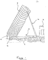
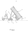
- FIGS 1 and 2 show a tipper truck 1, sometimes referred to as a dump truck, comprising a tractor 2 and a trailer 4.
- the trailer 4 has a trailer chassis or frame 6, and a tipper body 8 is pivotably mounted thereto.
- the tipper body 8 is pivotably mounted to the chassis 6 about a transverse axis 10 that is located at the rear of the chassis 6.
- the tipper body 8 is in the form of a cuboidal container having an open top.
- the rear panel (or door) 12 of the tipper body 8 is hinged at its upper edge and can be locked and unlocked such that it can be opened to allow the contents of the tipper body 8 to be emptied.
- a hydraulic cylinder 14 is provided that is pivotably attached at a lower end to the front of the chassis 6 and pivotably attached an upper end to the front of the tipper body 8.
- the hydraulic cylinder 14 can be extended (as in Figure 1 ) to pivot the tipper body 8 about the axis 10 to a fully tipped position in which, with the rear panel 12 unlocked, any load within the tipper body 8 is emptied onto the ground.
- the tipper body 8 can be lowered back to the resting position under its own weight, thereby causing the cylinder 14 to retract.
- the tipper truck 1 further comprises a hydraulic actuation system 20 for actuating the hydraulic cylinder 14.
- the hydraulic actuation system 20 comprises an oil tank 22, a pump 24 and a valve assembly 26 that are connected with fluid lines to form a fluid circuit.
- a pilot system (not shown) is also provided for switching the valve assembly 26 between various configurations.
- the valve assembly 26 is provided with a port that is hydraulically connected to the hydraulic cylinder 14 with a fluid line 28.
- the valve assembly 26 can be switched between a number of configurations in order to operate the hydraulic cylinder 14. In a bypass configuration of the valve assembly 26, with the pump 24 running, hydraulic fluid is circulated by the pump 24 from the tank 22, through the valve assembly 26 back to the tank 22.
- valve assembly 26 In order to extend the hydraulic cylinder 14 to pivot the tipper body 8 to a fully tipped position (as in Figures 1 and 2 ), the valve assembly 26 is switched to a raising configuration in which the pump 24 pumps hydraulic fluid from the tank 22 into the hydraulic cylinder 14, thus causing it to extend.
- the valve assembly 26 When the hydraulic cylinder 14 has been sufficiently extended (either fully extended or extended by the desired amount), the valve assembly 26 is returned to a bypass configuration in which, with the pump 24 running, hydraulic fluid is circulated from the tank 22 through the valve assembly 26 back to the tank 22. In the bypass configuration of the valve assembly 26 the fluid line 28 is closed and therefore the cylinder 14 remains in the extended configuration.
- the hydraulic actuation system 20 is provided with an automatic knock-off which automatically switches the valve assembly 26 to the bypass configuration when the hydraulic cylinder has been fully extended.
- the automatic knock-off is in the form of a switch which the body of the hydraulic cylinder 14 triggers when it reaches the fully extended position.
- the valve assembly 26 is also provided with a pressure relief bypass valve. If the pressure of the hydraulic fluid in the valve assembly 26 has reached a threshold (which may be due to an excessively heavy load in the tipper body 8) the hydraulic fluid is diverted to the tank 22, rather than being pumped into the hydraulic cylinder 14. This is a safety feature provided to prevent excessively heavy loads from being lifted.
- the pump 24 is shut off and the valve assembly 26 is switched to a lowering configuration. In this configuration, the fluid line 28 is opened and the cylinder 14 retracts under the weight of the tipper body 8 with the hydraulic fluid being returned to the tank 22.
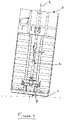
- the chassis 6 may be inclined sideways at an angle ⁇ (i.e. one side of the chassis 6 may be higher than the other side of the chassis 6). If there is a sideways inclination of the chassis 6 then the longitudinal axis A of the hydraulic cylinder 14 will be also be laterally inclined by an angle ⁇ (i.e. the longitudinal axis A of the hydraulic cylinder will have a transverse component).
- the inclination angle ⁇ is defined with reference to vertical.
- the inclination angle could be defined with reference to horizontal (i.e. 90° equates to the cylinder 14 being vertical).
- the tipper truck 1 may topple over sideways, or it may cause the hydraulic cylinder 14 to bend and potentially buckle, which in turn may cause the tipper truck 1 to topple over sideways. Further, if the load within the tipper body 8 is not located laterally centrally then the hydraulic cylinder 14 may bend as it is extended, which may cause the cylinder 14 to buckle and the tipper truck 1 to topple.
- the tipper truck 1 is provided with a lateral condition determining system 40 which can determine whether the lateral condition of the hydraulic cylinder 14 falls outside acceptable limits.
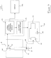
- Figure 4 shows the lateral condition determining system 40 for determining whether the lateral condition of the hydraulic cylinder falls outside acceptable limits based on two lateral states: lateral inclination and lateral bending.
- the lateral condition of the cylinder is a combination of lateral inclination and lateral bending of the cylinder 14.
- the lateral condition may include other factors, or may relate to only one condition (e.g. lateral inclination).
- the lateral condition determining system 40 comprises an inclination (or tilt) sensor 42 for measuring the inclination (i.e. the tilt angle) of the hydraulic cylinder 14 in a plane parallel to the lower pivot axis 30.
- the lower pivot axis 30 of the cylinder 14 is defined by the axis of the eye 32 by which the cylinder 14 is pivotably mounted to the chassis 6.
- the upper pivot axis 34 (which is parallel to the lower axis 30) is defined by the axis of the eye 36 by which the cylinder 14 is pivotably mounted to the tipper body 8.
- the inclination sensor 42 is mounted to the outer surface of the hydraulic cylinder 14 and is positioned such that it can measure the lateral (i.e. sideways) inclination of the hydraulic cylinder 14 in a vertical plane parallel to the pivot axis 30.
- the inclination sensor 42 is arranged to generate an electronic signal which is representative of the inclination angle ⁇ .
- the lateral condition determining system 40 also comprises first and second bending sensors 44, 46 in the form of strain gauges.
- the strain gauges 44, 46 are bonded to the hydraulic cylinder 14 and are located on opposing sides.
- the strain gauges 44, 46 are arranged to generate electronic signals which are representative of the lateral bending force experienced by the hydraulic cylinder 14 in a plane parallel to both the pivot axis 30 and the longitudinal axis of the cylinder 14.
- other bending sensors located in other suitable positions could be used.
- one or more strain gauges could be bounded to the inside of a trunnion pin that passes through the eye 32 to provide a signal representative of bending.
- strain gauges could be bonded to the chassis bracket (not shown) which the trunnion pin passes through to provide a signal representative of bending.
- the lateral condition determining system 40 further comprises a lateral condition determining module 50, a cylinder control module 52 and a display 54.
- the inclination sensor 42 and the first and second bending sensors 44, 46 are connected to the lateral condition determining module 50 by appropriate cabling such that the lateral condition determining module 50 can obtain the signals generated by the sensors 42, 44, 46. It should be appreciated that in other embodiments the sensors 42, 44, 46 could be wirelessly connected to the lateral condition determining module 50.
- the lateral condition determining module 50 is configured to monitor the signals received from the inclination sensor 42 and the two bending sensors 44, 46, and based on these signals, determine whether the lateral condition of the hydraulic cylinder 14 is outside of acceptable limits (i.e.
- the cylinder control module 52 is coupled to the hydraulic actuation system 20 of the tipper truck 1 (via the pilot system) so that it can automatically prevent the hydraulic cylinder 14 from being extended if it is determined that the lateral condition of the hydraulic cylinder 14 is unacceptable.
- the cylinder control module 52 is also capable of automatically actuating the hydraulic cylinder 14 to halt (or stop) the movement of the tipper body 8 if is determined that the lateral condition of the hydraulic cylinder 14 is unacceptable.
- the cylinder control module 52 may be arranged to automatically actuate the hydraulic cylinder 14 to return the tipper body 8 to the resting position if it is determined that the lateral condition of the hydraulic cylinder 14 is unacceptable.
- the cylinder control module 52 may be connected either wired or wirelessly to the hydraulic actuation system 20 to control the pump 24 and/or the valve assembly 26 via the pilot system.
- the display 54 is connected to the lateral condition determining module 50 and is configured to display an alert if the lateral condition determining module 50 determines that the lateral condition of the hydraulic cylinder 14 is unacceptable.
- the display 54 is an LCD screen configured to display a visual alert, and a sounder is also provided to generate an audible alert.
- the display 54 is installed in the dashboard of the tractor 2 such that it is easily visible by an operator. However, in other embodiments it could be located externally, or it could be in the form of a wireless hand-held device (e.g. a smartphone or a tablet). If the display 54 is provided by a portable wireless device, such as a smartphone or tablet, it could also incorporate the lateral condition determining module 50 and the cylinder control module 52 and could communicate wirelessly with the sensors 42, 44, 46. It should be appreciated that other displays, such as an LED could be used to provide a warning.
- the tipper body 8 containing a load 16 (such as sand) is in a resting position ( Figure 5 ). In the resting position of the tipper body 8 it rests on the chassis 6 of the trailer 4 such that the load is transferred directly to the chassis 6.
- a control lever (not shown) of the hydraulic actuation system 20 to extend the hydraulic cylinder 14.
- the lateral condition determining system 40 continuously monitors the signals received from the inclination sensor 42 and the bending sensors 44, 46 to determine if the lateral condition of the hydraulic cylinder 14 is within acceptable limits.
- the lateral condition determining module 50 continuously monitors the value of the inclination signal generated by the inclination sensor 42 (lateral inclination parameter) and the values of the bending signals generated by the first and second bending sensors 44, 46 (lateral bending parameter).
- the value of the inclination signal relates to the lateral (sideways) inclination angle ⁇ of the hydraulic cylinder 14, whilst the value of the bending signals can be converted to a lateral bending moment experienced by the hydraulic cylinder 14. These values could be displayed on the display 56, but this is not essential.
- the lateral condition determining module 50 analyses the inclination signal and the bending signals and utilises an algorithm to determine whether the lateral condition of the hydraulic cylinder 14 is within or outside acceptable limits.
- this is done by the lateral condition determining module 50 determining (a) whether the lateral inclination angle ⁇ of the cylinder 14 is at or above a threshold (i.e. is the angle excessive), or (b) whether the lateral bending of the cylinder is at or above a threshold (i.e. is the bending excessive). If either of these thresholds are exceeded (i.e. if either the angle or the bending is excessive), then the lateral condition determining module 50 determines that the lateral condition of the hydraulic cylinder 14 is unacceptable (i.e. it is outside of acceptable limits). In response to this determination, the lateral condition determining module 50 communicates to the cylinder control module 52 which prevents the hydraulic cylinder 14 from being extended.
- the display 54 generates a visual alert and an audible sound which indicates to the operator that the lateral condition of the cylinder 14 is outside of acceptable limits. This prevents the operator from extending the hydraulic cylinder 14, which could otherwise cause the tipper 1 to topple over and/or the cylinder 14 to buckle. Further, in response to the visual warning the operator can drive the tipper 1 to a more appropriate location where the ground is more level.
- the lateral condition determining system 40 continuously monitors the signals generated by the sensors 42, 44, 46 and the lateral condition determining module 50 continuously assesses whether the lateral condition of the hydraulic cylinder 14 is outside acceptable limits. Specifically, even after a tipping operation has been commenced (i.e. when the tipper body 8 is pivoted away from the resting position), the lateral condition determining module 50 checks to ascertain whether the lateral inclination angle ⁇ is excessive, or if the lateral bending is excessive. If it is ascertained that either of these parameters are outside acceptable limits, the cylinder control module 52 automatically halts (stops) the tipping operation and the hydraulic cylinder 14 is retracted to lower the tipper body 8 to the resting position. The display 54 also generates a visual and an audible alert. Again, this prevents the hydraulic cylinder 14 from buckling and/or the tipper 1 from toppling, providing a major safety benefit.
- FIG. 7 shows an example of a lateral condition determining system 140 which is similar to the first embodiment.
- an inclination sensor 48 is provided which is mounted to the tipper body 8.
- the inclination sensor 48 is arranged such that it can measure the lateral inclination (i.e. side-to-side inclination) of the tipper body 8.
- the output of the inclination sensor 48 depends on both the lateral inclination and the lateral bending of the hydraulic cylinder 14. Therefore, the output of the inclination sensor 48 generates a signal relating to the lateral state of the hydraulic cylinder.
- the lateral condition determining module 150 receives the output of the inclination sensor 48 and determines whether the lateral condition of the hydraulic cylinder 14 (and thus the tipper body 8 itself) is outside acceptable limits. If it is determined that the lateral condition of the cylinder 14 is outside acceptable limits then a warning may be displayed on the display 154 and tipping may be halted or the cylinder lowered using the cylinder control module 152. Providing an inclination sensor 48 on the tipper body 8 may be advantageous in that a single sensor can be used to provide an indication of cylinder inclination and bending.
- the tipping operation is stopped (i.e. movement of the tipper body 8 is halted), the tipper body 8 is returned to a resting position, and an alert is generated.
- the tipper body 8 is stopped, and the operator may need to manually lower the tipper body.
- the lateral condition determining module 50 determines that the lateral condition of the hydraulic cylinder 14 is outside acceptable limits if the lateral inclination is above a threshold or the lateral bending is above a threshold.
- the lateral condition determining module 50 could determine that the lateral condition of the hydraulic cylinder 14 is unacceptable only if the inclination and the bending exceed thresholds.
- the lateral condition of the hydraulic cylinder 14 could be determined as unacceptable based on a combination of the inclination and the bending being excessive (i.e. individually the inclination and bending are acceptable but in combination they present a risk).
- the system 40 could be configured to model the hydraulic cylinder 14 and/or the tipper truck 1 based on the signals received.
- the inclination sensor 42 generates a signal representative of the lateral inclination of the hydraulic cylinder 14 by using an inclination sensor mounted to the cylinder 14.
- the lateral inclination of the hydraulic cylinder 14 could be monitored by using an inclination sensor mounted to the chassis 6 of the tipper measuring the sideways inclination ⁇ .
- any suitable sensors positioned in any appropriate location could be used to generate a signal indicative of or related to the lateral inclination of the hydraulic cylinder 14.
- there are two bending sensors 44, 46 it should be appreciated that any suitable number of sensors could be used. For example, for a telescoping cylinder, one or more bending sensors could be attached to each stage of the cylinder.
- the lateral condition determining module 50 monitors both the lateral inclination and the lateral bending of the hydraulic cylinder 14. However, it should be appreciated that the module 50 may monitor only one of these conditions (e.g. only inclination or only bending). In other embodiments, the module 50 may monitor other conditions as well.
- a position sensor is provided to generate an angular positional parameter relating to the angular position (i.e. tip angle) of the tipper body 8.
- This could be in the form of an inclination sensor attached to the hydraulic cylinder 14 and capable of generating a fore-aft inclination parameter relating to the fore-aft inclination of the hydraulic cylinder (i.e. the inclination in a plane perpendicular to the pivot axes 30, 34 of the cylinder 14). Due to the fixed relationship between the inclination angle of the cylinder 14 and the tip angle of the tipper body 8 the output of the inclination sensor relates to the tip angle of the tipper body 8.
- the lateral condition determining module 50 would also monitor the angular positional parameter relating to the tip angle of the tipper body 8 and would determine whether the lateral condition of the cylinder is outside acceptable limits based on the lateral state parameters (e.g. lateral inclination parameter and/or lateral bending parameter), and the angular position parameter. For example, it may be possible to tolerate greater lateral bending/inclination at lower tip angles, whereas at a large tip angle (e.g. 50°) the lateral bending/inclination may have to be lower for the lateral condition of the cylinder to be within acceptable limits. In other words, for the same lateral bending/inclination the lateral determining module may determine that the lateral condition is excessive when at a high tip angle, but acceptable at a low tip angle.
- the lateral state parameters e.g. lateral inclination parameter and/or lateral bending parameter
- the lateral determining module may determine that the lateral condition is excessive when at a high tip angle, but acceptable at a low tip angle.
- the angular positional parameter is generated by an inclination sensor attached to the hydraulic cylinder 14.
- an inclination sensor could be attached to the tipper body 8 to measure the angular position of the tipper body.
- a rotary position sensor could be used to measure the amount of rotation at either the pivot axis 10 of the tipper body 8, or the lower or upper pivot axes 30, 34 of the hydraulic cylinder 14.
- the signals generated by these sensors can all be related to the angular position of the tipper body (either with respect to the chassis 6 or horizontal).
- a linear position sensor could be used to monitor the length of the hydraulic cylinder 14.
- Such a sensor could include a Hall effect sensor, for example.
- the signal generated by the linear position sensor could again be used to determine the angular position of the tipper body 8.
- a distance sensor could be provided to measure the vertical distance between the frame and the lower front edge (i.e. the raised edge) of the tipper body 8. Such a sensor would generate an angular positional parameter as the output of the sensor relates to the angular position of the tipper body 8.
- a pressure sensor is provided to generate a pressure parameter relating to the pressure of the hydraulic fluid within the hydraulic cylinder 14.
- the lateral condition determining module 50 would also monitor the pressure parameter relating to hydraulic pressure within the hydraulic cylinder 14 (which relates to the load within the tipper body) and would determine whether the lateral condition of the cylinder is outside acceptable limits based on the lateral state parameters (e.g. lateral inclination parameter and/or lateral bending parameter), and the pressure parameter. For example, it may be possible to tolerate greater lateral bending/inclination at lower pressures (i.e. lower loads), whereas at a high pressure parameter (i.e.
- the lateral bending/inclination may have to be lower for the lateral condition of the cylinder to be within acceptable limits.
- the lateral determining module may determine that the lateral condition is excessive when at a high pressure parameter (high load), but acceptable at a low pressure parameter (low load).
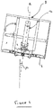
- the system could be used with any suitable type of tipper truck in which a tipper body 8 can be pivoted or moved by a hydraulic cylinder.
- the tipper truck 1 may comprises a tractor 2 having a frame 6 with a hydraulic cylinder 14 connected between the frame 6 and the tipper body 8.
- the tipper truck 14 further comprises a drawbar 11 that is pivotably connected at a first end to the frame 6 at a first pivot axis 10 and at a second end to the tipper body 8 at a second pivot axis 11.
- the hydraulic cylinder 14 In order to pivot the tipper body 8 from a resting position (not shown) to the fully tipped position ( Figure 8 ), the hydraulic cylinder 14 is extended which causes the tipper body 8 to pivot clockwise (in Figure 8 ) with respect to the frame 6 about the pivot axis 10, and with respect to the drawbar 9 about the pivot axis 11. It should also be appreciated that in order to measure the angular position (i.e. tip angle) of the tipper body 8 the inclination angle of the drawbar 9 could be measured since there is a fixed relationship between this angle and the tip angle (and the inclination angle of the hydraulic cylinder 14).
- the lateral condition determining system 40 may be one of many intelligent systems that the tipper truck 1 is provided with and could therefore be combined with any suitable system for providing information regarding the tipper vehicle and/or the load carried by the tipper body. If multiple intelligent systems are provided, they may share the same display or processors, for example.
- Some aspects of the above-described apparatus, system and methods may be embodied as machine readable instructions such as processor control code, for example on a non-volatile carrier medium such as a disk, CD- or DVD-ROM, programmed memory such as read only memory (Firmware), or on a data carrier such as an optical or electrical signal carrier.
- processor control code for example on a non-volatile carrier medium such as a disk, CD- or DVD-ROM, programmed memory such as read only memory (Firmware), or on a data carrier such as an optical or electrical signal carrier.
- a DSP Digital Signal Processor
- ASIC Application Specific Integrated Circuit
- FPGA Field Programmable Gate Array
- the code may comprise conventional program code or microcode or, for example code for setting up or controlling an ASIC or FPGA.
- the code may also comprise code for dynamically configuring re-configurable apparatus such as re-programmable logic gate arrays.
- the code may comprise code for a hardware description language such as Verilog TM or VHDL (Very high speed integrated circuit Hardware Description Language).
- the code may be distributed between a plurality of coupled components in communication with one another.
- embodiments may also be implemented using code running on a field-(re)programmable analogue array or similar device in order to configure analogue hardware.
Landscapes
- Engineering & Computer Science (AREA)
- Mechanical Engineering (AREA)
- Transportation (AREA)
- Physics & Mathematics (AREA)
- Fluid Mechanics (AREA)
- General Engineering & Computer Science (AREA)
- Component Parts Of Construction Machinery (AREA)
- Vehicle Body Suspensions (AREA)
- Manipulator (AREA)
Claims (13)
- Verfahren zum Betreiben eines Kippers (1), der einen Kipperkörper (8) umfasst, der in Bezug auf einen Rahmen (6) mit einem Hydraulikzylinder (14) schwenkbar beweglich ist, der dazwischen angeordnet und betätigungsfähig ist, um den Kipperkörper zu schwenken, dadurch gekennzeichnet, dass das Verfahren umfasst:Empfangen eines Seitenabwinkelungsparameters, der ein seitliches Abwinkeln des Hydraulikzylinders betrifft;Ermitteln auf der Grundlage zumindest des Seitenabwinkelungsparameters, ob sich der Seitenzustand des Hydraulikzylinders außerhalb zulässiger Grenzwerte befindet; undErzeugen einer Ausgabe, wenn festgestellt wird, dass sich der Seitenzustand des Hydraulikzylinders außerhalb zulässiger Grenzwerte befindet.
- Verfahren nach Anspruch 1, wobei ein Seitenneigungsparameter empfangen wird, der die Seitenneigung des Hydraulikzylinders betrifft, und wobei auf der Grundlage zumindest des Seitenneigungsparameters ermittelt wird, ob sich der Seitenzustand des Hydraulikzylinders außerhalb zulässiger Grenzwerte befindet.
- Verfahren nach Anspruch 2, wobei der Seitenneigungsparameter durch einen Neigungssensor (42, 48) erzeugt wird, der angeordnet ist, um die Seitenneigung des Hydraulikzylinders oder des Kipperkörpers zu messen.
- Verfahren nach Anspruch 3, wobei der Neigungssensor (42, 48) am Hydraulikzylinder oder am Kipperkörper montiert ist.
- Verfahren nach einem vorhergehenden Anspruch, ferner umfassend ein Empfangen eines Winkelpositionsparameters, der den Kippwinkel des Kipperkörpers betrifft, wobei auf der Grundlage des mindestens einen Seitenabwinkelungsparameters und des Winkelpositionsparameters ermittelt wird, ob sich der Seitenzustand des Hydraulikzylinders außerhalb zulässiger Grenzwerte befindet.
- Verfahren nach einem vorhergehenden Anspruch, ferner umfassend ein Empfangen eines Druckparameters, der den Hydraulikdruck innerhalb des Hydraulikzylinders betrifft, wobei auf der Grundlage des mindestens einen Seitenabwinkelungsparameters und des Druckparameters ermittelt wird, ob sich der Seitenzustand des Hydraulikzylinders außerhalb zulässiger Grenzwerte befindet.
- Verfahren nach einem vorhergehenden Anspruch, ferner umfassend ein Erzeugen einer Warnung wie zum Beispiel einer optischen und/oder einer akustischen Warnung, wenn festgestellt wird, dass sich der Seitenzustand des Hydraulikzylinders außerhalb zulässiger Grenzwerte befindet.
- System (40, 140) für einen Kipper (1), der einen Kipperkörper (8) umfasst, der in Bezug auf einen Rahmen (6) mit einem Hydraulikzylinder (14) schwenkbar beweglich ist, der dazwischen angeordnet und betätigungsfähig ist, um den Kipperkörper zu schwenken, dadurch gekennzeichnet, dass das System umfasst:
ein Seitenzustand-Ermittlungsmodul (50), das angeordnet ist, um:einen Seitenabwinkelungsparameter zu empfangen, der ein seitliches Abwinkeln des Hydraulikzylinders betrifft;auf der Grundlage zumindest des Seitenabwinkelungsparameters zu ermitteln, ob sich der Seitenzustand des Hydraulikzylinders außerhalb zulässiger Grenzwerte befindet; undeine Ausgabe zu erzeugen, wenn festgestellt wird, dass sich der Seitenzustand des Hydraulikzylinders außerhalb zulässiger Grenzwerte befindet. - System nach Anspruch 8, wobei das Seitenzustand-Ermittlungsmodul angeordnet ist, um:einen Seitenneigungsparameter zu empfangen, der die Seitenneigung des Hydraulikzylinders betrifft, undauf der Grundlage zumindest des Seitenneigungsparameters zu ermitteln, ob sich der Seitenzustand des Hydraulikzylinders außerhalb zulässiger Grenzwerte befindet.
- System nach Anspruch 8, wobei das Seitenzustand-Ermittlungsmodul angeordnet ist, um:einen Winkelpositionsparameter zu empfangen, der den Kippwinkel des Kipperkörpers betrifft; undauf der Grundlage des Seitenabwinkelungsparameters und des Winkelpositionsparameters zu ermitteln, ob sich der Seitenzustand des Hydraulikzylinders außerhalb zulässiger Grenzwerte befindet.
- System nach einem der Ansprüche 8 bis 10, wobei das Seitenzustand-Ermittlungsmodul angeordnet ist, um:einen Druckparameter zu empfangen, der den Hydraulikdruck innerhalb des Hydraulikzylinders betrifft; undauf der Grundlage des Seitenabwinkelungsparameters und des Druckparameters zu ermitteln, ob sich der Seitenzustand des Hydraulikzylinders außerhalb zulässiger Grenzwerte befindet.
- System nach einem der Ansprüche 8 bis 11, ferner umfassend einen Warnungsgenerator wie zum Beispiel einen Generator für optische und/oder akustische Warnungen, der angeordnet ist, um eine Warnung zu erzeugen, wenn festgestellt wird, dass sich der Seitenzustand des Hydraulikzylinders außerhalb zulässiger Grenzwerte befindet.
- Kipper (1), umfassend:einen Kipperkörper (8), der in Bezug auf einen Rahmen (6) schwenkbar beweglich ist;eine Hydraulikzylinder (14), der zwischen dem Rahmen und dem Kipperkörper angeordnet und betätigungsfähig ist, um den Kipperkörper zu schwenken; undein System (40, 140) nach einem der Ansprüche 8 bis 12.
Priority Applications (1)
| Application Number | Priority Date | Filing Date | Title |
|---|---|---|---|
| PL16157742T PL3064397T3 (pl) | 2015-03-06 | 2016-02-26 | Sposób i system obsługi wywrotki |
Applications Claiming Priority (1)
| Application Number | Priority Date | Filing Date | Title |
|---|---|---|---|
| GB1503871.4A GB2536066A (en) | 2015-03-06 | 2015-03-06 | Method and system for operating a tipper |
Publications (2)
| Publication Number | Publication Date |
|---|---|
| EP3064397A1 EP3064397A1 (de) | 2016-09-07 |
| EP3064397B1 true EP3064397B1 (de) | 2020-02-19 |
Family
ID=52998549
Family Applications (1)
| Application Number | Title | Priority Date | Filing Date |
|---|---|---|---|
| EP16157742.4A Active EP3064397B1 (de) | 2015-03-06 | 2016-02-26 | Verfahren und system zum betreiben eines kippers |
Country Status (6)
| Country | Link |
|---|---|
| US (1) | US10076989B2 (de) |
| EP (1) | EP3064397B1 (de) |
| CN (3) | CN205930428U (de) |
| BR (1) | BR102016004883B1 (de) |
| GB (2) | GB2536066A (de) |
| PL (1) | PL3064397T3 (de) |
Cited By (1)
| Publication number | Priority date | Publication date | Assignee | Title |
|---|---|---|---|---|
| EP4635758A1 (de) * | 2024-04-19 | 2025-10-22 | Volvo Truck Corporation | Verfahren und system zur kippvermeidung eines fahrzeuggespanns mit einem traktor und einem kippanhänger |
Families Citing this family (13)
| Publication number | Priority date | Publication date | Assignee | Title |
|---|---|---|---|---|
| GB201503874D0 (en) * | 2015-03-06 | 2015-04-22 | Hyva Holding Bv | Method and system for operating a tipper vehicle |
| GB2536066A (en) * | 2015-03-06 | 2016-09-07 | Hyva Holding Bv | Method and system for operating a tipper |
| EP3437925B1 (de) * | 2016-03-30 | 2021-01-27 | Hitachi Construction Machinery Co., Ltd. | Transportfahrzeug |
| GB2553377A (en) * | 2016-09-06 | 2018-03-07 | Hyva Holding Bv | Method and system for operating a tipper |
| JP6612210B2 (ja) * | 2016-12-26 | 2019-11-27 | 本田技研工業株式会社 | 作業機 |
| US10800310B2 (en) * | 2017-06-21 | 2020-10-13 | Columbia Trailer Co. Inc. | Trailer tipper featuring multi-use tilt sensors for automating leveling and tipping operations |
| CN109615726B (zh) * | 2018-12-12 | 2022-01-14 | 湖北汽车工业学院 | 信息输出方法、装置、自卸车系统、计算机及存储介质 |
| CA3125447A1 (en) * | 2018-12-31 | 2020-07-09 | Antitip, Llc | Tip-over prevention for dumping vehicles |
| WO2020219237A1 (en) * | 2019-04-24 | 2020-10-29 | Command Alkon Incorporated | Method and system for confirming delivery of bulk material from a bed of a dump truck |
| CN110254323A (zh) * | 2019-06-27 | 2019-09-20 | 袁菊花 | 自卸车的举升装置 |
| US10988067B1 (en) | 2020-10-26 | 2021-04-27 | Veradyn Llc | Dump trailer and system for a semi-trailer truck |
| US12409768B2 (en) | 2020-10-26 | 2025-09-09 | Veradyn Llc | Dump trailer and system for a semi-trailer truck |
| EP4365023B1 (de) * | 2022-11-07 | 2025-09-17 | Hiab AB | Arbeitsausrüstung mit fähigkeit zur verhinderung des knickens eines hydraulikzylinders |
Family Cites Families (21)
| Publication number | Priority date | Publication date | Assignee | Title |
|---|---|---|---|---|
| FR1287213A (fr) * | 1961-04-26 | 1962-03-09 | C H Johnson Machinery Ltd | Véhicule à benne basculante |
| US3640578A (en) * | 1970-02-06 | 1972-02-08 | James Harold Finney | Levelling system for semi end dump trucks |
| US3921128A (en) * | 1974-05-28 | 1975-11-18 | Edwin Des Snead | Truck roll warning system |
| US4216996A (en) * | 1978-11-20 | 1980-08-12 | Pitts Charlie C | Stabilizer for dumping vehicles |
| GB2046957A (en) * | 1979-03-21 | 1980-11-19 | Edbro Holdings | Vehicle stability control system |
| GB2169565A (en) * | 1984-11-23 | 1986-07-16 | Scapa Engineering Limited | Attitude control means for tipping apparatus or for the load support structure of a tipping vehicle |
| US4682145A (en) * | 1985-05-03 | 1987-07-21 | Brawner Jr Clarence A | Truck level sensing and indicating system |
| GB8524610D0 (en) * | 1985-10-05 | 1985-11-06 | Monkhouse B A | Commercial vehicle load indicating device |
| US4988974A (en) * | 1989-07-17 | 1991-01-29 | Fury Tommy J | Warning and safety system indicating truck trailer tip-over condition |
| US5742228A (en) * | 1993-12-24 | 1998-04-21 | Litan Advanced Instrumentation Ltd. | System for preventing tipper truck overturning |
| AR024080A1 (es) * | 1999-05-25 | 2002-09-04 | Ostermeyer Bernd | Una disposicion de volquete para vehiculos y un vehiculo con volquete que la utiliza |
| CN2705361Y (zh) * | 2003-12-05 | 2005-06-22 | 王成东 | 设有自卸装置的手推车及其控制系统 |
| JP4933478B2 (ja) * | 2008-04-24 | 2012-05-16 | 日立建機株式会社 | 運搬車両 |
| AU2009100034A4 (en) * | 2009-01-21 | 2009-02-26 | Nijhuis, Johannes | Tip Safe |
| US8231178B2 (en) * | 2010-02-16 | 2012-07-31 | Les Placements Marcel Bibeau Inc. | Mobile base for reducing lateral pressure of the body lift cylinder of a dump body |
| DE102010002701A1 (de) * | 2010-03-09 | 2011-09-15 | Franz Xaver Meiller Fahrzeug- Und Maschinenfabrik - Gmbh & Co Kg | Kippzustandsüberwachung |
| US8833861B2 (en) * | 2010-12-03 | 2014-09-16 | Caterpillar Inc. | Loading analysis system and method |
| GB2497134B8 (en) * | 2011-12-02 | 2014-07-23 | Caterpiller Sarl | Determing the relative orientation of members of an articulated work machine |
| JP5746802B2 (ja) * | 2012-02-22 | 2015-07-08 | 日立建機株式会社 | 運搬車両 |
| DE102013202415A1 (de) * | 2013-02-14 | 2014-08-14 | Franz Xaver Meiller Fahrzeug- Und Maschinenfabrik - Gmbh & Co Kg | Kipperfahrzeug |
| GB2536066A (en) * | 2015-03-06 | 2016-09-07 | Hyva Holding Bv | Method and system for operating a tipper |
-
2015
- 2015-03-06 GB GB1503871.4A patent/GB2536066A/en not_active Withdrawn
- 2015-12-31 CN CN201521145520.8U patent/CN205930428U/zh not_active Expired - Lifetime
- 2015-12-31 CN CN201511036180.XA patent/CN105936233B/zh active Active
- 2015-12-31 CN CN201720021057.9U patent/CN206589757U/zh not_active Expired - Lifetime
-
2016
- 2016-02-26 GB GBGB1603356.5A patent/GB201603356D0/en not_active Ceased
- 2016-02-26 EP EP16157742.4A patent/EP3064397B1/de active Active
- 2016-02-26 PL PL16157742T patent/PL3064397T3/pl unknown
- 2016-03-04 US US15/061,495 patent/US10076989B2/en active Active
- 2016-03-04 BR BR102016004883-4A patent/BR102016004883B1/pt active IP Right Grant
Non-Patent Citations (1)
| Title |
|---|
| None * |
Cited By (1)
| Publication number | Priority date | Publication date | Assignee | Title |
|---|---|---|---|---|
| EP4635758A1 (de) * | 2024-04-19 | 2025-10-22 | Volvo Truck Corporation | Verfahren und system zur kippvermeidung eines fahrzeuggespanns mit einem traktor und einem kippanhänger |
Also Published As
| Publication number | Publication date |
|---|---|
| BR102016004883B1 (pt) | 2022-10-25 |
| GB201503871D0 (en) | 2015-04-22 |
| GB2536066A (en) | 2016-09-07 |
| PL3064397T3 (pl) | 2020-09-21 |
| GB201603356D0 (en) | 2016-04-13 |
| EP3064397A1 (de) | 2016-09-07 |
| CN105936233A (zh) | 2016-09-14 |
| CN105936233B (zh) | 2024-04-09 |
| US10076989B2 (en) | 2018-09-18 |
| CN206589757U (zh) | 2017-10-27 |
| US20170021751A1 (en) | 2017-01-26 |
| CN205930428U (zh) | 2017-02-08 |
| BR102016004883A2 (pt) | 2016-10-25 |
Similar Documents
| Publication | Publication Date | Title |
|---|---|---|
| EP3064397B1 (de) | Verfahren und system zum betreiben eines kippers | |
| EP3064398B1 (de) | Verfahren und system zum betreiben eines kippers | |
| EP3290265B1 (de) | Verfahren und system zum betreiben eines kippers | |
| EP3822117B1 (de) | Verfahren und system zum betreiben eines kippers | |
| EP3265341B1 (de) | Verfahren und vorrichtung zur bestimmung der masse einer last in einem kipperkörper | |
| US8965637B2 (en) | Method of operating a working machine | |
| AU2010214533A1 (en) | Transporter vehicle | |
| GB2537590A (en) | Method and system for determining a residual load | |
| EP3266001B1 (de) | Verfahren und system zur erzeugung eines dienstindikators | |
| CN205706328U (zh) | 空本体确定系统、自卸车、自卸式车辆和液压缸组件 | |
| KR102592203B1 (ko) | 덤프트럭의 데크 제어장치 및 제어방법 | |
| CN205468888U (zh) | 用于操作自卸车的系统、自卸车、自卸式车辆和液压缸组件 |
Legal Events
| Date | Code | Title | Description |
|---|---|---|---|
| PUAI | Public reference made under article 153(3) epc to a published international application that has entered the european phase |
Free format text: ORIGINAL CODE: 0009012 |
|
| AK | Designated contracting states |
Kind code of ref document: A1 Designated state(s): AL AT BE BG CH CY CZ DE DK EE ES FI FR GB GR HR HU IE IS IT LI LT LU LV MC MK MT NL NO PL PT RO RS SE SI SK SM TR |
|
| AX | Request for extension of the european patent |
Extension state: BA ME |
|
| STAA | Information on the status of an ep patent application or granted ep patent |
Free format text: STATUS: REQUEST FOR EXAMINATION WAS MADE |
|
| 17P | Request for examination filed |
Effective date: 20170307 |
|
| RBV | Designated contracting states (corrected) |
Designated state(s): AL AT BE BG CH CY CZ DE DK EE ES FI FR GB GR HR HU IE IS IT LI LT LU LV MC MK MT NL NO PL PT RO RS SE SI SK SM TR |
|
| STAA | Information on the status of an ep patent application or granted ep patent |
Free format text: STATUS: EXAMINATION IS IN PROGRESS |
|
| 17Q | First examination report despatched |
Effective date: 20181214 |
|
| GRAP | Despatch of communication of intention to grant a patent |
Free format text: ORIGINAL CODE: EPIDOSNIGR1 |
|
| STAA | Information on the status of an ep patent application or granted ep patent |
Free format text: STATUS: GRANT OF PATENT IS INTENDED |
|
| INTG | Intention to grant announced |
Effective date: 20190829 |
|
| GRAS | Grant fee paid |
Free format text: ORIGINAL CODE: EPIDOSNIGR3 |
|
| GRAA | (expected) grant |
Free format text: ORIGINAL CODE: 0009210 |
|
| STAA | Information on the status of an ep patent application or granted ep patent |
Free format text: STATUS: THE PATENT HAS BEEN GRANTED |
|
| AK | Designated contracting states |
Kind code of ref document: B1 Designated state(s): AL AT BE BG CH CY CZ DE DK EE ES FI FR GB GR HR HU IE IS IT LI LT LU LV MC MK MT NL NO PL PT RO RS SE SI SK SM TR |
|
| REG | Reference to a national code |
Ref country code: CH Ref legal event code: EP |
|
| REG | Reference to a national code |
Ref country code: DE Ref legal event code: R096 Ref document number: 602016029893 Country of ref document: DE |
|
| REG | Reference to a national code |
Ref country code: AT Ref legal event code: REF Ref document number: 1234577 Country of ref document: AT Kind code of ref document: T Effective date: 20200315 |
|
| REG | Reference to a national code |
Ref country code: IE Ref legal event code: FG4D |
|
| REG | Reference to a national code |
Ref country code: SE Ref legal event code: TRGR |
|
| REG | Reference to a national code |
Ref country code: NL Ref legal event code: MP Effective date: 20200219 |
|
| PG25 | Lapsed in a contracting state [announced via postgrant information from national office to epo] |
Ref country code: RS Free format text: LAPSE BECAUSE OF FAILURE TO SUBMIT A TRANSLATION OF THE DESCRIPTION OR TO PAY THE FEE WITHIN THE PRESCRIBED TIME-LIMIT Effective date: 20200219 Ref country code: NO Free format text: LAPSE BECAUSE OF FAILURE TO SUBMIT A TRANSLATION OF THE DESCRIPTION OR TO PAY THE FEE WITHIN THE PRESCRIBED TIME-LIMIT Effective date: 20200519 Ref country code: FI Free format text: LAPSE BECAUSE OF FAILURE TO SUBMIT A TRANSLATION OF THE DESCRIPTION OR TO PAY THE FEE WITHIN THE PRESCRIBED TIME-LIMIT Effective date: 20200219 |
|
| REG | Reference to a national code |
Ref country code: LT Ref legal event code: MG4D |
|
| PG25 | Lapsed in a contracting state [announced via postgrant information from national office to epo] |
Ref country code: HR Free format text: LAPSE BECAUSE OF FAILURE TO SUBMIT A TRANSLATION OF THE DESCRIPTION OR TO PAY THE FEE WITHIN THE PRESCRIBED TIME-LIMIT Effective date: 20200219 Ref country code: GR Free format text: LAPSE BECAUSE OF FAILURE TO SUBMIT A TRANSLATION OF THE DESCRIPTION OR TO PAY THE FEE WITHIN THE PRESCRIBED TIME-LIMIT Effective date: 20200520 Ref country code: BG Free format text: LAPSE BECAUSE OF FAILURE TO SUBMIT A TRANSLATION OF THE DESCRIPTION OR TO PAY THE FEE WITHIN THE PRESCRIBED TIME-LIMIT Effective date: 20200519 Ref country code: IS Free format text: LAPSE BECAUSE OF FAILURE TO SUBMIT A TRANSLATION OF THE DESCRIPTION OR TO PAY THE FEE WITHIN THE PRESCRIBED TIME-LIMIT Effective date: 20200619 Ref country code: LV Free format text: LAPSE BECAUSE OF FAILURE TO SUBMIT A TRANSLATION OF THE DESCRIPTION OR TO PAY THE FEE WITHIN THE PRESCRIBED TIME-LIMIT Effective date: 20200219 |
|
| PG25 | Lapsed in a contracting state [announced via postgrant information from national office to epo] |
Ref country code: NL Free format text: LAPSE BECAUSE OF FAILURE TO SUBMIT A TRANSLATION OF THE DESCRIPTION OR TO PAY THE FEE WITHIN THE PRESCRIBED TIME-LIMIT Effective date: 20200219 |
|
| REG | Reference to a national code |
Ref country code: CH Ref legal event code: PL |
|
| REG | Reference to a national code |
Ref country code: BE Ref legal event code: MM Effective date: 20200229 |
|
| PG25 | Lapsed in a contracting state [announced via postgrant information from national office to epo] |
Ref country code: SK Free format text: LAPSE BECAUSE OF FAILURE TO SUBMIT A TRANSLATION OF THE DESCRIPTION OR TO PAY THE FEE WITHIN THE PRESCRIBED TIME-LIMIT Effective date: 20200219 Ref country code: PT Free format text: LAPSE BECAUSE OF FAILURE TO SUBMIT A TRANSLATION OF THE DESCRIPTION OR TO PAY THE FEE WITHIN THE PRESCRIBED TIME-LIMIT Effective date: 20200712 Ref country code: CZ Free format text: LAPSE BECAUSE OF FAILURE TO SUBMIT A TRANSLATION OF THE DESCRIPTION OR TO PAY THE FEE WITHIN THE PRESCRIBED TIME-LIMIT Effective date: 20200219 Ref country code: RO Free format text: LAPSE BECAUSE OF FAILURE TO SUBMIT A TRANSLATION OF THE DESCRIPTION OR TO PAY THE FEE WITHIN THE PRESCRIBED TIME-LIMIT Effective date: 20200219 Ref country code: EE Free format text: LAPSE BECAUSE OF FAILURE TO SUBMIT A TRANSLATION OF THE DESCRIPTION OR TO PAY THE FEE WITHIN THE PRESCRIBED TIME-LIMIT Effective date: 20200219 Ref country code: DK Free format text: LAPSE BECAUSE OF FAILURE TO SUBMIT A TRANSLATION OF THE DESCRIPTION OR TO PAY THE FEE WITHIN THE PRESCRIBED TIME-LIMIT Effective date: 20200219 Ref country code: SM Free format text: LAPSE BECAUSE OF FAILURE TO SUBMIT A TRANSLATION OF THE DESCRIPTION OR TO PAY THE FEE WITHIN THE PRESCRIBED TIME-LIMIT Effective date: 20200219 Ref country code: ES Free format text: LAPSE BECAUSE OF FAILURE TO SUBMIT A TRANSLATION OF THE DESCRIPTION OR TO PAY THE FEE WITHIN THE PRESCRIBED TIME-LIMIT Effective date: 20200219 Ref country code: LU Free format text: LAPSE BECAUSE OF NON-PAYMENT OF DUE FEES Effective date: 20200226 Ref country code: LT Free format text: LAPSE BECAUSE OF FAILURE TO SUBMIT A TRANSLATION OF THE DESCRIPTION OR TO PAY THE FEE WITHIN THE PRESCRIBED TIME-LIMIT Effective date: 20200219 |
|
| REG | Reference to a national code |
Ref country code: AT Ref legal event code: MK05 Ref document number: 1234577 Country of ref document: AT Kind code of ref document: T Effective date: 20200219 |
|
| REG | Reference to a national code |
Ref country code: DE Ref legal event code: R097 Ref document number: 602016029893 Country of ref document: DE |
|
| PG25 | Lapsed in a contracting state [announced via postgrant information from national office to epo] |
Ref country code: LI Free format text: LAPSE BECAUSE OF NON-PAYMENT OF DUE FEES Effective date: 20200229 Ref country code: CH Free format text: LAPSE BECAUSE OF NON-PAYMENT OF DUE FEES Effective date: 20200229 Ref country code: MC Free format text: LAPSE BECAUSE OF FAILURE TO SUBMIT A TRANSLATION OF THE DESCRIPTION OR TO PAY THE FEE WITHIN THE PRESCRIBED TIME-LIMIT Effective date: 20200219 |
|
| PLBE | No opposition filed within time limit |
Free format text: ORIGINAL CODE: 0009261 |
|
| STAA | Information on the status of an ep patent application or granted ep patent |
Free format text: STATUS: NO OPPOSITION FILED WITHIN TIME LIMIT |
|
| REG | Reference to a national code |
Ref country code: DE Ref legal event code: R082 Ref document number: 602016029893 Country of ref document: DE Representative=s name: HL KEMPNER PATENTANWAELTE, SOLICITORS (ENGLAND, DE Ref country code: DE Ref legal event code: R082 Ref document number: 602016029893 Country of ref document: DE Representative=s name: HL KEMPNER PATENTANWALT, RECHTSANWALT, SOLICIT, DE Ref country code: DE Ref legal event code: R082 Ref document number: 602016029893 Country of ref document: DE Representative=s name: HL KEMPNER PARTG MBB, DE |
|
| 26N | No opposition filed |
Effective date: 20201120 |
|
| PG25 | Lapsed in a contracting state [announced via postgrant information from national office to epo] |
Ref country code: AT Free format text: LAPSE BECAUSE OF FAILURE TO SUBMIT A TRANSLATION OF THE DESCRIPTION OR TO PAY THE FEE WITHIN THE PRESCRIBED TIME-LIMIT Effective date: 20200219 Ref country code: IE Free format text: LAPSE BECAUSE OF NON-PAYMENT OF DUE FEES Effective date: 20200226 |
|
| PG25 | Lapsed in a contracting state [announced via postgrant information from national office to epo] |
Ref country code: SI Free format text: LAPSE BECAUSE OF FAILURE TO SUBMIT A TRANSLATION OF THE DESCRIPTION OR TO PAY THE FEE WITHIN THE PRESCRIBED TIME-LIMIT Effective date: 20200219 Ref country code: BE Free format text: LAPSE BECAUSE OF NON-PAYMENT OF DUE FEES Effective date: 20200229 |
|
| PG25 | Lapsed in a contracting state [announced via postgrant information from national office to epo] |
Ref country code: TR Free format text: LAPSE BECAUSE OF FAILURE TO SUBMIT A TRANSLATION OF THE DESCRIPTION OR TO PAY THE FEE WITHIN THE PRESCRIBED TIME-LIMIT Effective date: 20200219 Ref country code: MT Free format text: LAPSE BECAUSE OF FAILURE TO SUBMIT A TRANSLATION OF THE DESCRIPTION OR TO PAY THE FEE WITHIN THE PRESCRIBED TIME-LIMIT Effective date: 20200219 Ref country code: CY Free format text: LAPSE BECAUSE OF FAILURE TO SUBMIT A TRANSLATION OF THE DESCRIPTION OR TO PAY THE FEE WITHIN THE PRESCRIBED TIME-LIMIT Effective date: 20200219 |
|
| PG25 | Lapsed in a contracting state [announced via postgrant information from national office to epo] |
Ref country code: MK Free format text: LAPSE BECAUSE OF FAILURE TO SUBMIT A TRANSLATION OF THE DESCRIPTION OR TO PAY THE FEE WITHIN THE PRESCRIBED TIME-LIMIT Effective date: 20200219 Ref country code: AL Free format text: LAPSE BECAUSE OF FAILURE TO SUBMIT A TRANSLATION OF THE DESCRIPTION OR TO PAY THE FEE WITHIN THE PRESCRIBED TIME-LIMIT Effective date: 20200219 |
|
| P01 | Opt-out of the competence of the unified patent court (upc) registered |
Effective date: 20230530 |
|
| PGFP | Annual fee paid to national office [announced via postgrant information from national office to epo] |
Ref country code: SE Payment date: 20260225 Year of fee payment: 11 |
|
| PGFP | Annual fee paid to national office [announced via postgrant information from national office to epo] |
Ref country code: GB Payment date: 20260226 Year of fee payment: 11 |
|
| PGFP | Annual fee paid to national office [announced via postgrant information from national office to epo] |
Ref country code: DE Payment date: 20260226 Year of fee payment: 11 |
|
| PGFP | Annual fee paid to national office [announced via postgrant information from national office to epo] |
Ref country code: IT Payment date: 20260210 Year of fee payment: 11 |
|
| PGFP | Annual fee paid to national office [announced via postgrant information from national office to epo] |
Ref country code: FR Payment date: 20260122 Year of fee payment: 11 |
|
| PGFP | Annual fee paid to national office [announced via postgrant information from national office to epo] |
Ref country code: PL Payment date: 20260205 Year of fee payment: 11 |