EP2298144B1 - Gefäß, insbesondere Rührgefäß für eine Küchenmaschine - Google Patents
Gefäß, insbesondere Rührgefäß für eine Küchenmaschine Download PDFInfo
- Publication number
- EP2298144B1 EP2298144B1 EP10175058A EP10175058A EP2298144B1 EP 2298144 B1 EP2298144 B1 EP 2298144B1 EP 10175058 A EP10175058 A EP 10175058A EP 10175058 A EP10175058 A EP 10175058A EP 2298144 B1 EP2298144 B1 EP 2298144B1
- Authority
- EP
- European Patent Office
- Prior art keywords
- vessel
- lid
- rim
- edge
- support portion
- Prior art date
- Legal status (The legal status is an assumption and is not a legal conclusion. Google has not performed a legal analysis and makes no representation as to the accuracy of the status listed.)
- Not-in-force
Links
- 239000000463 material Substances 0.000 claims description 6
- 229920002457 flexible plastic Polymers 0.000 claims 2
- 238000005259 measurement Methods 0.000 claims 2
- 238000009434 installation Methods 0.000 description 5
- 238000007789 sealing Methods 0.000 description 4
- 238000001746 injection moulding Methods 0.000 description 3
- 230000001154 acute effect Effects 0.000 description 2
- 238000010411 cooking Methods 0.000 description 2
- 239000004615 ingredient Substances 0.000 description 2
- 238000002347 injection Methods 0.000 description 2
- 239000007924 injection Substances 0.000 description 2
- 210000004072 lung Anatomy 0.000 description 2
- 238000004519 manufacturing process Methods 0.000 description 2
- 230000002093 peripheral effect Effects 0.000 description 2
- 239000000243 solution Substances 0.000 description 2
- 238000003756 stirring Methods 0.000 description 2
- 230000007704 transition Effects 0.000 description 2
- 238000005452 bending Methods 0.000 description 1
- 230000008901 benefit Effects 0.000 description 1
- 230000008859 change Effects 0.000 description 1
- 230000003750 conditioning effect Effects 0.000 description 1
- 238000011109 contamination Methods 0.000 description 1
- 230000001066 destructive effect Effects 0.000 description 1
- 230000000694 effects Effects 0.000 description 1
- 230000002349 favourable effect Effects 0.000 description 1
- 230000006872 improvement Effects 0.000 description 1
- 238000000034 method Methods 0.000 description 1
- 230000001960 triggered effect Effects 0.000 description 1
- 230000002792 vascular Effects 0.000 description 1
Images


Classifications
-
- A—HUMAN NECESSITIES
- A47—FURNITURE; DOMESTIC ARTICLES OR APPLIANCES; COFFEE MILLS; SPICE MILLS; SUCTION CLEANERS IN GENERAL
- A47J—KITCHEN EQUIPMENT; COFFEE MILLS; SPICE MILLS; APPARATUS FOR MAKING BEVERAGES
- A47J43/00—Implements for preparing or holding food, not provided for in other groups of this subclass
- A47J43/04—Machines for domestic use not covered elsewhere, e.g. for grinding, mixing, stirring, kneading, emulsifying, whipping or beating foodstuffs, e.g. power-driven
- A47J43/07—Parts or details, e.g. mixing tools, whipping tools
- A47J43/0727—Mixing bowls
-
- A—HUMAN NECESSITIES
- A47—FURNITURE; DOMESTIC ARTICLES OR APPLIANCES; COFFEE MILLS; SPICE MILLS; SUCTION CLEANERS IN GENERAL
- A47J—KITCHEN EQUIPMENT; COFFEE MILLS; SPICE MILLS; APPARATUS FOR MAKING BEVERAGES
- A47J36/00—Parts, details or accessories of cooking-vessels
- A47J36/06—Lids or covers for cooking-vessels
- A47J36/12—Devices for holding lids in open position on the container
Definitions
- the invention relates to a vessel, in particular a stirring vessel for a food processor, according to the features of the preamble of claim 1.
- Vessels of the type in question are known, for example in the form of conventional cooking vessels, further in the form of stirred vessels for a food processor.
- Such mixing bowls for food processors generally have on the bottom side an agitator which can be driven by the food processor and can also be closed by means of a lid, more preferably sealingly closed, in particular in the area of cooperation of the vessel rim and lid rim.
- a lid more preferably sealingly closed, in particular in the area of cooperation of the vessel rim and lid rim.
- the invention has the object to improve a vessel of the type in question with regard to the lid assignment to the vessel, in particular regarding the lid opening position.
- lid closure position There may also be an improvement in the lid closure position. It is correspondingly in the lid closure state a preferably double support of the lid on the vessel, in particular in the region of the vessel edge reached, so on the one hand by the edge of the vessel cross, optionally on this or in the region of the lid edge outer edge supporting lid overlap portion and by the further provided Support section of the lid.
- the latter preferably cooperates with the surface of the inner wall of the vessel, more preferably with an inner surface of the vessel which is associated with the free edge of the vessel but which is further offset in height from the plane of the vessel opening. This height offset is reflected in the arrangement of support section and overreaching section of the lid again.
- the remaining radial clearance in the lid open position further provides the user-friendly advantage of setting up the lid on the mixing vessel by embracing the vessel edge by means of the lid-side support and overlap sections, wherein further in the lid closure state and further in the operation of the vessel - for example when cooking - mediumbeetzschlagte, Cover inside support section accordingly remains in the open position within the vessel cross-section, so that in the open position of the lid inside, for example, running condensate can drip back into the vessel via the support section. Contamination of the vessel outer wall, further the footprint for the vessel is counteracted in a structurally simple manner.
- the radial clearance above the support portion has a radial dimension in the lid closure state, which corresponds to at least half of the free-projecting radial length of the vessel rim, more preferably 0.5 to 2 times, more preferably 0.8 to 1.5 times, more preferably about 1 times.
- the free space remaining in the closed state above the edge of the vessel has a radial extent which corresponds to at least half of the free-standing length of the vessel rim.
- This clearance conveniently supports the installation of the cover as a result of a preferred pivoting movement about a transversely oriented to the vessel axis, structurally preferred not predetermined pivot axis.
- this free space optionally in addition to the radial clearance remaining above the support portion, further also as an alternative to the radial clearance, the possibility of arranging a cover seal, which cooperates with the lid edge in particular in the lid closure state.
- the radial extent of this further free space above the edge of the vessel preferably corresponds to 0.5 to 3 times, more preferably 1 to 2 times, the free-standing vessel edge length.
- a pivot space for the outwardly angled edge of the vessel is given, so that a convenient handling for setting up the lid from the lid closure position in the lid open position and pivoting back can be achieved without - as further preferred - constructive pivot means, such as an axle, are provided. Accordingly, preferably no constructive connection of the lid is provided on the vessel, so that the user can freely choose whether he removes the lid entirely from the vessel or sets up with the aid of the vessel edge, which lid erection position is preferably self-holding.
- the profile interior is provided with such radial and vertical dimensions that at a position of the lid relative to the vessel in any case in a selected position, the outer edge of the vessel edge and an inner region of the vessel edge at the same time on relevant areas of the profile interior in plant are, according to a jamming in such a selected position, a stable opening position of the lid is reached.
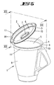
- This stable opening position is in a preferred embodiment, a vertical position of the lid, that is, a position in which a lid plane is set at a 90 ° angle to the vessel opening plane.
- further lid opening positions are possible in this regard, with further these opening positions are stable in a preferred embodiment, ie can only be canceled by user intervention.
- the stable opening position of the lid further preferably concerns a 30 °, 45 ° or even 75 ° position (with further reference to the planes of the lid and the vessel rim opening), with each further open position between a 0 ° position (FIG. Lid closure position) and a 90 ° position is stable, optionally also open positions beyond the 90 ° position addition, for example, a 100 ° - or 115 ° position of the lid.
- the stable Opening position of the lid is preferably freely selectable by the user with respect to the angular position to the vessel opening plane.
- a 15 ° opening position can be selected in order, for example, to counteract overcooking of the food in the vessel.
- the 90 ° position is used, for example, to have a free state inside the vessel, for example for stirring, addition of further ingredients or removal of the food.
- the stable opening position is achieved by clamping, wherein the outer edge of the vessel edge and an inner region of the vessel edge are supported at associated and facing portions of the lid profile interior at the same time, so further preferably under conditioning of the vessel outer edge of the overlap portion and the inner region of the vessel edge on the Support section, wherein more preferably the support areas are offset in height to each other.
- a protrusion projecting into the profile interior is formed which, in the closed state, is without engagement with the edge of the vessel. Accordingly, this bulge projects freely into the profile interior in the lid closure state, more preferably freely into the free space remaining above the vessel rim in the closed state. It can be further provided in this regard that isolated over the circumference of the lid edge, more preferably evenly distributed arranged bulges are provided. Alternatively, as further preferred, the bulge is provided circumferentially in the overlapping portion.
- This bulge is further preferably used to the effect that in a selected opening position of the lid, the bending of the edge of the vessel engages behind the bulge and thus in a preferred embodiment, the selected Lid opening position secures.
- the Radialfreikragschreib the edge of the vessel and the radial free dimension of the formed over the edge of the vessel free space and the extension of the bulge in the profile interior here determine the tightness or the locking torque, which is further selected so that it can be triggered by simple Deckelschwenk Gay relative to the edge of the vessel by the user , The user preferably feels the overflow of the projecting into the profile interior bulge, so this is the achieved stable opening position of the lid is conveyed.
- the abutment portions of the overlap portion and the support portion have a radial distance corresponding to at least the extent of the free-standing edge of the vessel, more preferably plus the wall thickness of the edge of the container, so that in a preferred embodiment, in particular in the lid closure position, a support of the support portion is achieved inside the wall edge of the vessel and a support of the Lid-side overlap portion radially outward on the outer edge of the free-standing edge of the vessel or the free-projecting angled portion.
- the contact zones on the lid are arranged one above the other, preferably vertically one above the other, while the contact zones on the vessel are arranged side by side, preferably horizontally next to one another. All contact zones are furthermore preferably arranged outside the medium-wetted region.
- the edge of the vessel below the free-standing angled portion has a step-like inward going recess.
- This recess forms in cross-section of a step whose step surface is vertically offset from the free-projecting edge of the vessel, the surfaces of fingerkragendem vessel edge and step parallel or at least approximately parallel.
- a horizontal orientation of the step surface ie an orientation transverse to the vessel longitudinal axis
- the vessel edge in an acute cross-section of 2 to 15 °, for example 10 ° to a horizontal occupies, this further to form a radially inwardly sloping surface. More preferably extends below the step, further starting from the radially inner edge of the step edge vertically downwards the optionally mediumbeetzmannte vessel wall.
- the support portion of the lid is arranged in a preferred embodiment in the lid closure position on the inner step surface (preferably horizontal surface) of the recess.
- the support section is seated in the lid closure position in a preferred embodiment on the step surface.
- the support portion may extend with a small vertical distance above the step surface, for example, with a vertical distance of 1 to 5 mm, in which case a support of the lid is achieved in the lid closure state alone on the overlap portion under support at the edge of the vessel.
- the support portion of the lid in the lid closure position in cross section in the step inside corner of the recess sits, so that more preferably in the lid closure position of the support portion is supported both in the vertical direction on the step surface and in the radial direction on the inner wall of the associated vessel edge wall ,
- the arrangement of the support section in cross-section in the stepped inner corner can also be chosen so that a small radial distance to the associated vessel edge wall and / or a small vertical distance to the associated step surface is left, which distances preferably 1 to 5 mm, more preferably less than 3 mm, more preferably less than 1 mm.
- the handling of the lid in particular the pivoting or setting up in the lid open position or the pivoting or placing in the lid closure position can be further promoted by expression of one or more of the above-described contact zones as an elastic element.
- at least a portion of the support portion and / or the overlap portion consists of a soft plastic, more preferably made of an elastic soft plastic.
- a lid made of a plastic material, in particular hard plastic material here offers a solution by production in two-component injection molding.
- the soft zones created thereby are formed, in particular, in the areas, more particularly in the support section, which come into contact with the facing areas of the edge of the vessel.
- this soft zone is at the same time designed as a sealing element, for cooperation with an associated edge section of the vessel, in particular in the cover closure position.
- the bulge may consist of such a soft plastic combinative or alternatively alternatively, so on, for example, when the lid as a plastic injection molded part by corresponding injection molding a soft plastic on the, the profile interior facing side of the overlap section.
- the non-destructive latching to achieve the stable lid opening position can be further improved.
- the arrangement of resilient or elastic ring elements can allow the erection seat by a pure press fit (rubber squeezer).
- the preferably provided sealing surfaces when parking the lid, in particular when setting up the lid and fixing the same are not contaminated at the edge of the vessel, in particular by running off the lid medium.
- the profile interior of the lid (preferably disregarding the projecting into the profile interior cross-section of the bulge) on a triangle oriented cross-sectional area, which cross-sectional area is substantially defined by the overlap portion and the angle thereto employed support portion, which sections two legs of the triangle forms, while the third leg of the triangle is an imaginary line between the cross-sectionally free edge of the overlap portion and the free edge of the support portion is formed.
- the described triangle of the cross-sectional area here is preferably not strictly geometric in nature, but rather preferably has projections and recesses with respect to the triangular limbs, for example by the preferably provided bulge.
- the vessel edge and the lid edge are rotationally symmetrical. So cover and edge of the vessel can be combined with each other in any direction of rotation.
- the installation position of the lid on the vessel is possible in undirected position, wherein preferably an unlimited number of erection combinations can be achieved.
- the necessary geometries for setting-up are arranged outside the medium space, wherein the possibly located on the lid medium is returned in the open position in the interior of the vessel.
- the ring-shaped according to the rotationally symmetric embodiment contact zones on the vessel and lid are responsible in their detail arrangement for the desired installation angle.
- a vessel 1 here designed as a mixing vessel for a food processor, for example, for a food processor according to DE 10 2005 028 758 .
- the content of this patent application is fully incorporated in the disclosure of the present invention, in particular with regard to the Rhakgefäßaussch, the arrangement of the mixing vessel in the food processor and the arrangement and optionally a lock of a lid on the mixing vessel, also for the purpose, features of this patent application in claims of the present invention to involve.
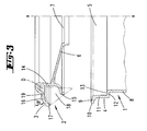
- the vessel 1 can be provided with a lid 2 which can be placed in a sealing manner.
- a lid edge 3 cooperates with a vessel edge 4, wherein further in the illustrated embodiment lid edge 3 and vessel edge 4 are formed rotationally symmetrical to a vessel vertical axis x.
- the lid 2 is rotatable relative to the vessel 1, so as to achieve a preferably latchable cover safety on the vessel 1.
- the lid 2 although not shown, the cover edge outside radially decelerating, more preferably diametrically opposite arranged collar portions, for cooperation with corresponding receptacles in the kitchen machine housing.
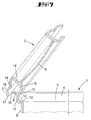
- the lid 2 further preferably has one, the vessel opening 5 in the lid closure position according to Fig. 1 covering lid bottom 6 on. This extends in a cross-section, starting from the edge of the lid 3 radially inward to the vessel vertical axis x sloping. Centered, ie further rotationally symmetric to the vertical axis x in the lid bottom 6, an opening 7 is provided, through which, for example, in the lid closure position further ingredients can be filled into the vessel 1.
- the vessel 1 further has a vessel wall 8.
- the edge of the vessel 4 is initially provided in the region of its free end viewed in cross-section with an angled portion 9 projecting radially outward.
- Their vertically upwardly facing surface extends from an outer edge 10 inclined radially inward, wherein in the illustrated embodiment, the angle of inclination in cross section approximately corresponds to that of the lid bottom 6 in the lid closure position.
- Radially inside the bend 9 is in a cross-section - at least with respect to the inner wall - vertically extending edge portion of the vessel 11 over. Its vertical dimension corresponds in the illustrated embodiment approximately to 1.5 times the Radialkeragschreib the bend 9th
- the radial extent corresponds approximately to the free-projecting length b of the bend 9.
- the vertically upper surface of the recess extends in a direction perpendicular to the vertical axis x of the vessel 1 extending plane, this forms a flat step surface 13 from.
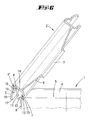
- the lid edge 3 of the lid 2 which is more preferably produced as a plastic injection-molded part, is formed as an outwardly open hollow profile. So is first in the Cross section provided a support portion 14. This extends in a lid closure position in cross-section at least approximately vertically, ie parallel to the vertical axis x of the vessel 1. Radially inside the lid portion 6 is integrally formed on the support portion 14.
- the extending below the lid bottom 5 region of the support portion 14 extends in cross section along a circular arc portion radially outward, wherein in the illustrated embodiment, a quarter circle is formed at its free, radially outwardly facing end again in the vertical direction downwardly extending support leg 15 of the support portion 14 connects.
- the region of the support section 14 that extends vertically upwards beyond the lid base in cross section initially forms a standing collar surrounding the lid base 6. Its vertically upwardly facing end merges into a radially outwardly directed overreaching section 16. This runs opposite to a vertical plane perpendicular to the vertical axis x horizontal plane at an acute angle ⁇ of about 30 ° with a downward pointing downward slope.
- the free end of the overlapping section 16 forms a cross-sectionally hook-like rear gripping section 17 whose radially inner surface extends vertically in cross-section, more preferably parallel to the support section 14.
- a bulge 19 projecting into the profile interior 18 is formed therein.
- This bulge 19 is formed in the illustrated embodiment by a corresponding change in profile of the Schugreifabiteses 17, wherein further the bulge 19 is selected in cross-section circular section.
- extension direction of the Schugreifabiteses 17 is left both before and behind the bulge 19 a rectilinear, stretched portion of the rear grip portion 17.
- the above-described profile of the lid edge 3 is given according to the rotationally symmetrical design of the lid 2 over the entire circumference of the lid edge 3.
- the configuration of the bulge 19 may be selected so that at overall cross-section rectilinearly stretched overreaching portion 16, the bulge 19 facing the inside, the profile interior 18 is sprayed further, for example, in the two-component injection method under gating a respect to the cover material softer plastic material.
- Such a bulge 19 can also be provided rotationally symmetrical.
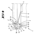
- Fig. 4 is shown in cross section the lid closure position.
- the lid is seated by means of its support section 14, in particular by means of the support foot 15, on the inside of the vessel on the associated step surface 13 of the cover-edge-side recess 12.
- the support leg 15 is positioned in the step inner corner, which also offers a radial positioning of the same in addition to the vertical cover positioning.
- a further, in particular radial support in the region of the vessel edge-side outer edge 10 can be achieved, which outer edge 10 is encompassed by the rear engagement section 17 of the cover-side overlap section 16.
- the contact areas of overlapping section 16 and supporting section 14 are vertically offset in height, so by the vertical distance between step surface 13 and the opening plane of the vessel 1 defined by the bend 9.
- the vessel edge section projects into the profile interior 18, the latter having a triangular-oriented surface in cross section, wherein the triangular surface D (schematically in FIG Fig. 3 shown) is bounded on the one hand by the Studentsgreifund support portions 14, 16, the corresponding triangular legs and on the other hand by an imaginary line connecting the support portion side support leg 15 and the overreaching portion Schugreifabites 17 connects, although no strict triangular geometry exists, due to the Vorund recesses the configuration of bulge 19, support leg 15 and its connection region to the support portion 14 and ultimately by the rear engagement portion 17th
- Another support is achieved in two other, in opposite directions of the direction of rotation of the lid edge 3 to the rear grip position in the region of the bulge 19 by here further support of the support portion 14, in particular of the support leg 15 at the peripheral contact zone of the vessel edge 4 in the transition region of the Angling 9 is given in the vessel edge portion 11 (see. Fig. 7 ).
- lid 2 and vessel 1 in any direction of rotation is possible both in the Deckelver gleich- and in the lid open position.
- cover 2 and cover edge 3 are outside the wetted with medium area of the lid 2, this in both the Deckelver gleich- and in the lid open position.
- the encircling support leg 15 of the lid 2 forms in the lid open position a drip edge, which faces the interior of the vessel 1, so that the return of any medium located on the underside of the lid is ensured in the vessel.
- the support section 14, in particular the extending below the cover bottom 6 section together with the support leg 15 is formed of a soft plastic, in particular of an elastic soft plastic. This is preferably molded in the manufacture of the lid in the plastic injection molding process, so that a total one-piece design is achieved.
- the flexible design of the support section 14 favors the installation of the lid 2 in the open position.
- the overflow of the bulge 19 is supported by a possible deflection of the flexible support portion 14.
- this is the support portion 14, in particular the support leg 15 at the same time formed as a sealing element.
Landscapes
- Engineering & Computer Science (AREA)
- Food Science & Technology (AREA)
- Mechanical Engineering (AREA)
- Closures For Containers (AREA)
Priority Applications (1)
| Application Number | Priority Date | Filing Date | Title |
|---|---|---|---|
| PL10175058T PL2298144T3 (pl) | 2009-09-16 | 2010-09-02 | Pojemnik, zwłaszcza pojemnik mieszający do maszyny kuchennej |
Applications Claiming Priority (1)
| Application Number | Priority Date | Filing Date | Title |
|---|---|---|---|
| DE102009041727A DE102009041727A1 (de) | 2009-09-16 | 2009-09-16 | Gefäß, insbesondere Rührgefäß für eine Küchenmaschine |
Publications (2)
| Publication Number | Publication Date |
|---|---|
| EP2298144A1 EP2298144A1 (de) | 2011-03-23 |
| EP2298144B1 true EP2298144B1 (de) | 2013-04-03 |
Family
ID=42989578
Family Applications (1)
| Application Number | Title | Priority Date | Filing Date |
|---|---|---|---|
| EP10175058A Not-in-force EP2298144B1 (de) | 2009-09-16 | 2010-09-02 | Gefäß, insbesondere Rührgefäß für eine Küchenmaschine |
Country Status (6)
| Country | Link |
|---|---|
| EP (1) | EP2298144B1 (pt) |
| CN (1) | CN102018458B (pt) |
| DE (1) | DE102009041727A1 (pt) |
| ES (1) | ES2408594T3 (pt) |
| PL (1) | PL2298144T3 (pt) |
| PT (1) | PT2298144E (pt) |
Families Citing this family (7)
| Publication number | Priority date | Publication date | Assignee | Title |
|---|---|---|---|---|
| DE102011078377A1 (de) * | 2011-06-30 | 2013-01-03 | BSH Bosch und Siemens Hausgeräte GmbH | Bearbeitungsgefäß mit einer Rührschüssel und einem Deckel |
| PL2813164T3 (pl) * | 2012-08-16 | 2016-01-29 | Vorwerk Co Interholding | Elektryczny robot kuchenny |
| US10448787B2 (en) * | 2013-04-08 | 2019-10-22 | Conair Corporation | Food processor having detachable spring-loaded lid |
| USD847558S1 (en) | 2017-12-12 | 2019-05-07 | Access Business Group International Llc | Preparation and cooking appliance |
| EP3814243A4 (en) * | 2018-06-29 | 2022-03-30 | Breville Pty Limited | LID FOR A FOOD PROCESSOR |
| DE102019211306A1 (de) * | 2019-07-30 | 2021-02-04 | BSH Hausgeräte GmbH | Deckeleinrichtung für ein Gefäß einer Küchenmaschine, Gefäß-Deckeleinrichtungs-Kombination und Küchenmaschine |
| ES2983755T3 (es) * | 2020-09-24 | 2024-10-24 | Vorwerk Co Interholding | Robot de cocina junto con procedimiento para tomar una muestra de comida |
Family Cites Families (5)
| Publication number | Priority date | Publication date | Assignee | Title |
|---|---|---|---|---|
| BR9803559A (pt) * | 1998-09-09 | 2000-05-09 | Arno Sa | Liquidificador com lâminas removìveis |
| DE20006093U1 (de) * | 2000-04-01 | 2000-09-14 | Jokey Plastik Gummersbach GmbH, 51645 Gummersbach | Kunststoffbehälter mit einrastbarem Deckel |
| WO2002013622A2 (de) * | 2000-08-16 | 2002-02-21 | Vorwerk & Co. | Küchenmaschine mit einem rührgefäss sowie verfahren zur herstellung von speiseeis |
| DE102005028758A1 (de) | 2005-06-22 | 2007-01-04 | Vorwerk & Co. Interholding Gmbh | Küchenmaschine mit einem Rührgefäß |
| DE102006028980A1 (de) * | 2006-06-23 | 2007-12-27 | Metallwarenfabrik Marktoberdorf Gmbh & Co. Kg | Gefäß, insbesondere Schüssel für Koch-, Anricht-, Aufbewahrungs- oder/und Servierzwecke und Deckel für ein solches Gefäß |
-
2009
- 2009-09-16 DE DE102009041727A patent/DE102009041727A1/de not_active Withdrawn
-
2010
- 2010-09-02 PT PT101750586T patent/PT2298144E/pt unknown
- 2010-09-02 EP EP10175058A patent/EP2298144B1/de not_active Not-in-force
- 2010-09-02 PL PL10175058T patent/PL2298144T3/pl unknown
- 2010-09-02 ES ES10175058T patent/ES2408594T3/es active Active
- 2010-09-15 CN CN201010282994.2A patent/CN102018458B/zh active Active
Also Published As
| Publication number | Publication date |
|---|---|
| CN102018458A (zh) | 2011-04-20 |
| CN102018458B (zh) | 2014-12-24 |
| PT2298144E (pt) | 2013-05-23 |
| EP2298144A1 (de) | 2011-03-23 |
| ES2408594T3 (es) | 2013-06-21 |
| PL2298144T3 (pl) | 2013-07-31 |
| DE102009041727A1 (de) | 2011-03-17 |
Similar Documents
| Publication | Publication Date | Title |
|---|---|---|
| EP2298144B1 (de) | Gefäß, insbesondere Rührgefäß für eine Küchenmaschine | |
| DE102011051149B4 (de) | Elektrisch betriebene Küchenmaschine mit einem Gargefäß | |
| EP2911561B1 (de) | Elektrisch betriebene küchenmaschine | |
| DE60314499T2 (de) | Kunststofffarbdose | |
| EP2875762B1 (de) | Rührgefäß für eine Küchenmaschine | |
| EP3513696B1 (de) | Küchenmaschine mit einem abdeckelement für ein zubereitunsgefäss | |
| CH699504A1 (de) | Getränkebereiter mit einem in ein Gefäss eingesetzten Einsatzteil. | |
| EP2064977B1 (de) | Küchenmaschine mit einem Rührgefäß | |
| EP2607136A1 (de) | Einrichtung zum dichten Verschließen eines Behälters | |
| EP3292806A1 (de) | Rührgefäss für eine elektromotorisch betriebene küchenmaschine | |
| EP2522263B1 (de) | Elektrisch betriebene Küchenmaschine mit einem Gargefäß | |
| EP2253256A2 (de) | Küchenmaschine mit einem Rührgefäß | |
| DE102010016667A1 (de) | Rührgefäß für eine Küchenmaschine | |
| DE102007060749A1 (de) | Küchenmaschine mit einem aufheizbaren Gefäß | |
| EP1670692B1 (de) | Behälter | |
| DE102010038003B4 (de) | Deckel für ein Gargefäß sowie auf einem topfförmigen Gargefäß aufsitzender Deckel | |
| EP3469969B1 (de) | Elektromotorisch betriebene küchenmaschine sowie rührgefäss und rührwerk dafür | |
| EP0792821B1 (de) | Schaumkopf | |
| EP1120073B1 (de) | Arbeitsbehälter für eine Küchenmaschine | |
| DE202022102226U1 (de) | Küchengerät mit Deckelhalter und Deckelhalter | |
| DE102012103877A1 (de) | Deckel für ein Gargefäß sowie Gargefäß mit einem Deckel | |
| DE2850724C2 (de) | Küchenmaschine | |
| CH688301A5 (de) | Dampfdruckkochtopf. | |
| DE9420827U1 (de) | Thermokanne | |
| DE4304689C2 (de) | Fritiergerät |
Legal Events
| Date | Code | Title | Description |
|---|---|---|---|
| PUAI | Public reference made under article 153(3) epc to a published international application that has entered the european phase |
Free format text: ORIGINAL CODE: 0009012 |
|
| AK | Designated contracting states |
Kind code of ref document: A1 Designated state(s): AL AT BE BG CH CY CZ DE DK EE ES FI FR GB GR HR HU IE IS IT LI LT LU LV MC MK MT NL NO PL PT RO SE SI SK SM TR |
|
| AX | Request for extension of the european patent |
Extension state: BA ME RS |
|
| 17P | Request for examination filed |
Effective date: 20110704 |
|
| GRAP | Despatch of communication of intention to grant a patent |
Free format text: ORIGINAL CODE: EPIDOSNIGR1 |
|
| RIC1 | Information provided on ipc code assigned before grant |
Ipc: A47J 43/07 20060101AFI20121026BHEP |
|
| GRAS | Grant fee paid |
Free format text: ORIGINAL CODE: EPIDOSNIGR3 |
|
| GRAA | (expected) grant |
Free format text: ORIGINAL CODE: 0009210 |
|
| RIN1 | Information on inventor provided before grant (corrected) |
Inventor name: ARNOLD, HANS-PETER Inventor name: DEGEN-BRAUN, BARBARA Inventor name: BRECH, OLIVER |
|
| AK | Designated contracting states |
Kind code of ref document: B1 Designated state(s): AL AT BE BG CH CY CZ DE DK EE ES FI FR GB GR HR HU IE IS IT LI LT LU LV MC MK MT NL NO PL PT RO SE SI SK SM TR |
|
| REG | Reference to a national code |
Ref country code: GB Ref legal event code: FG4D Free format text: NOT ENGLISH |
|
| REG | Reference to a national code |
Ref country code: CH Ref legal event code: EP Ref country code: AT Ref legal event code: REF Ref document number: 604163 Country of ref document: AT Kind code of ref document: T Effective date: 20130415 |
|
| REG | Reference to a national code |
Ref country code: IE Ref legal event code: FG4D Free format text: LANGUAGE OF EP DOCUMENT: GERMAN |
|
| REG | Reference to a national code |
Ref country code: PT Ref legal event code: SC4A Free format text: AVAILABILITY OF NATIONAL TRANSLATION Effective date: 20130516 |
|
| REG | Reference to a national code |
Ref country code: DE Ref legal event code: R096 Ref document number: 502010002755 Country of ref document: DE Effective date: 20130529 |
|
| REG | Reference to a national code |
Ref country code: ES Ref legal event code: FG2A Ref document number: 2408594 Country of ref document: ES Kind code of ref document: T3 Effective date: 20130621 |
|
| REG | Reference to a national code |
Ref country code: PL Ref legal event code: T3 |
|
| PG25 | Lapsed in a contracting state [announced via postgrant information from national office to epo] |
Ref country code: SI Free format text: LAPSE BECAUSE OF FAILURE TO SUBMIT A TRANSLATION OF THE DESCRIPTION OR TO PAY THE FEE WITHIN THE PRESCRIBED TIME-LIMIT Effective date: 20130403 |
|
| REG | Reference to a national code |
Ref country code: NL Ref legal event code: VDEP Effective date: 20130403 |
|
| REG | Reference to a national code |
Ref country code: LT Ref legal event code: MG4D |
|
| PG25 | Lapsed in a contracting state [announced via postgrant information from national office to epo] |
Ref country code: GR Free format text: LAPSE BECAUSE OF FAILURE TO SUBMIT A TRANSLATION OF THE DESCRIPTION OR TO PAY THE FEE WITHIN THE PRESCRIBED TIME-LIMIT Effective date: 20130704 Ref country code: FI Free format text: LAPSE BECAUSE OF FAILURE TO SUBMIT A TRANSLATION OF THE DESCRIPTION OR TO PAY THE FEE WITHIN THE PRESCRIBED TIME-LIMIT Effective date: 20130403 Ref country code: NL Free format text: LAPSE BECAUSE OF FAILURE TO SUBMIT A TRANSLATION OF THE DESCRIPTION OR TO PAY THE FEE WITHIN THE PRESCRIBED TIME-LIMIT Effective date: 20130403 Ref country code: SE Free format text: LAPSE BECAUSE OF FAILURE TO SUBMIT A TRANSLATION OF THE DESCRIPTION OR TO PAY THE FEE WITHIN THE PRESCRIBED TIME-LIMIT Effective date: 20130403 Ref country code: IS Free format text: LAPSE BECAUSE OF FAILURE TO SUBMIT A TRANSLATION OF THE DESCRIPTION OR TO PAY THE FEE WITHIN THE PRESCRIBED TIME-LIMIT Effective date: 20130803 Ref country code: NO Free format text: LAPSE BECAUSE OF FAILURE TO SUBMIT A TRANSLATION OF THE DESCRIPTION OR TO PAY THE FEE WITHIN THE PRESCRIBED TIME-LIMIT Effective date: 20130703 Ref country code: LT Free format text: LAPSE BECAUSE OF FAILURE TO SUBMIT A TRANSLATION OF THE DESCRIPTION OR TO PAY THE FEE WITHIN THE PRESCRIBED TIME-LIMIT Effective date: 20130403 |
|
| PG25 | Lapsed in a contracting state [announced via postgrant information from national office to epo] |
Ref country code: HR Free format text: LAPSE BECAUSE OF FAILURE TO SUBMIT A TRANSLATION OF THE DESCRIPTION OR TO PAY THE FEE WITHIN THE PRESCRIBED TIME-LIMIT Effective date: 20130403 Ref country code: LV Free format text: LAPSE BECAUSE OF FAILURE TO SUBMIT A TRANSLATION OF THE DESCRIPTION OR TO PAY THE FEE WITHIN THE PRESCRIBED TIME-LIMIT Effective date: 20130403 Ref country code: BG Free format text: LAPSE BECAUSE OF FAILURE TO SUBMIT A TRANSLATION OF THE DESCRIPTION OR TO PAY THE FEE WITHIN THE PRESCRIBED TIME-LIMIT Effective date: 20130703 Ref country code: CY Free format text: LAPSE BECAUSE OF FAILURE TO SUBMIT A TRANSLATION OF THE DESCRIPTION OR TO PAY THE FEE WITHIN THE PRESCRIBED TIME-LIMIT Effective date: 20130403 |
|
| PGFP | Annual fee paid to national office [announced via postgrant information from national office to epo] |
Ref country code: IT Payment date: 20130930 Year of fee payment: 4 |
|
| PG25 | Lapsed in a contracting state [announced via postgrant information from national office to epo] |
Ref country code: CZ Free format text: LAPSE BECAUSE OF FAILURE TO SUBMIT A TRANSLATION OF THE DESCRIPTION OR TO PAY THE FEE WITHIN THE PRESCRIBED TIME-LIMIT Effective date: 20130403 Ref country code: DK Free format text: LAPSE BECAUSE OF FAILURE TO SUBMIT A TRANSLATION OF THE DESCRIPTION OR TO PAY THE FEE WITHIN THE PRESCRIBED TIME-LIMIT Effective date: 20130403 Ref country code: SK Free format text: LAPSE BECAUSE OF FAILURE TO SUBMIT A TRANSLATION OF THE DESCRIPTION OR TO PAY THE FEE WITHIN THE PRESCRIBED TIME-LIMIT Effective date: 20130403 Ref country code: EE Free format text: LAPSE BECAUSE OF FAILURE TO SUBMIT A TRANSLATION OF THE DESCRIPTION OR TO PAY THE FEE WITHIN THE PRESCRIBED TIME-LIMIT Effective date: 20130403 |
|
| PLBE | No opposition filed within time limit |
Free format text: ORIGINAL CODE: 0009261 |
|
| STAA | Information on the status of an ep patent application or granted ep patent |
Free format text: STATUS: NO OPPOSITION FILED WITHIN TIME LIMIT |
|
| PG25 | Lapsed in a contracting state [announced via postgrant information from national office to epo] |
Ref country code: RO Free format text: LAPSE BECAUSE OF FAILURE TO SUBMIT A TRANSLATION OF THE DESCRIPTION OR TO PAY THE FEE WITHIN THE PRESCRIBED TIME-LIMIT Effective date: 20130403 |
|
| 26N | No opposition filed |
Effective date: 20140106 |
|
| BERE | Be: lapsed |
Owner name: VORWERK & CO. INTERHOLDING G.M.B.H. Effective date: 20130930 |
|
| REG | Reference to a national code |
Ref country code: DE Ref legal event code: R097 Ref document number: 502010002755 Country of ref document: DE Effective date: 20140106 |
|
| PG25 | Lapsed in a contracting state [announced via postgrant information from national office to epo] |
Ref country code: MC Free format text: LAPSE BECAUSE OF FAILURE TO SUBMIT A TRANSLATION OF THE DESCRIPTION OR TO PAY THE FEE WITHIN THE PRESCRIBED TIME-LIMIT Effective date: 20130403 |
|
| REG | Reference to a national code |
Ref country code: PT Ref legal event code: MM4A Free format text: LAPSE DUE TO NON-PAYMENT OF FEES Effective date: 20140602 |
|
| REG | Reference to a national code |
Ref country code: DE Ref legal event code: R119 Ref document number: 502010002755 Country of ref document: DE Effective date: 20140401 |
|
| REG | Reference to a national code |
Ref country code: FR Ref legal event code: ST Effective date: 20140530 |
|
| REG | Reference to a national code |
Ref country code: IE Ref legal event code: MM4A |
|
| PG25 | Lapsed in a contracting state [announced via postgrant information from national office to epo] |
Ref country code: BE Free format text: LAPSE BECAUSE OF NON-PAYMENT OF DUE FEES Effective date: 20130930 Ref country code: IE Free format text: LAPSE BECAUSE OF NON-PAYMENT OF DUE FEES Effective date: 20130902 |
|
| PG25 | Lapsed in a contracting state [announced via postgrant information from national office to epo] |
Ref country code: FR Free format text: LAPSE BECAUSE OF NON-PAYMENT OF DUE FEES Effective date: 20130930 Ref country code: DE Free format text: LAPSE BECAUSE OF NON-PAYMENT OF DUE FEES Effective date: 20140401 Ref country code: PT Free format text: LAPSE BECAUSE OF NON-PAYMENT OF DUE FEES Effective date: 20140602 |
|
| REG | Reference to a national code |
Ref country code: ES Ref legal event code: FD2A Effective date: 20141007 |
|
| PG25 | Lapsed in a contracting state [announced via postgrant information from national office to epo] |
Ref country code: PL Free format text: LAPSE BECAUSE OF NON-PAYMENT OF DUE FEES Effective date: 20130902 |
|
| REG | Reference to a national code |
Ref country code: PL Ref legal event code: LAPE |
|
| PG25 | Lapsed in a contracting state [announced via postgrant information from national office to epo] |
Ref country code: ES Free format text: LAPSE BECAUSE OF NON-PAYMENT OF DUE FEES Effective date: 20130903 |
|
| REG | Reference to a national code |
Ref country code: CH Ref legal event code: PL |
|
| GBPC | Gb: european patent ceased through non-payment of renewal fee |
Effective date: 20140902 |
|
| PG25 | Lapsed in a contracting state [announced via postgrant information from national office to epo] |
Ref country code: SM Free format text: LAPSE BECAUSE OF FAILURE TO SUBMIT A TRANSLATION OF THE DESCRIPTION OR TO PAY THE FEE WITHIN THE PRESCRIBED TIME-LIMIT Effective date: 20130403 |
|
| PG25 | Lapsed in a contracting state [announced via postgrant information from national office to epo] |
Ref country code: MT Free format text: LAPSE BECAUSE OF FAILURE TO SUBMIT A TRANSLATION OF THE DESCRIPTION OR TO PAY THE FEE WITHIN THE PRESCRIBED TIME-LIMIT Effective date: 20130403 Ref country code: TR Free format text: LAPSE BECAUSE OF FAILURE TO SUBMIT A TRANSLATION OF THE DESCRIPTION OR TO PAY THE FEE WITHIN THE PRESCRIBED TIME-LIMIT Effective date: 20130403 |
|
| PG25 | Lapsed in a contracting state [announced via postgrant information from national office to epo] |
Ref country code: MK Free format text: LAPSE BECAUSE OF FAILURE TO SUBMIT A TRANSLATION OF THE DESCRIPTION OR TO PAY THE FEE WITHIN THE PRESCRIBED TIME-LIMIT Effective date: 20130403 Ref country code: CH Free format text: LAPSE BECAUSE OF NON-PAYMENT OF DUE FEES Effective date: 20140930 Ref country code: LU Free format text: LAPSE BECAUSE OF NON-PAYMENT OF DUE FEES Effective date: 20130902 Ref country code: LI Free format text: LAPSE BECAUSE OF NON-PAYMENT OF DUE FEES Effective date: 20140930 Ref country code: HU Free format text: LAPSE BECAUSE OF FAILURE TO SUBMIT A TRANSLATION OF THE DESCRIPTION OR TO PAY THE FEE WITHIN THE PRESCRIBED TIME-LIMIT; INVALID AB INITIO Effective date: 20100902 Ref country code: GB Free format text: LAPSE BECAUSE OF NON-PAYMENT OF DUE FEES Effective date: 20140902 |
|
| PG25 | Lapsed in a contracting state [announced via postgrant information from national office to epo] |
Ref country code: IT Free format text: LAPSE BECAUSE OF NON-PAYMENT OF DUE FEES Effective date: 20140902 |
|
| REG | Reference to a national code |
Ref country code: AT Ref legal event code: MM01 Ref document number: 604163 Country of ref document: AT Kind code of ref document: T Effective date: 20150902 |
|
| PG25 | Lapsed in a contracting state [announced via postgrant information from national office to epo] |
Ref country code: AT Free format text: LAPSE BECAUSE OF NON-PAYMENT OF DUE FEES Effective date: 20150902 |
|
| PG25 | Lapsed in a contracting state [announced via postgrant information from national office to epo] |
Ref country code: AL Free format text: LAPSE BECAUSE OF FAILURE TO SUBMIT A TRANSLATION OF THE DESCRIPTION OR TO PAY THE FEE WITHIN THE PRESCRIBED TIME-LIMIT Effective date: 20130403 |