EP2296851B1 - Papierlocher - Google Patents
Papierlocher Download PDFInfo
- Publication number
- EP2296851B1 EP2296851B1 EP20090779775 EP09779775A EP2296851B1 EP 2296851 B1 EP2296851 B1 EP 2296851B1 EP 20090779775 EP20090779775 EP 20090779775 EP 09779775 A EP09779775 A EP 09779775A EP 2296851 B1 EP2296851 B1 EP 2296851B1
- Authority
- EP
- European Patent Office
- Prior art keywords
- base part
- paper punch
- cutout
- paper
- punch according
- Prior art date
- Legal status (The legal status is an assumption and is not a legal conclusion. Google has not performed a legal analysis and makes no representation as to the accuracy of the status listed.)
- Active
Links
Images

Classifications
-
- B—PERFORMING OPERATIONS; TRANSPORTING
- B26—HAND CUTTING TOOLS; CUTTING; SEVERING
- B26F—PERFORATING; PUNCHING; CUTTING-OUT; STAMPING-OUT; SEVERING BY MEANS OTHER THAN CUTTING
- B26F1/00—Perforating; Punching; Cutting-out; Stamping-out; Apparatus therefor
- B26F1/32—Hand-held perforating or punching apparatus, e.g. awls
- B26F1/36—Punching or perforating pliers
-
- B—PERFORMING OPERATIONS; TRANSPORTING
- B26—HAND CUTTING TOOLS; CUTTING; SEVERING
- B26D—CUTTING; DETAILS COMMON TO MACHINES FOR PERFORATING, PUNCHING, CUTTING-OUT, STAMPING-OUT OR SEVERING
- B26D7/00—Details of apparatus for cutting, cutting-out, stamping-out, punching, perforating, or severing by means other than cutting
-
- Y—GENERAL TAGGING OF NEW TECHNOLOGICAL DEVELOPMENTS; GENERAL TAGGING OF CROSS-SECTIONAL TECHNOLOGIES SPANNING OVER SEVERAL SECTIONS OF THE IPC; TECHNICAL SUBJECTS COVERED BY FORMER USPC CROSS-REFERENCE ART COLLECTIONS [XRACs] AND DIGESTS
- Y10—TECHNICAL SUBJECTS COVERED BY FORMER USPC
- Y10T—TECHNICAL SUBJECTS COVERED BY FORMER US CLASSIFICATION
- Y10T83/00—Cutting
- Y10T83/222—With receptacle or support for cut product
-
- Y—GENERAL TAGGING OF NEW TECHNOLOGICAL DEVELOPMENTS; GENERAL TAGGING OF CROSS-SECTIONAL TECHNOLOGIES SPANNING OVER SEVERAL SECTIONS OF THE IPC; TECHNICAL SUBJECTS COVERED BY FORMER USPC CROSS-REFERENCE ART COLLECTIONS [XRACs] AND DIGESTS
- Y10—TECHNICAL SUBJECTS COVERED BY FORMER USPC
- Y10T—TECHNICAL SUBJECTS COVERED BY FORMER US CLASSIFICATION
- Y10T83/00—Cutting
- Y10T83/869—Means to drive or to guide tool
- Y10T83/8821—With simple rectilinear reciprocating motion only
- Y10T83/8841—Tool driver movable relative to tool support
- Y10T83/885—Fixed axis lever
Definitions
- the invention relates to a paper punch according to the preamble of claim 1.
- Known paper punches have a bottom part on which the documents to be punched are deposited on a support surface.
- About the bottom part of a hand lever is limited pivotally mounted about a pivot axis, which serves the depression of puncture tools, such as punches or punches.
- the punching tools are slidably mounted, for example, in the pivot axis of the hand lever, extending from the bottom upwardly extending side cheeks and punching the depression of the hand lever from lying on the support documents written round paper shreds, which are pushed through holes in the support surface in a Schnitzelwanne the bottom part ,
- punching the paper punch is either with a footprint on the underside of its bottom part on a flat surface, such as a table top, and the user presses down in the direction of the back of the bottom part protruding free end of the hand lever.
- the muscle groups of the upper arm and the upper body of the user are mainly claimed, which must spend a large force due to the long lever arm formed by his arm.
- Such a paper punch is from the DE 706 832 known.
- the invention is based on the idea that the user can engage with his fingers in the gripping cutout of the bottom part, while the palm attacks at the free end of the hand lever.
- the bottom part can be easily attacked even if the paper punch is on a table top.
- the distance from the ceiling wall to the free end of the hand lever is less than from the footprint to the free end of the hand lever, so that a hole process in which the paper punch is held in the hand, can also be performed by users with smaller hands.
- the paper punch can remain standing on the tabletop during the punching operation, so that for punching operations in which larger forces are required, the use of the muscle groups of the hand and forearm with the use of the muscle groups of the upper arm and the upper body can be combined.
- the gripping cut-out has a height of at least 10 mm, preferably of at least 15 mm.
- the height of the gripping cutout is measured from a running through the footprint level, which corresponds to the plane of the table top, from in the vertical direction. By this measure, the fingers of the user can be easily inserted into the gripping cutout when the punch is still on the table top.
- the gripping cutout has a width of at least 70 mm, preferably of at least 80 mm. The width is measured in the horizontal direction, parallel to the pivot axis of the hand lever. This measure allows the user to insert all fingers except the thumb into the gripping cutout.
- the gripping cutout extends over the entire width of the bottom part.
- the gripping cutout is expediently bounded laterally by side walls of the bottom part which extend in the direction of the rear side. A lateral slipping of the fingers is prevented.
- the bottom part preferably has a perforated lower part made of sheet metal which has the ceiling wall and a plastic Schnitzel trough having the footprint, the Schnitzel trough and the punched lower part being releasably connected to one another. This allows easy emptying of the Schnitzel pan.
- the transverse wall is expedient part of the Schnitzelwanne, and a central portion of the transverse wall is preferably curved forward. This reflects the fact that the middle fingers are longer than the outer fingers.
- the ceiling wall expediently has an open-edged cutout, in which a lot of Schnitzelwanne is engaged. At this point, the user can attack to release the chip pan from the punch bottom.
- the gripping cutout is lined by an extension of the Schnitzel pan, which adjoins the top wall and optionally on the side walls. The user then attacks on the made of plastic, preferably made of soft plastic, extension of the Schnitzelwanne, which is perceived as pleasant, as if he had to attack on the ceiling wall formed from sheet metal.
- the paper punch 10 shown in the drawing has a bottom part 12 from which extend from a front portion 14 in the direction of its rear side 16 two mutually spaced side cheeks 18 upwards.
- a pivot axis 20 is mounted, about which a hand lever 22 is limited pivot.
- the free end 24 of the hand lever 22 extends at a distance from the bottom part 12 obliquely upward toward the rear 16.
- the bottom part 12 has a perforated lower part 30 made of sheet metal, which has a ceiling wall 32 and extending from a front side 34 to the back 16, opposite the ceiling wall 32 downwardly bent side walls 36.
- the ceiling wall 32 is provided in the front region 14 with the support surface 28 for the documents.
- a Schnitzelwanne 38 made of soft plastic is snapped onto the punch lower part 30 from below, which has on its underside a flat footprint 40 for setting up the paper punch 10 on a table top.
- the Schnitzelwanne 38 is snapped onto the punch lower part 30 and forms with this a receiving space for the punched out paper shreds, which are pressed by the punch holes 26 through holes in the support surface 28.
- a stop rail 42 slidably guided, which facilitates positioning of the writing material on the support surface 28.
- the bottom part 12 has an open towards its rear side 16 towards the handle cutout 44 which is bounded at the top by the rear end of the ceiling wall 32 and to the sides by the rear ends of the side walls 36.
- the gripping cutout 44 is lined by an extension 46 of the Schnitzelwanne 38, which rests against the inner surfaces of the ceiling wall 32 and the side walls 36.
- a batch 48 of the Schnitzelwanne 38 is also engaged in an open-edge cutout 50 of the ceiling wall 32 and can be easily taken to release the connection between the punch lower part 30 and the Schnitzelwanne 38.
- the gripping cutout 44 is bounded by a transverse wall 52 of the Schnitzelwanne 38, which also limits the receiving space for the shredded paper to the rear.
- the transverse wall 52 is arched at its center between the side walls 36 toward the front.
- the gripping cutout 44 a user can engage with four fingers to grasp the paper punch 10 so that he can press the free end 24 of the hand lever 22 with the palm of your hand down.
- the gripping cutout 44 has a height h of approximately 15 mm, which is measured between the plane running through the set-up surface 40 and the extension 46 of the Schnitzel pan 38 abutting the inner side of the ceiling wall 32. Between the adjacent to the inner surfaces of the side walls 36 games of the extension 46, the width b of the gripping cutout 44 is about 80 mm.
- the side cheeks 18 extend approximately to the transverse wall 52 and become flatter towards the rear, so that they have an appealing design.
- the invention relates to a paper punch 10 having a bottom portion 12 having on its underside a footprint 40 for placement on a table top, with at least two with respect to the bottom portion 12 vertically slidably mounted hole tools 26 for punching documents and a hand lever 22 for applying the punching tools 26, which is mounted on a front, a support surface 28 for the documents having portion 14 of the bottom part 12 limited pivotally about a pivot axis 20 and the free end 24 extends at a distance from the bottom part 12 toward a rear side 16 of the bottom part 12.
- the bottom part 12 has a gripping cutout 44 which is open toward its rear side 16 and is bounded at the top by a ceiling wall 32 extending at a distance from the set-up surface 40 and at the front by a transverse wall 52.
Landscapes
- Life Sciences & Earth Sciences (AREA)
- Forests & Forestry (AREA)
- Engineering & Computer Science (AREA)
- Mechanical Engineering (AREA)
- Perforating, Stamping-Out Or Severing By Means Other Than Cutting (AREA)
Description
- Die Erfindung betrifft einen Papierlocher gemäß Oberbegriff des Anspruchs 1.
- Bekannte Papierlocher weisen ein Bodenteil auf, auf dem das zu lochende Schriftgut auf einer Auflagefläche abgelegt wird. Über dem Bodenteil ist ein Handhebel um eine Schwenkachse begrenzt verschwenkbar gelagert, der dem Niederdrücken von Lochwerkzeugen, wie Lochstempeln oder Lochpfeifen, dient. Die Lochwerkzeuge sind verschiebbar beispielsweise in die Schwenkachse des Handhebels tragenden, sich vom Bodenteil nach oben erstreckenden Seitenwangen gelagert und stanzen beim Niederdrücken des Handhebels aus dem auf der Auflagefläche liegenden Schriftgut runde Papierschnitzel aus, die durch Löcher in der Auflagefläche in eine Schnitzelwanne des Bodenteils hindurchgedrückt werden. Beim Lochvorgang steht der Papierlocher entweder mit einer Aufstellfläche an der Unterseite seines Bodenteils auf einer ebenen Fläche, beispielsweise einer Tischplatte, und der Benutzer drückt das in Richtung der Rückseite des Bodenteils vorstehende freie Ende des Handhebels nieder. Bei dieser Benutzungsart werden überwiegend die Muskelgruppen des Oberarms und des Oberkörpers des Benutzers beansprucht, wobei dieser aufgrund des durch seinen Arm gebildeten langen Hebelarms eine große Kraft aufwenden muß. Oftmals ist es erforderlich, dass der Benutzer aufsteht und sich so mit seinem Gewicht auf den Handhebel stützen kann. Eine andere Art der Benutzung besteht darin, den Papierlocher in die Hand zu nehmen, wobei die Finger an der Aufstellfläche und der Handballen am freien Ende des Handhebels angreifen. Beim Lochvorgang werden dann überwiegend die Muskelgruppen der Hand und des Unterarms beansprucht, wobei der Benutzer auch im Sitzen eine hohe Kraft ausüben kann. Bei den bekannten Lochern, deren Bodenteil mit seiner gesamten Unterseite auf der Tischplatte aufliegt, wird diese einfachere Handhabung jedoch oft als unvorteilhaft empfunden, da zum Anheben des Papierlochers meist beide Hände benötigt werden.
- Ein solcher Papierlocher ist aus der
DE 706 832 bekannt. - Es ist daher Aufgabe der Erfindung, einen Papierlocher der eingangs genannten Art derart weiterzubilden, dass er einfacher handhabbar ist.
- Die Aufgabe wird erfindungsgemäß durch einen Papierlocher mit den Merkmalen des Anspruchs 1 gelöst. Vorteilhafte Weiterbildungen der Erfindung sind Gegenstand der abhängigen Ansprüche.
- Der Erfindung liegt der Gedanke zugrunde, dass der Benutzer mit seinen Fingern in den Greifausschnitt des Bodenteils eingreifen kann, während der Handballen am freien Ende des Handhebels angreift. So kann das Bodenteil auch dann auf einfache Weise untergriffen werden, wenn der Papierlocher auf einer Tischplatte steht. Desweiteren ist der Abstand von der Deckenwand zum freien Ende des Handhebels geringer als von der Aufstellfläche zum freien Ende des Handhebels, so dass ein Lochvorgang, bei dem der Papierlocher in der Hand gehalten wird, auch von Benutzern mit kleineren Händen ausgeführt werden kann. Desweiteren kann der Papierlocher auch während des Lochvorgangs auf der Tischplatte stehen bleiben, so dass für Lochvorgänge, bei denen größere Kräfte erforderlich sind, der Einsatz der Muskelgruppen der Hand und des Unterarms mit dem Einsatz der Muskelgruppen des Oberarms und des Oberkörpers kombiniert werden kann.
- Erfindungsgemäß weist der Greifausschnitt eine Höhe von mindestens 10 mm, vorzugsweise von mindestens 15 mm, auf. Die Höhe des Greifausschnitts wird von einer durch die Aufstellfläche verlaufenden Ebene, die der Ebene der Tischplatte entspricht, aus in vertikaler Richtung gemessen. Durch diese Maßnahme können die Finger des Benutzers bequem in den Greifausschnitt eingeführt werden, wenn der Locher noch auf der Tischplatte steht. Der Greifausschnitt weist eine Breite von mindestens 70 mm, vorzugsweise von mindestens 80 mm auf. Die Breite wird in horizontaler Richtung gemessen, parallel zur Schwenkachse des Handhebels. Durch diese Maßnahme wird ermöglicht, dass der Benutzer alle Finger mit Ausnahme des Daumens in den Greifausschnitt einführen kann. Vorzugsweise erstreckt sich der Greifausschnitt über die gesamte Breite des Bodenteils.
- Der Greifausschnitt wird zweckmäßig seitlich durch sich in Richtung zur Rückseite erstreckende Seitenwände des Bodenteils begrenzt. Ein seitliches Abrutschen der Finger wird dadurch verhindert. Vorzugsweise weist das Bodenteil ein die Deckenwand aufweisendes Locherunterteil aus Blech und eine die Aufstellfläche aufweisende Schnitzelwanne aus Kunststoff auf, wobei die Schnitzelwanne und das Locherunterteil lösbar miteinander verbunden sind. Dies ermöglicht ein einfaches Entleeren der Schnitzelwanne. Die Querwand ist zweckmäßig Bestandteil der Schnitzelwanne, und eine mittlere Partie der Querwand ist vorzugsweise nach vorne gewölbt. Dadurch wird der Tatsache Rechnung getragen, dass die mittleren Finger länger sind als die äußeren Finger.
- Die Deckenwand weist zweckmäßig einen randoffenen Ausschnitt auf, in den eine Partie der Schnitzelwanne eingerastet ist. An dieser Stelle kann der Benutzer angreifen, um die Schnitzelwanne vom Locherunterteil zu lösen. Vorteilhaft ist der Greifausschnitt durch einen an der Deckenwand und gegebenenfalls an den Seitenwänden anliegenden Fortsatz der Schnitzelwanne ausgekleidet. Der Benutzer greift dann an dem aus Kunststoff, vorzugsweise aus weichem Kunststoff, bestehenden Fortsatz der Schnitzelwanne an, was als angenehmer empfunden wird, als wenn er an der aus Blech gebildeten Deckenwand angreifen müsste.
- Im Folgenden wird die Erfindung anhand eines in der Zeichnung schematisch dargestellten Ausführungsbeispiels näher erläutert. Es zeigen
- Fig. 1
- einen Papierlocher in perspektivischer Ansicht von schräg vorne und
- Fig. 2
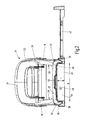
- den Papierlocher gemäß
Fig. 1 in einer Ansicht von hinten. - Der in der Zeichnung dargestellte Papierlocher 10 weist ein Bodenteil 12 auf, von dem aus sich von einem vorderen Bereich 14 in Richtung zu seiner Rückseite 16 zwei im Abstand zueinander verlaufende Seitenwangen 18 nach oben erstrecken. In den Seitenwangen 18 ist eine Schwenkachse 20 gelagert, um die ein Handhebel 22 begrenzt verschwenkbar ist. Das freie Ende 24 des Handhebels 22 erstreckt sich im Abstand zum Bodenteil 12 schräg nach oben in Richtung zu dessen Rückseite 16. Durch ein Niederdrücken des freien Endes 24 des Handhebels 22 auf das Bodenteil 12 zu werden zwei in den Seitenwangen 18 verschiebbar gelagerte Lochstempel 26 beaufschlagt, die runde Papierschnitzel aus auf einer Auflagefläche 28 im vorderen Bereich 14 des Bodenteils 12 aufliegendem Schriftgut ausstanzen.
- Das Bodenteil 12 weist ein Locherunterteil 30 aus Blech auf, das eine Deckenwand 32 sowie sich von einer Vorderseite 34 zur Rückseite 16 erstreckende, gegenüber der Deckenwand 32 nach unten abgebogene Seitenwände 36 aufweist. Die Deckenwand 32 ist im vorderen Bereich 14 mit der Auflagefläche 28 für das Schriftgut versehen. Als weiterer Bestandteil des Bodenteils 12 ist auf das Locherunterteil 30 von unten her eine Schnitzelwanne 38 aus weichem Kunststoff aufgerastet, die an ihrer Unterseite eine ebene Aufstellfläche 40 zum Aufstellen des Papierlochers 10 auf eine Tischplatte aufweist. Die Schnitzelwanne 38 ist auf das Locherunterteil 30 aufgerastet und bildet mit diesem einen Aufnahmeraum für die ausgestanzten Papierschnitzel, die von den Lochstempeln 26 durch Löcher in der Auflagefläche 28 durchgedrückt werden. In der Schnitzelwanne 38 ist eine Anschlagschiene 42 verschiebbar geführt, die ein Positionieren des Schriftguts auf der Auflagefläche 28 erleichtert.
- Das Bodenteil 12 weist einen zu seiner Rückseite 16 hin offenen Greifausschnitt 44 auf, der nach oben hin durch das hintere Ende der Deckenwand 32 und zu den Seiten hin durch die hinteren Enden der Seitenwände 36 begrenzt wird. Der Greifausschnitt 44 wird durch einen Fortsatz 46 der Schnitzelwanne 38 ausgekleidet, der an den Innenflächen der Deckenwand 32 und der Seitenwände 36 anliegt. Eine Partie 48 der Schnitzelwanne 38 ist zudem in einen randoffenen Ausschnitt 50 der Deckenwand 32 eingerastet und kann zum Lösen der Verbindung zwischen dem Locherunterteil 30 und der Schnitzelwanne 38 leicht ergriffen werden. Nach vorne hin wird der Greifausschnitt 44 durch eine Querwand 52 der Schnitzelwanne 38 begrenzt, die zudem den Aufnahmeraum für die Papierschnitzel nach hinten begrenzt. Die Querwand 52 ist an ihrer Mitte zwischen den Seitenwänden 36 nach vorne hin gewölbt.
- In den Greifausschnitt 44 kann ein Benutzer mit vier Fingern eingreifen, um den Papierlocher 10 so zu fassen, dass er das freie Ende 24 des Handhebels 22 mit dem Handballen nach unten drücken kann. Zu diesem Zweck weist der Greifausschnitt 44 eine Höhe h von ca. 15 mm auf, die zwischen der durch die Aufstellfläche 40 verlaufenden Ebene und dem an der Innenseite der Deckenwand 32 anliegenden Fortsatz 46 der Schnitzelwanne 38 gemessen wird. Zwischen den an den Innenflächen der Seitenwände 36 anliegenden Partien des Fortsatzes 46 beträgt die Breite b des Greifausschnitts 44 ca. 80 mm. Die Seitenwangen 18 erstrecken sich bis etwa zur Querwand 52 und werden nach hinten hin flacher, so dass sie ein ansprechendes Design aufweisen.
- Zusammenfassend ist folgendes festzuhalten:
- Die Erfindung betrifft einen Papierlocher 10 mit einem Bodenteil 12, das an seiner Unterseite eine Aufstellfläche 40 zum Aufstellen auf eine Tischplatte aufweist, mit mindestens zwei bezüglich des Bodenteils 12 vertikal verschiebbar gelagerten Lochwerkzeugen 26 zum Lochen von Schriftgut und mit einem Handhebel 22 zum Beaufschlagen der Lochwerkzeuge 26, der über einem vorderen, eine Auflagefläche 28 für das Schriftgut aufweisenden Bereich 14 des Bodenteils 12 um eine Schwenkachse 20 begrenzt verschwenkbar gelagert ist und dessen freies Ende 24 sich im Abstand zum Bodenteil 12 in Richtung zu einer Rückseite 16 des Bodenteils 12 erstreckt. Erfindungsgemäß ist vorgesehen, dass das Bodenteil 12 einen zu seiner Rückseite 16 hin offenen Greifausschnitt 44 aufweist, der nach oben hin durch eine im Abstand zur Aufstellfläche 40 verlaufende Deckenwand 32 und nach vorne hin durch eine Querwand 52 begrenzt wird.
Claims (9)
- Papierlocher mit einem Bodenteil (12), das an seiner Unterseite eine Aufstellfläche (40) zum Aufstellen auf eine Tischplatte aufweist, mit mindestens zwei vertikal bezüglich des Bodenteils (12) verschiebbar gelagerten Lochwerkzeugen (26) zum Lochen von Schriftgut und mit einem Handhebel (22) zum Beaufschlagen der Lochwerkzeuge (26), der über einem vorderen, eine Auflagefläche (28) für das Schriftgut aufweisenden Bereich (14) des Bodenteils (12) um eine Schwenkachse (20) begrenzt verschwenkbar gelagert ist und dessen freies Ende (24) sich im Abstand zum Bodenteil (12) in Richtung zu einer Rückseite (16) des Bodenteils (12) erstreckt, wobei das Bodenteil (12) einen zu seiner Rückseite (16) hin offenen Greifausschnitt (44) aufweist, der nach oben hin durch eine im Abstand zur Aufstellfläche (40) verlaufende Deckenwand (32) und nach vorne hin durch eine Querwand (52) begrenzt wird, dadurch gekennzeichnet, dass der Greifausschnitt (44) eine Höhe von mindestens 10 mm und eine Breite von mindestens 70 mm aufweist und dass der Greifausschnitt (44) seitlich durch sich in Richtung zur Rückseite (16) erstreckende Seitenwände (36) des Bodenteils (12) begrenzt wird.
- Papierlocher nach Anspruch 1, dadurch gekennzeichnet, dass der Greifausschnitt (44) eine Höhe von mindestens 15 mm aufweist.
- Papierlocher nach Anspruch 1 oder 2, dadurch gekennzeichnet, dass der Greifausschnitt (44) eine Breite von mindestens 80 mm aufweist.
- Papierlocher nach einem der vorangehenden Ansprüche, dadurch gekennzeichnet, dass sich der Greifausschnitt (44) über die gesamte Breite des Bodenteils (12) erstreckt.
- Papierlocher nach einem der vorangehenden Ansprüche, dadurch gekennzeichnet, dass das Bodenteil (12) ein die Deckenwand (32) aufweisendes Locherunterteil (30) aus Blech und eine die Aufstellfläche (40) aufweisende Schnitzelwanne (38) aus Kunststoff aufweist, wobei die Schnitzelwanne (38) und das Locherunterteil (30) lösbar miteinander verbunden sind.
- Papierlocher nach Anspruch 5, dadurch gekennzeichnet, dass die Querwand (52) Bestandteil der Schnitzelwanne (38) ist.
- Papierlocher nach einem der vorangehenden Ansprüche, dadurch gekennzeichnet, dass eine mittlere Partie der Querwand (52) nach vorne gewölbt ist.
- Papierlocher einem der Ansprüche 5 bis 7, dadurch gekennzeichnet, dass die Deckenwand (32) einen randoffenen Ausschnitt (50) aufweist, in den eine Partie (48) der Schnitzelwanne (38) eingerastet ist.
- Papierlocher nach einem der Ansprüche 5 bis 8, dadurch gekennzeichnet, dass der Greifausschnitt (44) durch einen an der Deckenwand (32) und gegebenenfalls an den Seitenwänden (36) anliegenden Fortsatz (46) der Schnitzelwanne (38) ausgekleidet ist.
Applications Claiming Priority (2)
| Application Number | Priority Date | Filing Date | Title |
|---|---|---|---|
| DE102008033606.8A DE102008033606B4 (de) | 2008-07-17 | 2008-07-17 | Papierlocher |
| PCT/EP2009/057419 WO2010006865A1 (de) | 2008-07-17 | 2009-06-16 | Papierlocher |
Publications (2)
| Publication Number | Publication Date |
|---|---|
| EP2296851A1 EP2296851A1 (de) | 2011-03-23 |
| EP2296851B1 true EP2296851B1 (de) | 2014-09-24 |
Family
ID=41019454
Family Applications (1)
| Application Number | Title | Priority Date | Filing Date |
|---|---|---|---|
| EP20090779775 Active EP2296851B1 (de) | 2008-07-17 | 2009-06-16 | Papierlocher |
Country Status (7)
| Country | Link |
|---|---|
| US (1) | US8573105B2 (de) |
| EP (1) | EP2296851B1 (de) |
| CN (1) | CN102099166A (de) |
| CA (1) | CA2731461A1 (de) |
| DE (1) | DE102008033606B4 (de) |
| ES (1) | ES2524265T3 (de) |
| WO (1) | WO2010006865A1 (de) |
Family Cites Families (14)
| Publication number | Priority date | Publication date | Assignee | Title |
|---|---|---|---|---|
| DE461552C (de) * | 1927-07-26 | 1928-06-23 | Soennecken Fa F | Papierlocher mit auf einer Grundplatte schwingbar gelagertem Druckbuegel und in Gleitlagern der Grundplatte ruhenden Lochstiften |
| DE706832C (de) * | 1940-05-08 | 1941-06-06 | Feinmechanik G M B H | Locher fuer Briefe u. dgl. |
| US3859726A (en) * | 1973-05-07 | 1975-01-14 | Toppan Moore Business Forms Co | Letter punch |
| US5632188A (en) * | 1995-02-24 | 1997-05-27 | Clix Products, Inc. | Ergopunch |
| US6439093B1 (en) * | 1998-07-01 | 2002-08-27 | Michael Anthony Davies | Sheet punch device |
| DE19912043A1 (de) * | 1999-03-17 | 2000-09-21 | Esselte Leitz Gmbh & Co Kg | Papierlocher |
| DE19912042A1 (de) * | 1999-03-17 | 2000-09-21 | Esselte Leitz Gmbh & Co Kg | Abfallwanne für Brieflocher |
| CN2415896Y (zh) | 2000-04-19 | 2001-01-24 | 深圳市龙岗区龙岗南约旗标实业厂 | 标尺弹性定位打孔机 |
| GB2384737A (en) * | 2002-01-31 | 2003-08-06 | Acco Uk Ltd | Hole punch having a telescopic paper guide |
| JP2003245896A (ja) | 2002-02-22 | 2003-09-02 | Kokuyo Co Ltd | 穿孔用具 |
| US7856912B2 (en) * | 2005-09-07 | 2010-12-28 | Ellison Educational Equipment, Inc. | Manually operated portable die cutting machine |
| WO2007038439A1 (en) * | 2005-09-26 | 2007-04-05 | Acco Brands Usa Llc | Punch with adjustable punch pad |
| DE102006027009B4 (de) * | 2006-06-08 | 2011-09-15 | Esselte Leitz Gmbh & Co. Kg | Papierlocher |
| JP5253751B2 (ja) * | 2007-03-30 | 2013-07-31 | プラス株式会社 | 穿孔パンチ |
-
2008
- 2008-07-17 DE DE102008033606.8A patent/DE102008033606B4/de active Active
-
2009
- 2009-06-16 ES ES09779775.7T patent/ES2524265T3/es active Active
- 2009-06-16 US US12/737,413 patent/US8573105B2/en not_active Expired - Fee Related
- 2009-06-16 WO PCT/EP2009/057419 patent/WO2010006865A1/de not_active Ceased
- 2009-06-16 CN CN2009801275742A patent/CN102099166A/zh active Pending
- 2009-06-16 CA CA 2731461 patent/CA2731461A1/en not_active Abandoned
- 2009-06-16 EP EP20090779775 patent/EP2296851B1/de active Active
Also Published As
| Publication number | Publication date |
|---|---|
| EP2296851A1 (de) | 2011-03-23 |
| WO2010006865A1 (de) | 2010-01-21 |
| CN102099166A (zh) | 2011-06-15 |
| DE102008033606A1 (de) | 2010-01-21 |
| US20110107893A1 (en) | 2011-05-12 |
| US8573105B2 (en) | 2013-11-05 |
| DE102008033606B4 (de) | 2019-05-09 |
| ES2524265T3 (es) | 2014-12-04 |
| CA2731461A1 (en) | 2010-01-21 |
Similar Documents
| Publication | Publication Date | Title |
|---|---|---|
| DE29825182U1 (de) | Vorrichtung zum Entfernen von Ausbrechteilen aus einem Werkstoffbogen o.dgl. | |
| EP2277369A1 (de) | Multifunktionsgriff | |
| DE4429775A1 (de) | Ringbinder mit Papierlochungsmechanismus | |
| DE202008015612U1 (de) | Gerät zum Zuschneiden von Paneelen und Verbundplatten wie Bodenbeläge aus Laminat | |
| EP0067973B1 (de) | Locher für Blatt- und Folienförmiges Material | |
| EP3137262B1 (de) | Heftklammergerät | |
| DE20118241U1 (de) | Papierlocher | |
| DE102008033606B4 (de) | Papierlocher | |
| DE20309766U1 (de) | Feststellvorrichtung für die Papierarretierleiste eines Papierschneiders | |
| DE60300989T2 (de) | Locher | |
| DE2947367A1 (de) | Ablagevorrichtung zum ablegen losen gelochten schriftgutes | |
| DE102011015473A1 (de) | Papierlocher | |
| WO2016055081A1 (de) | Tragbare, handbetriebene schneideinrichtung | |
| DE102006027009B4 (de) | Papierlocher | |
| EP1366252B1 (de) | Mischbrett | |
| DE202010017955U1 (de) | Vorrichtung zum Ausbrechen | |
| DE202007018124U1 (de) | Handbetätigbare Müllpresse | |
| DE102024113399A1 (de) | Messerschlitten; Messer mit Messerschlitten | |
| DE29808441U1 (de) | Einloch-Locher | |
| EP2107973A2 (de) | Verfahren und vorrichtung zum abheftbarmachen von seiten | |
| DE10323611A1 (de) | Pressvorrichtung für Behälter | |
| DE102011050944A1 (de) | Vorrichtung zur Vorbereitung von Würsten und Set mit iener solchen Vorrichtung sowie Verwendung einer solchen Vorrichtung | |
| DE7902625U1 (de) | Geraet zum heften und lochen von schriftstuecken | |
| DE20001164U1 (de) | Schere zum Schneiden von Pizza und Blechkuchen | |
| DE29825180U1 (de) | Vorrichtung zum Entfernen von Ausbrechteilen aus einem Werkstoffbogen o.dgl. |
Legal Events
| Date | Code | Title | Description |
|---|---|---|---|
| PUAI | Public reference made under article 153(3) epc to a published international application that has entered the european phase |
Free format text: ORIGINAL CODE: 0009012 |
|
| 17P | Request for examination filed |
Effective date: 20101209 |
|
| AK | Designated contracting states |
Kind code of ref document: A1 Designated state(s): AT BE BG CH CY CZ DE DK EE ES FI FR GB GR HR HU IE IS IT LI LT LU LV MC MK MT NL NO PL PT RO SE SI SK TR |
|
| AX | Request for extension of the european patent |
Extension state: AL BA RS |
|
| DAX | Request for extension of the european patent (deleted) | ||
| GRAP | Despatch of communication of intention to grant a patent |
Free format text: ORIGINAL CODE: EPIDOSNIGR1 |
|
| INTG | Intention to grant announced |
Effective date: 20140516 |
|
| GRAS | Grant fee paid |
Free format text: ORIGINAL CODE: EPIDOSNIGR3 |
|
| GRAA | (expected) grant |
Free format text: ORIGINAL CODE: 0009210 |
|
| AK | Designated contracting states |
Kind code of ref document: B1 Designated state(s): AT BE BG CH CY CZ DE DK EE ES FI FR GB GR HR HU IE IS IT LI LT LU LV MC MK MT NL NO PL PT RO SE SI SK TR |
|
| REG | Reference to a national code |
Ref country code: GB Ref legal event code: FG4D Free format text: NOT ENGLISH |
|
| REG | Reference to a national code |
Ref country code: CH Ref legal event code: EP |
|
| REG | Reference to a national code |
Ref country code: AT Ref legal event code: REF Ref document number: 688391 Country of ref document: AT Kind code of ref document: T Effective date: 20141015 |
|
| REG | Reference to a national code |
Ref country code: IE Ref legal event code: FG4D Free format text: LANGUAGE OF EP DOCUMENT: GERMAN |
|
| REG | Reference to a national code |
Ref country code: DE Ref legal event code: R096 Ref document number: 502009010017 Country of ref document: DE Effective date: 20141106 |
|
| REG | Reference to a national code |
Ref country code: ES Ref legal event code: FG2A Ref document number: 2524265 Country of ref document: ES Kind code of ref document: T3 Effective date: 20141204 |
|
| REG | Reference to a national code |
Ref country code: NL Ref legal event code: T3 |
|
| PG25 | Lapsed in a contracting state [announced via postgrant information from national office to epo] |
Ref country code: NO Free format text: LAPSE BECAUSE OF FAILURE TO SUBMIT A TRANSLATION OF THE DESCRIPTION OR TO PAY THE FEE WITHIN THE PRESCRIBED TIME-LIMIT Effective date: 20141224 Ref country code: SE Free format text: LAPSE BECAUSE OF FAILURE TO SUBMIT A TRANSLATION OF THE DESCRIPTION OR TO PAY THE FEE WITHIN THE PRESCRIBED TIME-LIMIT Effective date: 20140924 Ref country code: FI Free format text: LAPSE BECAUSE OF FAILURE TO SUBMIT A TRANSLATION OF THE DESCRIPTION OR TO PAY THE FEE WITHIN THE PRESCRIBED TIME-LIMIT Effective date: 20140924 Ref country code: LT Free format text: LAPSE BECAUSE OF FAILURE TO SUBMIT A TRANSLATION OF THE DESCRIPTION OR TO PAY THE FEE WITHIN THE PRESCRIBED TIME-LIMIT Effective date: 20140924 Ref country code: GR Free format text: LAPSE BECAUSE OF FAILURE TO SUBMIT A TRANSLATION OF THE DESCRIPTION OR TO PAY THE FEE WITHIN THE PRESCRIBED TIME-LIMIT Effective date: 20141225 |
|
| REG | Reference to a national code |
Ref country code: DE Ref legal event code: R082 Ref document number: 502009010017 Country of ref document: DE Representative=s name: PATENTANWAELTE BREGENZER UND REULE PARTNERSCHA, DE |
|
| REG | Reference to a national code |
Ref country code: LT Ref legal event code: MG4D |
|
| PG25 | Lapsed in a contracting state [announced via postgrant information from national office to epo] |
Ref country code: CY Free format text: LAPSE BECAUSE OF FAILURE TO SUBMIT A TRANSLATION OF THE DESCRIPTION OR TO PAY THE FEE WITHIN THE PRESCRIBED TIME-LIMIT Effective date: 20140924 Ref country code: HR Free format text: LAPSE BECAUSE OF FAILURE TO SUBMIT A TRANSLATION OF THE DESCRIPTION OR TO PAY THE FEE WITHIN THE PRESCRIBED TIME-LIMIT Effective date: 20140924 Ref country code: LV Free format text: LAPSE BECAUSE OF FAILURE TO SUBMIT A TRANSLATION OF THE DESCRIPTION OR TO PAY THE FEE WITHIN THE PRESCRIBED TIME-LIMIT Effective date: 20140924 |
|
| REG | Reference to a national code |
Ref country code: FR Ref legal event code: GC Effective date: 20150310 |
|
| PG25 | Lapsed in a contracting state [announced via postgrant information from national office to epo] |
Ref country code: SK Free format text: LAPSE BECAUSE OF FAILURE TO SUBMIT A TRANSLATION OF THE DESCRIPTION OR TO PAY THE FEE WITHIN THE PRESCRIBED TIME-LIMIT Effective date: 20140924 Ref country code: CZ Free format text: LAPSE BECAUSE OF FAILURE TO SUBMIT A TRANSLATION OF THE DESCRIPTION OR TO PAY THE FEE WITHIN THE PRESCRIBED TIME-LIMIT Effective date: 20140924 Ref country code: RO Free format text: LAPSE BECAUSE OF FAILURE TO SUBMIT A TRANSLATION OF THE DESCRIPTION OR TO PAY THE FEE WITHIN THE PRESCRIBED TIME-LIMIT Effective date: 20140924 Ref country code: IS Free format text: LAPSE BECAUSE OF FAILURE TO SUBMIT A TRANSLATION OF THE DESCRIPTION OR TO PAY THE FEE WITHIN THE PRESCRIBED TIME-LIMIT Effective date: 20150124 Ref country code: EE Free format text: LAPSE BECAUSE OF FAILURE TO SUBMIT A TRANSLATION OF THE DESCRIPTION OR TO PAY THE FEE WITHIN THE PRESCRIBED TIME-LIMIT Effective date: 20140924 Ref country code: PT Free format text: LAPSE BECAUSE OF FAILURE TO SUBMIT A TRANSLATION OF THE DESCRIPTION OR TO PAY THE FEE WITHIN THE PRESCRIBED TIME-LIMIT Effective date: 20150126 |
|
| PG25 | Lapsed in a contracting state [announced via postgrant information from national office to epo] |
Ref country code: PL Free format text: LAPSE BECAUSE OF FAILURE TO SUBMIT A TRANSLATION OF THE DESCRIPTION OR TO PAY THE FEE WITHIN THE PRESCRIBED TIME-LIMIT Effective date: 20140924 |
|
| REG | Reference to a national code |
Ref country code: DE Ref legal event code: R097 Ref document number: 502009010017 Country of ref document: DE |
|
| PG25 | Lapsed in a contracting state [announced via postgrant information from national office to epo] |
Ref country code: DK Free format text: LAPSE BECAUSE OF FAILURE TO SUBMIT A TRANSLATION OF THE DESCRIPTION OR TO PAY THE FEE WITHIN THE PRESCRIBED TIME-LIMIT Effective date: 20140924 |
|
| PLBE | No opposition filed within time limit |
Free format text: ORIGINAL CODE: 0009261 |
|
| STAA | Information on the status of an ep patent application or granted ep patent |
Free format text: STATUS: NO OPPOSITION FILED WITHIN TIME LIMIT |
|
| PG25 | Lapsed in a contracting state [announced via postgrant information from national office to epo] |
Ref country code: IT Free format text: LAPSE BECAUSE OF FAILURE TO SUBMIT A TRANSLATION OF THE DESCRIPTION OR TO PAY THE FEE WITHIN THE PRESCRIBED TIME-LIMIT Effective date: 20140924 |
|
| 26N | No opposition filed |
Effective date: 20150625 |
|
| PG25 | Lapsed in a contracting state [announced via postgrant information from national office to epo] |
Ref country code: MC Free format text: LAPSE BECAUSE OF FAILURE TO SUBMIT A TRANSLATION OF THE DESCRIPTION OR TO PAY THE FEE WITHIN THE PRESCRIBED TIME-LIMIT Effective date: 20140924 |
|
| REG | Reference to a national code |
Ref country code: CH Ref legal event code: PL |
|
| GBPC | Gb: european patent ceased through non-payment of renewal fee |
Effective date: 20150616 |
|
| PG25 | Lapsed in a contracting state [announced via postgrant information from national office to epo] |
Ref country code: SI Free format text: LAPSE BECAUSE OF FAILURE TO SUBMIT A TRANSLATION OF THE DESCRIPTION OR TO PAY THE FEE WITHIN THE PRESCRIBED TIME-LIMIT Effective date: 20140924 Ref country code: LU Free format text: LAPSE BECAUSE OF FAILURE TO SUBMIT A TRANSLATION OF THE DESCRIPTION OR TO PAY THE FEE WITHIN THE PRESCRIBED TIME-LIMIT Effective date: 20150616 |
|
| REG | Reference to a national code |
Ref country code: IE Ref legal event code: MM4A |
|
| PG25 | Lapsed in a contracting state [announced via postgrant information from national office to epo] |
Ref country code: CH Free format text: LAPSE BECAUSE OF NON-PAYMENT OF DUE FEES Effective date: 20150630 Ref country code: IE Free format text: LAPSE BECAUSE OF NON-PAYMENT OF DUE FEES Effective date: 20150616 Ref country code: LI Free format text: LAPSE BECAUSE OF NON-PAYMENT OF DUE FEES Effective date: 20150630 Ref country code: GB Free format text: LAPSE BECAUSE OF NON-PAYMENT OF DUE FEES Effective date: 20150616 |
|
| REG | Reference to a national code |
Ref country code: FR Ref legal event code: PLFP Year of fee payment: 8 |
|
| REG | Reference to a national code |
Ref country code: AT Ref legal event code: MM01 Ref document number: 688391 Country of ref document: AT Kind code of ref document: T Effective date: 20150616 |
|
| PG25 | Lapsed in a contracting state [announced via postgrant information from national office to epo] |
Ref country code: AT Free format text: LAPSE BECAUSE OF NON-PAYMENT OF DUE FEES Effective date: 20150616 |
|
| PG25 | Lapsed in a contracting state [announced via postgrant information from national office to epo] |
Ref country code: MT Free format text: LAPSE BECAUSE OF FAILURE TO SUBMIT A TRANSLATION OF THE DESCRIPTION OR TO PAY THE FEE WITHIN THE PRESCRIBED TIME-LIMIT Effective date: 20140924 |
|
| PG25 | Lapsed in a contracting state [announced via postgrant information from national office to epo] |
Ref country code: HU Free format text: LAPSE BECAUSE OF FAILURE TO SUBMIT A TRANSLATION OF THE DESCRIPTION OR TO PAY THE FEE WITHIN THE PRESCRIBED TIME-LIMIT; INVALID AB INITIO Effective date: 20090616 Ref country code: BG Free format text: LAPSE BECAUSE OF FAILURE TO SUBMIT A TRANSLATION OF THE DESCRIPTION OR TO PAY THE FEE WITHIN THE PRESCRIBED TIME-LIMIT Effective date: 20140924 |
|
| REG | Reference to a national code |
Ref country code: FR Ref legal event code: PLFP Year of fee payment: 9 |
|
| REG | Reference to a national code |
Ref country code: FR Ref legal event code: RG Effective date: 20170726 |
|
| PG25 | Lapsed in a contracting state [announced via postgrant information from national office to epo] |
Ref country code: TR Free format text: LAPSE BECAUSE OF FAILURE TO SUBMIT A TRANSLATION OF THE DESCRIPTION OR TO PAY THE FEE WITHIN THE PRESCRIBED TIME-LIMIT Effective date: 20140924 |
|
| REG | Reference to a national code |
Ref country code: DE Ref legal event code: R082 Ref document number: 502009010017 Country of ref document: DE Representative=s name: PATENTANWAELTE BREGENZER UND REULE PARTNERSCHA, DE Ref country code: DE Ref legal event code: R081 Ref document number: 502009010017 Country of ref document: DE Owner name: LEITZ ACCO BRANDS GMBH & CO KG, DE Free format text: FORMER OWNER: ESSELTE LEITZ GMBH & CO. KG, 70469 STUTTGART, DE |
|
| REG | Reference to a national code |
Ref country code: FR Ref legal event code: PLFP Year of fee payment: 10 |
|
| PG25 | Lapsed in a contracting state [announced via postgrant information from national office to epo] |
Ref country code: MK Free format text: LAPSE BECAUSE OF FAILURE TO SUBMIT A TRANSLATION OF THE DESCRIPTION OR TO PAY THE FEE WITHIN THE PRESCRIBED TIME-LIMIT Effective date: 20140924 |
|
| REG | Reference to a national code |
Ref country code: NL Ref legal event code: HC Owner name: LEITZ ACCO BRANDS GMBH & CO KG; DE Free format text: DETAILS ASSIGNMENT: CHANGE OF OWNER(S), CHANGE OF OWNER(S) NAME; FORMER OWNER NAME: ESSELTE LEITZ GMBH & CO. KG Effective date: 20180814 |
|
| REG | Reference to a national code |
Ref country code: ES Ref legal event code: PC2A Owner name: LEITZ ACCO BRANDS GMBH & CO. KG Effective date: 20181207 Ref country code: BE Ref legal event code: HC Owner name: LEITZ ACCO BRANDS GMBH & CO KG; DE Free format text: DETAILS ASSIGNMENT: CHANGE OF OWNER(S), CHANGEMENT DE NOM DU PROPRIETAIRE; FORMER OWNER NAME: ESSELTE LEITZ GMBH & CO. KG Effective date: 20181015 |
|
| PGFP | Annual fee paid to national office [announced via postgrant information from national office to epo] |
Ref country code: BE Payment date: 20220620 Year of fee payment: 14 |
|
| P01 | Opt-out of the competence of the unified patent court (upc) registered |
Effective date: 20230524 |
|
| REG | Reference to a national code |
Ref country code: BE Ref legal event code: MM Effective date: 20230630 |
|
| PG25 | Lapsed in a contracting state [announced via postgrant information from national office to epo] |
Ref country code: BE Free format text: LAPSE BECAUSE OF NON-PAYMENT OF DUE FEES Effective date: 20230630 |
|
| PGFP | Annual fee paid to national office [announced via postgrant information from national office to epo] |
Ref country code: DE Payment date: 20250429 Year of fee payment: 17 |
|
| PGFP | Annual fee paid to national office [announced via postgrant information from national office to epo] |
Ref country code: NL Payment date: 20250618 Year of fee payment: 17 |
|
| PGFP | Annual fee paid to national office [announced via postgrant information from national office to epo] |
Ref country code: FR Payment date: 20250624 Year of fee payment: 17 |
|
| PGFP | Annual fee paid to national office [announced via postgrant information from national office to epo] |
Ref country code: ES Payment date: 20250728 Year of fee payment: 17 |