EP2295348B1 - Förderkette - Google Patents
Förderkette Download PDFInfo
- Publication number
- EP2295348B1 EP2295348B1 EP10173834.2A EP10173834A EP2295348B1 EP 2295348 B1 EP2295348 B1 EP 2295348B1 EP 10173834 A EP10173834 A EP 10173834A EP 2295348 B1 EP2295348 B1 EP 2295348B1
- Authority
- EP
- European Patent Office
- Prior art keywords
- conveyor belt
- belt according
- segments
- conveyor
- support
- Prior art date
- Legal status (The legal status is an assumption and is not a legal conclusion. Google has not performed a legal analysis and makes no representation as to the accuracy of the status listed.)
- Active
Links
Images

Classifications
-
- B—PERFORMING OPERATIONS; TRANSPORTING
- B65—CONVEYING; PACKING; STORING; HANDLING THIN OR FILAMENTARY MATERIAL
- B65G—TRANSPORT OR STORAGE DEVICES, e.g. CONVEYORS FOR LOADING OR TIPPING, SHOP CONVEYOR SYSTEMS OR PNEUMATIC TUBE CONVEYORS
- B65G17/00—Conveyors having an endless traction element, e.g. a chain, transmitting movement to a continuous or substantially-continuous load-carrying surface or to a series of individual load-carriers; Endless-chain conveyors in which the chains form the load-carrying surface
- B65G17/24—Conveyors having an endless traction element, e.g. a chain, transmitting movement to a continuous or substantially-continuous load-carrying surface or to a series of individual load-carriers; Endless-chain conveyors in which the chains form the load-carrying surface comprising a series of rollers which are moved, e.g. over a supporting surface, by the traction element to effect conveyance of loads or load-carriers
-
- B—PERFORMING OPERATIONS; TRANSPORTING
- B65—CONVEYING; PACKING; STORING; HANDLING THIN OR FILAMENTARY MATERIAL
- B65G—TRANSPORT OR STORAGE DEVICES, e.g. CONVEYORS FOR LOADING OR TIPPING, SHOP CONVEYOR SYSTEMS OR PNEUMATIC TUBE CONVEYORS
- B65G17/00—Conveyors having an endless traction element, e.g. a chain, transmitting movement to a continuous or substantially-continuous load-carrying surface or to a series of individual load-carriers; Endless-chain conveyors in which the chains form the load-carrying surface
- B65G17/06—Conveyors having an endless traction element, e.g. a chain, transmitting movement to a continuous or substantially-continuous load-carrying surface or to a series of individual load-carriers; Endless-chain conveyors in which the chains form the load-carrying surface having a load-carrying surface formed by a series of interconnected, e.g. longitudinal, links, plates, or platforms
- B65G17/08—Conveyors having an endless traction element, e.g. a chain, transmitting movement to a continuous or substantially-continuous load-carrying surface or to a series of individual load-carriers; Endless-chain conveyors in which the chains form the load-carrying surface having a load-carrying surface formed by a series of interconnected, e.g. longitudinal, links, plates, or platforms the surface being formed by the traction element
-
- B—PERFORMING OPERATIONS; TRANSPORTING
- B65—CONVEYING; PACKING; STORING; HANDLING THIN OR FILAMENTARY MATERIAL
- B65G—TRANSPORT OR STORAGE DEVICES, e.g. CONVEYORS FOR LOADING OR TIPPING, SHOP CONVEYOR SYSTEMS OR PNEUMATIC TUBE CONVEYORS
- B65G17/00—Conveyors having an endless traction element, e.g. a chain, transmitting movement to a continuous or substantially-continuous load-carrying surface or to a series of individual load-carriers; Endless-chain conveyors in which the chains form the load-carrying surface
- B65G17/30—Details; Auxiliary devices
- B65G17/38—Chains or like traction elements; Connections between traction elements and load-carriers
- B65G17/40—Chains acting as load-carriers
-
- B—PERFORMING OPERATIONS; TRANSPORTING
- B65—CONVEYING; PACKING; STORING; HANDLING THIN OR FILAMENTARY MATERIAL
- B65G—TRANSPORT OR STORAGE DEVICES, e.g. CONVEYORS FOR LOADING OR TIPPING, SHOP CONVEYOR SYSTEMS OR PNEUMATIC TUBE CONVEYORS
- B65G17/00—Conveyors having an endless traction element, e.g. a chain, transmitting movement to a continuous or substantially-continuous load-carrying surface or to a series of individual load-carriers; Endless-chain conveyors in which the chains form the load-carrying surface
- B65G17/06—Conveyors having an endless traction element, e.g. a chain, transmitting movement to a continuous or substantially-continuous load-carrying surface or to a series of individual load-carriers; Endless-chain conveyors in which the chains form the load-carrying surface having a load-carrying surface formed by a series of interconnected, e.g. longitudinal, links, plates, or platforms
- B65G17/067—Conveyors having an endless traction element, e.g. a chain, transmitting movement to a continuous or substantially-continuous load-carrying surface or to a series of individual load-carriers; Endless-chain conveyors in which the chains form the load-carrying surface having a load-carrying surface formed by a series of interconnected, e.g. longitudinal, links, plates, or platforms the load carrying surface being formed by plates or platforms attached to more than one traction element
Definitions
- the invention relates to a conveyor belt, in particular for a pasteuriser, the type explained in the preamble of claim 1.
- Such a conveyor belt is from the DE 10 2004 021 262 A1 known.
- the known conveyor belt is designed for an endless circulation around two spaced rollers and serves to transport filled containers, such as bottles or glasses, through a pasteurizer, where pasteurization of the contents of the containers takes place by the action of heat for a certain time.
- the known conveyor belt is constructed of individual segments, each segment having one or more mounting brackets which are connected together to form a support grid. Through the bracket extending rods that extend across the entire width transversely to the conveying direction of the conveyor belt and both the segments of a transversely to the conveying direction extending transverse row connect together and serve as a hinge for relative movement of the adjacent segments in a longitudinal direction to the conveying direction series.
- These rods also serve as storage for support rollers, which are arranged under selected segments and these and thus support the entire conveyor belt on a support.
- a plastic top is attached, which forms the conveying surface.
- the conveying surface is formed by a small distance adjacent and upright plastic webs whose narrow sides form the conveying surface. To ensure that the containers rest on the conveying surface without tilting, the distances between the plastic webs are relatively narrow. If glass breakage occurs inside the pasteurizer, glass fragments may make the conveying surface jagged or even become wedged between the plastic webs, damaging the conveyor belt.
- the US Pat. No. 3,220,535 A. further describes an endless conveyor belt with plate-shaped conveyor segments. These are mounted on both sides of lateral sliding blocks or rollers and driven by laterally arranged outside the sliding blocks or rollers chains.
- the conveyor segments of the conveyor belt are formed continuously transversely to the transport direction.
- the WO 2007/034 289 A1 further describes an endless conveyor belt having laterally continuous band segments passing over stationary mounted rollers.
- the invention has for its object to provide a conveyor belt that is less susceptible to damage.
- the support rollers used in the known conveyor belt can easily carry the higher weight of a metal conveying surface without an excessively increased drive energy expended must become.
- the combination of the support rollers with a conveying surface made of metal thus leads to a conveyor belt, which can handle very well with glass breakage, without the previous disadvantages of steel or metal conveyor belts, ie a high demand for drive energy due to the greatly increased weight occurs.
- the support rollers need not necessarily be provided under each segment, wherein preferably the transverse outer segments are supported by the rollers.
- the conveyor surfaces of adjacent segments in the transverse direction are substantially side by side without a gap. This can preferably be achieved by means of a cross-connection device between segments which are transverse to the conveying direction. Alternatively or additionally, clamping devices may be provided at the ends of propeller shafts connecting adjacent segments in the transverse row.
- the support roller also sit on the propeller shafts.
- Laterally provided support and guide bracket which are arranged on successively in the conveying direction of cardan shafts, ensure a smooth and straight running of the conveyor belt according to the invention.
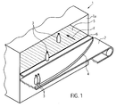
- Fig. 1 shows in a highly schematic, perspective view of the inlet region of a pasteuriser 1, which may be conventional except for the conveyor belt.
- the pasteurizer 1 is supplied via a conventional conveyor belt 2, the container 3, shown bottles, to the inlet region 1 a of the pasteurizer 1 brings.
- the containers are preferably glass containers which experience the glass breaking problems described in the prior art.
- the invention is to be used for containers of all kinds and does not necessarily have to be realized in a pasteuriser.
- the usual inlet rail 4 is provided which directs the arriving on the conveyor belt 2 container 3 in the inlet region 1 a.
- a conveyor belt 5 is provided, onto which the containers 3 are pushed by the conveyor belt 2 via a transfer plate 6.
- the overflow plate is smooth, without openings and preferably made of spring steel.
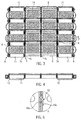
- the conveyor belt 5 inside the pasteuriser is in the Fig. 2 to 6 explained in more detail.
- the conveyor belt 5 is constructed of individual segments 5A and has a support grid 7 made of a plurality of interconnected bracket, wherein only the bracket 7a, 7b, 7c, 7d of a transversely to the conveying direction F extending transverse row are marked with reference numerals.
- the brackets 7a to 7d are networked with each other within the transverse direction and in the conveying direction, ie within the longitudinal rows, with adjacent brackets.
- bracket of the adjacent transverse row is overlapped, wherein in the overlapping each one hinge shaft 8 is mounted in bores 18a, 18b.
- the propeller shafts 8 run over all in a transverse row segments 5A.
- Each bracket can thus pivot about the forward and in the conveying direction trailing drive shaft 8 hinged.
- the propeller shafts 8 are clamped at the lateral edges by means of a tensioning device 9, for example a clamping wedge, so that the stirrups 7a to 7d seated on the same propeller shaft 8 are pressed tightly against each other become.
- a tensioning device 9 for example a clamping wedge
- anchoring elements 10 are provided, which consist of one of the bracket bent sheet metal strip 10a, which engages in an opening provided in the adjacent bracket opening 10b.
- a support roller 11 is rotatably mounted on each hinge shaft 8, but not necessarily in each bracket.
- a support roller 11 is rotatably mounted on each hinge shaft 8, but not necessarily in each bracket.
- the support rollers 11 may also be regular or irregular, depending on the load, distributed over the support grid 7.
- the support rollers 11 run on a support 12 which is provided in the inner band.
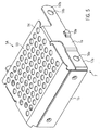
- the conveyor belt 5 includes a conveying surface 13, on which the containers 3 are made, which consists of individual metal sheets 14, which is associated with one of the brackets of the support grid 7.
- the metal sheet 14 contains the attributable thereto portion 13a of the conveying surface 13 and an overlapping web 15 which is substantially perpendicular to the conveying surface 13a and one of the two propeller shafts 8, which are assigned to each of the bracket, overlaps.
- the other propeller shaft 8 of the same bracket is not covered by the associated metal sheet 14, so that the metal sheet adjacent there can overlap with its web 15.
- brackets 7a to 7d and the associated metal sheets 14 each form a segment 5a, from which the conveyor belt 5 is composed, wherein the metal sheets 14 of adjacent segments abut each other closely, so that no gaps open between them, which are not for joint movement around the guide rollers of the endless conveyor belt 5 are necessary.
- the metal sheet 14 is preferably made of stainless steel and is preferably formed perforated, for example in the form of the perforated plate shown.
- the web 15 can be formed from the same perforated plate, simply by bending out, but can also be made separately from an unbroken sheet and fixed to the perforated plate.
- the entire segment 5A with bracket, sheet metal 14 and web 15 is bent from a correspondingly shaped sheet metal blank and welded.
- a support grid 7 for example, in the DE 10 2004 021 262 A1 described supporting grid can be used. Other supporting structures are conceivable.
- the conveyor belt 5 is provided on the lateral, in the conveying direction F extending edges with support and guide bracket 16, which bulge outward and may be resilient or designed for sliding friction.
- the support and guide bracket 16 sit between each two adjacent propeller shafts 8 and are preferably fixed there together with the tensioning device 9.
- the support structure may also have other constructions.
- the support structure may also have other constructions.
- stainless steel other suitable metals can be used.
Landscapes
- Engineering & Computer Science (AREA)
- Mechanical Engineering (AREA)
- Belt Conveyors (AREA)
- Structure Of Belt Conveyors (AREA)
- Rollers For Roller Conveyors For Transfer (AREA)
- Glass Compositions (AREA)
Description
- Die Erfindung bezieht sich auf ein Förderband, insbesondere für einen Pasteur, der im Oberbegriff von Anspruch 1 erläuterten Art.
- Ein derartiges Förderband ist aus der
DE 10 2004 021 262 A1 bekannt. Das bekannte Förderband ist für einen endlosen Umlauf um zwei beabstandete Rollen ausgebildet und dient dazu, mit Füllgut gefüllte Behälter, beispielsweise Flaschen oder Gläser, durch einen Pasteur zu transportieren, wo durch Wärmeeinwirkung über eine bestimmte Zeit eine Pasteurisierung des Inhalts der Behälter erfolgt. Das bekannte Förderband ist aus einzelnen Segmenten aufgebaut, wobei jedes Segment einen oder mehrere Tragbügel aufweist, die miteinander zu einem Traggitter verbunden sind. Durch die Bügel erstrecken sich Stangen, die über die gesamte Breite quer zur Förderrichtung des Förderbandes reichen und sowohl die Segmente einer quer zur Förderrichtung verlaufenden Querreihe miteinander verbinden als auch als Scharnier für eine Relativbewegung der benachbarten Segmente in einer längs zur Förderrichtung laufenden Reihe dienen. Diese Stäbe dienen weiterhin als Lagerung für Abstützrollen, die unter ausgewählten Segmenten angeordnet sind und diese und somit das gesamte Förderband auf einem Träger abstützen. Auf der Oberseite der Bügel ist ein Kunststoffoberteil befestigt, das die Förderfläche bildet. Die Förderfläche wird durch einen geringen Abstand nebeneinander liegenden und hochkant angeordneten Kunststoffstege gebildet, deren Schmalseiten die Förderfläche bilden. Damit sichergestellt ist, dass die Behälter kippsicher auf der Förderfläche ruhen, sind die Abstände zwischen den Kunststoffstegen relativ schmal. Tritt nun innerhalb des Pasteurs ein Glasbruch auf, so können Glasscherben die Förderfläche schartig machen oder sich gar zwischen den Kunststoffstegen verkeilen, so dass das Förderband beschädigt wird. - Die
US 3 220 535 A beschreibt ferner ein endloses Förderband mit plattenförmigen Fördersegmenten. Diese sind beidseitig an seitlichen Gleitblöcken oder Rollen gelagert und von seitlich außerhalb der Gleitblöcke bzw. Rollen angeordneten Ketten angetrieben. Die Fördersegmente des Förderbands sind quer zur Transportrichtung durchgehend ausgebildet. - Die
WO 2007/034 289 A1 beschreibt ferner ein endloses Förderband mit in seitlicher Richtung durchgehenden Bandsegmenten, die über stationär gelagerte Walzen laufen. - Der Erfindung liegt die Aufgabe zugrunde, ein Förderband bereitzustellen, das weniger beschädigungsanfällig ist.
- Die Aufgabe wird durch die im Anspruch 1 beschriebene Kombination der Merkmale gelöst.
- Es hat sich überraschenderweise herausgestellt, dass die beim bekannten Förderband verwendeten Abstützrollen ohne weiteres auch das höhere Gewicht einer metallenen Förderfläche tragen können, ohne dass eine übermäßig erhöhte Antriebsenergie aufgewandt werden muss. Die Kombination der Abstützrollen mit einer Förderfläche aus Metall führt somit zu einem Förderband, das sehr gut mit Glasbruch umgehen kann, ohne dass die bisherigen Nachteile von Stahl- bzw. Metallförderbändern, d.h. ein hoher Bedarf an Antriebsenergie wegen des stark erhöhten Gewichtes, auftritt.
- Vorteilhafte Weiterbildungen der Erfindung sind den Unteransprüchen zu entnehmen.
- Die Verwendung von liegend angeordnetem Metallblech bildet eine sehr glatte Oberfläche, auf der die Behälter auch selbsttätig gut aufgeschoben werden können. Die Verwendung von Lochblech für die Förderfläche schafft ausreichend Abflussmöglichkeit, durch die über- bzw. ausgelaufene Flüssigkeit abgeführt werden kann.
- Die Abstützrollen müssen nicht unbedingt unter jedem Segment vorgesehen sein, wobei bevorzugt die in Querrichtung außenliegenden Segmente durch die Rollen unterstützt werden.
- Die Förderflächen benachbarter Segmente in Querrichtung liegen im Wesentlichen spaltfrei nebeneinander. Dies kann bevorzugt durch eine Querverbindungseinrichtung zwischen quer zur Förderrichtung benachbarten Segmenten erreicht werden. Alternativ oder zusätzlich können an den Enden von Gelenkwellen, die benachbarte Segmente in der Querreihe miteinander verbinden, Spanneinrichtungen vorgesehen sein.
- Bevorzugt sitzen die Abstützrolle auch auf den Gelenkwellen.
- Seitlich vorgesehene Abstütz- und Führungsbügel, die an in Förderrichtung hintereinanderliegenden Gelenkwellen angeordnet sind, sichern einen ruhigen und geraden Lauf des erfindungsgemäßen Förderbandes.
- Ein Ausführungsbeispiel der Erfindung wird nachfolgend anhand der Zeichnungen näher erläutert. Es zeigen:
- Fig. 1
- eine stark schematisierte perspektivische Teildarstellung eines Pasteurs mit erfindungsgemäßem Förderband,
- Fig. 2
- eine perspektivische Draufsicht auf einen Teil des erfindungsgemäßen Förderbandes,
- Fig. 3
- eine Ansicht des erfindungsgemäßen Förderbandes von unten,
- Fig. 4
- eine Ansicht des erfindungsgemäßen Förderbandes in Förderrichtung,
- Fig. 5
- eine vergrößerte Darstellung eines einzelnen Segmentes, und
- Fig. 6
- das herausvergrößerte Detail A aus
Fig. 3 . -
Fig. 1 zeigt in stark schematisierter, perspektivischer Darstellung den Einlaufbereich eines Pasteurs 1, der bis auf das Förderband herkömmlicher Art sein kann. Der Pasteur 1 wird über ein herkömmliches Förderband 2 beliefert, das Behälter 3, dargestellt sind Flaschen, zum Einlaufbereich 1a des Pasteurs 1 bringt. Die Behälter sind bevorzugt Glasbehälter, bei denen die anhand des Standes der Technik beschriebenen Probleme bei Glasbruch auftreten. Die Erfindung ist jedoch für Behälter aller Art einzusetzen und muss auch nicht unbedingt in einem Pasteur verwirklicht werden. - Auf dem Förderband 2 ist die übliche Einlaufschiene 4 vorgesehen, die die auf dem Förderband 2 ankommenden Behälter 3 in den Einlaufbereich 1a leitet. Im Pasteur 1 ist ein Förderband 5 vorgesehen, auf das die Behälter 3 vom Förderband 2 über ein Überschubblech 6 aufgeschoben werden. Das Überschubblech ist glatt, ohne Öffnungen und bevorzugt aus Federstahl. Durch das Förderband 5 werden anschließend die Behälter 3 in Förderrichtung F in den Pasteur hinein, durch ihn hindurch und am gegenüberliegenden Ende, wiederum über ein Überschubblech auf einen Abtransporteur gefördert.
- Das Förderband 5 im Inneren des Pasteurs ist in den
Fig. 2 bis 6 näher erläutert. Das Förderband 5 ist aus einzelnen Segmenten 5A aufgebaut und weist ein Traggitter 7 aus einer Vielzahl miteinander vernetzter Bügel auf, wobei lediglich die Bügel 7a, 7b, 7c, 7d einer quer zur Förderrichtung F verlaufenden Querreihe mit Bezugszeichen gekennzeichnet sind. Die Bügel 7a bis 7d sind innerhalb der Querrichtung miteinander und in Förderrichtung, d.h. innerhalb der Längsreihen, mit benachbarten Bügeln vernetzt. - An den in Förderrichtung F vorderen und hinteren Bereichen 17a, 17b jedes Bügels wird der in Förderrichtung F vor- und nachlaufende Bügel der benachbarten Querreihe überlappt, wobei in den Überlappungsstellen jeweils eine Gelenkwelle 8 in Bohrungen 18a, 18b gelagert ist. Die Gelenkwellen 8 laufen über alle in einer Querreihe befindlichen Segmente 5A. Jeder Bügel kann sich somit um die in Förderrichtung vordere und die in Förderrichtung nachlaufende Gelenkwelle 8 scharnierartig verschwenken. Die Gelenkwellen 8 sind an den seitlichen Rändern über eine Spanneinrichtung 9, beispielsweise einen Spannkeil, verspannt, so dass die auf der gleichen Gelenkwelle 8 sitzenden Bügel 7a bis 7d eng aneinandergepresst werden. Weiterhin sind zwischen den einzelnen Bügeln einer Querreihe die in
Fig. 5 gezeigten Verankerungselemente 10 vorgesehen, die aus einem der Bügel ausgebogenen Blechstreifen 10a bestehen, der in eine im benachbarten Bügel vorgesehene Öffnung 10b eingreift. Durch diese Maßnahmen wird ein im Wesentlichen spalffreier Zusammenhalt der Bügel innerhalb einer Querreihe sichergestellt. - Auf jeder Gelenkwelle 8, jedoch nicht unbedingt in jedem Bügel, ist eine Abstützrolle 11 drehbar gelagert. Im dargestellten Ausführungsbeispiel sind lediglich die beiden äußeren Bügel 7a und 7d jeder Querreihe mit einer Abstützrolle 11 versehen. Die Abstützrollen 11 können jedoch auch regel- oder unregelmäßig, je nach Belastung, über das Traggitter 7 verteilt sein. Die Abstützrollen 11 laufen auf einem Träger 12, der im Innenband vorgesehen ist.
- Das Förderband 5 enthält eine Förderfläche 13, auf der die Behälter 3 stehen, die aus einzelnen Metallblechen 14 besteht, die jeweils einem der Bügel des Traggitters 7 zugeordnet ist. Das Metallblech 14 enthält den auf ihn entfallenden Anteil 13a der Förderfläche 13 und einen Überlappungssteg 15, der im Wesentlichen senkrecht zur Förderfläche 13a verläuft und eine der beiden Gelenkwellen 8, die jedem der Bügel zugeordnet sind, übergreift. Die andere Gelenkwelle 8 des gleichen Bügels wird vom zugeordneten Metallblech 14 nicht überdeckt, so dass das dort benachbarte Metallblech mit seinem Steg 15 übergreifen kann.
- Auf diese Weise bilden Bügel 7a bis 7d und die zugeordneten Metallbleche 14 jeweils ein Segment 5a, aus dem sich das Förderband 5 zusammensetzt, wobei die Metallbleche 14 benachbarter Segmente eng aneinander anstoßen, so dass sich zwischen ihnen keine Spalte auftun, die nicht für eine Gelenkbewegung um die Umlenkwalzen des endlosen Förderbandes 5 notwendig sind.
- Das Metallblech 14 besteht bevorzugt aus Edelstahl und ist bevorzugt durchbrochen ausgebildet, beispielsweise in Form des gezeigten Lochbleches. Der Steg 15 kann aus dem gleichen Lochblech, einfach durch Herausbiegen geformt werden, kann jedoch auch gesondert aus einem undurchbrochenen Blech hergestellt und am Lochblech befestigt werden.
- Im dargestellten Ausführungsbeispiel ist das gesamte Segment 5A mit Bügel, Metallblech 14 und Steg 15 aus einem entsprechend geformten Blechzuschnitt gebogen und verschweißt. Als Traggitter 7 kann jedoch auch beispielsweise das in der
DE 10 2004 021 262 A1 beschriebene Traggitter eingesetzt werden. Andere Tragkonstruktionen sind denkbar. - Das Förderband 5 ist an den seitlichen, in Förderrichtung F verlaufenden Rändern mit Abstütz- und Führungsbügel 16 versehen, die sich nach außen wölben und federnd oder für Gleitreibung ausgebildet sein können. Die Abstütz- und Führungsbügel 16 sitzen zwischen jeweils zwei benachbarten Gelenkwellen 8 und sind dort bevorzugt zusammen mit der Spanneinrichtung 9 befestigt.
- In Abwandlung des beschriebenen und gezeichneten Ausführungsbeispiels kann die Trägerstruktur auch andere Konstruktionen aufweisen. Statt Edelstahl können andere geeignete Metalle verwendet werden.
Claims (11)
- Förderband (5), insbesondere für einen Pasteur (1), mit einer Förderfläche (13) und mit Abstützrollen (11), die unterhalb der Förderfläche (13) angeordnet sind und diese auf einem Träger (12) rollend abstützen, gekennzeichnet durch eine aus Metall gebildete Förderfläche (13), wobei die Förderfläche (13) aus aneinanderstoßenden Segmenten (5A) besteht, die im Wesentlichen spaltfrei nebeneinander liegen.
- Förderband nach Anspruch 1, dadurch gekennzeichnet, dass die Förderfläche (13) aus einem Metallblech (14) besteht, das liegend angeordnet ist.
- Förderband nach Anspruch 1 oder 2, dadurch gekennzeichnet, dass die Förderfläche (13) aus einem Lochblech aus Metall besteht.
- Förderband nach einem der Ansprüche 1 bis 3, dadurch gekennzeichnet, dass die Abstützrollen in vorbestimmter Verteilung unterhalb der Förderfläche (13) angeordnet sind.
- Förderband nach einem der Ansprüche 1 bis 4, dadurch gekennzeichnet, dass sich die Abstützrollen (11) in der Nähe der in Querrichtung äußeren Ränder befinden.
- Förderband nach einem der Ansprüche 1 bis 5, dadurch gekennzeichnet, dass zwischen quer zur Förderrichtung (F) benachbarten Segmenten (5A) eine Querverbindungseinrichtung (10) vorgesehen ist.
- Förderband nach Anspruch einem der Ansprüche 1 bis 6, dadurch gekennzeichnet, dass die Segmente (5A) auf wenigstens einer Gelenkwelle (8) sitzen, die die quer zur Förderrichtung (F) angeordneten Segmente (5A) verbindet, wobei an wenigstens einem Ende der Gelenkwelle (8) eine Spanneinrichtung (9) vorgesehen ist, die die Segmente (5A) gegeneinander presst.
- Förderband nach einem der Ansprüche 1 bis 7, dadurch gekennzeichnet, dass jedes Segment (5A) einen Bereich eines Traggitters (7) und ein einen Teil (13a) der Förderfläche (13) enthaltenes Metallblech (14) aufweist.
- Förderband nach einem der Ansprüche 1 bis 8, dadurch gekennzeichnet, dass jedes Segment (5A) einen Übergriffssteg (15) zum Verzahnen von in Förderrichtung (F) vor- und/oder nachlaufenden Segmente (5A) aufweist.
- Förderband nach einem der Ansprüche 1 bis 9, dadurch gekennzeichnet, dass die Abstützrollen (11) auf Gelenkwellen (8) sitzen, die im Traggitter (7) gelagert sind.
- Förderband nach einem der Ansprüche 1 bis 10, dadurch gekennzeichnet, dass an seitlichen Rändern des Förderbandes (5) Abstütz- und Führungsbügel (16) vorgesehen sind.
Applications Claiming Priority (1)
| Application Number | Priority Date | Filing Date | Title |
|---|---|---|---|
| DE102009040773A DE102009040773A1 (de) | 2009-09-09 | 2009-09-09 | Förderband |
Publications (3)
| Publication Number | Publication Date |
|---|---|
| EP2295348A2 EP2295348A2 (de) | 2011-03-16 |
| EP2295348A3 EP2295348A3 (de) | 2014-01-15 |
| EP2295348B1 true EP2295348B1 (de) | 2016-06-29 |
Family
ID=43332274
Family Applications (1)
| Application Number | Title | Priority Date | Filing Date |
|---|---|---|---|
| EP10173834.2A Active EP2295348B1 (de) | 2009-09-09 | 2010-08-24 | Förderkette |
Country Status (8)
| Country | Link |
|---|---|
| US (1) | US8162134B2 (de) |
| EP (1) | EP2295348B1 (de) |
| CN (1) | CN102020095B (de) |
| BR (1) | BRPI1003500B1 (de) |
| DE (1) | DE102009040773A1 (de) |
| DK (1) | DK2295348T3 (de) |
| ES (1) | ES2584173T3 (de) |
| PL (1) | PL2295348T3 (de) |
Families Citing this family (7)
| Publication number | Priority date | Publication date | Assignee | Title |
|---|---|---|---|---|
| CN105164029B (zh) * | 2013-06-28 | 2016-12-07 | 株式会社椿本链条 | 传送带以及带构成部件 |
| US9663297B1 (en) | 2016-03-15 | 2017-05-30 | Ashworth Bros., Inc. | Linkage assembly for self-supporting conveyor belt |
| CN107826718A (zh) * | 2017-11-23 | 2018-03-23 | 湖北酷我乳业股份有限公司 | 一种含乳饮品消毒生产线 |
| ES2723748B2 (es) | 2018-02-23 | 2020-02-28 | Open Mind Ventures S L U | Estructura reticular flexible |
| DE102019113037B4 (de) | 2019-05-17 | 2024-02-01 | Bernd Münstermann Gmbh & Co. Kg | Plattenförderband aus miteinander gelenkig verbundenen Förderbandsegmenten und Ofen mit einem Plattenförderband |
| DE102020103449A1 (de) * | 2020-02-11 | 2021-08-12 | Bernd Münstermann Gmbh & Co. Kg | Plattenförderband zum Transport einer im Durchlauf mittels eines gasförmigen Temperiermediums thermisch zu behandelnden Materialbahn und Ofen mit wenigstens einem Plattenförderband |
| DE102021100541A1 (de) * | 2021-01-13 | 2022-07-14 | Krones Aktiengesellschaft | Umreifungsvorrichtung und Verfahren zur Herstellung von Umreifungsgebinden |
Family Cites Families (17)
| Publication number | Priority date | Publication date | Assignee | Title |
|---|---|---|---|---|
| US3123202A (en) * | 1964-03-03 | Slatted-type conveyor | ||
| US2987168A (en) * | 1957-10-10 | 1961-06-06 | Ruth R Young | Conveyor mechanism |
| GB868464A (en) * | 1958-07-18 | 1961-05-17 | Supreme Conveyor Belt Company | Improvements relating to endless conveyors |
| US3082861A (en) * | 1959-09-29 | 1963-03-26 | Andrew T Kornylak | Conveyor belt |
| US3220535A (en) * | 1963-07-25 | 1965-11-30 | Proctor & Schwartz Inc | High speed conveyor with wear plates |
| US3550756A (en) * | 1967-09-13 | 1970-12-29 | Kornylac Co | Conveyor having provision for discharging loads at an angle generally transverse to the line of travel on the conveyor |
| GB1286155A (en) * | 1969-09-15 | 1972-08-23 | Efco Ltd | Conveyors |
| DE2100932C3 (de) * | 1971-01-11 | 1973-12-13 | May-Fran Gmbh, 4300 Essen | Scharnierbandforderer fur Metall |
| US3866743A (en) * | 1973-07-20 | 1975-02-18 | Charles T Jorgensen | Hinged metal belt conveyor |
| CN2156157Y (zh) * | 1993-06-30 | 1994-02-16 | 林铭炫 | 简易式输送带 |
| US5651191A (en) * | 1995-07-28 | 1997-07-29 | Wolverine Corporation | Material treatment system |
| DE10033499A1 (de) * | 2000-07-05 | 2002-01-24 | Univ Dresden Tech | Fördergurt aus Elementen sowie Element hierfür |
| US7073651B2 (en) * | 2003-07-30 | 2006-07-11 | Laitram, L.L.C. | Modular mat gravity-advance roller conveyor |
| DE102004021262A1 (de) | 2004-04-30 | 2005-11-17 | Sander Hansen A/S | Pasteur mit Förderband |
| ITMI20051745A1 (it) * | 2005-09-21 | 2007-03-22 | Magaldi Power Spa | Nastro trasportatore a piastre sovrapposte a superficie piana |
| NL1031522C2 (nl) * | 2006-04-05 | 2007-10-08 | Rexnord Flattop Europe Bv | Transportmatmodule, transportmat en transporteur. |
| NL1032089C1 (nl) * | 2006-04-05 | 2007-10-08 | Rexnord Flattop Europe Bv | Transportmatmodule, transportmat en transporteur. |
-
2009
- 2009-09-09 DE DE102009040773A patent/DE102009040773A1/de not_active Ceased
-
2010
- 2010-08-24 EP EP10173834.2A patent/EP2295348B1/de active Active
- 2010-08-24 ES ES10173834.2T patent/ES2584173T3/es active Active
- 2010-08-24 DK DK10173834.2T patent/DK2295348T3/en active
- 2010-08-24 PL PL10173834.2T patent/PL2295348T3/pl unknown
- 2010-09-06 BR BRPI1003500-1A patent/BRPI1003500B1/pt active IP Right Grant
- 2010-09-07 US US12/876,360 patent/US8162134B2/en not_active Expired - Fee Related
- 2010-09-09 CN CN201010280144.9A patent/CN102020095B/zh active Active
Also Published As
| Publication number | Publication date |
|---|---|
| PL2295348T3 (pl) | 2016-12-30 |
| DK2295348T3 (en) | 2016-10-03 |
| BRPI1003500A2 (pt) | 2012-05-29 |
| DE102009040773A1 (de) | 2011-03-10 |
| BRPI1003500B1 (pt) | 2019-05-28 |
| EP2295348A3 (de) | 2014-01-15 |
| ES2584173T3 (es) | 2016-09-26 |
| CN102020095A (zh) | 2011-04-20 |
| EP2295348A2 (de) | 2011-03-16 |
| US20110056810A1 (en) | 2011-03-10 |
| CN102020095B (zh) | 2016-01-20 |
| US8162134B2 (en) | 2012-04-24 |
Similar Documents
| Publication | Publication Date | Title |
|---|---|---|
| EP2295348B1 (de) | Förderkette | |
| EP2030919B1 (de) | Förderanlage zum Transport von Gütern mittels eines Förderbandes | |
| WO2013090969A1 (de) | Kommissionieranlage sowie verfahren zum kommissionieren von artikeln | |
| DE8801643U1 (de) | Bandförderer mit umklappbarem Band | |
| DE4115114A1 (de) | Foerdereinrichtung mit beweglichen trennstegen | |
| DE19616907C5 (de) | Förderbahn für Stückgut, insbesondere für Gepäck-Behälter | |
| EP2563694B1 (de) | Kurvengurtförderer | |
| EP0541850B1 (de) | Kurvengängiges Plattenband | |
| DE69901732T2 (de) | Fördermodul und -matte und System zum Fördern von Produkten | |
| DE19901287C2 (de) | Deckbandförderer | |
| EP2314529B1 (de) | Transporteinheit mit Stauröllchenketten | |
| DE3437049A1 (de) | Foerdereinrichtung | |
| DE102004007590B4 (de) | Dynamischer Puffer | |
| DE60319244T2 (de) | Fördersystem mit einer überschiebvorrichtung zwischen zwei bandförderern und verwendung eines zwischenelementes | |
| EP1744977B1 (de) | Pasteur mit förderband | |
| EP3181528B1 (de) | Förderkette zum transport von glasbehältern durch einen ofen mit als kettenlaschen ausgebildeten stützen sowie fördereinrichtung mit einer solchen förderkette | |
| EP2349876B1 (de) | Förderband für eine streckenförderanlage auf tragseilen oder längsschienen | |
| EP2256070B1 (de) | Bandfördereinrichtung | |
| EP0524458A2 (de) | Kratzerförderer für loses Schüttgut | |
| WO1995029858A1 (de) | Plattenbandförderer | |
| EP2754626B1 (de) | Fördervorrichtung mit konkavem Gurt | |
| DE19506105C1 (de) | Belademaschine für eine Bogentrocknungsanlage | |
| DE69102414T2 (de) | Vorrichtung zum Behandeln von Gegenständen unterschiedlicher Form und Grösse. | |
| DE2558378C3 (de) | Gliederbandförderer mit Traggliedern in Trogform | |
| DE20310185U1 (de) | Rollenbahn |
Legal Events
| Date | Code | Title | Description |
|---|---|---|---|
| PUAI | Public reference made under article 153(3) epc to a published international application that has entered the european phase |
Free format text: ORIGINAL CODE: 0009012 |
|
| AK | Designated contracting states |
Kind code of ref document: A2 Designated state(s): AL AT BE BG CH CY CZ DE DK EE ES FI FR GB GR HR HU IE IS IT LI LT LU LV MC MK MT NL NO PL PT RO SE SI SK SM TR |
|
| AX | Request for extension of the european patent |
Extension state: BA ME RS |
|
| PUAL | Search report despatched |
Free format text: ORIGINAL CODE: 0009013 |
|
| RIC1 | Information provided on ipc code assigned before grant |
Ipc: B65G 17/08 20060101AFI20131119BHEP Ipc: B65G 17/06 20060101ALI20131119BHEP Ipc: B65G 17/24 20060101ALI20131119BHEP |
|
| AK | Designated contracting states |
Kind code of ref document: A3 Designated state(s): AL AT BE BG CH CY CZ DE DK EE ES FI FR GB GR HR HU IE IS IT LI LT LU LV MC MK MT NL NO PL PT RO SE SI SK SM TR |
|
| AX | Request for extension of the european patent |
Extension state: BA ME RS |
|
| RIC1 | Information provided on ipc code assigned before grant |
Ipc: B65G 17/08 20060101AFI20131211BHEP Ipc: B65G 17/24 20060101ALI20131211BHEP Ipc: B65G 17/06 20060101ALI20131211BHEP |
|
| 17P | Request for examination filed |
Effective date: 20140710 |
|
| RBV | Designated contracting states (corrected) |
Designated state(s): AL AT BE BG CH CY CZ DE DK EE ES FI FR GB GR HR HU IE IS IT LI LT LU LV MC MK MT NL NO PL PT RO SE SI SK SM TR |
|
| GRAP | Despatch of communication of intention to grant a patent |
Free format text: ORIGINAL CODE: EPIDOSNIGR1 |
|
| RIC1 | Information provided on ipc code assigned before grant |
Ipc: B65G 17/24 20060101ALI20151218BHEP Ipc: B65G 17/08 20060101AFI20151218BHEP Ipc: B65G 17/40 20060101ALI20151218BHEP Ipc: B65G 17/06 20060101ALI20151218BHEP |
|
| INTG | Intention to grant announced |
Effective date: 20160118 |
|
| GRAS | Grant fee paid |
Free format text: ORIGINAL CODE: EPIDOSNIGR3 |
|
| GRAA | (expected) grant |
Free format text: ORIGINAL CODE: 0009210 |
|
| AK | Designated contracting states |
Kind code of ref document: B1 Designated state(s): AL AT BE BG CH CY CZ DE DK EE ES FI FR GB GR HR HU IE IS IT LI LT LU LV MC MK MT NL NO PL PT RO SE SI SK SM TR |
|
| REG | Reference to a national code |
Ref country code: GB Ref legal event code: FG4D Free format text: NOT ENGLISH |
|
| REG | Reference to a national code |
Ref country code: CH Ref legal event code: EP |
|
| REG | Reference to a national code |
Ref country code: FR Ref legal event code: PLFP Year of fee payment: 7 |
|
| REG | Reference to a national code |
Ref country code: AT Ref legal event code: REF Ref document number: 808915 Country of ref document: AT Kind code of ref document: T Effective date: 20160715 |
|
| REG | Reference to a national code |
Ref country code: IE Ref legal event code: FG4D Free format text: LANGUAGE OF EP DOCUMENT: GERMAN |
|
| REG | Reference to a national code |
Ref country code: DE Ref legal event code: R096 Ref document number: 502010011902 Country of ref document: DE |
|
| REG | Reference to a national code |
Ref country code: NL Ref legal event code: FP |
|
| REG | Reference to a national code |
Ref country code: ES Ref legal event code: FG2A Ref document number: 2584173 Country of ref document: ES Kind code of ref document: T3 Effective date: 20160926 |
|
| REG | Reference to a national code |
Ref country code: DK Ref legal event code: T3 Effective date: 20160926 |
|
| REG | Reference to a national code |
Ref country code: LT Ref legal event code: MG4D |
|
| PG25 | Lapsed in a contracting state [announced via postgrant information from national office to epo] |
Ref country code: NO Free format text: LAPSE BECAUSE OF FAILURE TO SUBMIT A TRANSLATION OF THE DESCRIPTION OR TO PAY THE FEE WITHIN THE PRESCRIBED TIME-LIMIT Effective date: 20160929 Ref country code: FI Free format text: LAPSE BECAUSE OF FAILURE TO SUBMIT A TRANSLATION OF THE DESCRIPTION OR TO PAY THE FEE WITHIN THE PRESCRIBED TIME-LIMIT Effective date: 20160629 Ref country code: LT Free format text: LAPSE BECAUSE OF FAILURE TO SUBMIT A TRANSLATION OF THE DESCRIPTION OR TO PAY THE FEE WITHIN THE PRESCRIBED TIME-LIMIT Effective date: 20160629 |
|
| PG25 | Lapsed in a contracting state [announced via postgrant information from national office to epo] |
Ref country code: GR Free format text: LAPSE BECAUSE OF FAILURE TO SUBMIT A TRANSLATION OF THE DESCRIPTION OR TO PAY THE FEE WITHIN THE PRESCRIBED TIME-LIMIT Effective date: 20160930 Ref country code: LV Free format text: LAPSE BECAUSE OF FAILURE TO SUBMIT A TRANSLATION OF THE DESCRIPTION OR TO PAY THE FEE WITHIN THE PRESCRIBED TIME-LIMIT Effective date: 20160629 Ref country code: SE Free format text: LAPSE BECAUSE OF FAILURE TO SUBMIT A TRANSLATION OF THE DESCRIPTION OR TO PAY THE FEE WITHIN THE PRESCRIBED TIME-LIMIT Effective date: 20160629 Ref country code: HR Free format text: LAPSE BECAUSE OF FAILURE TO SUBMIT A TRANSLATION OF THE DESCRIPTION OR TO PAY THE FEE WITHIN THE PRESCRIBED TIME-LIMIT Effective date: 20160629 |
|
| PG25 | Lapsed in a contracting state [announced via postgrant information from national office to epo] |
Ref country code: BE Free format text: LAPSE BECAUSE OF NON-PAYMENT OF DUE FEES Effective date: 20160831 |
|
| PG25 | Lapsed in a contracting state [announced via postgrant information from national office to epo] |
Ref country code: SK Free format text: LAPSE BECAUSE OF FAILURE TO SUBMIT A TRANSLATION OF THE DESCRIPTION OR TO PAY THE FEE WITHIN THE PRESCRIBED TIME-LIMIT Effective date: 20160629 Ref country code: RO Free format text: LAPSE BECAUSE OF FAILURE TO SUBMIT A TRANSLATION OF THE DESCRIPTION OR TO PAY THE FEE WITHIN THE PRESCRIBED TIME-LIMIT Effective date: 20160629 Ref country code: EE Free format text: LAPSE BECAUSE OF FAILURE TO SUBMIT A TRANSLATION OF THE DESCRIPTION OR TO PAY THE FEE WITHIN THE PRESCRIBED TIME-LIMIT Effective date: 20160629 Ref country code: IS Free format text: LAPSE BECAUSE OF FAILURE TO SUBMIT A TRANSLATION OF THE DESCRIPTION OR TO PAY THE FEE WITHIN THE PRESCRIBED TIME-LIMIT Effective date: 20161029 |
|
| PG25 | Lapsed in a contracting state [announced via postgrant information from national office to epo] |
Ref country code: SM Free format text: LAPSE BECAUSE OF FAILURE TO SUBMIT A TRANSLATION OF THE DESCRIPTION OR TO PAY THE FEE WITHIN THE PRESCRIBED TIME-LIMIT Effective date: 20160629 Ref country code: PT Free format text: LAPSE BECAUSE OF FAILURE TO SUBMIT A TRANSLATION OF THE DESCRIPTION OR TO PAY THE FEE WITHIN THE PRESCRIBED TIME-LIMIT Effective date: 20161031 |
|
| REG | Reference to a national code |
Ref country code: DE Ref legal event code: R097 Ref document number: 502010011902 Country of ref document: DE |
|
| PG25 | Lapsed in a contracting state [announced via postgrant information from national office to epo] |
Ref country code: MC Free format text: LAPSE BECAUSE OF FAILURE TO SUBMIT A TRANSLATION OF THE DESCRIPTION OR TO PAY THE FEE WITHIN THE PRESCRIBED TIME-LIMIT Effective date: 20160629 |
|
| REG | Reference to a national code |
Ref country code: CH Ref legal event code: PL |
|
| PG25 | Lapsed in a contracting state [announced via postgrant information from national office to epo] |
Ref country code: LI Free format text: LAPSE BECAUSE OF NON-PAYMENT OF DUE FEES Effective date: 20160831 Ref country code: CH Free format text: LAPSE BECAUSE OF NON-PAYMENT OF DUE FEES Effective date: 20160831 |
|
| PLBE | No opposition filed within time limit |
Free format text: ORIGINAL CODE: 0009261 |
|
| STAA | Information on the status of an ep patent application or granted ep patent |
Free format text: STATUS: NO OPPOSITION FILED WITHIN TIME LIMIT |
|
| REG | Reference to a national code |
Ref country code: IE Ref legal event code: MM4A |
|
| 26N | No opposition filed |
Effective date: 20170330 |
|
| REG | Reference to a national code |
Ref country code: FR Ref legal event code: PLFP Year of fee payment: 8 |
|
| PG25 | Lapsed in a contracting state [announced via postgrant information from national office to epo] |
Ref country code: IE Free format text: LAPSE BECAUSE OF NON-PAYMENT OF DUE FEES Effective date: 20160824 |
|
| PG25 | Lapsed in a contracting state [announced via postgrant information from national office to epo] |
Ref country code: SI Free format text: LAPSE BECAUSE OF FAILURE TO SUBMIT A TRANSLATION OF THE DESCRIPTION OR TO PAY THE FEE WITHIN THE PRESCRIBED TIME-LIMIT Effective date: 20160629 Ref country code: LU Free format text: LAPSE BECAUSE OF NON-PAYMENT OF DUE FEES Effective date: 20160824 Ref country code: BG Free format text: LAPSE BECAUSE OF FAILURE TO SUBMIT A TRANSLATION OF THE DESCRIPTION OR TO PAY THE FEE WITHIN THE PRESCRIBED TIME-LIMIT Effective date: 20160929 |
|
| PG25 | Lapsed in a contracting state [announced via postgrant information from national office to epo] |
Ref country code: CY Free format text: LAPSE BECAUSE OF FAILURE TO SUBMIT A TRANSLATION OF THE DESCRIPTION OR TO PAY THE FEE WITHIN THE PRESCRIBED TIME-LIMIT Effective date: 20160629 Ref country code: HU Free format text: LAPSE BECAUSE OF FAILURE TO SUBMIT A TRANSLATION OF THE DESCRIPTION OR TO PAY THE FEE WITHIN THE PRESCRIBED TIME-LIMIT; INVALID AB INITIO Effective date: 20100824 |
|
| PG25 | Lapsed in a contracting state [announced via postgrant information from national office to epo] |
Ref country code: MT Free format text: LAPSE BECAUSE OF FAILURE TO SUBMIT A TRANSLATION OF THE DESCRIPTION OR TO PAY THE FEE WITHIN THE PRESCRIBED TIME-LIMIT Effective date: 20160629 Ref country code: TR Free format text: LAPSE BECAUSE OF FAILURE TO SUBMIT A TRANSLATION OF THE DESCRIPTION OR TO PAY THE FEE WITHIN THE PRESCRIBED TIME-LIMIT Effective date: 20160629 Ref country code: MK Free format text: LAPSE BECAUSE OF FAILURE TO SUBMIT A TRANSLATION OF THE DESCRIPTION OR TO PAY THE FEE WITHIN THE PRESCRIBED TIME-LIMIT Effective date: 20160629 |
|
| REG | Reference to a national code |
Ref country code: FR Ref legal event code: PLFP Year of fee payment: 9 |
|
| PG25 | Lapsed in a contracting state [announced via postgrant information from national office to epo] |
Ref country code: AL Free format text: LAPSE BECAUSE OF FAILURE TO SUBMIT A TRANSLATION OF THE DESCRIPTION OR TO PAY THE FEE WITHIN THE PRESCRIBED TIME-LIMIT Effective date: 20160629 |
|
| PGFP | Annual fee paid to national office [announced via postgrant information from national office to epo] |
Ref country code: GB Payment date: 20210714 Year of fee payment: 12 Ref country code: DK Payment date: 20210810 Year of fee payment: 12 Ref country code: ES Payment date: 20210903 Year of fee payment: 12 |
|
| REG | Reference to a national code |
Ref country code: DK Ref legal event code: EBP Effective date: 20220831 |
|
| GBPC | Gb: european patent ceased through non-payment of renewal fee |
Effective date: 20220824 |
|
| P01 | Opt-out of the competence of the unified patent court (upc) registered |
Effective date: 20230523 |
|
| PG25 | Lapsed in a contracting state [announced via postgrant information from national office to epo] |
Ref country code: DK Free format text: LAPSE BECAUSE OF NON-PAYMENT OF DUE FEES Effective date: 20220831 |
|
| REG | Reference to a national code |
Ref country code: ES Ref legal event code: FD2A Effective date: 20230929 |
|
| PG25 | Lapsed in a contracting state [announced via postgrant information from national office to epo] |
Ref country code: GB Free format text: LAPSE BECAUSE OF NON-PAYMENT OF DUE FEES Effective date: 20220824 Ref country code: ES Free format text: LAPSE BECAUSE OF NON-PAYMENT OF DUE FEES Effective date: 20220825 |
|
| PGFP | Annual fee paid to national office [announced via postgrant information from national office to epo] |
Ref country code: CZ Payment date: 20230728 Year of fee payment: 14 |
|
| PGFP | Annual fee paid to national office [announced via postgrant information from national office to epo] |
Ref country code: PL Payment date: 20230713 Year of fee payment: 14 |
|
| PGFP | Annual fee paid to national office [announced via postgrant information from national office to epo] |
Ref country code: AT Payment date: 20240725 Year of fee payment: 15 |
|
| PG25 | Lapsed in a contracting state [announced via postgrant information from national office to epo] |
Ref country code: CZ Free format text: LAPSE BECAUSE OF NON-PAYMENT OF DUE FEES Effective date: 20240824 |
|
| PGFP | Annual fee paid to national office [announced via postgrant information from national office to epo] |
Ref country code: NL Payment date: 20250704 Year of fee payment: 16 |
|
| PGFP | Annual fee paid to national office [announced via postgrant information from national office to epo] |
Ref country code: DE Payment date: 20250702 Year of fee payment: 16 |
|
| PGFP | Annual fee paid to national office [announced via postgrant information from national office to epo] |
Ref country code: IT Payment date: 20250722 Year of fee payment: 16 |
|
| PGFP | Annual fee paid to national office [announced via postgrant information from national office to epo] |
Ref country code: FR Payment date: 20250703 Year of fee payment: 16 |